EP1599280B1 - Rührvorrichtung und verfahren zur verwendung einer dergestalten vorrichtung - Google Patents
Rührvorrichtung und verfahren zur verwendung einer dergestalten vorrichtung Download PDFInfo
- Publication number
- EP1599280B1 EP1599280B1 EP04715369A EP04715369A EP1599280B1 EP 1599280 B1 EP1599280 B1 EP 1599280B1 EP 04715369 A EP04715369 A EP 04715369A EP 04715369 A EP04715369 A EP 04715369A EP 1599280 B1 EP1599280 B1 EP 1599280B1
- Authority
- EP
- European Patent Office
- Prior art keywords
- conduit
- stirrer
- vessel
- section
- materials
- Prior art date
- Legal status (The legal status is an assumption and is not a legal conclusion. Google has not performed a legal analysis and makes no representation as to the accuracy of the status listed.)
- Expired - Lifetime
Links
- 238000003756 stirring Methods 0.000 title claims description 21
- 238000000034 method Methods 0.000 title claims description 18
- 239000000463 material Substances 0.000 claims abstract description 72
- 238000006243 chemical reaction Methods 0.000 claims description 16
- 239000003054 catalyst Substances 0.000 description 24
- 238000012360 testing method Methods 0.000 description 13
- 229920000642 polymer Polymers 0.000 description 11
- 230000008878 coupling Effects 0.000 description 9
- 238000010168 coupling process Methods 0.000 description 9
- 238000005859 coupling reaction Methods 0.000 description 9
- 239000007787 solid Substances 0.000 description 9
- 238000002474 experimental method Methods 0.000 description 6
- 238000002156 mixing Methods 0.000 description 6
- 239000000047 product Substances 0.000 description 6
- 239000002245 particle Substances 0.000 description 5
- 239000002002 slurry Substances 0.000 description 5
- IJGRMHOSHXDMSA-UHFFFAOYSA-N Atomic nitrogen Chemical compound N#N IJGRMHOSHXDMSA-UHFFFAOYSA-N 0.000 description 4
- IMNFDUFMRHMDMM-UHFFFAOYSA-N N-Heptane Chemical compound CCCCCCC IMNFDUFMRHMDMM-UHFFFAOYSA-N 0.000 description 4
- FAPWRFPIFSIZLT-UHFFFAOYSA-M Sodium chloride Chemical compound [Na+].[Cl-] FAPWRFPIFSIZLT-UHFFFAOYSA-M 0.000 description 4
- 230000000903 blocking effect Effects 0.000 description 4
- QQONPFPTGQHPMA-UHFFFAOYSA-N propylene Natural products CC=C QQONPFPTGQHPMA-UHFFFAOYSA-N 0.000 description 4
- 125000004805 propylene group Chemical group [H]C([H])([H])C([H])([*:1])C([H])([H])[*:2] 0.000 description 4
- 239000004743 Polypropylene Substances 0.000 description 3
- 230000008901 benefit Effects 0.000 description 3
- -1 polypropylene Polymers 0.000 description 3
- 229920001155 polypropylene Polymers 0.000 description 3
- 230000008569 process Effects 0.000 description 3
- VGGSQFUCUMXWEO-UHFFFAOYSA-N Ethene Chemical compound C=C VGGSQFUCUMXWEO-UHFFFAOYSA-N 0.000 description 2
- 239000005977 Ethylene Substances 0.000 description 2
- 230000009471 action Effects 0.000 description 2
- 238000001311 chemical methods and process Methods 0.000 description 2
- 239000007795 chemical reaction product Substances 0.000 description 2
- 230000003247 decreasing effect Effects 0.000 description 2
- 230000000694 effects Effects 0.000 description 2
- 238000005243 fluidization Methods 0.000 description 2
- 239000007789 gas Substances 0.000 description 2
- 238000000227 grinding Methods 0.000 description 2
- 238000002347 injection Methods 0.000 description 2
- 239000007924 injection Substances 0.000 description 2
- 239000007788 liquid Substances 0.000 description 2
- 229910052757 nitrogen Inorganic materials 0.000 description 2
- 238000006116 polymerization reaction Methods 0.000 description 2
- 238000002360 preparation method Methods 0.000 description 2
- 239000011780 sodium chloride Substances 0.000 description 2
- 238000013019 agitation Methods 0.000 description 1
- 238000006555 catalytic reaction Methods 0.000 description 1
- 230000000052 comparative effect Effects 0.000 description 1
- 239000000203 mixture Substances 0.000 description 1
- 239000000178 monomer Substances 0.000 description 1
- 239000013618 particulate matter Substances 0.000 description 1
- 239000000376 reactant Substances 0.000 description 1
- 230000035484 reaction time Effects 0.000 description 1
- 230000009467 reduction Effects 0.000 description 1
- 230000000717 retained effect Effects 0.000 description 1
- 238000007789 sealing Methods 0.000 description 1
- 239000011949 solid catalyst Substances 0.000 description 1
- 239000011343 solid material Substances 0.000 description 1
- 239000012265 solid product Substances 0.000 description 1
- 239000000725 suspension Substances 0.000 description 1
- 238000011179 visual inspection Methods 0.000 description 1
- 238000005406 washing Methods 0.000 description 1
Images
Classifications
-
- B—PERFORMING OPERATIONS; TRANSPORTING
- B01—PHYSICAL OR CHEMICAL PROCESSES OR APPARATUS IN GENERAL
- B01J—CHEMICAL OR PHYSICAL PROCESSES, e.g. CATALYSIS OR COLLOID CHEMISTRY; THEIR RELEVANT APPARATUS
- B01J8/00—Chemical or physical processes in general, conducted in the presence of fluids and solid particles; Apparatus for such processes
- B01J8/18—Chemical or physical processes in general, conducted in the presence of fluids and solid particles; Apparatus for such processes with fluidised particles
- B01J8/24—Chemical or physical processes in general, conducted in the presence of fluids and solid particles; Apparatus for such processes with fluidised particles according to "fluidised-bed" technique
- B01J8/38—Chemical or physical processes in general, conducted in the presence of fluids and solid particles; Apparatus for such processes with fluidised particles according to "fluidised-bed" technique with fluidised bed containing a rotatable device or being subject to rotation or to a circulatory movement, i.e. leaving a vessel and subsequently re-entering it
- B01J8/382—Chemical or physical processes in general, conducted in the presence of fluids and solid particles; Apparatus for such processes with fluidised particles according to "fluidised-bed" technique with fluidised bed containing a rotatable device or being subject to rotation or to a circulatory movement, i.e. leaving a vessel and subsequently re-entering it with a rotatable device only
-
- B—PERFORMING OPERATIONS; TRANSPORTING
- B01—PHYSICAL OR CHEMICAL PROCESSES OR APPARATUS IN GENERAL
- B01F—MIXING, e.g. DISSOLVING, EMULSIFYING OR DISPERSING
- B01F27/00—Mixers with rotary stirring devices in fixed receptacles; Kneaders
- B01F27/05—Stirrers
- B01F27/11—Stirrers characterised by the configuration of the stirrers
- B01F27/19—Stirrers with two or more mixing elements mounted in sequence on the same axis
- B01F27/192—Stirrers with two or more mixing elements mounted in sequence on the same axis with dissimilar elements
- B01F27/1921—Stirrers with two or more mixing elements mounted in sequence on the same axis with dissimilar elements comprising helical elements and paddles
-
- B—PERFORMING OPERATIONS; TRANSPORTING
- B01—PHYSICAL OR CHEMICAL PROCESSES OR APPARATUS IN GENERAL
- B01F—MIXING, e.g. DISSOLVING, EMULSIFYING OR DISPERSING
- B01F35/00—Accessories for mixers; Auxiliary operations or auxiliary devices; Parts or details of general application
- B01F35/75—Discharge mechanisms
- B01F35/752—Discharge mechanisms with arrangements for converting the mechanism from mixing to discharging, e.g. by either guiding a mixture back into a receptacle or discharging it
-
- B—PERFORMING OPERATIONS; TRANSPORTING
- B01—PHYSICAL OR CHEMICAL PROCESSES OR APPARATUS IN GENERAL
- B01J—CHEMICAL OR PHYSICAL PROCESSES, e.g. CATALYSIS OR COLLOID CHEMISTRY; THEIR RELEVANT APPARATUS
- B01J19/00—Chemical, physical or physico-chemical processes in general; Their relevant apparatus
- B01J19/0053—Details of the reactor
- B01J19/0066—Stirrers
-
- B—PERFORMING OPERATIONS; TRANSPORTING
- B01—PHYSICAL OR CHEMICAL PROCESSES OR APPARATUS IN GENERAL
- B01J—CHEMICAL OR PHYSICAL PROCESSES, e.g. CATALYSIS OR COLLOID CHEMISTRY; THEIR RELEVANT APPARATUS
- B01J19/00—Chemical, physical or physico-chemical processes in general; Their relevant apparatus
- B01J19/18—Stationary reactors having moving elements inside
-
- B—PERFORMING OPERATIONS; TRANSPORTING
- B01—PHYSICAL OR CHEMICAL PROCESSES OR APPARATUS IN GENERAL
- B01F—MIXING, e.g. DISSOLVING, EMULSIFYING OR DISPERSING
- B01F2215/00—Auxiliary or complementary information in relation with mixing
- B01F2215/04—Technical information in relation with mixing
- B01F2215/0413—Numerical information
- B01F2215/0418—Geometrical information
- B01F2215/0427—Numerical distance values, e.g. separation, position
-
- B—PERFORMING OPERATIONS; TRANSPORTING
- B01—PHYSICAL OR CHEMICAL PROCESSES OR APPARATUS IN GENERAL
- B01F—MIXING, e.g. DISSOLVING, EMULSIFYING OR DISPERSING
- B01F2215/00—Auxiliary or complementary information in relation with mixing
- B01F2215/04—Technical information in relation with mixing
- B01F2215/0413—Numerical information
- B01F2215/0418—Geometrical information
- B01F2215/0431—Numerical size values, e.g. diameter of a hole or conduit, area, volume, length, width, or ratios thereof
-
- B—PERFORMING OPERATIONS; TRANSPORTING
- B01—PHYSICAL OR CHEMICAL PROCESSES OR APPARATUS IN GENERAL
- B01J—CHEMICAL OR PHYSICAL PROCESSES, e.g. CATALYSIS OR COLLOID CHEMISTRY; THEIR RELEVANT APPARATUS
- B01J2208/00—Processes carried out in the presence of solid particles; Reactors therefor
- B01J2208/00796—Details of the reactor or of the particulate material
- B01J2208/00823—Mixing elements
- B01J2208/00858—Moving elements
- B01J2208/00867—Moving elements inside the bed, e.g. rotary mixer
-
- B—PERFORMING OPERATIONS; TRANSPORTING
- B01—PHYSICAL OR CHEMICAL PROCESSES OR APPARATUS IN GENERAL
- B01J—CHEMICAL OR PHYSICAL PROCESSES, e.g. CATALYSIS OR COLLOID CHEMISTRY; THEIR RELEVANT APPARATUS
- B01J2219/00—Chemical, physical or physico-chemical processes in general; Their relevant apparatus
- B01J2219/00761—Details of the reactor
- B01J2219/00763—Baffles
- B01J2219/00779—Baffles attached to the stirring means
Definitions
- This invention relates to a stirring apparatus and its method of use.
- Processes are known in which materials are stirred within a vessel.
- numerous chemical processes such as chemical reactions, involve stirring of reactants together to produce products, which are discharged from the vessel (reactor).
- discharge of material from the vessel may be achieved by allowing the material to flow through a suitable conduit.
- the conduit is preferably located at the lowest point (base) of the vessel.
- the conduit will normally comprise a valve or other sealing means.
- the valve it is often not possible or desirable for the valve to be located on the conduit at a position close to the vessel.
- the vessel may be heated, for example, by being located in a suitable heated enclosure, such as an oven or a furnace. It may be desirable to have the valve outside that heated area so that it can be readily accessed by an operator and/or so that the valve does not itself get too hot.
- valve is located at a distance away from the vessel there is thus a significant length of conduit between the valve and the vessel. Material in the vessel may settle out from the vessel into said conduit.
- conduit the longer the conduit, the more likely the conduit is to become blocked, which can cause problems with discharge of materials from the apparatus. This is particularly true where solids or slurries are present in a vessel, for example as reaction products, since such products are often difficult to remove from a vessel.
- stirring apparatus which overcomes or at least mitigates these problems.
- US 4,690,804 relates to catalytic reactions.
- US 4,690,804 relates to a mixing tank for catalyst to be introduced into a reactor.
- the mixing tank has a cylindrical outlet conduit at the base of the tank, and an agitator on a shaft within the tank which terminates in a spiral configuration located within the outlet conduit.
- the agitator of US 4,690,804 provides agitation within the conduit, preventing bridging of the outlet conduit as catalyst is passed through the conduit from the mixing tank and into a receiver (reaction) vessel below.
- the agitator of US 4,690,804 is adapted to convey material within the conduit out of the mixing tank.
- FR-A- 2 083 160 discloses a reactor having a conduct at its bottom, and a stirrer, a section of which being located in the reactor and a section of which being located in the conduit.
- the present invention provides a vessel having a conduit extending therefrom, which has an improved stirrer therein, said stirrer being adapted to convey material within the conduit in a direction towards-the vessel and/or in a direction away from the vessel.
- the present invention provides an apparatus comprising a vessel having a conduit extending therefrom, and a stirrer, a section of which is adapted to be located within the conduit and a section of which is adapted to be located within the vessel, wherein said stirrer is adapted such that, in use, material contained within the conduit is conveyed in a direction towards the vessel.
- material within the conduit is conveyed in to the vessel by the action of the stirrer.
- material being stirred in the vessel is thus prevented from settling in the conduit and is conveyed back into the vessel.
- the present invention provides an apparatus comprising a vessel having a conduit extending therefrom, and a stirrer, a section of which is adapted to be located within the conduit and a section of which is adapted to be located within the vessel, wherein said stirrer is adapted such that, in use, material contained within the conduit is conveyed through the conduit in a direction away from the vessel.
- material within the conduit is conveyed in a direction away from the vessel by the action of the stirrer.
- material may be conveyed out of the apparatus, facilitating discharge of said material.
- the apparatus is such that material in the conduit may be conveyed, alternatively, in a direction towards the vessel or in a direction away from the vessel by the same stirrer.
- the present invention provides an apparatus, comprising a vessel having a conduit extending therefrom, and a stirrer, a section of which is adapted to be located within the conduit and a section of which is adapted to be located within the vessel, wherein said stirrer is adapted such that, when rotated in a first direction, material contained within the conduit is conveyed in a direction towards the vessel, and when rotated in a second direction, material contained within the conduit is conveyed through the conduit in a direction away from the vessel.
- conduit extends from the lowest point (base) of the vessel. This configuration allows the vessel to be completely emptied of material most readily.
- the apparatus may also comprise a suitable stirrer drive.
- the suitable stirrer drive is any that is able to rotate the stirrer in the required direction.
- the stirrer drive must be able to rotate the stirrer in both the first direction and the second, opposite, direction i.e. any suitable bi-directional stirrer drive.
- the stirrer may be connected to the stirrer drive by a suitable first coupling.
- the first coupling may be any suitable coupling that allows the stirrer to be connected to (and rotated by) the drive, preferably a coupling that allows the stirrer to be connected and disconnected from the drive.
- the stirrer preferably ends in a suitable tip, for example, with a flat, round or pointed end.
- the stirrer drive is located above the conduit and the stirrer is adapted to extend from said stirrer drive through the vessel and into the conduit.
- the tip of the stirrer is preferably located on the section of the stirrer adapted to be located within the conduit.
- the stirrer may be defined by a first part adapted to be connected to a suitable stirrer drive, and comprising the section of the stirrer which is adapted to be located within the vessel, and a second part, adapted to be connected to said first part and comprising the section of the stirrer which is adapted to be located within the conduit, wherein said second part is adapted such that, in use, material contained within the conduit may be conveyed in a direction towards or in a direction away from the vessel as described herein.
- first part and the second part are connected together to form the stirrer.
- the connection of the first and second parts may be a fixed, permanent connection.
- the stirrer could be formed as a single piece comprising said first and second parts or the stirrer could be formed of first and second parts which have been formed separately and then welded together.
- the second part and the first part may be connected by a suitable second coupling that allows the parts to rotate together when connected, and also allows the second part to be disconnected from the first part.
- the section of the stirrer which is adapted to be located within the vessel is adapted to stir materials in the vessel when the stirrer is rotated.
- the section of the stirrer which is adapted to be located within the vessel may comprise a shaft having one or more stirrer blades.
- the shaft may have any suitable elongated shape or structure, for example, of cylindrical, square, hexagonal or similar cross-section, preferably cylindrical.
- the shaft may have a constant cross-section, for example, cylindrical and of constant diameter, or the shaft may have varying cross-section along its length, for example, varying diameter.
- the one or more stirrer blades may comprise, for example, one or more paddle-type stirrers with two or more, for example 2 to 6 blades each, or one or more helical projections from the shaft. Where there are more than one such stirrers or projections, for example, they may be located at different positions on the shaft.
- the section of the stirrer which is adapted to be located within the conduit refers to the section of the stirrer that is located within the conduit when part of the apparatus according to the present invention.
- the section of the stirrer which is adapted to be located within the conduit comprises one or more flutes which describe a helical path about the rotational axis of the stirrer.
- the section of the stirrer which is adapted to be located within the conduit may comprise an elongate core, having one or more flutes.
- the core may be of cylindrical, square, hexagonal or similar cross-section, preferably cylindrical.
- the core may be of constant cross-section, or the core may have varying cross-section along its length, for example, varying diameter.
- the section of the stirrer which is adapted to be located within the conduit may comprise a threaded structure similar to that seen on a screw or bolt.
- the section of the stirrer which is adapted to be located within the conduit may comprise a structure similar to a drill-bit or screw extruder.
- the section of the stirrer which is adapted to be located within the conduit preferably comprises one or more flutes which describe a helical path about the rotational axis of the stirrer. Where one or more flutes describe a helical path about the rotational axis of the stirrer this defines a "fluted section" of the stirrer.
- the fluted section may form only a part of the section which is adapted to be located within the conduit, but, preferably, the whole of the section which is adapted to be located within the conduit is fluted.
- the fluted section is not limited to the section which is adapted to be located within the conduit, and may, for example, extend from this section over sections of the stirrer not adapted to be located within the conduit.
- the fluted section may be defined by one or more of the following parameters:
- the one or more flutes may be one or more right-hand flutes, or, alternatively, one or more left-hand flutes.
- a right-hand flute means that the path of the flute, when viewed from the tip, is directed back from the tip in a clockwise direction. Conversely, the path of a left-hand flute, when viewed from the tip, is directed back from the tip in an anti-clockwise direction.
- a right-hand flute will move material along the flutes away from the tip when rotated in an anti-clockwise direction as viewed from the tip.
- the number of flutes around the core is one to four, more preferably one or two, and most preferably two. In general, for a fixed diameter fluted section, the larger the number of flutes then the smaller the width of each (see point (v) below).
- the one or more flutes will be separated by one or more lands (the solid parts between adjacent flutes). For example, there will be one land between adjacent turns of one flute, or two or more lands between two or more flutes.
- the helical angle of a flute is the angle between the tangent to the flute, and a plane containing the axis of the fluted section.
- the flutes may be at any suitable helical angle.
- the helical angle is between 20 and 70°, preferably between 30 and 60°, and more preferably between 40 and 50°.
- the number of turns that the flute makes will depend on the helical angle of the flute and the length of the fluted section.
- the flutes may make one complete turn or may make more than one complete turn around the rotational axis.
- the width of a flute or land refers to the distance across the flute or land measured at a right angle to its edge. Wider and deeper flutes may be preferred for materials that comprise relatively large particles. Alternatively, smaller flutes may be preferred if they allow increased control of discharge of material from the vessel when the stirrer is rotated in the second direction. Most preferably, the flutes and lands are of similar width.
- the flutes may be of any suitable cross-sectional shape, such as semi-circular.
- the effective diameter of the fluted section is the diameter of the circle of maximum size described by the fluted section when the fluted section is rotated about its linear central axis. This is described further below.
- the tip of the stirrer is located on the section of the stirrer adapted to be located within the conduit. Most preferably, the tip forms part of the fluted section.
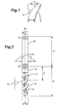
- the fluted section may therefore be further defined by the tip (or point) angle, which is the angle formed at the tip, as shown in Figure 1.
- the tip angle is not critical to the present invention, but is typically between 60° and 180°.
- the second part of the stirrer preferably comprises the fluted section for at least the section adapted to be located within the conduit. More preferably the fluted section forms at least 80% of the length of the second part, and most preferably at least 90% of its length. The remainder of the second part, if any, preferably comprises one or more non-fluted sections, such as a shank or couplings.
- the second part comprises a single fluted section, which fluted section commences at the tip of the stirrer and forms at least 90% of the length of the second part.
- the non-fluted section, if any, of the second part preferably comprises a shank part and may, optionally, also comprise a coupling for connection to the shaft of the first part.
- the section of the stirrer which is adapted to be located within the conduit will have an effective diameter, D(1), at a particular distance (1) along the section.
- the effective diameter of the section, at a particular distance along the section is the diameter of the circle of maximum size described by the section at the distance, 1, when the stirrer is rotated about its linear central axis.
- this section may be of constant effective diameter along its length (i.e. D(1) is constant), or the effective diameter may vary along its length.
- the section of the stirrer which is adapted to be located within the conduit may be stepped or tapered along it length such that the effective diameter may get smaller moving along the length of the section.
- the section of the stirrer which is adapted to be located within the conduit must have an effective diameter smaller than the minimum inner cross-section in the respective part of the conduit.
- “respective part” of the conduit is meant the part of the conduit in which a particular part of the stirrer is located when in use.
- the conduit is preferably cylindrical, and hence, in this case, the section of the stirrer which is adapted to be located within the conduit must have an effective diameter smaller than the diameter of the respective part of the conduit.
- the cylindrical conduit may be of constant inner diameter along its length or the inner diameter may vary along its length.
- the inner diameter of the conduit may be stepped or may taper such that the inner diameter reduces with length away from the vessel.
- the cylindrical conduit is of constant inner diameter along its length.
- the effective diameter of the section of the stirrer which is adapted to be located within the conduit is preferably also of constant diameter.
- the effective diameter of the section of the stirrer which is adapted to be located within the conduit may vary correspondingly, for example, the section of the stirrer which is adapted to be located within the conduit may be tapered to fit within a tapered conduit.
- the section of the stirrer which is adapted to be located within the conduit is such that, in use within the conduit, the effective diameter of the portion at a location within the conduit is at least 50% of the inner diameter of the conduit at that location within the conduit, more preferably at least 60% and most preferably in the range 70-90%.
- the apparatus according to the present invention may be of any suitable size.
- the apparatus according to the present invention will now be described with reference to a preferred size, the apparatus according to the present invention may readily be sized for use with both larger and smaller vessels.
- the apparatus comprises a relatively small vessel, such as relatively small reaction vessels.
- a relatively small vessel such as relatively small reaction vessels.
- suitable small reaction vessels include batch reactors, typically of volume from 1 ml to 5 litres, preferably of at least 10 ml in volume and/or up to 500 ml in volume.
- the conduit is an outlet conduit, for example, for removal of material, such as reaction product, from the vessel.
- the effective diameter at a particular length, D(1), of the section of the stirrer which is adapted to be located within the conduit must be sized such as to allow the stirrer to fit in the conduit.
- the effective diameter of the section of the stirrer which is adapted to be located within the conduit is preferably from 0.5 to 100 mm, preferably at least 2.5 mm and/or up to 20 mm.
- the present invention is particularly useful for vessels with relatively small conduit diameters, since these are most prone to blocking, and, hence, the effective diameter is especially less than 15 mm, more preferably less than 10 mm.
- the conduit may itself preferably have a diameter (or minimum diameter if not constant) of from greater than 1 to 101 mm, preferably at least 3 mm and/or up to 21 mm.
- the present invention is particularly useful for vessels with relatively small conduit diameters, especially less than 16 mm, more preferably less than 11 mm, since these are most prone to blocking.
- the preferred overall length of the stirrer will depend on the vessel size and the conduit length.
- the stirrer may have a total length of between 20 and 300 mm, preferably at least 50 mm and/or up to 200mm, especially for use in relatively small vessels, such as the batch reactors described above.
- the section of the stirrer which is adapted to be located within the conduit comprises one or more flutes which describe a helical path about the rotational axis of the stirrer, as described above.
- the one or more flutes may be of any suitable width.
- the preferred width of the flutes will be defined by the size, in particular the width, of the section of the stirrer which is adapted to be located within the conduit.
- the flutes of the section of the stirrer which is adapted to be located within the conduit may have a width of between 0.2 and 15 mm, preferably at least 2 mm and/or up to 10 mm, especially for use in relatively small vessels, such as the batch reactors described above.
- the one or more flutes will preferably have a helical angle of between 20 and 70°, preferably between 40 and 50°.
- the fluted section comprises two flutes (separated by two lands).
- the stirrer comprises a first and a second part as described above.
- the first part and the second part may each be of any suitable individual length.
- the preferred length of the first part will be defined by the size of the vessel, whereas the preferred length of the second part will be defined, at least in part, by the length of the conduit.
- the first and second parts of the stirrer may each, independently, have a length of between 10 and 200 mm, preferably at least 25 mm and/or up to 120mm each, especially for use in relatively small vessels, such as the batch reactors described above.
- the stirred apparatus according to the present invention may be used for stirring one or more materials in a vessel.
- the present invention also provides a method of stirring one or more materials in an apparatus, which method comprises using an apparatus as described above.
- the method of stirring one or more materials in an apparatus comprises:
- the method according to the present invention may be used for stirring one or more materials in a vessel wherein the conduit has a constant inner diameter.
- the stirrer may then also have a section which is adapted to be located within the conduit of constant effective diameter along its length.
- the conduit is preferably a tube of cylindrical inner diameter, at the base of which is a conduit valve, which allows the bottom of the conduit to be sealed.
- the vessel may be used for stirring any suitable material, such as solids, liquids, slurries and suspensions.
- the method of the fourth aspect of the present invention has particular advantages when used to stir solids or mixtures comprising solids, but may also be advantageously used with other materials that may cause problems with, for example, material settling in the conduit and/or with the conduit blocking.
- the stirrer is configured to turn in a suitable direction such that the stirrer stirs the materials in the vessel, whilst the section of the stirrer which is adapted to be located within the conduit rotates such that material that may fall into the conduit is conveyed back in to the vessel.
- This has the advantage that material does not settle in the conduit.
- the stirrer prevents material accumulating in the conduit by continually conveying it back in to the stirred area of the vessel.
- the stirrer prevents the catalyst settling in the conduit and hence keeps more of the catalyst in the stirred reaction zone.
- the direction of the stirrer may be reversed and the conduit valve opened.
- the section of the stirrer which is adapted to be located within the conduit then acts to convey material out of the vessel through the conduit.
- the conduit extends from the lowest point (base) of the vessel. The stirrer has the advantage that material is removed from the apparatus without blocking of the conduit.
- stirrer and conduit to prevent material bypassing the stirrer within the conduit, it is also possible to remove certain materials, such as thick or viscous slurries or "sticky" solids, at controlled rates by varying the speed at which the stirrer is rotated. Suitable materials include any that only exit the conduit at the rate of turning of the stirrer. This allows defined amounts of material to be removed without use of other rate controlling means, such as ball-check feed valves.
- the invention is particularly useful for polymerisation reactions, such as fluidised bed polymerisation of ethylene or propylene, or co-polymerisation of ethylene or propylene with each other or with other suitable monomers.
- the stirrer prevents non-fluidised material settling in the reactor conduit.
- the flute width of the fluted section of the stirrer is preferably selected such that the solid material is conveyed out of the vessel and through the reactor conduit without significant grinding.
- the flute width is selected such that the polymer retains its morphology when discharged from the vessel.
- the flute width is preferably at least 5mm, such as 5 to 10mm.
- the invention is also particularly useful in high throughput experimentation.
- the introduction of high throughput chemistry techniques, and in particular the growing use of robots and computers to automate catalyst and materials preparation and testing, has allowed researchers to potentially test tens to hundreds to thousands or more catalysts and materials than previously possible.
- Much effort has gone in to developing preparation and testing apparatus for numerous types of materials and material properties (for example US 5,776,359) and, in particular, for chemical reactions of interest (for example see US 5,959,297, US 6,063,633 and US 6,306,658).
- the number of experiments it may be possible to run has increased, so the bottlenecks in catalyst testing have shifted.
- the present invention is particularly useful for high throughput experimentation.
- the quantities of catalyst used have decreased. Since the overall quantities of catalyst used are relatively low, the use of apparatus according to the present invention wherein, for example, catalyst in the vessel is prevented from settling in the conduit, can make significant differences to the measured activity, and, potentially, to the reproducibility of high throughput testing.
- use of the apparatus according to the present invention which, for example, facilitates the discharge from the apparatus of the products of a reaction, allows the experimental process, including discharge, to be readily automated.
- Reliable discharge also means that an operator is not required to check each reactor vessel between experiments, for example, the operator is not required to check each vessel for blockages. This allows further increases in throughput. This is particularly true where solids or slurries are present in a reaction since such products are often difficult to remove from a reactor vessel.
- the present invention is particularly useful when used in a series of parallel vessels, such as in a high throughput system comprising 4 or more vessels, especially reaction vessels, since it facilitates improved removal of material from each vessel, and hence allows increased automation of the apparatus.
- a high throughput system comprising 4 or more apparatuses according to the present invention.
- the high throughput system preferably comprises 8 or more apparatuses according to the present invention.
- Each vessel in the high throughput system will typically will be at least 1 ml, preferably at least 10ml, in volume and/or up to 500 ml in volume.
- the present invention also provides a stirrer, comprising first and second parts as herein described.
- Figure 1 represents schematically the tip of a stirrer according to the process of the present invention, showing the tip angle, 1, a land, 2, and flute, 3.
- Figure 2 represents schematically a stirrer according to a preferred aspect of the present invention.
- the stirrer of Figure 2 shows a land, 2, a flute, 3, a core, 4, and a shank, 5, which form the second part, 6, of the stirrer.
- the second part, 6, has a helical angle, 7, as shown, and an effective diameter (D(1)), 8, at a distance 1 along the second part (shown by 9).
- the second part is connected, via an optional second coupling, 10, to the first part, 11, which first part comprises a shaft, 12, stirring blades, 13, and a first coupling 14, that allows the stirrer to be connected to a stirrer drive. In use, the stirrer rotates about the rotational axis, 15.
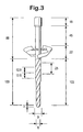
- Figure 3 represents a preferred stirrer, and includes preferred dimensions (in mm), for use in high throughput experimentation, especially reactions in autoclaves such as batch polymerisation.
- the stirrer shown in Figure 3 was used in a batch polypropylene experiment.
- 60g of seed bed (sodium chloride) was used as the fluidisation medium in a 270ml autoclave vessel using a stirrer as shown in Figure 2.
- the autoclave had a cylindrical outlet conduit that was approximately 100mm long with a valve at its base.
- the outlet conduit had an internal diameter of approximately 10mm at its top, which reduced to approximately 8mm at the valve.
- the flute width was approximately 9mm.
- polymer was formed. 40g of particulate polypropylene was made during an 80 minute test. During this time the stirrer was turning at 400rpm in a clockwise direction.
- the reactor was cooled to 45°C and 100ml of heptane was added to the autoclave.
- the reactor was pressurised to 0.3 bar using nitrogen and the stirrer was then turned in an anticlockwise direction at 400 rpm. After 10s the bottom valve of the autoclave was opened with the stirrer still turning anticlockwise.
- the polymer produced comprised particles of up to 2.5mm diameter. The particles were observed to have good morphology, and no evidence of grinding of the polymer particles with the seed bed material during discharge was observed.
- Example 2 60g of seed bed (sodium chloride) was used as the fluidisation medium in a 270ml autoclave vessel as in Example 1, but using an apparatus/stirrer not according to the present invention.
- the stirrer consisted of the same first part as in Example 1, but without a second part. After injection of the catalyst and addition of propylene gas, polymer was formed. 28g of particulate polypropylene was made during an 80 minute test. During this time the stirrer was turning at 400rpm in a clockwise direction.
- the reactor was cooled to 45°C and 100ml of heptane was added to the autoclave.
- the reactor was pressurised to 0.3 bar using nitrogen and the stirrer was then turned in an anticlockwise direction at 400 rpm. After 10s the bottom valve of the autoclave was opened with the stirrer still turning anticlockwise.
Landscapes
- Chemical & Material Sciences (AREA)
- Chemical Kinetics & Catalysis (AREA)
- Organic Chemistry (AREA)
- Engineering & Computer Science (AREA)
- Combustion & Propulsion (AREA)
- Mixers Of The Rotary Stirring Type (AREA)
Claims (10)
- Vorrichtung, umfassend einen Behälter, der ein Chargenreaktor mit von 1 ml und bis zu 500 ml Volumen ist, wobei der Behälter eine sich daraus erstreckende Leitung aufweist, einen Rührer, von dem ein Abschnitt (6, 100) zum Anordnen innerhalb der Leitung angepasst ist und von dem ein Abschnitt (11, 88) zum Anordnen innerhalb des Behälters angepasst ist, wobei der Rührer so angepasst ist, dass, wenn er in einer ersten Richtung gedreht wird, innerhalb der Leitung enthaltenes Material in einer Richtung zum Behälter hin gefördert wird, und, wenn er in einer zweiten Richtung gedreht wird, innerhalb der Leitung enthaltenes Material in einer Richtung weg vom Behälter durch die Leitung gefördert wird, sowie einen Rührerantrieb, der imstande ist, den Rührer sowohl in der ersten und der zweiten, entgegengesetzten Richtung zu drehen.
- Vorrichtung nach Anspruch 1, bei welcher der Rührer einen ersten Teil umfasst, der zum Verbinden mit dem Rührerantrieb angepasst ist und den Abschnitt des Rührers umfasst, der zum Anordnen innerhalb des Behälters angepasst ist, wobei der erste Teil weiter angepasst ist, um Material im Behälter zu rühren, wenn der Rührer gedreht wird, sowie einen zweiten Teil, der zum Verbinden mit dem ersten Teil angepasst ist und den Abschnitt des Rührers umfasst, der zum Anordnen innerhalb der Leitung angepasst ist.
- Vorrichtung nach Anspruch 2, bei welcher der erste Teil einen Schaft umfasst, um den herum ein oder mehrere Rührflügel angeordnet sind.
- Vorrichtung nach einem der vorangehenden Ansprüche, bei welcher der Abschnitt des Rührers, der zum Anordnen innerhalb der Leitung angepasst ist, eine oder mehrere Hohlkehlen umfasst, die einen schraubenförmigen Pfad um die Drehachse des Rührers herum beschreiben.
- Vorrichtung nach Anspruch 4, bei welcher die eine oder mehreren Hohlkehlen einen Schraubensteigungswinkel zwischen 20° und 70° aufweisen.
- Vorrichtung nach einem der vorangehenden Ansprüche, bei welcher der Abschnitt des Rührers, der zum Anordnen innerhalb der Leitung angepasst ist, derart ist, dass im Gebrauch innerhalb der Leitung derjenige Teilbereich an einer Stelle innerhalb der Leitung einen effektiven Durchmesser von mindestens 50 %, vorzugsweise im Bereich von 70 bis 90 % des Innendurchmessers der Leitung an dieser Stelle innerhalb der Leitung aufweist.
- Reaktionssystem mit hohem Durchsatz, umfassend 4 oder mehr Vorrichtungen nach einem der vorangehenden Ansprüche.
- Verfahren zum Rühren von einem oder mehreren Materialien in einer Vorrichtung, welches Verfahren die Verwendung einer Vorrichtung nach einem der Ansprüche 1 bis 6 oder eines Reaktionssystems mit hohem Durchsatz nach Anspruch 7 umfasst.
- Verfahren zum Rühren von einem oder mehreren Materialien in einer Vorrichtung, welches Verfahren umfasst(i) Bereitstellen einer Vorrichtung, umfassend einen Behälter mit einer sich daraus erstreckenden Leitung, welche Leitung ein Rohr von zylindrischem Innendurchmesser ist, an dessen Fuß sich ein Leitungsventil befindet, das es erlaubt, das untere Ende der Leitung zu verschließen, sowie einen Rührer, von dem ein Abschnitt zum Anordnen innerhalb der Leitung angepasst ist und von dem ein Abschnitt zum Anordnen innerhalb des Behälters angepasst ist, bei welcher der Rührer so angepasst ist, dass, wenn er in einer ersten Richtung gedreht wird, innerhalb der Leitung enthaltenes Material in einer Richtung zum Behälter hin gefördert wird, und, wenn er in einer zweiten Richtung gedreht wird, innerhalb der Leitung enthaltenes Material durch die Leitung in einer Richtung weg vom Behälter gefördert wird,(ii) Bereitstellen von einem oder mehreren Materialien im Behälter,(iii) Rühren des einen oder der mehreren Materialien unter Verwendung des Rührers, wobei bei geschlossenem Leitungsventil der Rührer ausgebildet ist, um sich in der ersten Richtung zu drehen, so dass der Rührer die Materialien im Behälter rührt, während der Abschnitt des Rührers, der zum Anordnen innerhalb der Leitung angepasst ist, sich so dreht, dass Material, das in die Leitung fallen kann, zurück in den Behälter gefördert wird, und(iv) Umkehren der Richtung des Rührers und Öffnen des Leitungsventils, wenn Material aus dem Behälter entfernt werden soll.
- Verfahren nach Anspruch 9, bei dem der Behälter ein Chargenreaktor mit von 1 ml und bis zu 500 ml Volumen ist.
Applications Claiming Priority (3)
| Application Number | Priority Date | Filing Date | Title |
|---|---|---|---|
| GBGB0305023.4A GB0305023D0 (en) | 2003-03-05 | 2003-03-05 | Apparatus and method |
| GB0305023 | 2003-03-05 | ||
| PCT/GB2004/000753 WO2004078330A1 (en) | 2003-03-05 | 2004-02-27 | Stirring apparatus and method of use of said apparatus |
Publications (2)
| Publication Number | Publication Date |
|---|---|
| EP1599280A1 EP1599280A1 (de) | 2005-11-30 |
| EP1599280B1 true EP1599280B1 (de) | 2006-05-10 |
Family
ID=9954159
Family Applications (1)
| Application Number | Title | Priority Date | Filing Date |
|---|---|---|---|
| EP04715369A Expired - Lifetime EP1599280B1 (de) | 2003-03-05 | 2004-02-27 | Rührvorrichtung und verfahren zur verwendung einer dergestalten vorrichtung |
Country Status (9)
| Country | Link |
|---|---|
| US (2) | US7775703B2 (de) |
| EP (1) | EP1599280B1 (de) |
| CN (1) | CN100381198C (de) |
| CA (1) | CA2518035A1 (de) |
| DE (1) | DE602004000864T2 (de) |
| ES (1) | ES2263140T3 (de) |
| GB (1) | GB0305023D0 (de) |
| WO (1) | WO2004078330A1 (de) |
| ZA (1) | ZA200506788B (de) |
Families Citing this family (5)
| Publication number | Priority date | Publication date | Assignee | Title |
|---|---|---|---|---|
| GB0501102D0 (en) | 2005-01-19 | 2005-02-23 | Bp Chem Int Ltd | Process |
| US20080298171A1 (en) * | 2007-05-08 | 2008-12-04 | David Scott Dunlop | Process for Mixing and Screening Liquid Compositions |
| GB2529471B (en) * | 2014-08-22 | 2016-10-19 | Challenging Innovation Ltd | Mixing apparatus |
| US20180311625A1 (en) * | 2015-12-03 | 2018-11-01 | Dow Global Technologies Llc | Dynamic mixer for viscous materials |
| EP3718409B1 (de) * | 2019-04-02 | 2024-09-11 | Ali Group S.r.l. - Carpigiani | Maschine und verfahren zur wärmebehandlung von flüssigen oder halbflüssigen lebensmittelprodukten |
Family Cites Families (12)
| Publication number | Priority date | Publication date | Assignee | Title |
|---|---|---|---|---|
| US376064A (en) * | 1888-01-10 | Samuel b | ||
| US626108A (en) * | 1899-05-30 | stuckel | ||
| US60145A (en) * | 1866-12-04 | hall covel | ||
| US1519664A (en) * | 1922-01-03 | 1924-12-16 | L S Fisher | Pump |
| US2718384A (en) * | 1954-03-04 | 1955-09-20 | Gordon F Schroeder | Molasses blender |
| US3173584A (en) * | 1962-11-15 | 1965-03-16 | Steve T Giavasis | Portable motor driven dispensing devices |
| NL172662C (nl) * | 1969-11-03 | 1983-10-03 | Du Pont | Werkwijze om polymeren te bereiden. |
| GB1325090A (en) | 1971-02-04 | 1973-08-01 | Stehning P R | Reaction vessels |
| CH573268A5 (de) * | 1971-02-04 | 1976-03-15 | Stehning Paul Rolf | |
| US3723020A (en) * | 1971-03-17 | 1973-03-27 | M Watanabe | Apparatus for transferring highly viscous material |
| US4690804A (en) * | 1983-07-15 | 1987-09-01 | Phillips Petroleum Company | Catalyst feed system |
| JP4102713B2 (ja) * | 2003-06-17 | 2008-06-18 | 株式会社神戸製鋼所 | 連続混練装置およびその運転方法 |
-
2003
- 2003-03-05 GB GBGB0305023.4A patent/GB0305023D0/en not_active Ceased
-
2004
- 2004-02-27 DE DE602004000864T patent/DE602004000864T2/de not_active Expired - Lifetime
- 2004-02-27 CN CNB2004800117132A patent/CN100381198C/zh not_active Expired - Fee Related
- 2004-02-27 ES ES04715369T patent/ES2263140T3/es not_active Expired - Lifetime
- 2004-02-27 EP EP04715369A patent/EP1599280B1/de not_active Expired - Lifetime
- 2004-02-27 US US10/547,846 patent/US7775703B2/en not_active Expired - Fee Related
- 2004-02-27 WO PCT/GB2004/000753 patent/WO2004078330A1/en not_active Ceased
- 2004-02-27 CA CA002518035A patent/CA2518035A1/en not_active Abandoned
-
2005
- 2005-08-24 ZA ZA200506788A patent/ZA200506788B/xx unknown
-
2010
- 2010-07-06 US US12/801,962 patent/US20100329948A1/en not_active Abandoned
Also Published As
| Publication number | Publication date |
|---|---|
| ZA200506788B (en) | 2006-05-31 |
| DE602004000864D1 (de) | 2006-06-14 |
| US20070002683A1 (en) | 2007-01-04 |
| DE602004000864T2 (de) | 2006-11-16 |
| EP1599280A1 (de) | 2005-11-30 |
| CA2518035A1 (en) | 2004-09-16 |
| US7775703B2 (en) | 2010-08-17 |
| ES2263140T3 (es) | 2006-12-01 |
| GB0305023D0 (en) | 2003-04-09 |
| WO2004078330A1 (en) | 2004-09-16 |
| CN100381198C (zh) | 2008-04-16 |
| US20100329948A1 (en) | 2010-12-30 |
| CN1780683A (zh) | 2006-05-31 |
Similar Documents
| Publication | Publication Date | Title |
|---|---|---|
| US20100329948A1 (en) | Stirring apparatus and method of use of said apparatus | |
| EP1208905B1 (de) | Gerührter Behälter zur Herstellung einer Feststoffe enthaltenden Suspension | |
| US4690804A (en) | Catalyst feed system | |
| CA1278916C (en) | Sludge processing | |
| US5439991A (en) | Method of mixing heterogeneous systems | |
| US11033874B2 (en) | Reaction chamber for a chemical reactor, and chemical reactor constructed therefrom | |
| KR101468470B1 (ko) | 올레핀의 액상 중합용 장치 | |
| CZ20002103A3 (en) | Agitator for subfluidized particulate bed in quench-cooled vapor phase polymerization reactor | |
| US20060104874A1 (en) | Segmented agitator reactor | |
| PL190126B1 (pl) | Urządzenie do przygotowywania substratu siarkowo-mocznikowego dla roztwarzania naturalnych fosforanów w instalacji przemysłowej do produkcji nawozów fosforowo-azotowych | |
| CA2297286A1 (en) | Method and equipment for mixing a powder with a liquid and for reacting a powder with a liquid | |
| US5899566A (en) | Reactor for corrosive reaction mixtures | |
| US5722529A (en) | Device for uniform draw-down, homogenization and continuous mixing of bulk solids from silos and stockpiles | |
| CA2338532C (en) | Process for introducing a solid catalyst into a fluidised or agitated vessel | |
| CN206597516U (zh) | 催化反应器 | |
| US3148037A (en) | Repeating chemical reactor apparatus | |
| EP0322441A1 (de) | Anordnung zur kontinuierlichen biologischen zersetzung von mineralien und deren konzentraten | |
| KR20170131152A (ko) | 화학 반응기 및 이를 이용한 올레핀 제조 방법 | |
| US20240207911A1 (en) | Systems and Methods for Treatment of Materials | |
| US4563665A (en) | Method for mixing and transferring polymer-coated catalyst compositions | |
| US3125420A (en) | Compact reactor for production of fertilizer solids | |
| KR20170130966A (ko) | 화학 반응기 및 이를 이용한 올레핀 제조 방법 | |
| AU2023446742B8 (en) | Precipitation system for hydrometallurgical processing of laterite nickel ore | |
| EP1580151A1 (de) | Ventil | |
| van den Bergh | Removing the uncertainty in solids mixer selection |
Legal Events
| Date | Code | Title | Description |
|---|---|---|---|
| PUAI | Public reference made under article 153(3) epc to a published international application that has entered the european phase |
Free format text: ORIGINAL CODE: 0009012 |
|
| 17P | Request for examination filed |
Effective date: 20050819 |
|
| AK | Designated contracting states |
Kind code of ref document: A1 Designated state(s): AT BE BG CH CY CZ DE DK EE ES FI FR GB GR HU IE IT LI LU MC NL PT RO SE SI SK TR |
|
| AX | Request for extension of the european patent |
Extension state: AL LT LV MK |
|
| GRAP | Despatch of communication of intention to grant a patent |
Free format text: ORIGINAL CODE: EPIDOSNIGR1 |
|
| RAP1 | Party data changed (applicant data changed or rights of an application transferred) |
Owner name: INNOVENE EUROPE LIMITED |
|
| GRAS | Grant fee paid |
Free format text: ORIGINAL CODE: EPIDOSNIGR3 |
|
| RAP1 | Party data changed (applicant data changed or rights of an application transferred) |
Owner name: INNOVENE EUROPE LIMITED |
|
| GRAA | (expected) grant |
Free format text: ORIGINAL CODE: 0009210 |
|
| AK | Designated contracting states |
Kind code of ref document: B1 Designated state(s): AT BE BG CH CY CZ DE DK EE ES FI FR GB GR HU IE IT LI LU MC NL PT RO SE SI SK TR |
|
| PG25 | Lapsed in a contracting state [announced via postgrant information from national office to epo] |
Ref country code: IT Free format text: LAPSE BECAUSE OF FAILURE TO SUBMIT A TRANSLATION OF THE DESCRIPTION OR TO PAY THE FEE WITHIN THE PRESCRIBED TIME-LIMIT;WARNING: LAPSES OF ITALIAN PATENTS WITH EFFECTIVE DATE BEFORE 2007 MAY HAVE OCCURRED AT ANY TIME BEFORE 2007. THE CORRECT EFFECTIVE DATE MAY BE DIFFERENT FROM THE ONE RECORDED. Effective date: 20060510 Ref country code: SI Free format text: LAPSE BECAUSE OF FAILURE TO SUBMIT A TRANSLATION OF THE DESCRIPTION OR TO PAY THE FEE WITHIN THE PRESCRIBED TIME-LIMIT Effective date: 20060510 Ref country code: SK Free format text: LAPSE BECAUSE OF FAILURE TO SUBMIT A TRANSLATION OF THE DESCRIPTION OR TO PAY THE FEE WITHIN THE PRESCRIBED TIME-LIMIT Effective date: 20060510 Ref country code: RO Free format text: LAPSE BECAUSE OF FAILURE TO SUBMIT A TRANSLATION OF THE DESCRIPTION OR TO PAY THE FEE WITHIN THE PRESCRIBED TIME-LIMIT Effective date: 20060510 Ref country code: FI Free format text: LAPSE BECAUSE OF FAILURE TO SUBMIT A TRANSLATION OF THE DESCRIPTION OR TO PAY THE FEE WITHIN THE PRESCRIBED TIME-LIMIT Effective date: 20060510 |
|
| REG | Reference to a national code |
Ref country code: GB Ref legal event code: FG4D |
|
| REG | Reference to a national code |
Ref country code: CH Ref legal event code: EP |
|
| DAX | Request for extension of the european patent (deleted) | ||
| REF | Corresponds to: |
Ref document number: 602004000864 Country of ref document: DE Date of ref document: 20060614 Kind code of ref document: P |
|
| REG | Reference to a national code |
Ref country code: IE Ref legal event code: FG4D |
|
| REG | Reference to a national code |
Ref country code: CH Ref legal event code: NV Representative=s name: KIRKER & CIE SA |
|
| PG25 | Lapsed in a contracting state [announced via postgrant information from national office to epo] |
Ref country code: DK Free format text: LAPSE BECAUSE OF FAILURE TO SUBMIT A TRANSLATION OF THE DESCRIPTION OR TO PAY THE FEE WITHIN THE PRESCRIBED TIME-LIMIT Effective date: 20060810 Ref country code: SE Free format text: LAPSE BECAUSE OF FAILURE TO SUBMIT A TRANSLATION OF THE DESCRIPTION OR TO PAY THE FEE WITHIN THE PRESCRIBED TIME-LIMIT Effective date: 20060810 |
|
| RAP2 | Party data changed (patent owner data changed or rights of a patent transferred) |
Owner name: INEOS EUROPE LIMITED |
|
| NLT2 | Nl: modifications (of names), taken from the european patent patent bulletin |
Owner name: INEOS EUROPE LIMITED Effective date: 20060816 |
|
| PG25 | Lapsed in a contracting state [announced via postgrant information from national office to epo] |
Ref country code: PT Free format text: LAPSE BECAUSE OF FAILURE TO SUBMIT A TRANSLATION OF THE DESCRIPTION OR TO PAY THE FEE WITHIN THE PRESCRIBED TIME-LIMIT Effective date: 20061010 |
|
| ET | Fr: translation filed | ||
| REG | Reference to a national code |
Ref country code: ES Ref legal event code: FG2A Ref document number: 2263140 Country of ref document: ES Kind code of ref document: T3 |
|
| PG25 | Lapsed in a contracting state [announced via postgrant information from national office to epo] |
Ref country code: MC Free format text: LAPSE BECAUSE OF NON-PAYMENT OF DUE FEES Effective date: 20070228 |
|
| PLBE | No opposition filed within time limit |
Free format text: ORIGINAL CODE: 0009261 |
|
| STAA | Information on the status of an ep patent application or granted ep patent |
Free format text: STATUS: NO OPPOSITION FILED WITHIN TIME LIMIT |
|
| RAP2 | Party data changed (patent owner data changed or rights of a patent transferred) |
Owner name: INEOS EUROPE LIMITED |
|
| 26N | No opposition filed |
Effective date: 20070213 |
|
| REG | Reference to a national code |
Ref country code: FR Ref legal event code: CD Ref country code: FR Ref legal event code: CA |
|
| NLT1 | Nl: modifications of names registered in virtue of documents presented to the patent office pursuant to art. 16 a, paragraph 1 |
Owner name: INEOS EUROPE LIMITED |
|
| NLT2 | Nl: modifications (of names), taken from the european patent patent bulletin |
Owner name: INEOS EUROPE LIMITED Effective date: 20070411 |
|
| BECA | Be: change of holder's address |
Owner name: *INEOS EUROPE LTDHAWKSLEASE, CHAPEL LANE, LYNDHURS Effective date: 20060510 |
|
| BECN | Be: change of holder's name |
Owner name: *INEOS EUROPE LTD Effective date: 20060510 |
|
| PG25 | Lapsed in a contracting state [announced via postgrant information from national office to epo] |
Ref country code: IE Free format text: LAPSE BECAUSE OF NON-PAYMENT OF DUE FEES Effective date: 20070227 |
|
| PG25 | Lapsed in a contracting state [announced via postgrant information from national office to epo] |
Ref country code: GR Free format text: LAPSE BECAUSE OF FAILURE TO SUBMIT A TRANSLATION OF THE DESCRIPTION OR TO PAY THE FEE WITHIN THE PRESCRIBED TIME-LIMIT Effective date: 20060811 |
|
| PG25 | Lapsed in a contracting state [announced via postgrant information from national office to epo] |
Ref country code: BG Free format text: LAPSE BECAUSE OF FAILURE TO SUBMIT A TRANSLATION OF THE DESCRIPTION OR TO PAY THE FEE WITHIN THE PRESCRIBED TIME-LIMIT Effective date: 20060810 |
|
| PG25 | Lapsed in a contracting state [announced via postgrant information from national office to epo] |
Ref country code: EE Free format text: LAPSE BECAUSE OF FAILURE TO SUBMIT A TRANSLATION OF THE DESCRIPTION OR TO PAY THE FEE WITHIN THE PRESCRIBED TIME-LIMIT Effective date: 20060510 |
|
| PG25 | Lapsed in a contracting state [announced via postgrant information from national office to epo] |
Ref country code: LU Free format text: LAPSE BECAUSE OF NON-PAYMENT OF DUE FEES Effective date: 20070227 Ref country code: CY Free format text: LAPSE BECAUSE OF FAILURE TO SUBMIT A TRANSLATION OF THE DESCRIPTION OR TO PAY THE FEE WITHIN THE PRESCRIBED TIME-LIMIT Effective date: 20060510 |
|
| PG25 | Lapsed in a contracting state [announced via postgrant information from national office to epo] |
Ref country code: HU Free format text: LAPSE BECAUSE OF FAILURE TO SUBMIT A TRANSLATION OF THE DESCRIPTION OR TO PAY THE FEE WITHIN THE PRESCRIBED TIME-LIMIT Effective date: 20061111 Ref country code: TR Free format text: LAPSE BECAUSE OF FAILURE TO SUBMIT A TRANSLATION OF THE DESCRIPTION OR TO PAY THE FEE WITHIN THE PRESCRIBED TIME-LIMIT Effective date: 20060510 |
|
| PGFP | Annual fee paid to national office [announced via postgrant information from national office to epo] |
Ref country code: FR Payment date: 20110309 Year of fee payment: 8 Ref country code: IT Payment date: 20110224 Year of fee payment: 8 Ref country code: CH Payment date: 20110223 Year of fee payment: 8 Ref country code: CZ Payment date: 20110204 Year of fee payment: 8 |
|
| PGFP | Annual fee paid to national office [announced via postgrant information from national office to epo] |
Ref country code: GB Payment date: 20110223 Year of fee payment: 8 Ref country code: BE Payment date: 20110224 Year of fee payment: 8 Ref country code: ES Payment date: 20110224 Year of fee payment: 8 |
|
| REG | Reference to a national code |
Ref country code: GB Ref legal event code: 732E Free format text: REGISTERED BETWEEN 20111201 AND 20111207 |
|
| BERE | Be: lapsed |
Owner name: *INEOS EUROPE LTD Effective date: 20120228 |
|
| REG | Reference to a national code |
Ref country code: CH Ref legal event code: PL |
|
| GBPC | Gb: european patent ceased through non-payment of renewal fee |
Effective date: 20120227 |
|
| PG25 | Lapsed in a contracting state [announced via postgrant information from national office to epo] |
Ref country code: CH Free format text: LAPSE BECAUSE OF NON-PAYMENT OF DUE FEES Effective date: 20120229 Ref country code: LI Free format text: LAPSE BECAUSE OF NON-PAYMENT OF DUE FEES Effective date: 20120229 Ref country code: CZ Free format text: LAPSE BECAUSE OF NON-PAYMENT OF DUE FEES Effective date: 20120227 |
|
| REG | Reference to a national code |
Ref country code: FR Ref legal event code: ST Effective date: 20121031 |
|
| PG25 | Lapsed in a contracting state [announced via postgrant information from national office to epo] |
Ref country code: BE Free format text: LAPSE BECAUSE OF NON-PAYMENT OF DUE FEES Effective date: 20120228 |
|
| PG25 | Lapsed in a contracting state [announced via postgrant information from national office to epo] |
Ref country code: FR Free format text: LAPSE BECAUSE OF NON-PAYMENT OF DUE FEES Effective date: 20120229 Ref country code: GB Free format text: LAPSE BECAUSE OF NON-PAYMENT OF DUE FEES Effective date: 20120227 |
|
| REG | Reference to a national code |
Ref country code: ES Ref legal event code: FD2A Effective date: 20130708 |
|
| PG25 | Lapsed in a contracting state [announced via postgrant information from national office to epo] |
Ref country code: ES Free format text: LAPSE BECAUSE OF NON-PAYMENT OF DUE FEES Effective date: 20120228 |
|
| PG25 | Lapsed in a contracting state [announced via postgrant information from national office to epo] |
Ref country code: IT Free format text: LAPSE BECAUSE OF NON-PAYMENT OF DUE FEES Effective date: 20120227 |
|
| REG | Reference to a national code |
Ref country code: DE Ref legal event code: R082 Ref document number: 602004000864 Country of ref document: DE Representative=s name: LEDERER & KELLER, DE |
|
| REG | Reference to a national code |
Ref country code: DE Ref legal event code: R082 Ref document number: 602004000864 Country of ref document: DE Representative=s name: LEDERER & KELLER, DE Effective date: 20131204 Ref country code: DE Ref legal event code: R081 Ref document number: 602004000864 Country of ref document: DE Owner name: INEOS EUROPE AG, CH Free format text: FORMER OWNER: INEOS EUROPE LTD.,, LYNDHURST, BG Effective date: 20131204 Ref country code: DE Ref legal event code: R082 Ref document number: 602004000864 Country of ref document: DE Representative=s name: LEDERER & KELLER PATENTANWAELTE PARTNERSCHAFT , DE Effective date: 20131204 Ref country code: DE Ref legal event code: R081 Ref document number: 602004000864 Country of ref document: DE Owner name: INEOS EUROPE AG, ROLLE, CH Free format text: FORMER OWNER: INEOS EUROPE LTD.,, LYNDHURST, HAMPSHIRE, BG Effective date: 20131204 |
|
| REG | Reference to a national code |
Ref country code: NL Ref legal event code: SD Effective date: 20140224 |
|
| REG | Reference to a national code |
Ref country code: AT Ref legal event code: MK05 Ref document number: 676953 Country of ref document: AT Kind code of ref document: T Effective date: 20060510 |
|
| PG25 | Lapsed in a contracting state [announced via postgrant information from national office to epo] |
Ref country code: AT Free format text: LAPSE BECAUSE OF FAILURE TO SUBMIT A TRANSLATION OF THE DESCRIPTION OR TO PAY THE FEE WITHIN THE PRESCRIBED TIME-LIMIT Effective date: 20060510 |
|
| PGFP | Annual fee paid to national office [announced via postgrant information from national office to epo] |
Ref country code: DE Payment date: 20150226 Year of fee payment: 12 Ref country code: NL Payment date: 20150225 Year of fee payment: 12 |
|
| REG | Reference to a national code |
Ref country code: DE Ref legal event code: R119 Ref document number: 602004000864 Country of ref document: DE |
|
| REG | Reference to a national code |
Ref country code: NL Ref legal event code: MM Effective date: 20160301 |
|
| PG25 | Lapsed in a contracting state [announced via postgrant information from national office to epo] |
Ref country code: NL Free format text: LAPSE BECAUSE OF NON-PAYMENT OF DUE FEES Effective date: 20160301 Ref country code: DE Free format text: LAPSE BECAUSE OF NON-PAYMENT OF DUE FEES Effective date: 20160901 |