EP1599133B1 - Verfahren und gerät zur abschätzung der ventrikelnachbelastung basiert auf ventrickeldruckmessungen - Google Patents
Verfahren und gerät zur abschätzung der ventrikelnachbelastung basiert auf ventrickeldruckmessungen Download PDFInfo
- Publication number
- EP1599133B1 EP1599133B1 EP04711883A EP04711883A EP1599133B1 EP 1599133 B1 EP1599133 B1 EP 1599133B1 EP 04711883 A EP04711883 A EP 04711883A EP 04711883 A EP04711883 A EP 04711883A EP 1599133 B1 EP1599133 B1 EP 1599133B1
- Authority
- EP
- European Patent Office
- Prior art keywords
- pressure
- ventricular
- index
- blood
- afterload
- Prior art date
- Legal status (The legal status is an assumption and is not a legal conclusion. Google has not performed a legal analysis and makes no representation as to the accuracy of the status listed.)
- Expired - Lifetime
Links
Images





Classifications
-
- A—HUMAN NECESSITIES
- A61—MEDICAL OR VETERINARY SCIENCE; HYGIENE
- A61B—DIAGNOSIS; SURGERY; IDENTIFICATION
- A61B5/00—Measuring for diagnostic purposes; Identification of persons
- A61B5/02—Detecting, measuring or recording for evaluating the cardiovascular system, e.g. pulse, heart rate, blood pressure or blood flow
- A61B5/021—Measuring pressure in heart or blood vessels
- A61B5/0215—Measuring pressure in heart or blood vessels by means inserted into the body
-
- A—HUMAN NECESSITIES
- A61—MEDICAL OR VETERINARY SCIENCE; HYGIENE
- A61B—DIAGNOSIS; SURGERY; IDENTIFICATION
- A61B5/00—Measuring for diagnostic purposes; Identification of persons
- A61B5/72—Signal processing specially adapted for physiological signals or for diagnostic purposes
- A61B5/7235—Details of waveform analysis
- A61B5/7239—Details of waveform analysis using differentiation including higher order derivatives
-
- A—HUMAN NECESSITIES
- A61—MEDICAL OR VETERINARY SCIENCE; HYGIENE
- A61N—ELECTROTHERAPY; MAGNETOTHERAPY; RADIATION THERAPY; ULTRASOUND THERAPY
- A61N1/00—Electrotherapy; Circuits therefor
- A61N1/18—Applying electric currents by contact electrodes
- A61N1/32—Applying electric currents by contact electrodes alternating or intermittent currents
- A61N1/36—Applying electric currents by contact electrodes alternating or intermittent currents for stimulation
- A61N1/362—Heart stimulators
- A61N1/365—Heart stimulators controlled by a physiological parameter, e.g. heart potential
- A61N1/36514—Heart stimulators controlled by a physiological parameter, e.g. heart potential controlled by a physiological quantity other than heart potential, e.g. blood pressure
- A61N1/36564—Heart stimulators controlled by a physiological parameter, e.g. heart potential controlled by a physiological quantity other than heart potential, e.g. blood pressure controlled by blood pressure
Definitions
- This invention relates to apparatus for estimating ventricular afterload presenting resistance to ejection of blood from a ventricle during a blood ejection phase of the ventricle from measurements of ventricular pressure.
- Almost any cardiac disorder that impairs the ability of the ventricle to eject blood suffers a progression toward an inexorable deterioration of cardiac structure and function, producing the complex clinical syndrome of heart failure (HF), which is a common medical condition that afflicts approximately 1.5 to 2.0% of the population (4.8 million people in the United States) and which has a risk of death of 5 to 10% annually in patients with mild symptoms and increases to as high as 30 to 40% annually in patients with advanced disease, as, set for the in U.S. Patent No. 6,440,078 .
- HF complex clinical syndrome of heart failure
- AV atrioventricular
- DDD atrioventricular
- DDDR atrioventricular
- DDDR atrioventricular
- Other companies have prescribed implantation of conventional, atrioventricular (AV) synchronous pacing systems, including DDD and DDDR pacing systems, marketed by Medtronic, Inc. and other companies, in certain patients for treatment of HF symptoms.
- Certain patient groups suffering HF symptoms with or without bradycardia tend to do much better hemodynamically with AV synchronous pacing due to the added contribution of atrial contraction to ventricular filling and subsequent contraction.
- fixed or physiologic sensor driven rate responsive pacing in such patients does not always lead to improvement in cardiac output and alleviation of the symptoms attendant to such disease processes because it is difficult to assess the degree of compromise of cardiac output caused by HF and to determine the pacing parameters that are optimal for maximizing cardiac output, particularly the AV delay. Determining an optimal AV delay requires performing echocardiography studies or obtaining pressure data involving an extensive patient work-up as
- Holter monitors can determine if there is any accompanying electrical instability or arrhythmia.
- Holter monitors cannot measure blood pressure or other indicia of mechanical heart function. Consequently, implantable physiologic cardiac monitors for monitoring the mechanical and/or electrical heart function have been proposed and, in some cases, implemented for deriving and storing EGM and mechanical performance data over a prolonged time.
- the Medtronic® CHRONICLE® Implantable Hemodynamic Monitor (IHM) system comprises a CHRONICLE@ Model 9520 IHM of the type described in commonly assigned U.S. Patent No. 5,368,040 coupled with a Model 4328A pressure sensor lead that senses blood pressure within a heart chamber and the EGM of the heart using a pressure sensing transducer of the type disclosed in commonly assigned U.S. Patent No. 5,564,434 .
- the CHRONICLE@ Model 9520 IHM measures absolute blood pressure, and the patient is also provided with an externally worn Medtronic® Model No. 2955HF atmospheric pressure reference monitor of the type described in commonly assigned U.S. Patent No. 5,819,735 to record contemporaneous atmospheric pressure values.
- the CHRONICLE@ Model 9520 IHM can be programmed to measure the RV systolic pressure (maximum pressure in a sampling window), RV diastolic pressure (first sample in a sample window), pulse pressure (RV systolic - RV diastolic pressure), pre-ejection interval (PEI), systolic time interval (STI), peak positive and negative dP/dt, estimated pulmonary artery diastolic pressure (ePAD), patient activity level, and heart rate.
- the pressure parameters are sampled at a sampling rate of 256 samples per second, digitized and stored in memory registers.
- the samples are taken in a sampling window of each heart cycle of 20 ms through 500 ms following the detection of an R-wave, unless the R-wave occurs earlier.
- the Model 9520 IHM is programmed and interrogated employing an external Model 9790 programmer or a PC with CHRONICLE@ software to accumulate trend data stored in a large FIFO buffer in RAM at a programmable resolution.
- the buffer can be filled in approximately an hour using the highest resolution or in about two months using the lowest resolution.
- the memory buffers of the CHRONICLE® Model 9520 IHM and the externally worn Medtronic® Model No. 2955HF atmospheric pressure reference monitor can be interrogated to telemetry transmit the measured and stored pressure and other data, thereby emptying the buffers, to a nearby Model 9521HF Interactive Remote Monitor for temporary storage of the data.
- the Model 9521HF Interactive Remote Monitor external medical device periodically transmits accumulated data to a remote data processing center that processes the data to develop trend data that the attending physician can review with other patient data derived in patient examinations and interviews to assess the HF state.
- the IHM system can be used in the clinical setting to make and observe real-time blood pressure and heart rate measurements while the patient is at rest or is exercising on a treadmill.
- the patient data can be stored in external clinical systems for historic or benchmark comparative uses over time.
- an IHM system implanted in patients suffering from cardiac arrhythmias or HF can accumulate date and time stamped blood pressure data that can be of use in determining the condition of the heart over an extended period of time and while the patient is clinically tested or is engaged in daily activities.
- Various other IHM functions and uses of EGM, pressure and other parameter data accumulated in an IHM are disclosed in U.S. Patent Nos. 5,417,717 , 6,104,949 , 6,155,267 , 6,280,409 , 6,275,707 , 6,309,350 , and 6,438,408 , for example.
- U.S. Patent No. 5,758,652 describes an implantable absolute blood pressure monitor and method for measuring the heart condition of a patient by utilizing blood pressure signals filtered to remove respiratory effects.
- One indicia of an early stage of chronic HF comprises ventricular afterload, which has not, to my knowledge been measured employing an IMD.
- Ventricular afterload may be defined as the mechanical force opposing ventricular ejection, as for example described by W. R. Milnor, "Arterial Impedance as Ventricular Load” Circulation Research, 1975;36:565-70 .
- This mechanical opposition of the flow of the viscous blood through the visco-elastic arterial system has two major mechanical components determined by the mechanical properties of the arterial system including hydraulic resistance and arterial compliance.
- Hydraulic resistance is a function of several factors including the smooth muscle tone of the arterial system that determines arterial dimension, the dimensions and patency of the aortic or pulmonic valve, the geometry of the ventricular outflow tract, thickness of the ventricular myocardium, the length of the arterial vessels and the viscosity of the blood. Hydraulic resistance is proportional to ventricular afterload and can be described in general by Poisuelle's law or by Ohm's law, which states that systemic vascular resistance (also referred to as total peripheral resistance) is equal to the difference between mean arterial pressure and central venous pressure divided by cardiac output. Hydraulic resistance is typically estimated clinically by invasive or non-invasive estimates of mean arterial pressure and cardiac output.
- Arterial compliance describes the ability of the arterial blood vessels to store a portion of the energy delivered to the arterial system by the ventricles during systole and return that energy to the arterial blood during ventricular diastole in order to maintain diastolic arterial blood pressure and flow. Arterial compliance is inversely proportional to ventricular afterload. Clinical estimates of arterial compliance are difficult to measure. It is occasionally approximated by aortic distensibility, or the change in aortic pressure divided by the change in aortic cross-sectional area.
- Ventricular afterload including both arterial resistance and arterial compliance
- the mathematical solution to these models requires measurement of both aortic blood pressure and flow.
- ventricular arterial coupling describes the mechanical relationship between the ventricles and the arterial system during ventricular ejection as described for example by M.R. Starling, "Left Ventricular-arterial Coupling Relations in the Normal Human Heart", Am. Heart J., 1993;125:1659-66 .
- Cardiovascular function may be maintained even if ventricular contractile function is reduced by a compensatory decrease in ventricular afterload (either by decreased resistance, increased compliance or both).
- administration of nitroglycerin during an episode of myocardial ischemia can maintain cardiac output despite decreased ventricular contractility by reducing arterial tone, increasing arterial compliance and hence decreasing ventricular afterload.
- Measurement of ventricular arterial coupling parameters involves measurement of both ventricular pressure and volume.
- Regional or global changes in ventricular afterload including arterial resistance and compliance may alter patterns of arterial wave reflection. These changes in arterial wave reflection patterns may be manifest by changes in pressure signals measured in the arteries or ventricles as demonstrated for example by M. O'Rourke, "Coupling Between the Left Ventricle and Arterial System in Hypertension", Eur. Heart J. 1990;11(G):24-28 .
- changes in the morphometry of ventricular or arterial blood pressure signals can indicate changes in the resistive and compliant properties of the arterial system and hence can indicate changes in ventricular afterload.
- HF cardiovascular function
- right or left ventricular afterload patients with acute HF, particularly as a complication of acute myocardial infarction or as an acute exacerbation of a previously compensated chronic HF, have a high mortality rate of about 30% within the first 12 months.
- a proper evaluation of ventricular afterload is extremely important for diagnostic purposes to assess the severity of the process and as a guide for the inotropic, vasodilator, or diuretic therapy.
- ventricular afterload such as systolic arterial blood pressure, systemic vascular resistance or peak ventricular wall stress, with the serious limitations that these parameters have, since they ignore arterial compliance.
- Ventricular afterload may be estimated using aortic (or pulmonary) input impedance. However, this index requires the measurement of both pressure and flow and is difficult to interpret clinically.
- ventricular afterload Multiple clinical pathologies may result in acute or chronic changes in ventricular afterload including valvular disease, hypertension, ventricular hypertrophy, hypertrophic cardiomyopathy, atheroschlerotic plaque formation, arterial thrombus, systemic shock, etc.
- any vasoactive substance that affects arterial or venous tone such as but not limited to nitro-glycerin, sodium nitro-prusside, neosynephrine, or epinephrine, can dramatically alter ventricular afterload.
- the ability to monitor and minimize ventricular afterload by minimizing arterial resistance, maximizing arterial compliance and controlling the timing of reflected waves by pharmacological or other methods is extremely important.
- cardiovascular function or the ability of the heart and vasculature to provide the nutritional needs of all the peripheral tissues, depends on the complex interaction of four distinct mechanical systems. These include the visco-elastic mechanical properties of the veno-atrial (or preload) system), the diastolic mechanical properties of the ventricles, the systolic mechanical properties of the ventricles, and the visco-elastic properties of the arterial (or ventricular afterload) system.
- the present invention is therefore directed to apparatus for developing estimates of the ventricular afterload derived from ventricular pressure measurements.
- the devices of the invention are characterized in the independent claims, whereas preferred embodiments of the invention are stated in the sub-claims.
- the invention has the important advantage of assessing a heart failure state from acute or chronically accumulated estimates of ventricular afterload preferably by an implantable medical device (IMD).
- IMD implantable medical device
- the estimates of the ventricular afterload may be used to quantify the current state of cardiovascular function, to discern changes in the state of cardiovascular function over time, and to select or alter a therapy delivered by an IMD to optimize cardiovascular function of patients experiencing heart failure, hypertension and other clinical pathologies as described above.
- certain estimates of ventricular afterload are derived from certain measured absolute right or left ventricular blood pressure values and from the derivatives of certain measured absolute right or left ventricular blood pressure values.
- the ventricular blood pressure waveform is sampled and digitized at a predetermined sampling rate.
- the sampled pressure data values are processed and compared in real time to determine the peak positive pressure P b among the sampled pressure values, the peak positive derivative pressure dP/dt PP , and the peak negative derivative pressure dP/dt PN of the pressure waveform.
- the sample time (t b ) associated with the sampled peak positive pressure P b , the sample time (t a ) associated with the peak positive derivative pressure dP/dt PP , and the sample time (t c ) associated with the peak negative derivative pressure dP/dt PN of the pressure beat are determined.
- the absolute blood pressure at time t c is also determined as pressure P c .
- the value of the index ⁇ of the relative timing of peak positive pressure P b is proportional to ventricular afterload and is limited to values between 0 and 1.
- This index ⁇ describes the approximate linear slope of the descent of ventricular pressure from peak pressure P b to P C .
- the magnitude of the index ⁇ is proportional to ventricular afterload. That is, a higher magnitude of the index ⁇ implies a higher ventricular afterload.
- the magnitude of the index ⁇ has no upper limit.
- index ⁇ of the relative timing of peak positive pressure P b and the index ⁇ of the slope of the early ejection pressure are two independent and alternative, but interrelated methods of quantifying ventricular afterload from right or left ventricular pressure measurements.
- each index is stored in memory within the IMD for uplink telemetry transmission at a later time to an external medical device for analysis.
- the changes in ventricular afterload in response to drug or electrical stimulation therapies prescribed to reduce HF or hypertension symptoms, for example, can be assessed from changes in index ⁇ of the relative timing of peak positive pressure P b and the index ⁇ of the slope of the early ejection pressure.
- a drug therapy or a therapy delivered by an IMD would be changed so as to minimize the indices ⁇ and/or ⁇ .
- a pacing mode or pacing parameter of an implantable pacing system providing single chamber pacing or dual chamber pacing or right and left heart pacing can be varied so that indices ⁇ and/or ⁇ can be determined and compared to determine the optimal pacing rate that results in the minimal values of the indices ⁇ and/or ⁇ .
- the estimates of the ventricular afterload are advantageously derived from ventricular pressure measurements made by an IMD.
- the indices of the ventricular afterload derived from ventricular pressure measurements can be advantageously performed acutely to diagnose patients employing temporarily implanted pressure measurement instruments.
- an IMD incorporating the present invention may be utilized to obtain and store the aforementioned indices along with other patient data over a period of time.
- the treating physician is able to initiate uplink telemetry of the stored patient data in order to review it to make an assessment of the HF state of the patient's heart from the estimated index data collected over time.
- the physician can then determine whether a particular therapy is appropriate, prescribe the therapy for a period of time while again accumulating the stored patient data for a later review and assessment to determine whether the applied therapy is beneficial or not, thereby enabling periodic changes in therapy, if appropriate.
- the illustrated embodiment of the invention is embodied in an IHM but can be incorporated into therapy delivery IMDs as noted above, e.g., an AV sequential, bi-atrial and bi-ventricular, pacing system operating in demand, atrial tracking, and triggered pacing for restoring synchrony in depolarization and contraction of left and right ventricles in synchronization with atrial sensed and paced events for treating HF and/or bradycardia.
- the embodiments of the invention can therefore comprise multichamber pacing systems programmable to operate as a two, three or four channel pacing system having an AV synchronous operating mode for restoring upper and lower heart chamber synchronization and right and left atrial and/or ventricular chamber depolarization synchrony.
- Additional therapies include drug therapies and other electrical stimulation therapies, including PESP stimulation.
- the assessment of HF state can be taken into account in setting parameters of detection or classification of tachyarrhythmias and the therapies that are delivered.
- the exemplary system illustrated in FIGS. 1 and 2 comprises an exemplary IMD 100 and blood pressure lead 12 locating a blood pressure sensor 20 within the right ventricle near the outflow tract of the patient's heart 10.
- the exemplary system further comprises an externally worn or otherwise carried atmospheric pressure reference monitor 200 to record contemporaneous atmospheric pressure values, and an external programmer 300.
- External programmer 300 is used to communicate with the IMD 100 and the atmospheric pressure reference monitor 200 in order to program the operating modes and parameters of IMD 100 or interrogate the data stored in memory of the IMD 100 and atmospheric pressure reference monitor 200.
- the IMD 100 preferably comprises the above-referenced Medtronic® CHRONICLE@ Model 9520 IHM having the capabilities of deriving and storing the above-referenced pressure data as well as heart rate data from the sensed ventricular EGM and patient activity level as monitored by an activity sensor 106.
- the pressure sensor lead 12 preferably comprises the above-referenced Model 4328A pressure sensor lead that senses blood pressure using a pressure sensing transducer 20 of the type disclosed in commonly assigned U.S. Patent No. 5,564,434 .
- the pressure sensor lead 12 also incorporates a distal EGM sense electrode 26 and conventional soft pliant tines that provide passive fixation of the sense electrode 26 into the ventricular apex in a manner well known in the art.
- the proximal connector assembly of pressure sensor lead 12 is configured in conformance with IS-1 standards for bipolar pacing leads and is fitted into a conforming bore of the connector header 180 or IMD 100 in the conventional manner.
- the EGM of the heart particularly the R-waves of the PQRST complex, is sensed between the active distal tip electrode 26 and the indifferent electrode formed by the hermetically sealed housing or can 178 of IMD 100 in a conventional unipolar configuration.
- other possible configurations of the IMD 100 can provide cardioversion/defibrillation and/or pacing therapies requiring additional implantable cardiac leads and electrodes preferably for synchronously pacing upper and lower and right and left heart chambers for improving cardiac output in patients suffering from HF.
- the CHRONICLE@ Model 9520 IHM measures absolute blood pressure, and so the patient is also provided with the atmospheric pressure reference monitor 200, e.g., the above-referenced Medtronic® Model No. 2955HF atmospheric pressure reference monitor.
- Atmospheric pressure reference monitor 200 is schematically depicted as worn on the patient's wrist, optionally including a timepiece function 250, but it may take other portable configurations so that it can accompany the patient in the patient's daily routine.
- the functions of an exemplary atmospheric pressure reference monitor 200 in relation to the IHM 100 and programmer 300 are disclosed in commonly assigned U.S. Patent No. 5,904,708 .
- the derivation and storage of atmospheric pressure values by the atmospheric pressure reference monitor 200 are not necessary to practice the present invention, since the above-identified time points and relative pressure values are sufficient to solve the equations for estimating the indices ⁇ and ⁇ .
- the index ⁇ of the relative timing of peak positive pressure P b and the index ⁇ of the slope of the early ejection pressure can be derived directly from the sampled right and left ventricular pressure signals.
- the estimation of the index ⁇ of the relative timing of peak positive pressure P b and the index ⁇ of the slope of the early ejection pressure can be performed using the above-identified IHM 100 in a system that happens to also include the atmospheric pressure reference monitor 200.
- Uplink telemetry (UT) and downlink telemetry (DT) transmissions between an RF telemetry antenna 134 of the IMD 100 (schematically illustrated as extending from the connector 180 of the IMD 100) and a telemetry antenna 334 of the external programmer 300 are schematically illustrated in FIG. 1 .
- UT and DT transmissions between an RF telemetry antenna 234 of the atmospheric pressure reference monitor 200 and the telemetry antenna 334 of the external programmer 300 are also illustrated in FIG. 1 .
- a direct cable or plug-in connection can be made between ports of the atmospheric pressure reference monitor 200 and the external programmer 300 instead of employing the depicted UT and DT transmissions between the RF telemetry antennas 234 and 334 when atmospheric pressure data is to be read from memory in the atmospheric pressure reference monitor 200.
- the RF telemetry system preferably operates at a long range of about 2 meters or more in a relatively high frequency range. For convenience of description, the preferred embodiment is described as follows using long range RF telemetry transmission, but the invention and following claims are not be interpreted as so limited. Similarly, the terms "telemeter”, “telemetry transmission” and the like are intended to embrace any such action and manner of conveying data and commands between the IMD 100, the atmospheric pressure reference monitor 200, and the external programmer 300 or other monitoring device.
- the storage of absolute blood pressure data and ambient pressure data continues for a period of days and the data is periodically transmitted to the external programmer 300 during a telemetry session initiated by medical personnel operating the external programmer 300.
- the ambient pressure is employed to correct the absolute pressure data.
- the absolute pressure data that is processed in accordance with the present invention to estimate the indices ⁇ and/or ⁇ does not require such correction.
- the present invention is preferably implemented in a system as depicted in FIGs. 1 and 2 operating in accordance with the flow charts of FIG. 3 to derive the indices ⁇ and/or ⁇ from beat-to-beat blood pressure samples and associated time data without use of the ambient pressure data.
- the pressure values are processed and compared in real time to determine the peak positive pressure P b , the peak positive derivative pressure dP/dt PP , and the peak negative derivative pressure dP/dt NP of the pressure beat.
- the sample time (t b ) associated with the sampled peak positive pressure P b , the sample time (t a ) associated with the peak positive derivative pressure dP/dt PP , and the sample time (t c ) associated with the peak negative derivative pressure dP/dt NP of the pressure beat are also determined.
- the absolute blood pressure at time t c is also determined as pressures P c .
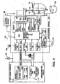
- FIG. 2 is a simplified block diagram of the pressure sensing lead 12 and the IMD 100 in relation to patient's heart 10.
- the lead 12 has first and second lead conductors 14 and 16 extending from the connector 180 to the blood pressure sensor 20 disposed near the distal fixation mechanism 26 and to the distal tip sense electrode 26.
- the blood pressure sensor 20 preferably includes a variable pickoff capacitor and a fixed reference capacitor and signal modulating circuit described in detail in the above-incorporated, commonly assigned, '434 and '752 patents that develops both blood pressure and temperature time-modulated intervals that are decoded as blood pressure and temperature signal values in demodulator 150.
- the proximal end of lead 12 is formed as a conventional bipolar, in-line pacing lead connector and is coupled to the monitor connector 180 which is formed as a conventional bipolar in-line pacemaker pulse generator connector block assembly.
- the circuitry of IMD 100 is powered by battery 108 and generally comprises a microcomputer 114 coupled through data communication bus 130 with an input/output circuit 112 that is coupled to the activity sensor 106, the telemetry antenna 134, the lead conductors 14, 16, and a crystal 110.
- the input/output circuit 112 includes the digital controller/timer circuit 132 and the associated components including the crystal oscillator 138, power-on-reset (POR) circuit 148, Vref/BIAS circuit 140, ADC/MUX circuit 142, RF transmitter/receiver circuit 136, optional activity circuit 152 and pressure signal demodulator 150.
- Crystal oscillator circuit 138 and crystal 110 provide the basic timing clock for the digital controller/timer circuit 132.
- Vref/BIAS circuit 140 generates stable voltage reference Vref and current levels from battery 108 for the circuits within the digital controller/timer circuit 132, and the other identified circuits including microcomputer 114 and demodulator 150.
- Power-on-reset circuit 148 responds to initial connection of the circuitry to the battery 108 for defining an initial operating condition and also resets the operating condition in response to detection of a low battery voltage condition.
- Analog-to-digital converter (ADC) and multiplexor circuit 142 digitizes analog signals Vprs and Vtemp received by digital controller/timer circuit 132 from demodulator 150 for storage by microcomputer 114.
- ADC analog-to-digital converter
- multiplexor circuit 142 digitizes analog signals Vprs and Vtemp received by digital controller/timer circuit 132 from demodulator 150 for storage by microcomputer 114.
- ADC/MUX circuit 142 multiplexes data signals transmitted out through RF transmitter/receiver circuit 136 during telemetry.
- Voltage reference and bias circuit 140, ADC/MUX circuit 142, POR circuit 148, crystal oscillator circuit 138 and optional activity circuit 152 may correspond to any of those presently used in currently marketed cardiac pacemaker IPGs.
- the digital controller/timer circuit 132 includes a set of timers and associated logic circuits connected with the microcomputer 114 through the data communications bus 130.
- Microcomputer 114 contains an on-board chip including microprocessor 120, associated system clock 122, and on-board RAM and ROM chips 124 and 126, respectively.
- microcomputer 114 includes an off-board circuit 118 including separate RAM/ROM chip 128 to provide additional memory capacity.
- Microprocessor 120 is interrupt driven, operating in a reduced power consumption mode normally, and awakened in response to defined interrupt events, which may include the periodic timing out of data sampling intervals for storage of monitored data, the transfer of triggering and data signals on the bus 130 and the receipt of programming signals.
- a real-time clock and calendar function may also be included to correlate stored data, particularly the indices ⁇ and/or ⁇ , to time and date.
- Microcomputer 114 controls the operating functions of digital controller/timer 132, specifying which timing intervals are employed, and controlling the duration of the various timing intervals, via the bus 130.
- the specific current operating modes and interval values are programmable.
- the programmed-in parameter values and operating modes are received through the antenna 134, demodulated in the RF transmitter/receiver circuit 136 and stored in RAM/ROM chip 128.
- Data transmission to and from the external programmer 300 of FIG. 1 is accomplished by means of the telemetry antenna 134 and the associated RF transmitter and receiver 136, which serves both to demodulate received DT transmissions and to UT transmit data to the external programmer 300.
- a number of power, timing and control signals described in greater detail in the above-incorporated, commonly assigned, '434 and '752 patents are supplied by the digital controller/timer circuit 132 to the demodulator 150 to initiate and power the operation of the blood pressure sensor 20 and selectively read out the pressure and temperature signals Vprs and Vtemp.
- An active lead conductor 16 is attached through the connector block terminals to input and output terminals of demodulator 150 that supplies a voltage VREG at the output terminal.
- a passive lead conductor 14 is coupled through to the VDD supply terminal of the demodulator 150.
- the voltage signals Vprs and Vtemp developed from intervals between current pulses received at the input terminal, are provided by demodulator 150 to the digital controller/timer circuit 132.
- the voltage signals Vprs and Vtemp are digitized in an ADC/MUX circuit 142 and stored temporarily in RAM/ROM chip 128 in a manner well known in the art.
- the IMD 100 functions as an implantable physiologic signal sensor, specifically for monitoring and storing digitized blood pressure and temperature data derived from the absolute pressure and temperature sensor 20.
- the patient activity and EGM data can also be stored.
- the EGM of the heart is sensed between the active distal tip electrode 26 and the indifferent electrode formed by the hermetically sealed housing or can 178 of IMD 100 by sense amplifier 170 in a conventional unipolar sensing configuration.
- the sense amplifier 170 declares a V-EVENT when the R-wave is sensed, and the V-EVENT is supplied to the digital controller/timer circuit 132 and functions as an interrupt to the microprocessor 120 in a manner well known in the art.
- FIG. 2 also shows the configuration of a therapy delivery device by inclusion of the therapy delivery system block 40 shown in broken lines.
- the particular therapy delivery system 40 may include one or more of the systems described above, e.g., a single or dual chamber pacing system of the type disclosed in the above-referenced '623 patent, for example.
- the digital controller and timer circuit 132 includes a pressure signal processor of the type disclosed in the above-referenced '040 patent and a real time clock that are employed to derive the peak positive pressure P b , the peak positive derivative pressure dP/dt PP , and the peak negative derivative pressure dP/dt NP from the sampled and digitized V prs signals of each pressure beat.
- the sample times t b , t a , and the sample time t c are also determined by the pressure signal processor in digital controller and timer circuit 132.
- sample times t a , t b , and t c can be made by reference to a time to at the V-EVENT declared preceding the pressure signal measurements.
- the absolute blood pressure at times t a and t c are also determined as pressures P a and P c , respectively.
- digitized values and sample times are temporarily stored in dedicated storage registers or in RAM in RAM/ROM unit 128.
- the calculations can be made during the heart cycle ending with the next V-EVENT.
- Steps S100 - S104 depict the detection of a normal sinus rhythm (NSR) R-wave resulting in declaration of a V-EVENT in FIG. 2
- steps S106 - S116 depict the processing of the digitized V prs and associated time data in accordance with the present invention.
- the storage of the calculated indices ⁇ and ⁇ in steps S114 and S116 can be facilitated to accommodate available memory by compression of the index values to illustrate trends or by storing only one index determined each day or by storage of a running mean of the calculated indices ⁇ and ⁇ .
- NSR the R-wave is sensed across the ventricular sense vector defined as shown in FIGs.
- the collection and processing of ventricular blood pressure data in steps S106 - S110 and the determination of the indices ⁇ and ⁇ as depicted in steps S114 and S 116 preferably only occur when the heart rate is determined to represent NSR in steps S102 to S104. Moreover, if may be desirable to limit the determination of the indices ⁇ and/or ⁇ of ventricular afterload to NSR events at a heart rate that is lower than defined tachyarrhythmia heart rates as determined in step S102.
- a therapy delivery mode or parameter is optimized in step S 118 if the IMD delivers a therapy.
- the optimization of a therapy mode or parameter involves incrementally adjusting the mode or parameter, repeating steps S100 - S116 one or more times to obtain updated values of the indices ⁇ and ⁇ , determining from the ⁇ and ⁇ values whether the change reduces or increases ventricular afterload, readjusting the mode or parameter in the direction that exhibits improvement, and repeating steps S100 - S116.
- Step S118 may be automatically conducted periodically, e.g., once per day when the patient is presumed to be at rest, or only conducted in the presence of a physician in real time in a telemetry session with the external programmer 300.
- FIGs. 4 - 9 The determination of the indices ⁇ and ⁇ from exemplary blood pressure waves under a variety of conditions is depicted in FIGs. 4 - 9 .
- the exemplary blood pressure waves shown in FIGs. 4 - 9 were plotted from real-time, left or right, as indicated, ventricular pressure measurements obtained from an acutely instrumented, surgically exposed heart of an anesthetized dog.
- the left ventricular pressure (LVP) measurements were obtained by placing a high fidelity micro-manometer (Millar Instruments, Houston TX) in the left ventricle of each heart via a stab wound into the exterior carotid artery.
- the analog pressure signal from the micro-manometer was digitized at a sampling frequency of 250 Hz using a personal computer equipped with an analog to digital converter and specialized data acquisition and processing software (Sonometrics, Version 3.2.2, Montreal, Canada).
- the peak pressure P b and the dP/dt values were digitally calculated from the digitized ventricular pressure data using the data acquisition and processing software.
- a snare was looped and tightened around the proximal descending aorta in order to create an aortic occlusion that increased ventricular afterload by increasing resistance and decreasing arterial compliance.
- temporary pacing was administered to the heart in selected pacing modes from a temporary dual chamber pacemaker pulse generator coupled to temporary atrial and ventricular pacing wires sutured to the right atrial appendage and right ventricular apex, respectively.
- FIGs. 4 and 5 are graphical depictions of the determination of the indices ⁇ and ⁇ in steps S 114 and S 116 from the above-described pressure and time data points derived in steps S106 - S110 at points "a", "b” and "c" during a control pressure wave accompanying a control ventricular contraction and during a pressure wave accompanying a ventricular contraction while the aorta is occluded, respectively.
- FIG. 6 is a graphical depiction of the determination of the indices ⁇ and ⁇ in steps S114 and S116 from the above-described pressure and time data points derived in steps S106 - S110 at points "a", "b" and "c" of a heart that is being paced in a VDD pacing mode having an AV delay set to 100 ms.
- FIG. 7 is a graphical depiction of the determination of the indices ⁇ and ⁇ in steps S 114 and S 116 from the above-described pressure and time data points derived in steps S106 - S110 at points "a", "b" and "c" of a heart that is being paced in a VVI pacing mode.
- asynchronous VVI pacing of the right ventricular apex results in less efficient ventricular contraction, again leading to increased ventricular afterload.
- the pacing mode experiments were conducted on dog hearts that did not necessarily require pacing and so the pacing escape intervals were selected to provide pacing to capture the heart at paced heart rates that exceeded the intrinsic heart rate.
- the examples of FIGs. 6 and 7 suggest that the indices ⁇ and ⁇ are sensitive to pacing modes and pacing parameters.
- the examples of FIGS. 6 and 7 also suggest that the pacing mode that might be established for a patient's heart that is pacemaker dependent could negatively affect ventricular afterload. Therefore, the indices ⁇ and ⁇ could be used in a patient work-up to select the pacing mode and pacing parameters of the selected pacing mode for the patient that minimizes ventricular afterload.
- repeated derivations and comparisons of values of ⁇ and magnitudes of ⁇ can be of value in assessing the effect of the pacing mode on the heart over time.
- chronically implantable pressure sensor bearing leads that are commercially available for implantation are recommended for implantation into the right ventricle or right ventricular outflow tract to make right ventricular pressure measurements as described above in reference to FIGs. 1 - 3 .
- these chronically implantable pressure sensor bearing leads function just as well in the left ventricle although such implantation is not explicitly recommended due to possible clot formation and release into the arterial system.
- the technology is available to measure LVP.
- Right and left ventricular afterload are independent of one another; that is a patient can exhibit high RV afterload symptomatic of pulmonary hypertension or high LV afterload.
- High RV afterload is associated with pulmonary hypertension which can lead to right heart failure, right ventricular dilation, RV hypertrophy, tricuspid valve regurgitation, peripheral edema, atrial and ventricular arrhythmias, hypoxia and death.
- High LV afterload is associated with arterial hypertension, pulmonary edema, mitral valve regurgitation, LV dilation, LV hypertrophy, atrial dilation, atrial arrhythmias, LV failure, ventricular arrhythmias acute ischemia and death.
- FIGs. 8 and 9 pressure waveforms and data shown in FIGs. 8 and 9 were derived in the acute experiments by placing the above-described micro-manometer in the left and right ventricles, respectively, of a dog heart to derive the left ventricular pressure (LVP) pressure and time data points or right ventricular pressure (RVP) pressure and time data points from which the LVP and RVP indices ⁇ and ⁇ were determined.
- LVP left ventricular pressure
- RVP right ventricular pressure
- FIG. 8 the dog heart is acutely paced as described above in the VDD pacing mode having an AV delay of 100 ms.
- the wide difference in the LVP and RVP values of ⁇ and magnitudes of ⁇ signify that, in a healthy dog heart, RV afterload is much lower than LV afterload, as is commonly understood.
- the estimates of the ventricular afterload may be used to quantify the current state of cardiovascular function, to discern changes in the state of cardiovascular function over time, and to select or alter a therapy delivered by an IMD to optimize cardiovascular function of patients experiencing heart failure, hypertension and other clinical pathologies as described above.
- the indices of the ventricular afterload derived from ventricular pressure measurements can be advantageously performed acutely to diagnose patients employing temporarily implanted pressure measurement instruments.
Landscapes
- Health & Medical Sciences (AREA)
- Life Sciences & Earth Sciences (AREA)
- Cardiology (AREA)
- Heart & Thoracic Surgery (AREA)
- Engineering & Computer Science (AREA)
- General Health & Medical Sciences (AREA)
- Public Health (AREA)
- Biophysics (AREA)
- Biomedical Technology (AREA)
- Physiology (AREA)
- Veterinary Medicine (AREA)
- Animal Behavior & Ethology (AREA)
- Physics & Mathematics (AREA)
- Medical Informatics (AREA)
- Surgery (AREA)
- Molecular Biology (AREA)
- Hematology (AREA)
- Pathology (AREA)
- Nuclear Medicine, Radiotherapy & Molecular Imaging (AREA)
- Vascular Medicine (AREA)
- Radiology & Medical Imaging (AREA)
- Artificial Intelligence (AREA)
- Computer Vision & Pattern Recognition (AREA)
- Psychiatry (AREA)
- Signal Processing (AREA)
- Electrotherapy Devices (AREA)
- Measuring Pulse, Heart Rate, Blood Pressure Or Blood Flow (AREA)
Claims (7)
- Apparat, der einen Index der Ventrikelnachlast ableitet, welcher den Widerstand gegen die Blutaustreibung aus einer Herzkammer während einer Blutaustreibungsphase aufzeigt, umfassend:Mittel zur Erlangung eines Satzes an Ventrikeldruckwerten des Blutdrucks in einer Herzkammer zu Abtastzeiten während der Blutaustreibungsphase der Herzkammer;Mittel zum Bestimmen des Spitzenpositivdruckwerts Pb, des Spitzenpositivableitungsdrucks dP/dtPP und des Spitzennegativableitungsdrucks dP/dtNP aus dem Satz an Ventrikeldruckwerten;Mittel zum Bestimmen der Abtastzeit tb des Spitzenpositivdrucks, der Abtastzeit ta des Spitzenpositivableitungsdrucks dP/dtPP und der Abtastzeit tc des Spitzennegativableitungsdrucks dP/dtNP aus den Abtastzeiten, die dem Satz an Ventrikeldruckwerten zugehörig sind; undMittel zum Berechnen eines Index α des relativen Zeitpunkts des Spitzenpositivdrucks Pb in der Blutaustreibungsphase gemäß der Formel α = (tb - ta)/(tc - ta), wobei der Schweregrad der Ventikelnachlast proportional zu dem Wert von Index α im Bereich zwischen 0 und 1 ist.
- Apparatur nach Anspruch 1, des Weiteren umfassend:Mittel zum Bestimmen des abnehmenden Drucks Pc, der dem Spitzennegativableitungsdruck dP/dtNP aus dem Satz an Ventrikeldruckwerten zugehörig ist; undMittel zum Berechnen eines Index β des Anstiegs des frühen Austreibungsdrucks in der Blutaustreibungsphase gemäß der Formel β = (Pc - Pb)/(tc - tb), wobei der Schweregrad der Kammernachlast proportional zu der Größe von Index β ist.
- Apparat zum Ableiten eines Index der Ventrikelnachlast, der den Widerstand gegen die Blutaustreibung aus einer Herzkammer während einer Blutaustreibungsphase aufzeigt, umfassend:Mittel zum Erlangen eines Satzes an Ventrikeldruckwerten des Blutdrucks in einer Herzkammer zu Abtastzeiten während der Blutaustreibungsphase der Herzkammer;Mittel zum Bestimmen des Spitzenpositivdruckwerts Pb, des Spitzenpositivableitungsdruckwerts dP/dtPP und des Spitzennegativableitungsdrucks dP/dtNP aus dem Satz an Ventrikeldruckwerten;Mittel zum Bestimmen des Spitzenpositivdruckwerts Pb, des Spitzennegativableitungsdrucks dP/dtNP und des abnehmenden Drucks Pc, der dem Spitzennegativableitungsdruck dP/dtNP aus dem Satz an Ventrikeldruckwerten zugehörig ist;Mittel zum Bestimmen der Abtastzeit tb des Spitzenpositivdrucks und der Abtastzeit tc des Spitzennegativableitungsdrucks dP/dtNP aus den Abtastzeiten, die dem Satz an Ventrikeldruckwerten zugehörig sind; undMittel zum Berechnen eines Index β des Anstiegs des frühen Austreibungsdrucks in der Blutaustreibungsphase gemäß der Formel β = (Pc - Pb)/(tc - tb), wobei der Schweregrad der Kammernachlast proportional zu der Größe von Index β ist.
- Apparatur nach Anspruch 1, umfassend einen Datensicherungsspeicher zum Sichern des errechneten Index α.
- Apparatur nach Anspruch 2 oder 3, umfassend ein Datensicherungsmittel zum Sichern des errechneten Index β.
- Implantierbares Herzüberwachungsgerät, das dafür geeignet ist, in den Körper eines Patienten implantiert zu werden, umfassend einen Druckfühler, der an einen Drucksignalverarbeitungsschaltkreis und einen Speicher zur Datensicherung gekoppelt ist, umfassend einen Apparat gemäß einem der vorangehenden Ansprüche.
- Implantierbares Herzüberwachungsgerät, das dafür geeignet ist, in den Körper eines Patienten implantiert zu werden, zum Verabreichen einer Therapie in Übereinstimmung mit einstellbaren Betriebsmodi und Parametern der Therapieverabreichung, umfassend einen Druckfühler, der an einen Drucksignalverarbeitungsschaltkreis und ein Therapieverabreichungsmittel zum Verabreichen einer Therapie gekoppelt ist, umfassend einen Apparat gemäß einem der Ansprüche 1 bis 5.
Applications Claiming Priority (3)
| Application Number | Priority Date | Filing Date | Title |
|---|---|---|---|
| US10/376,064 US6887207B2 (en) | 2003-02-26 | 2003-02-26 | Methods and apparatus for estimation of ventricular afterload based on ventricular pressure measurements |
| US376064 | 2003-02-26 | ||
| PCT/US2004/004624 WO2004075745A1 (en) | 2003-02-26 | 2004-02-17 | Methods and apparatus for estimation of ventricular afterload based on ventricular pressure measurements |
Publications (2)
| Publication Number | Publication Date |
|---|---|
| EP1599133A1 EP1599133A1 (de) | 2005-11-30 |
| EP1599133B1 true EP1599133B1 (de) | 2009-03-25 |
Family
ID=32869077
Family Applications (1)
| Application Number | Title | Priority Date | Filing Date |
|---|---|---|---|
| EP04711883A Expired - Lifetime EP1599133B1 (de) | 2003-02-26 | 2004-02-17 | Verfahren und gerät zur abschätzung der ventrikelnachbelastung basiert auf ventrickeldruckmessungen |
Country Status (6)
| Country | Link |
|---|---|
| US (1) | US6887207B2 (de) |
| EP (1) | EP1599133B1 (de) |
| JP (1) | JP4611972B2 (de) |
| CA (1) | CA2516948A1 (de) |
| DE (1) | DE602004020193D1 (de) |
| WO (1) | WO2004075745A1 (de) |
Families Citing this family (60)
| Publication number | Priority date | Publication date | Assignee | Title |
|---|---|---|---|---|
| US20050154370A1 (en) * | 1999-10-29 | 2005-07-14 | Medtronic, Inc. | Methods and systems for providing therapies into the pericardial space |
| US6994676B2 (en) * | 2003-04-30 | 2006-02-07 | Medtronic, Inc | Method and apparatus for assessing ventricular contractile status |
| US7232435B2 (en) * | 2004-02-06 | 2007-06-19 | Medtronic, Inc. | Delivery of a sympatholytic cardiovascular agent to the central nervous system to counter heart failure and pathologies associated with heart failure |
| US20050222640A1 (en) * | 2004-02-12 | 2005-10-06 | Schwartz Robert S | Heart muscle stimulator and pacing method for treating hypertension |
| US8086315B2 (en) | 2004-02-12 | 2011-12-27 | Asap Medical, Inc. | Cardiac stimulation apparatus and method for the control of hypertension |
| US8755885B2 (en) * | 2004-10-13 | 2014-06-17 | Medtronic, Inc. | Software configurable medical device platform and associated methods |
| US20060116590A1 (en) * | 2004-11-30 | 2006-06-01 | Pacesetter, Inc. | Endocardial pressure differential sensing systems and methods |
| US7708693B2 (en) * | 2005-01-27 | 2010-05-04 | Medtronic, Inc. | System and method for detecting artifactual hemodynamic waveform data |
| US20060167361A1 (en) | 2005-01-27 | 2006-07-27 | Bennett Tommy D | Method and apparatus for continuous pulse contour cardiac output |
| US7367951B2 (en) | 2005-01-27 | 2008-05-06 | Medtronic, Inc. | System and method for detecting cardiovascular health conditions using hemodynamic pressure waveforms |
| US7927284B2 (en) * | 2005-09-16 | 2011-04-19 | Cardiac Pacemakers, Inc. | Quantifying hemodynamic response to drug therapy using implantable sensor |
| US7792581B2 (en) * | 2006-02-28 | 2010-09-07 | Medtronic, Inc. | Method and apparatus for treating diastolic heart failure |
| US8360983B2 (en) | 2006-06-22 | 2013-01-29 | Cardiac Pacemakers, Inc. | Apnea type determining apparatus and method |
| US7678058B2 (en) * | 2006-06-22 | 2010-03-16 | Cardiac Pacemakers, Inc. | Apnea type determining apparatus and method |
| US8271080B2 (en) * | 2007-05-23 | 2012-09-18 | Cardiac Pacemakers, Inc. | Decongestive therapy titration for heart failure patients using implantable sensor |
| US8340750B2 (en) * | 2007-07-19 | 2012-12-25 | Medtronic, Inc. | Mechanical function marker channel for cardiac monitoring and therapy control |
| US8211028B2 (en) | 2008-04-30 | 2012-07-03 | Medtronic, Inc. | System and method of determining arterial blood pressure and ventricular fill parameters from ventricular blood pressure waveform data |
| US8145293B2 (en) * | 2008-06-16 | 2012-03-27 | Siemens Medical Solutions Usa, Inc. | Adaptive medical image acquisition system and method |
| US8200466B2 (en) | 2008-07-21 | 2012-06-12 | The Board Of Trustees Of The Leland Stanford Junior University | Method for tuning patient-specific cardiovascular simulations |
| US8328728B2 (en) * | 2008-08-22 | 2012-12-11 | Pacesetter, Inc. | Implantable hemodynamic monitor and methods for use therewith |
| WO2010027652A1 (en) * | 2008-08-26 | 2010-03-11 | Cardiac Pacemakers, Inc. | Cardiac output estimation using pulmonary artery pressure |
| US9405886B2 (en) | 2009-03-17 | 2016-08-02 | The Board Of Trustees Of The Leland Stanford Junior University | Method for determining cardiovascular information |
| RU2413458C2 (ru) * | 2009-05-04 | 2011-03-10 | Государственное образовательное учреждение высшего профессионального образования "Юго-Западный государственный университет" (ЮЗГУ) | Способ оценки сердечно-сосудистого риска у больных с артериальной гипертензией |
| US8784310B2 (en) * | 2009-07-02 | 2014-07-22 | Cardiac Pacemakers, Inc. | Vascular pressure sensor with electrocardiogram electrodes |
| US9301699B2 (en) | 2009-09-18 | 2016-04-05 | St. Jude Medical Coordination Center Bvba | Device for acquiring physiological variables measured in a body |
| US8315812B2 (en) | 2010-08-12 | 2012-11-20 | Heartflow, Inc. | Method and system for patient-specific modeling of blood flow |
| US9008769B2 (en) | 2012-12-21 | 2015-04-14 | Backbeat Medical, Inc. | Methods and systems for lowering blood pressure through reduction of ventricle filling |
| JP6353208B2 (ja) * | 2013-10-18 | 2018-07-04 | 学校法人自治医科大学 | 生体情報管理装置、生体情報管理方法および生体情報管理プログラム |
| US9370662B2 (en) | 2013-12-19 | 2016-06-21 | Backbeat Medical, Inc. | Methods and systems for controlling blood pressure by controlling atrial pressure |
| US10342982B2 (en) | 2015-09-11 | 2019-07-09 | Backbeat Medical, Inc. | Methods and systems for treating cardiac malfunction |
| US10485658B2 (en) | 2016-04-22 | 2019-11-26 | Backbeat Medical, Inc. | Methods and systems for controlling blood pressure |
| DE102016209871A1 (de) | 2016-06-06 | 2017-12-07 | Robert Bosch Gmbh | Stanzvorrichtung und Verfahren zum Stanzen eines Lumens und Implantieren einer Implantateinrichtung |
| DE102018201030B4 (de) | 2018-01-24 | 2025-10-16 | Kardion Gmbh | Magnetkuppelelement mit magnetischer Lagerungsfunktion |
| US11517740B2 (en) * | 2018-03-15 | 2022-12-06 | Tc1 Llc | Methods for controlling a left ventricular assist device |
| DE102018206725A1 (de) | 2018-05-02 | 2019-11-07 | Kardion Gmbh | Empfangseinheit, Sendeeinheit, Energieübertragungssystem und Verfahren zur drahtlosen Energieübertragung |
| DE102018206750A1 (de) | 2018-05-02 | 2019-11-07 | Kardion Gmbh | Vorrichtung zur induktiven Energieübertragung in einen menschlichen Körper und deren Verwendung |
| DE102018206754A1 (de) | 2018-05-02 | 2019-11-07 | Kardion Gmbh | Verfahren und Vorrichtung zur Bestimmung der Temperatur an einer Oberfläche sowie Verwendung des Verfahrens |
| DE102018206724A1 (de) | 2018-05-02 | 2019-11-07 | Kardion Gmbh | Energieübertragungssystem und Verfahren zur drahtlosen Energieübertragung |
| DE102018206727A1 (de) | 2018-05-02 | 2019-11-07 | Kardion Gmbh | Energieübertragungssystem und Empfangseinheit zur drahtlosen transkutanen Energieübertragung |
| DE102018206731A1 (de) | 2018-05-02 | 2019-11-07 | Kardion Gmbh | Vorrichtung zur induktiven Energieübertragung in einen menschlichen Körper und Verwendung der Vorrichtung |
| DE102018208538A1 (de) | 2018-05-30 | 2019-12-05 | Kardion Gmbh | Intravasale Blutpumpe und Verfahren zur Herstellung von elektrischen Leiterbahnen |
| DE102018208555A1 (de) | 2018-05-30 | 2019-12-05 | Kardion Gmbh | Vorrichtung zum Verankern eines Herzunterstützungssystems in einem Blutgefäß, Verfahren zum Betreiben und Herstellverfahren zum Herstellen einer Vorrichtung und Herzunterstützungssystem |
| DE102018208899A1 (de) | 2018-06-06 | 2019-12-12 | Kardion Gmbh | Verfahren zum Ermitteln der Schallgeschwindigkeit in einem Fluid im Bereich eines implantierten, vaskulären Unterstützungssystems |
| DE102018208862A1 (de) | 2018-06-06 | 2019-12-12 | Kardion Gmbh | Implantierbares, vaskuläres Unterstützungssystem |
| DE102018208936A1 (de) | 2018-06-06 | 2019-12-12 | Kardion Gmbh | Bestimmvorrichtung und Verfahren zum Bestimmen einer Viskosität eines Fluids |
| DE102018208879A1 (de) | 2018-06-06 | 2020-01-30 | Kardion Gmbh | Verfahren zur Bestimmung eines Fluid-Gesamtvolumenstroms im Bereich eines implantierten, vaskuläres Unterstützungssystems |
| DE102018208933A1 (de) | 2018-06-06 | 2019-12-12 | Kardion Gmbh | Verfahren zur Bestimmung einer Strömungsgeschwindigkeit eines durch ein implantiertes, vaskuläres Unterstützungssystem strömenden Fluids |
| DE102018208931A1 (de) | 2018-06-06 | 2019-12-12 | Kardion Gmbh | Vorrichtung zum Bestimmen eines Herzzeitvolumens für ein Herzunterstützungssystem, Herzunterstützungssystem und Verfahren zum Bestimmen eines Herzzeitvolumens |
| DE102018208870A1 (de) | 2018-06-06 | 2019-12-12 | Kardion Gmbh | Verfahren zur Bestimmung eines Fluid-Volumenstroms durch ein implantiertes, vaskuläres Unterstützungssystem |
| DE102018208929A1 (de) | 2018-06-06 | 2019-12-12 | Kardion Gmbh | Verfahren zur Bestimmung einer Strömungsgeschwindigkeit eines durch ein implantiertes, vaskuläres Unterstützungssystem strömenden Fluids |
| DE102018208913A1 (de) | 2018-06-06 | 2019-12-12 | Kardion Gmbh | Verfahren zum Betreiben eines implantierten, ventrikulären Unterstützungssystems |
| DE102018208892A1 (de) | 2018-06-06 | 2019-12-12 | Kardion Gmbh | Sensorkopfvorrichtung für ein minimalinvasives Herzunterstützungssystem und Verfahren zum Herstellen einer Sensorkopfvorrichtung für ein Herzunterstützungssystem |
| DE102018208945A1 (de) | 2018-06-06 | 2019-12-12 | Kardion Gmbh | Analysevorrichtung und Verfahren zum Analysieren einer Viskosität eines Fluids |
| DE102018210076A1 (de) | 2018-06-21 | 2019-12-24 | Kardion Gmbh | Verfahren und Vorrichtung zum Erkennen eines Verschleißzustands eines Herzunterstützungssystems, Verfahren und Vorrichtung zum Betreiben eines Herzunterstützungssystems und Herzunterstützungssystem |
| DE102018213350A1 (de) | 2018-08-08 | 2020-02-13 | Kardion Gmbh | Vorrichtung und Verfahren zur Überwachung eines Gesundheitszustands des Patienten |
| WO2020132460A1 (en) | 2018-12-21 | 2020-06-25 | Medtronic, Inc. | Acute heart failure monitoring and treatment |
| US11116456B2 (en) | 2019-06-27 | 2021-09-14 | Medtronic, Inc. | Sensing for heart failure management |
| US11699551B2 (en) | 2020-11-05 | 2023-07-11 | Kardion Gmbh | Device for inductive energy transmission in a human body and use of the device |
| US12502524B2 (en) | 2021-12-03 | 2025-12-23 | Kardion Gmbh | Cardiac pump with optical fiber for laser doppler |
| JP7424423B1 (ja) * | 2022-07-20 | 2024-01-30 | コニカミノルタ株式会社 | 動態画像解析装置、プログラム及び動態画像解析方法 |
Family Cites Families (26)
| Publication number | Priority date | Publication date | Assignee | Title |
|---|---|---|---|---|
| US4429701A (en) * | 1981-09-22 | 1984-02-07 | Daniel Goor | Method and apparatus for measuring the systemic vascular resistance of a cardiovascular system |
| US4664125A (en) * | 1984-05-10 | 1987-05-12 | Pinto John G | Flow-occluding method for the diagnosis of heart conditions |
| CA2082015C (en) * | 1991-11-04 | 2001-03-20 | Rodney W. Salo | Implantable cardiac function monitor and stimulator for diagnosis and therapy delivery |
| US5368040A (en) * | 1993-08-02 | 1994-11-29 | Medtronic, Inc. | Apparatus and method for determining a plurality of hemodynamic variables from a single, chroniclaly implanted absolute pressure sensor |
| IL107540A0 (en) * | 1993-11-08 | 1994-02-27 | Nevo Erez | Method and apparatus for assessing cardiovascular performance |
| US5564434A (en) * | 1995-02-27 | 1996-10-15 | Medtronic, Inc. | Implantable capacitive absolute pressure and temperature sensor |
| US5743267A (en) * | 1995-10-19 | 1998-04-28 | Telecom Medical, Inc. | System and method to monitor the heart of a patient |
| US5758652A (en) * | 1995-10-19 | 1998-06-02 | Nikolic; Serjan D. | System and method to measure the condition of a patients heart |
| US5626623A (en) * | 1996-04-30 | 1997-05-06 | Medtronic, Inc. | Method and apparatus for optimizing pacemaker AV delay |
| US5819735A (en) * | 1996-08-15 | 1998-10-13 | Mansfield; Elizabeth A. | Device and method for monitoring dietary intake of calories and nutrients |
| AU5427098A (en) * | 1996-11-04 | 1998-05-29 | Johns Hopkins University, The | Assessing cardiac contractility and cardiovascular interaction |
| US5904708A (en) * | 1998-03-19 | 1999-05-18 | Medtronic, Inc. | System and method for deriving relative physiologic signals |
| JP3062474B2 (ja) * | 1998-04-22 | 2000-07-10 | 充 高島 | 循環器系総合評価装置 |
| US6045513A (en) * | 1998-05-13 | 2000-04-04 | Medtronic, Inc. | Implantable medical device for tracking patient functional status |
| US6104949A (en) * | 1998-09-09 | 2000-08-15 | Vitatron Medical, B.V. | Medical device |
| US6155267A (en) * | 1998-12-31 | 2000-12-05 | Medtronic, Inc. | Implantable medical device monitoring method and system regarding same |
| US6309350B1 (en) * | 1999-05-03 | 2001-10-30 | Tricardia, L.L.C. | Pressure/temperature/monitor device for heart implantation |
| JP2000333911A (ja) * | 1999-05-25 | 2000-12-05 | Nippon Colin Co Ltd | 心機能監視装置 |
| US6440078B1 (en) * | 1999-07-23 | 2002-08-27 | Roberto Curiel | Method and system of determining cardiac contractility |
| JP3480703B2 (ja) * | 1999-10-07 | 2003-12-22 | 株式会社志成データム | 血行動態測定装置、血行動態測定方法および記録媒体 |
| US6275707B1 (en) * | 1999-10-08 | 2001-08-14 | Motorola, Inc. | Method and apparatus for assigning location estimates from a first transceiver to a second transceiver |
| US7252842B2 (en) * | 2000-12-21 | 2007-08-07 | Alrise Biosystems Gmbh | Induced phase transition method for the production of microparticles containing hydrophilic active agents |
| US6438408B1 (en) * | 2000-12-28 | 2002-08-20 | Medtronic, Inc. | Implantable medical device for monitoring congestive heart failure |
| JP4674978B2 (ja) * | 2001-02-01 | 2011-04-20 | Cyberdyne株式会社 | 心機能評価装置 |
| JP4680411B2 (ja) * | 2001-04-26 | 2011-05-11 | 株式会社 タウザー研究所 | 動脈血圧測定方法および動脈血圧測定装置 |
| JP3731071B2 (ja) * | 2001-07-02 | 2006-01-05 | 関西ティー・エル・オー株式会社 | 血行動態測定方法 |
-
2003
- 2003-02-26 US US10/376,064 patent/US6887207B2/en not_active Expired - Lifetime
-
2004
- 2004-02-17 JP JP2006503631A patent/JP4611972B2/ja not_active Expired - Fee Related
- 2004-02-17 WO PCT/US2004/004624 patent/WO2004075745A1/en not_active Ceased
- 2004-02-17 EP EP04711883A patent/EP1599133B1/de not_active Expired - Lifetime
- 2004-02-17 DE DE602004020193T patent/DE602004020193D1/de not_active Expired - Lifetime
- 2004-02-17 CA CA002516948A patent/CA2516948A1/en not_active Abandoned
Also Published As
| Publication number | Publication date |
|---|---|
| US6887207B2 (en) | 2005-05-03 |
| WO2004075745A1 (en) | 2004-09-10 |
| US20040167410A1 (en) | 2004-08-26 |
| EP1599133A1 (de) | 2005-11-30 |
| JP4611972B2 (ja) | 2011-01-12 |
| DE602004020193D1 (de) | 2009-05-07 |
| JP2006519055A (ja) | 2006-08-24 |
| CA2516948A1 (en) | 2004-09-10 |
Similar Documents
| Publication | Publication Date | Title |
|---|---|---|
| US6887207B2 (en) | Methods and apparatus for estimation of ventricular afterload based on ventricular pressure measurements | |
| US6371922B1 (en) | Method for measuring baroreflex sensitivity and therapy optimization in heart failure patients | |
| US9049995B2 (en) | System and method for detecting pulmonary congestion based on stroke volume using an implantable medical device | |
| US6438408B1 (en) | Implantable medical device for monitoring congestive heart failure | |
| US6738667B2 (en) | Implantable medical device for treating cardiac mechanical dysfunction by electrical stimulation | |
| US8103345B2 (en) | Cardiac pacing using adjustable atrio-ventricular delays | |
| EP1341439B1 (de) | Apparat zur messung des mittleren blutdruckes in der lungenarterie von der herzkammer aus mit einem mobilen überwachungsgerät | |
| US6915157B2 (en) | Implantable medical device for assessing heart failure state from Mechanical Pulsus Alternans | |
| EP0902708B1 (de) | Vorrichtung zur optimierung der av-verzögerung in einem herzschrittmacher | |
| US6959214B2 (en) | Implantable medical device for measuring mechanical heart function | |
| EP1079893B1 (de) | Herzreizung unter verwendung von einstellbaren atrio-ventrikulären verzögerungsintervallen | |
| US8594790B2 (en) | System and method for monitoring a ventricular pressure index to predict worsening heart failure | |
| US10478629B2 (en) | Leadless cardiac pacemaker for generating cardiac pressure volume loop | |
| US20030199779A1 (en) | Estimation of stroke volume cardiac output using an intracardiac pressure sensor | |
| US20080288013A1 (en) | Pulmonary pressure monitoring | |
| EP2805673B1 (de) | System zur Bewertung der diastolischen Funktion auf Basis von kardiogener Impedanz mithilfe einer implantierbaren medizinischen Vorrichtung | |
| US7794404B1 (en) | System and method for estimating cardiac pressure using parameters derived from impedance signals detected by an implantable medical device | |
| WO2006118713A1 (en) | Measurement of coronary sinus parameters to optimize left ventricular performance | |
| US7192399B2 (en) | System and method for monitoring myocardial performance using sensed ventricular pressures | |
| US20180021585A1 (en) | Leadless medical system for quantifying ventricle to ventricle dyssynchrony |
Legal Events
| Date | Code | Title | Description |
|---|---|---|---|
| PUAI | Public reference made under article 153(3) epc to a published international application that has entered the european phase |
Free format text: ORIGINAL CODE: 0009012 |
|
| 17P | Request for examination filed |
Effective date: 20050926 |
|
| AK | Designated contracting states |
Kind code of ref document: A1 Designated state(s): AT BE BG CH CY CZ DE DK EE ES FI FR GB GR HU IE IT LI LU MC NL PT RO SE SI SK TR |
|
| AX | Request for extension of the european patent |
Extension state: AL LT LV MK |
|
| DAX | Request for extension of the european patent (deleted) | ||
| RBV | Designated contracting states (corrected) |
Designated state(s): CH DE FR LI NL SE |
|
| RIN1 | Information on inventor provided before grant (corrected) |
Inventor name: HETTRICK, DOUGLAS, A. |
|
| GRAP | Despatch of communication of intention to grant a patent |
Free format text: ORIGINAL CODE: EPIDOSNIGR1 |
|
| GRAS | Grant fee paid |
Free format text: ORIGINAL CODE: EPIDOSNIGR3 |
|
| GRAA | (expected) grant |
Free format text: ORIGINAL CODE: 0009210 |
|
| AK | Designated contracting states |
Kind code of ref document: B1 Designated state(s): CH DE FR LI NL SE |
|
| REG | Reference to a national code |
Ref country code: CH Ref legal event code: EP |
|
| REF | Corresponds to: |
Ref document number: 602004020193 Country of ref document: DE Date of ref document: 20090507 Kind code of ref document: P |
|
| PG25 | Lapsed in a contracting state [announced via postgrant information from national office to epo] |
Ref country code: SE Free format text: LAPSE BECAUSE OF FAILURE TO SUBMIT A TRANSLATION OF THE DESCRIPTION OR TO PAY THE FEE WITHIN THE PRESCRIBED TIME-LIMIT Effective date: 20090625 |
|
| NLV1 | Nl: lapsed or annulled due to failure to fulfill the requirements of art. 29p and 29m of the patents act | ||
| PG25 | Lapsed in a contracting state [announced via postgrant information from national office to epo] |
Ref country code: NL Free format text: LAPSE BECAUSE OF FAILURE TO SUBMIT A TRANSLATION OF THE DESCRIPTION OR TO PAY THE FEE WITHIN THE PRESCRIBED TIME-LIMIT Effective date: 20090325 |
|
| PLBE | No opposition filed within time limit |
Free format text: ORIGINAL CODE: 0009261 |
|
| STAA | Information on the status of an ep patent application or granted ep patent |
Free format text: STATUS: NO OPPOSITION FILED WITHIN TIME LIMIT |
|
| 26N | No opposition filed |
Effective date: 20091229 |
|
| REG | Reference to a national code |
Ref country code: CH Ref legal event code: PL |
|
| PG25 | Lapsed in a contracting state [announced via postgrant information from national office to epo] |
Ref country code: LI Free format text: LAPSE BECAUSE OF NON-PAYMENT OF DUE FEES Effective date: 20100228 Ref country code: CH Free format text: LAPSE BECAUSE OF NON-PAYMENT OF DUE FEES Effective date: 20100228 |
|
| REG | Reference to a national code |
Ref country code: FR Ref legal event code: PLFP Year of fee payment: 13 |
|
| REG | Reference to a national code |
Ref country code: FR Ref legal event code: PLFP Year of fee payment: 14 |
|
| REG | Reference to a national code |
Ref country code: FR Ref legal event code: PLFP Year of fee payment: 15 |
|
| PGFP | Annual fee paid to national office [announced via postgrant information from national office to epo] |
Ref country code: DE Payment date: 20190122 Year of fee payment: 16 |
|
| REG | Reference to a national code |
Ref country code: DE Ref legal event code: R119 Ref document number: 602004020193 Country of ref document: DE |
|
| PG25 | Lapsed in a contracting state [announced via postgrant information from national office to epo] |
Ref country code: DE Free format text: LAPSE BECAUSE OF NON-PAYMENT OF DUE FEES Effective date: 20200901 |
|
| PGFP | Annual fee paid to national office [announced via postgrant information from national office to epo] |
Ref country code: FR Payment date: 20210120 Year of fee payment: 18 |
|
| PG25 | Lapsed in a contracting state [announced via postgrant information from national office to epo] |
Ref country code: FR Free format text: LAPSE BECAUSE OF NON-PAYMENT OF DUE FEES Effective date: 20220228 |