EP1598783A1 - Bildrekonstruktionsverfahren und Roentgen-Computertomograph - Google Patents
Bildrekonstruktionsverfahren und Roentgen-Computertomograph Download PDFInfo
- Publication number
- EP1598783A1 EP1598783A1 EP05252910A EP05252910A EP1598783A1 EP 1598783 A1 EP1598783 A1 EP 1598783A1 EP 05252910 A EP05252910 A EP 05252910A EP 05252910 A EP05252910 A EP 05252910A EP 1598783 A1 EP1598783 A1 EP 1598783A1
- Authority
- EP
- European Patent Office
- Prior art keywords
- image
- ray
- cad
- dedicated
- image reconstruction
- Prior art date
- Legal status (The legal status is an assumption and is not a legal conclusion. Google has not performed a legal analysis and makes no representation as to the accuracy of the status listed.)
- Withdrawn
Links
Images



Classifications
-
- G—PHYSICS
- G06—COMPUTING OR CALCULATING; COUNTING
- G06T—IMAGE DATA PROCESSING OR GENERATION, IN GENERAL
- G06T5/00—Image enhancement or restoration
- G06T5/70—Denoising; Smoothing
-
- G—PHYSICS
- G06—COMPUTING OR CALCULATING; COUNTING
- G06T—IMAGE DATA PROCESSING OR GENERATION, IN GENERAL
- G06T12/00—Tomographic reconstruction from projections
- G06T12/10—Image preprocessing, e.g. calibration, positioning of sources or scatter correction
-
- G—PHYSICS
- G06—COMPUTING OR CALCULATING; COUNTING
- G06T—IMAGE DATA PROCESSING OR GENERATION, IN GENERAL
- G06T12/00—Tomographic reconstruction from projections
- G06T12/30—Image post-processing, e.g. metal artefact correction
-
- G—PHYSICS
- G06—COMPUTING OR CALCULATING; COUNTING
- G06T—IMAGE DATA PROCESSING OR GENERATION, IN GENERAL
- G06T5/00—Image enhancement or restoration
- G06T5/50—Image enhancement or restoration using two or more images, e.g. averaging or subtraction
-
- G—PHYSICS
- G06—COMPUTING OR CALCULATING; COUNTING
- G06T—IMAGE DATA PROCESSING OR GENERATION, IN GENERAL
- G06T2207/00—Indexing scheme for image analysis or image enhancement
- G06T2207/10—Image acquisition modality
- G06T2207/10072—Tomographic images
- G06T2207/10081—Computed x-ray tomography [CT]
-
- G—PHYSICS
- G06—COMPUTING OR CALCULATING; COUNTING
- G06T—IMAGE DATA PROCESSING OR GENERATION, IN GENERAL
- G06T2207/00—Indexing scheme for image analysis or image enhancement
- G06T2207/30—Subject of image; Context of image processing
- G06T2207/30004—Biomedical image processing
-
- Y—GENERAL TAGGING OF NEW TECHNOLOGICAL DEVELOPMENTS; GENERAL TAGGING OF CROSS-SECTIONAL TECHNOLOGIES SPANNING OVER SEVERAL SECTIONS OF THE IPC; TECHNICAL SUBJECTS COVERED BY FORMER USPC CROSS-REFERENCE ART COLLECTIONS [XRACs] AND DIGESTS
- Y10—TECHNICAL SUBJECTS COVERED BY FORMER USPC
- Y10S—TECHNICAL SUBJECTS COVERED BY FORMER USPC CROSS-REFERENCE ART COLLECTIONS [XRACs] AND DIGESTS
- Y10S378/00—X-ray or gamma ray systems or devices
- Y10S378/901—Computer tomography program or processor
Definitions
- the present invention relates to an image reconstruction method and an X-ray computed tomography (CT) system. More particularly, the present invention relates to a method of reconstructing an image on the basis of a plurality of views of projection data items provided by X-rays having passed through a subject, and an X-ray CT system performing the image reconstruction.
- CT computed tomography
- X-ray CT systems acquire a plurality of views-of projection data items from a subject, and reconstruct an image on the basis of the projection data items.
- processes such as pre-processing, reconstruction, and post-processing devised on the assumption of visual assessment of an image are employed. Therefore, even when computer-aided detection (CAD) is performed based on a reconstructed image, an image reconstructed on the assumption of the visual assessment is employed (refer to, for example, Japanese Unexamined Patent Application Publication No. 2004-070562 (pp.4-5, Fig. 1)
- images for use in visual assessment have a high-frequency component thereof enhanced so that an image will appeal to naked eyes.
- Algorithms adapted to CAD include an algorithm that employs a differential filter. There is therefore a possibility that the differential filter function defined for CAD and a reconstruction function defined for visual assessment may enhance a noise to make recognition of an image, which is performed during CAD, unstable, and degrade a lesion image detection rate.
- the present invention seeks to provide a method of reconstructing an image that will be recognized stably during CAD, and an X-ray CT system performing the image reconstruction.
- the image reconstruction comprises a reconstruction function dedicated to the computer-sided detection (CAD) mode so that a reconstructed image suitable for CAD can be produced.
- CAD computer-sided detection
- the image reconstruction comprises preprocessing that includes noise removal for removing a noise from projection data, such as, streaky artifact removal dedicated to the computer-aided detection (CAD) mode.
- noise removal for removing a noise from projection data
- CAD computer-aided detection
- a streaky artifact and other artifacts in a tomographic image can be effectively removed in order to improve image quality. This results in a reconstructed image suitable for CAD.
- the image reconstruction comprises post-processing that includes a noise removal filter dedicated to the computer-aided detection (CAD) so that a noise can be effectively removed in order to produce a reconstructed image suitable for CAD.
- CAD computer-aided detection
- the image reconstruction comprises a user interface dedicated to the computer-aided detection (CAD) mode so that image reconstruction dedicated to the CAD mode can be achieved properly.
- CAD computer-aided detection
- the user interface permits selection of a reconstruction function dedicated to the CAD mode so that the reconstruction function dedicated to the CAD mode can be selected properly.
- the user interface permits selection of preprocessing that includes noise removal for removing a noise from projection data, such as, streaky artifact removal dedicated to a computer-aided detection (CAD) mode.
- noise removal for removing a noise from projection data
- CAD computer-aided detection
- the user interface permits the post-processing that includes a noise removal filter dedicated to a computer-aided detection (CAD) mode so that the post-processing dedicated to the CAD mode can be selected properly.
- CAD computer-aided detection
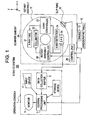
- an X-ray CT system 100 comprises an operator console 1, a radiographic table 10, and a scanner gantry 20.
- the operator console 1 comprises: an input device 2 that receives an operator's entry; a central processing unit 3 that executes image reconstruction or the like; a data collection buffer 5 in which projection data acquired by the scanner gantry 20 is collected; a monitor 6 on which a CT image reconstructed based on projection data is displayed; and a storage device 7 in which programs, data, reconstructed images are stored.
- the central processing unit 3 is an example of an image reconstruction means employed in the present invention.
- the input device 2 and monitor 6 constitute an example of an interface included in the present invention.
- the radiographic table 10 includes a cradle 12 that is carried in or out of a bore of the scanner gantry 20 with a subject laid down thereon.
- the cradle 12 is raised or lowered, or moved rectilinearly by a motor incorporated in the radiographic table 10.
- the scanner gantry 20 comprises: an X-ray tube 21, an X-ray controller 22; a collimator 23; an X-ray detector 24; a data acquisition system (DAS) 25; a rotary assembly controller 26 for rotating the X-ray tube 21 and others about the body axis of a subject; and a control unit 29 for transferring control signals or the like to or from the operator console 1 or radiographic table 10.
- the X-ray tube 21 is an example of an X-ray generation means included in the present invention.
- the X-ray detector 24 is an example of an X-ray detection means included in the present invention.
- the configuration of the X-ray CT system has been outlined so far.
- projection data is acquired, for example, as described below.
- a subject is carried into the bore of a rotary assembly 15 included in the scanner gantry 20.
- the position of the subject in a z-axis (body-axis) direction is fixed, and an X-ray beam radiated from the X-ray tube 21 is irradiated to the subject (projection of X-rays).
- the X-ray detector 24 detects transmitted X-rays.
- the detection of transmitted X-rays is performed in the directions of N views (where N equals, for example, 1000) while the X-ray tube 21 and X-ray detector 24 are being rotated about the subject (that is, while a projection angle (view angle) is being varied).
- N equals, for example, 1000
- the data acquisition system (DAS) 25 analog-to-digital converts transmitted X-rays that are detected, and then transfers projection data to the operator console 1 via the data collection buffer 5. This sequence of actions shall be referred to as one scan.
- a scan position is shifted by a predetermined length in the z-axis direction, and the next scan is performed.
- This scanning technique is called a conventional scanning (or axial scanning) technique.
- a technique in which while the radiographic table 10 is being moved at a predetermined speed synchronously with a change in a projection angle and the scan position is being shifted (while the X-ray tube 21 and X-ray detector 24 are helically rotating about a subject), projection data is acquired is the so-called helical scanning technique.
- the present invention can be adapted to both the conventional scanning and helical scanning techniques.
- tilt scanning is achieved.
- the tilt scanning can be combined with either of the conventional scanning and helical scanning techniques.
- the operator console 1 stores projection data, which is transferred from the scanner gantry 20, in a fixed disk HDD that is part of the storage device 7 connected to the central processing unit 3.
- the projection data is convoluted to a predetermined reconstruction function, and then subjected to back projection in order to reconstruct a tomographic image.
- a tomographic image can be reconstructed in real time using projection data sequentially transferred from the scanner gantry 20 during scanning, and the latest tomographic image is displayed on the monitor 6 all the time.
- projection data may be read from the fixed disk or hard disk in order to reconstruct an image.
- Image reconstruction and CAD will be described below.
- detection of a lesion image included in CAD employs processing relatively susceptible to a noise, such as, contour tracking or local change sampling.
- image reconstruction included in X-ray CT generally employs a reconstruction function, which enhances a harmonic frequency component, because the image reconstruction is applied on the assumption of visual assessment of an image. The reconstruction function is adjusted in line with human vision.
- CAD based on automatic image recognition sensitively reacts to a delicate change in a density or a spatial change occurring in units of a pixel, but is insensitive to a local and moderate change. If image reconstruction dedicated to CAD is available, CAD would be more effectively performed.
- a low-frequency component is reflected on reconstruction of an image in order to remove a noise, which occurs during binary-coding, from the delineation.
- a high-frequency component may be reflected on image reconstruction.
- a noise in an image occurring during detection of a candidate for a lesion image within CAD is suppressed and a detection rate of CAD is improved.
- a reconstruction function is devised so that it will interact with a differential filter included for CAD but will not excessively enhance a noise.
- a reconstruction function defined to enhance a low-frequency component more greatly than the one defined for visual assessment is used for image reconstruction in order to remove a noise in a delineation occurring during binary-coding.
- a high-frequency component is reflected on image reconstruction.
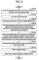
- Fig. 2 is the explanatory diagram describing the flow of processing to be performed in the operator console 1 included in the present embodiment.
- a CAD streaky artifact minimization mode a reconstruction function, and a post-processing noise filter are selected.
- the section is achieved by an operator (user).
- the section is achieved by utilizing user interfaces shown in Fig. 3.
- the user interfaces are displayed on the monitor 6, and the operator uses the input device 2 for selection.
- the user interface concerning the streaky artifact minimization mode presents three items AAR1, AAR2, and CAD.
- the items AAR1 and AAR2 permit selection of menus concerning visual image assessment.
- the item CAD permits selection of a menu concerning CAD.
- the CAD menu specifies streaky artifact minimization that is more effective than that specified in the visual image assessment menus AAR1 and AAR2.
- the item CAD is selected.
- the user interface concerning a reconstruction function presents five items Lung Field, Head, Bone, Abdomen, and CAD.
- the items Lung Field to Abdomen permit selection of menus concerning visual image assessment.
- the item CAD permits selection of a menu concerning CAD.
- the CAD menu specifies low-frequency enhancement that is more effective than that specified in the visual image assessment menus AAR1 and AAR2. Herein, the item CAD is selected.
- the user interface concerning a post-processing noise filter presents three items Noise Filter 1, Noise Filter 2, and CAD.
- the items Noise Filter 1 and Noise Filter 2 permit selection of menus concerning visual image assessment.
- the item CAD permits selection of a menu concerning CAD.
- the CAD menu specifies noise removal that is more effective than that specified in the visual image assessment menus Noise Filter 1 and Noise Filter 2.
- the item CAD is selected.
- a region that is an object of CAD is scanned.
- the lung field is scanned.
- step S11 projection data is pre-processed. Namely, CAD streaky artifact minimization is executed. The pre-processing is performed according to the contents of the CAD menu selected at step S0.
- the pre-processed projection data is convoluted to a reconstruction function defined for reflecting a low-frequency component on image reconstruction and to a reconstruction function defined for reflecting a high-frequency component thereon.
- the convolution is performed according to the contents of the CAD menu selected at step S0.
- step S3 the projection data items resulting from the convolutions to the two reconstruction functions are back-projected, and the resultant tomographic images are weighted according to whether CT numbers exceed or fall below a threshold, and thus moderately differentiated from each other. Consequently, the tomographic images are produced using the reconstruction functions for CAD.
- the tomographic images are post-processed, that is, a CAD noise filter is applied to them.
- the post-processing is achieved according to the contents of the CAD menu selected at step S0.
- step S5 the tomographic images are displayed. Namely, the image of the lung field like the one shown in Fig. 4 is displayed.
- CAD is performed in order to sample and display a candidate for a lesion image.
- Fig. 5 describes the flow of processing, which is part of CAD, for sampling and displaying a candidate for a lesion image.
- a tomographic image is binary-coded based on a predetermined threshold in order to delineate the lung field. Namely, as shown in Fig. 6, a logical filter for delineating the lung field is used to delineate the lung field.
- Step S62 a lesion image located on the delineation of the lung field is sampled from the tomographic image of the lung field. Namely, as shown in Fig. 7, for example, five delineation tracking dots having a space, which corresponds to a pixel, between adjoining ones are moved along the delineation of the lung field. The positional relationships among the five dots are checked to see if a candidate for a lesion image is present.
- an intrapulmonary region image contained in the tomographic image of the lung field is binary-coded based on a predetermined threshold in order to sample a candidate-for-lesion image within the intrapulmonary region image.
- serial numbers are assigned to respective candidates for a lesion.
- a parameter indicating a feature of each candidate for a lesion image is calculated.
- step S66 the parameter indicating a feature of each candidate for a lesion image is checked to see if the candidate is a lesion image.
- step S67 the presumable lesion image is displayed.
- Fig. 8 is a flowchart describing the steps S64, S65, S66, and S67 in details.
- the flowchart describes lesion image detection to be performed in the operator console 1.
- a plurality of tomographic images Si acquired by scanning a subject h at consecutive different slicing positions is transferred.
- the tomographic images shown in Fig. 9 are binary-coded as they are, all of an inlet-like vascular image, a capillary image, and a candidate-for-lesion image are sampled through binary-coding. Therefore, during the processing described below, first, the inlet-like vascular image is padded with a certain value and the capillary image and the candidate-for-lesion image are sampled.
- a tomographic image is binary-coded so that CT numbers permitting sampling of a whole lung image (for example, -200 or less) will be represented with 1s and the other CT numbers will be represented with 0s. Consequently, as shown in Fig. 10, lung images L and a background (air) A are represented with 1 s and the other images are represented with 0s. In Fig. 10, the images represented with 1s are hatched. Inlet-like vascular images La in Fig. 10 express thick blood vessels leading to the respective lungs L.
- a three-dimensional or two-dimensional logical filter is applied to the images represented with 1 s in order to contract or expand N pixels.
- a microscopic image observed as a noise is removed (for example, N equals 5, but the N value is varied depending on the size of one pixel).
- the images represented with 1 s are three-dimensionally or two-dimensionally labeled in order to segment them.
- the segment estimated as the background (air) is removed. Consequently, only the lung images are the images represented with 1 s.
- Fig. 11 shows the lung images.
- a three-dimensional or two-dimensional logical filter is applied to the images represented with 1 s in order to enlarge and contract M pixels.
- the inlet-like images La that are unnecessary images are padded with 1 s (for example, M equals 10, but the M value is varied depending on the size of one pixel). Consequently, as shown in Fig. 12, the inlet-like images La disappear from the lung images L.
- the AND of pixels constituting the tomographic images Si is calculated in order to cut out the images padded with 1 s at step S644.
- the cutouts are binary-coded so that CT numbers permitting sampling of the capillary image (for example, a range from -500 to +1000 because CT numbers calculated from a contrast-enhanced vascular image range from 100 to 200, and CT numbers calculated from a vascular image whose contrast is not enhanced data items representing vessels whose visualization range from 40 to 50) will be represented with 1 s and the other CT numbers will be represented with 0s. Consequently, as shown in Fig. 13, a candidate-for-vessel images Va contained in the lung images L are represented with 1 s and the other portions of the lung images are represented with 0s.
- the candidate-for-vessel images Va contained in the lung images L are three-dimensionally modeled.
- a three-dimensional logical filter is applied to the candidate-of-vessel images Va in the lung images L in order to expand and contract L pixels.
- the candidates for vascular images v1, v2, v3, etc. whose data items are separated from one another are, as shown in Fig. 14, repaired to be linked (for example, L ranges from 1 to 3, but the L value is varied depending on the size of one pixel).
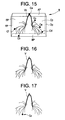
- the candidate-for-vessel images Va are, as shown in Fig. 15, three-dimensionally labeled in order to segment the candidate-for-vessel images Va into candidates for vascular images Vb.
- step S648 as shown in Fig. 15, the volume of a circumscribed rectangular parallelepiped B that is defined with xmin ⁇ x ⁇ xmax, ymin ⁇ y ⁇ ymax, and zmin ⁇ z ⁇ zmax and that encloses all the voxels of the candidates for vascular images Vb is calculated. Thereafter, the candidate for a vascular image Vb having the largest volume is identified as a three-dimensional vascular image V. The other labeled three-dimensional images are removed as noises.
- Fig. 16 shows the three-dimensional vascular image V. In Fig. 15, the candidates for vascular images Vb are in contact with the top AP of the circumscribed rectangular parallelepiped, the bottom BP thereof, and the sides CP to FP thereof at points Ca to Cf.
- a three-dimensional logical filter is applied to the blood vessel image V in order to contract P pixels. Consequently, the peripheral vascular images are deleted.
- P denotes a value calculated by adding one or two pixels to the thickness of a peripheral vascular image (for example, P ranges from 4 to 5, but the P value is varied depending on the size of one pixel).
- an isolated candidate-for-lesion image Ca remains at the position of the periphery of the vascular image V.
- the sphericity ⁇ of the candidate-for-lesion image Ca is calculated.
- three-dimensional data representing the candidate-for-lesion image Ca is produced based on the candidate-for-lesion image Ca and the plurality of successive tomographic images Si, and CT numbers calculated based on the three-dimensional data is averaged.
- a peripheral-lesion image is detected.
- a lesion image C is substantially spherical.
- the vascular image V is substantially columnar.
- the candidate-for-lesion image Ca is verified to be a lesion image. Otherwise, the candidate-for-lesion image Ca is not verified to be a lesion image.
- the sphericity ⁇ is determined as described below.
- a lesion image detecting method at least the sphericity is adopted as a parameter indicating a feature of a three-dimensional image.
- a superficial area S and a volume is V
- the probability that the candidate-for-lesion image is a lesion image gets higher.
- a three-dimensional logical filter is applied to the vascular image V, which is left intact despite contraction performed after step S649, in order to contract Q pixels.
- the major vascular image is deleted.
- Q denotes a value calculated by subtracting P from the sum of the thickness of the major vascular image and one or two pixels (for example, Q ranges from 7 to 8 but the Q value is varied depending on the size of one pixel).
- an isolated candidate-for-lesion image Cb remains at the position of the major vascular image V.
- the sphericity ⁇ of the candidate-for-lesion image Cb is calculated.
- three-dimensional data representing the candidate-for-lesion image Cb is produced based on the candidate-for-lesion image Cb and the plurality of successive tomographic images Si. CT numbers calculated from the three-dimensional data is averaged. Based on the sphericity ⁇ of the candidate-for-lesion image Cb and the average CT number, a major vascular lesion image is detected.
- the processing ending at step S645 is two-dimensional processing
- the processing starting at step S646 is three-dimensional processing.
- the whole processing starting at step S642 may be three-dimensional processing.
- three-dimensional data is constructed based on the plurality of tomographic images Si.
- a threshold for use in detecting a lesion image is determined with a blood vessel image divided in terms of the thickness into a peripheral vascular image and a major vascular image.
- the blood vessel image may be divided in terms of thickness into three portions, and a lesion image may be detected in each of the three portions.
- the step S646 may be omitted.
- a program to be installed in a computer in order to implement the processing in accordance with the present invention in the computer, and a storage medium in which the program is stored are also implementations of the present invention. Namely, the scope of the present invention encompasses the program for implementing the processing in accordance with the present invention and the storage medium in which the program is stored so that the program will be readable by a computer.
- the storage medium for use in providing the program may be, for example, a flexible disk, an optical disk (CD-ROM, CD-R, CD-RW, DVD, etc.), a magneto-optical disk, a magnetic tape, and a memory card.
- Methods for providing the program include a mode in which the program in accordance with the present invention is transferred as a file.
Landscapes
- Physics & Mathematics (AREA)
- General Physics & Mathematics (AREA)
- Engineering & Computer Science (AREA)
- Theoretical Computer Science (AREA)
- Apparatus For Radiation Diagnosis (AREA)
- Image Processing (AREA)
Applications Claiming Priority (2)
| Application Number | Priority Date | Filing Date | Title |
|---|---|---|---|
| JP2004141795 | 2004-05-12 | ||
| JP2004141795A JP4260060B2 (ja) | 2004-05-12 | 2004-05-12 | X線ct装置および画像再構成装置 |
Publications (1)
| Publication Number | Publication Date |
|---|---|
| EP1598783A1 true EP1598783A1 (de) | 2005-11-23 |
Family
ID=34941257
Family Applications (1)
| Application Number | Title | Priority Date | Filing Date |
|---|---|---|---|
| EP05252910A Withdrawn EP1598783A1 (de) | 2004-05-12 | 2005-05-11 | Bildrekonstruktionsverfahren und Roentgen-Computertomograph |
Country Status (4)
| Country | Link |
|---|---|
| US (1) | US7082181B2 (de) |
| EP (1) | EP1598783A1 (de) |
| JP (1) | JP4260060B2 (de) |
| CN (1) | CN100393280C (de) |
Families Citing this family (18)
| Publication number | Priority date | Publication date | Assignee | Title |
|---|---|---|---|---|
| JP2007000406A (ja) * | 2005-06-24 | 2007-01-11 | Ge Medical Systems Global Technology Co Llc | X線ct撮影方法およびx線ct装置 |
| JP2007044207A (ja) * | 2005-08-09 | 2007-02-22 | Ge Medical Systems Global Technology Co Llc | 放射線ct撮影方法およびx線ct装置 |
| JP4509903B2 (ja) * | 2005-09-27 | 2010-07-21 | ジーイー・メディカル・システムズ・グローバル・テクノロジー・カンパニー・エルエルシー | X線ct装置 |
| GB2435976A (en) * | 2006-03-09 | 2007-09-12 | Medicsight Plc | Digital medical image processing for CAD detection of abnormalities |
| JP5196751B2 (ja) * | 2006-09-13 | 2013-05-15 | 株式会社東芝 | コンピュータ支援診断装置 |
| CN100435736C (zh) * | 2006-12-13 | 2008-11-26 | 林井副 | 基于多层螺旋ct的人体索条状组织同层显示成像方法 |
| CN101868809B (zh) * | 2007-09-10 | 2013-01-02 | 皇家飞利浦电子股份有限公司 | 具有计算机辅助检测和/或诊断的图像处理 |
| US8442309B2 (en) * | 2009-06-04 | 2013-05-14 | Honda Motor Co., Ltd. | Semantic scene segmentation using random multinomial logit (RML) |
| KR101135205B1 (ko) * | 2010-05-25 | 2012-04-16 | 인하대학교 산학협력단 | 흉부 씨티 영상 내 병변 자동 검출을 위한 폐 혈관 추출 방법 |
| KR20150016032A (ko) | 2013-08-02 | 2015-02-11 | 삼성전자주식회사 | 영상 복원 모드 선택이 가능한 영상 복원 방법 및 그 장치 |
| KR102205906B1 (ko) * | 2013-12-09 | 2021-01-22 | 삼성전자주식회사 | 이미지 내 오브젝트 윤곽선의 수정 방법 및 시스템 |
| WO2017165191A2 (en) * | 2016-03-23 | 2017-09-28 | The Procter & Gamble Company | Imaging method for determining stray fibers |
| CN106651753B (zh) * | 2016-09-28 | 2020-03-17 | 东软医疗系统股份有限公司 | 提高ct图像显示效果的方法及装置 |
| US11364004B2 (en) | 2018-02-08 | 2022-06-21 | Covidien Lp | System and method for pose estimation of an imaging device and for determining the location of a medical device with respect to a target |
| WO2019220871A1 (ja) | 2018-05-16 | 2019-11-21 | パナソニック株式会社 | 胸部x線画像の異常表示制御方法、異常表示制御プログラム、異常表示制御装置、及びサーバ装置 |
| JP7143118B2 (ja) * | 2018-05-23 | 2022-09-28 | 浜松ホトニクス株式会社 | 大腰筋領域画定装置および大腰筋領域画定方法 |
| JP7125312B2 (ja) * | 2018-09-07 | 2022-08-24 | 富士フイルムヘルスケア株式会社 | 磁気共鳴撮像装置、画像処理装置、及び、画像処理方法 |
| CN109615602B (zh) * | 2018-12-11 | 2021-05-28 | 艾瑞迈迪科技石家庄有限公司 | 一种x光视角图像的生成方法、存储介质以及终端设备 |
Citations (4)
| Publication number | Priority date | Publication date | Assignee | Title |
|---|---|---|---|---|
| US6125193A (en) * | 1998-06-01 | 2000-09-26 | Kabushiki Kaisha Toshiba | Method and system for high absorption object artifacts reduction and superposition |
| US20030035507A1 (en) * | 2001-08-17 | 2003-02-20 | Li-Yueh Hsu | Computer-aided diagnosis system for thoracic computer tomography images |
| US20030095697A1 (en) * | 2000-11-22 | 2003-05-22 | Wood Susan A. | Graphical user interface for display of anatomical information |
| WO2004017263A2 (en) * | 2002-08-14 | 2004-02-26 | Koninklijke Philips Electronics N.V. | Method and apparatus for generating improved computer tomography images of natural tissues |
Family Cites Families (10)
| Publication number | Priority date | Publication date | Assignee | Title |
|---|---|---|---|---|
| US6553356B1 (en) | 1999-12-23 | 2003-04-22 | University Of Pittsburgh - Of The Commonwealth System Of Higher Education | Multi-view computer-assisted diagnosis |
| WO2001078005A2 (en) * | 2000-04-11 | 2001-10-18 | Cornell Research Foundation, Inc. | System and method for three-dimensional image rendering and analysis |
| US6707878B2 (en) | 2002-04-15 | 2004-03-16 | General Electric Company | Generalized filtered back-projection reconstruction in digital tomosynthesis |
| US6724856B2 (en) | 2002-04-15 | 2004-04-20 | General Electric Company | Reprojection and backprojection methods and algorithms for implementation thereof |
| JP2004070562A (ja) | 2002-08-05 | 2004-03-04 | Hitachi Medical Corp | 医用画像処理クライアント/認証サーバ・システム及び認証サーバ |
| US7006591B2 (en) * | 2002-09-09 | 2006-02-28 | Kabushiki Kaisha Toshiba | Computed tomography apparatus and program |
| US6748044B2 (en) | 2002-09-13 | 2004-06-08 | Ge Medical Systems Global Technology Company, Llc | Computer assisted analysis of tomographic mammography data |
| US7433507B2 (en) * | 2003-07-03 | 2008-10-07 | Ge Medical Systems Global Technology Co. | Imaging chain for digital tomosynthesis on a flat panel detector |
| US7492855B2 (en) | 2003-08-07 | 2009-02-17 | General Electric Company | System and method for detecting an object |
| US7447341B2 (en) * | 2003-11-26 | 2008-11-04 | Ge Medical Systems Global Technology Company, Llc | Methods and systems for computer aided targeting |
-
2004
- 2004-05-12 JP JP2004141795A patent/JP4260060B2/ja not_active Expired - Fee Related
-
2005
- 2005-05-09 US US11/124,946 patent/US7082181B2/en not_active Expired - Fee Related
- 2005-05-11 EP EP05252910A patent/EP1598783A1/de not_active Withdrawn
- 2005-05-12 CN CNB2005100714712A patent/CN100393280C/zh not_active Expired - Fee Related
Patent Citations (4)
| Publication number | Priority date | Publication date | Assignee | Title |
|---|---|---|---|---|
| US6125193A (en) * | 1998-06-01 | 2000-09-26 | Kabushiki Kaisha Toshiba | Method and system for high absorption object artifacts reduction and superposition |
| US20030095697A1 (en) * | 2000-11-22 | 2003-05-22 | Wood Susan A. | Graphical user interface for display of anatomical information |
| US20030035507A1 (en) * | 2001-08-17 | 2003-02-20 | Li-Yueh Hsu | Computer-aided diagnosis system for thoracic computer tomography images |
| WO2004017263A2 (en) * | 2002-08-14 | 2004-02-26 | Koninklijke Philips Electronics N.V. | Method and apparatus for generating improved computer tomography images of natural tissues |
Also Published As
| Publication number | Publication date |
|---|---|
| US7082181B2 (en) | 2006-07-25 |
| CN100393280C (zh) | 2008-06-11 |
| JP2005323628A (ja) | 2005-11-24 |
| US20050254617A1 (en) | 2005-11-17 |
| CN1695559A (zh) | 2005-11-16 |
| JP4260060B2 (ja) | 2009-04-30 |
Similar Documents
| Publication | Publication Date | Title |
|---|---|---|
| EP1598783A1 (de) | Bildrekonstruktionsverfahren und Roentgen-Computertomograph | |
| US5647360A (en) | Digital subtraction angiography for 3D diagnostic imaging | |
| EP1741062B1 (de) | Conus-strahl-ct-vorrichtung mit abgeschnittenen projektionen und einem zuvor erfassten 3d-ct-bild | |
| EP2126842B1 (de) | Bewegungsermittlung System zur Bestimmung der Bewegung eines sich periodisch bewegenden Objekts. | |
| US7545903B2 (en) | Reconstruction of an image of a moving object from volumetric data | |
| US6810102B2 (en) | Methods and apparatus for truncation compensation | |
| JP4728627B2 (ja) | Ct血管造影法における構造を領域分割する方法及び装置 | |
| JP4576032B2 (ja) | 2回パス式コーン・ビーム画像再構成の方法及び装置 | |
| US20060029268A1 (en) | Image displaying apparatus, image displaying method, computer readable medium and computer program product | |
| US6574500B2 (en) | Imaging methods and apparatus particularly useful for two and three-dimensional angiography | |
| JPH09253079A (ja) | X線断層撮影装置 | |
| JP2007268273A (ja) | 骨または他のカルシウム含有物質と軟部組織内の造影剤との自動差別化方法および装置 | |
| JP2001504734A (ja) | 斜位画像面を有するctシステム | |
| US7680313B2 (en) | Method and apparatus for post-processing of a 3D image data record, in particular for virtual colonography | |
| CN112120722B (zh) | X射线断层合成装置、图像处理装置以及记录介质 | |
| JP2002336238A (ja) | 円錐ビーム投影データから3次元画像を再構成する方法及び装置 | |
| JP2013085955A (ja) | 連続マルチスケール再構成において詳細画像を補うx線コンピュータ断層撮像装置(x線ct装置)、医用画像処理装置及び医用画像処理方法 | |
| KR101783964B1 (ko) | 단층 촬영 장치 및 그에 따른 단층 영상 복원 방법 | |
| CN102376084A (zh) | 使用各向异性噪声模型对ct图像的迭代图像滤波 | |
| EP2619729B1 (de) | Quantifizierung einer eigenschaft eines lumens einer rohrförmigen struktur | |
| US7376254B2 (en) | Method for surface-contouring of a three-dimensional image | |
| JPH09187452A (ja) | 螺旋走査において収集される投影走査データから発生される像データにおけるアーティファクトを減少させる方法及び装置 | |
| US6647084B1 (en) | Method and apparatus for filtering projection data of a helical scan | |
| Snyder et al. | Increasing the effective resolution of thermal infrared images | |
| Bruder et al. | Cardiac spiral imaging in computed tomography without ECG using complementary projections for motion detection |
Legal Events
| Date | Code | Title | Description |
|---|---|---|---|
| PUAI | Public reference made under article 153(3) epc to a published international application that has entered the european phase |
Free format text: ORIGINAL CODE: 0009012 |
|
| AK | Designated contracting states |
Kind code of ref document: A1 Designated state(s): AT BE BG CH CY CZ DE DK EE ES FI FR GB GR HU IE IS IT LI LT LU MC NL PL PT RO SE SI SK TR |
|
| AX | Request for extension of the european patent |
Extension state: AL BA HR LV MK YU |
|
| 17P | Request for examination filed |
Effective date: 20060523 |
|
| AKX | Designation fees paid |
Designated state(s): DE FR NL |
|
| 17Q | First examination report despatched |
Effective date: 20100408 |
|
| STAA | Information on the status of an ep patent application or granted ep patent |
Free format text: STATUS: THE APPLICATION IS DEEMED TO BE WITHDRAWN |
|
| 18D | Application deemed to be withdrawn |
Effective date: 20100819 |