EP1598577A2 - Positionswahleinrichtung für ein automatisches Getriebe - Google Patents
Positionswahleinrichtung für ein automatisches Getriebe Download PDFInfo
- Publication number
- EP1598577A2 EP1598577A2 EP05291076A EP05291076A EP1598577A2 EP 1598577 A2 EP1598577 A2 EP 1598577A2 EP 05291076 A EP05291076 A EP 05291076A EP 05291076 A EP05291076 A EP 05291076A EP 1598577 A2 EP1598577 A2 EP 1598577A2
- Authority
- EP
- European Patent Office
- Prior art keywords
- operating
- signal
- select
- position variation
- lever
- Prior art date
- Legal status (The legal status is an assumption and is not a legal conclusion. Google has not performed a legal analysis and makes no representation as to the accuracy of the status listed.)
- Withdrawn
Links
Images


Classifications
-
- F—MECHANICAL ENGINEERING; LIGHTING; HEATING; WEAPONS; BLASTING
- F16—ENGINEERING ELEMENTS AND UNITS; GENERAL MEASURES FOR PRODUCING AND MAINTAINING EFFECTIVE FUNCTIONING OF MACHINES OR INSTALLATIONS; THERMAL INSULATION IN GENERAL
- F16H—GEARING
- F16H61/00—Control functions within control units of change-speed- or reversing-gearings for conveying rotary motion ; Control of exclusively fluid gearing, friction gearing, gearings with endless flexible members or other particular types of gearing
- F16H61/26—Generation or transmission of movements for final actuating mechanisms
- F16H61/28—Generation or transmission of movements for final actuating mechanisms with at least one movement of the final actuating mechanism being caused by a non-mechanical force, e.g. power-assisted
- F16H61/32—Electric motors , actuators or related electrical control means therefor
- F16H2061/323—Electric motors , actuators or related electrical control means therefor for power assistance, i.e. servos with follow up action
-
- F—MECHANICAL ENGINEERING; LIGHTING; HEATING; WEAPONS; BLASTING
- F16—ENGINEERING ELEMENTS AND UNITS; GENERAL MEASURES FOR PRODUCING AND MAINTAINING EFFECTIVE FUNCTIONING OF MACHINES OR INSTALLATIONS; THERMAL INSULATION IN GENERAL
- F16H—GEARING
- F16H61/00—Control functions within control units of change-speed- or reversing-gearings for conveying rotary motion ; Control of exclusively fluid gearing, friction gearing, gearings with endless flexible members or other particular types of gearing
- F16H61/26—Generation or transmission of movements for final actuating mechanisms
- F16H61/28—Generation or transmission of movements for final actuating mechanisms with at least one movement of the final actuating mechanism being caused by a non-mechanical force, e.g. power-assisted
- F16H61/32—Electric motors , actuators or related electrical control means therefor
- F16H2061/326—Actuators for range selection, i.e. actuators for controlling the range selector or the manual range valve in the transmission
-
- Y—GENERAL TAGGING OF NEW TECHNOLOGICAL DEVELOPMENTS; GENERAL TAGGING OF CROSS-SECTIONAL TECHNOLOGIES SPANNING OVER SEVERAL SECTIONS OF THE IPC; TECHNICAL SUBJECTS COVERED BY FORMER USPC CROSS-REFERENCE ART COLLECTIONS [XRACs] AND DIGESTS
- Y10—TECHNICAL SUBJECTS COVERED BY FORMER USPC
- Y10T—TECHNICAL SUBJECTS COVERED BY FORMER US CLASSIFICATION
- Y10T74/00—Machine element or mechanism
- Y10T74/20—Control lever and linkage systems
- Y10T74/20012—Multiple controlled elements
- Y10T74/20018—Transmission control
Definitions
- the present invention relates to an operating position select device for an automatic transmission by which a driver can select by operating a select lever one of select mode positions corresponding to a plurality of operation modes of the automatic transmission.
- This select device includes a select lever unit disposed near a driver's seat in a passenger compartment and a mode shift unit mounted on an automatic transmission.
- the select lever unit has a select lever manually operated by a driver and is connected with the mode shift unit by a connecting mechanism, such as a control cable, or a connecting linkage, which transmits an operating force applied on the select lever by the driver to the mode shift unit to shift operation modes of the automatic transmission.
- the conventional art has a problem that the select lever unit needs a long select lever in order to operate it without a large operating force of the driver, which reduces design freedom concerning an installation location of the select lever unit and/or a layout of a passenger compartment.
- This select device is, what is called, a shift-by-wire type one. It has a select lever manually operated by a driver, a select position detector for detecting a position of the select lever, a mode shift unit mounted on an automatic transmission for shifting its operation modes, an electric motor for driving a mode shift unit, and a control unit for controlling the electric motor based on an output signal from the detector.
- This select device is suitable for shortening a length of the select lever and expanding design freedom for its installation location and/or layout of a passenger compartment, while the select device lacks a mechanical connection between the select lever and the mode shift unit. This lack of the mechanical connection results in a problem that the mode shift unit can not be sifted despite of operating the select lever in case of electrical failure such that an electric wire is broken, or the select position detector or the control unit fails.
- an object of the present invention to provide an operating position select device for an automatic transmission which overcomes the foregoing drawbacks and can expand design freedom concerning layout of a passenger compartment and/or an installation location of a select lever unit, and drive a mode shift unit despite of electric failure of the operating position select device.
- an operating position select device for an automatic transmission whose operation modes are shiftable, the operating position select device comprising: a select lever unit having a select lever that is operated by a driver between a plurality of select positions corresponding to the operation modes; an operating position sensor that detects an operating position of the select lever and outputs an operating position signal; a mode shift unit mounted on the automatic transmission to shift operation modes of the automatic transmission; a shift position sensor that detects a shift position of the mode shift unit and outputs a shift position signal; a mechanically connecting means that mechanically connects the select lever and the mode shift unit with each other; an assist actuator that is arranged between the select lever and the mode shift unit and supplies assist force to the select lever; and a control unit that controls the assist actuator, wherein the mechanically connecting means has a torque transmittable adjuster at an intermediate part thereof, the torque transmittable adjuster having play for changing a length thereof and an elastic member disposed into the play so as to transmit force through the torque transmittable adjuster.
- FIG. 1 of the drawing there is shown an automatic transmission 19 and an operating position select device 100 to control the transmission 19.
- the automatic transmission 19 is a conventional multi-speed transmission with a plurality of planetary gear sets, not shown, and is operatable among a plurality of operation modes, for example, a parking mode, a reverse drive mode, a neutral mode, a forward drive mode, and a forward low gear drive mode.
- the automatic transmission 19 is provided with the operating position select device 100, which shifts the operation modes to a desired operation mode by manually selecting a select lever 2 of the select device 100.
- the operating position select device 100 includes a select lever unit 1 manually operated by a driver, an mode shift unit 300 mounted on the automatic transmission 19, a first, second, and third control cables 8a, 8b, and 18 connecting the select lever 2 to the mode shift unit 300, an operating angle sensor 51 for detecting an operating angle of the select lever 2, an assist actuator 9 for assisting operating force inputted from the select lever 2 by the driver, a shift position sensor 200 for detecting a shift angle of , and a control unit 22 for controlling the assist actuator 9.
- the select lever unit 1 is arranged, for example, at a center console 3 beside a driver's seat and has the select lever 2 operated by the driver, a bracket 5 fixed to a vehicle body, a supporting shaft 5a fixed on the bracket 5 so as to swingably support the select lever 2, and a knob 4 mounted on the top of the select lever 2 so as to be held by a hand of the driver.
- the select lever 2 is set to be approximately 100 mm in length in this embodiment, which is shorter by approximately 250 mm than a conventional type select lever.
- the lever 2 is operatable by the driver swingably in a first direction toward a P position as indicated by an arrow BP and in a second direction, opposite to the first direction, toward an L position as indicated by an arrow B L .
- the select lever 2 can be positioned in one of select positions: the P position corresponding to the parking mode of the automatic transmission 19, an R position corresponding to the reverse drive mode, an N position corresponding to the neutral mode, a D position corresponding to the forward drive mode, and the L position corresponding to the forward low geared drive mode.
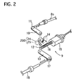
- the assist actuator 9 as shown in FIGS. 1 and 2, includes an electric motor 15 with reduction gears for reducing rotation speed of an output shaft of the motor 15, a worm 16 formed on the outer peripheral surface of the output shaft, and a worm wheel 14 meshing with the worm 16 and integrally united to the coupling shaft 12 for coupling the second and third control cables 8b and 18.
- the worm wheel 14 is provided on its upper surface with an electric terminal 24 contacting to a carbon resistor 25, indicated by a dashed line in FIG. 2, that is printed on a substrate fixed to a case of the assist actuator 9.
- the electric terminal 24 and the carbon resistor 25 constitute the shift angle sensor 200 for detecting a shift angle of a manual plate lever 20 mounted on the automatic transmission 19 to output a shift angle signal to the control unit 22.
- the electric terminal 24 is movable together with and around the coupling shaft 12 to change its position with respect to the carbon resistor 25 that is immobile, so that the shift angle sensor 200 can detect a rotating angle of the coupling shaft 12, substantially corresponding to the shift angle of the manual lever 20, and output the shift angle signal.
- the shift angle in the P position is set to a base angle, and the shift angle sensor 200 detects shift angle with respect to the base angle.
- the shift angle signal is set to increase as the select lever 2 moves toward the L position, in the second direction B L .
- the shift angle sensor 200 acts as a shift position sensor of the present invention, and the shift angle signal corresponds to a shift position signal of the present invention.
- the mode shift unit 300 shifts the operation modes of the automatic transmission 19 according to an operated position of the select lever 2.
- the mode shift unit 300 has the manual plate lever 20 and a detent mechanism 350 for keeping the manual plate lever 20 in a position selected by the select lever 2.
- the manual plate lever 20 is integrally fixed in its intermediate portion with a rotary shaft 26, and connected at its one end portion with the third control cable 18 so as to be rotated on the shaft 26 with respect to a transmission case of the transmission 19 according to a select operation of the select lever 2.
- the rotary shaft 26 is fixed to a detent plate 27 of the detent mechanism 350.
- the detent mechanism 350 includes the detent plate 27 with a cam 270, a detent pin 29 to be pressed onto the cam 270, and a spring plate 28 acting its spring force on the detent pin 29.
- the detent plate 27 is mechanically connected with a valve spool 310 of a manual valve disposed in a control valve unit 400 of the automatic transmission 19 so as to move the spool 300 according to a select position.
- the detent plate 27 is formed on its upper portion with the cam 270 having top portions 27a and bottom portions 27b. Each bottom portion 27b is arranged between the adjacent top portions 27a and corresponds with one of the five operation modes of the automatic transmission 19.
- the cam 270 is pressed by the detent pin 29 that is urged by the spring plate 28.
- the spring plate 28 is mounted at its one end portion on the control valve unit 400 and supports the detent pin 29 at its other end portion.
- the spring plate 28 presses the detent pin 29 onto the cam 270 of the detent plate 27 so that the detent pin 29 is positioned in one of the bottom portions 27b to detain the valve spool 310 of the manual valve in the selected position.
- the detent plate 27 is coupled at its cam side portion with a parking rod 30 having a wedge 30a that can press a parking pawl 31.
- the wedge 30a is movable along the rod 30 and presses the parking pawl 31 by spring force of a coil spring 30b so that the pawl 31 engages with a parking wheel 32 united to an output shaft of the automatic transmission 19 when the select lever 2 is shifted to the P position.
- This engagement of the pawl 31 and the wheel 32 results in locking drive wheels, not shown, for parking a motor vehicle.
- the mode shift unit 300 is mechanically connected with the select lever 2 through the first, second and third control cables 8a, 8b, and 18, and others.
- the first control cable 8a connects at its one end portion with a bottom portion of the select lever 2 through a first joint 7 and at the other end portion with a piston 8c movable in a cylinder 8d connected with an one end portion of the second control cable 8b.
- the second control cable 8b is connected with one end portion of an input lever 10 through a second joint 11.
- the other end portion of the input lever 10 is connected with a top portion of a coupling shaft 12, whose bottom portion is connected with one end portion of an output lever 13.
- the other end portion of the output lever 13 is connected with one end portion of the third control cable 18 through a third joint 17.
- the other end portion of the second control cable 18 is, as shown in FIGS. 1 and 3, connected with the manual plate lever 20.
- the cylinder 8d contains a first elastic member 8e at a select lever side of the piston 8c and a second elastic member 8f at a manual plate lever side of the piston 8c.
- the first and second elastic members 8e and 8f are made of rubber in this embodiment.
- the piston 8c is designed so that it can move forward and backward in the cylinder 8d a distance larger than primary play and/or deformation of the control cables 8a and 8b, the first and second joints 7 and 11, and the others.
- the piston 8c, the cylinder 8d, and the first and second elastic members 8e and 8f constitute a force transmittable adjuster 80.
- the first, second and third control cables 8a, 8b and 18, the force transmittable adjuster 80, the first to third joints 7, 11, and 17, the input and output plates 10 and 13, and the coupling shaft 12 act as a mechanically connecting means of the present invention.
- the control unit 22 is electrically connected to a power supply PS, ground GND, the operating angle sensor 51, and the shift angle sensor 200.
- the control unit 22 receives the operating angle signal from the operating angle sensor 51 and the shift angle signal from the shift angle sensor 200 so as to compute target assist current based on these signals, and drives the electric motor 15 under pulse width modulation (PWM) control based on the target assist current.
- PWM pulse width modulation
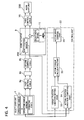
- FIG. 4 shows a control block diagram of the control unit 22 and its related units.
- the first and second control cables 8a and 8b, and the force transmittable adjuster 80 rotate the coupling shaft 12, so that the terminal 24 on the worm wheel 14 united with the shaft 12 moves with respect to the carbon resistance 25 to change a relative angle between them.
- This relative angle corresponding to an shift angle of the manual plate lever 20, is detected by the shift angle sensor 200 made up of the terminal 24 and the carbon resistance 25, which outputs a shift angle signal to the control unit 22.
- the control unit 22 includes a target position variation setting part 33, an actual position variation computing part 34, a motor torque calculating part 35, and a motor drive control part 45.
- the target position variation setting part 33 is electrically connected to the operating angle sensor 51 to receive its operating angle signal.
- the target position variation setting part 33 refers to a target position variation map shown in FIG. 9 and determines a target position variation based on the operating angle signal to output a target position variation signal to the motor torque calculating part 35.
- FIG. 8 shows the target position variation map having data on a relationship between a target position variation and an operating angle.
- the target position variations are set to have values determined according to a characteristic of detent force produced by the detent mechanism 350, and accordingly the values are different in the different operating directions BL and BP even in the same operating positions.
- the values of the variations are set to be zero in the P, R, N, D, and L positions, respectively.
- an arrow DCO indicates a direction where the first elastic member 8e is compressed and the second elastic member 8f is strained
- an arrow DEX indicates a direction where the first elastic member 8e is strained and the second elastic member 8f is compressed.
- the former state causes in a case when the select lever 2 is moved in the first direction BP and thereby the first control cable 8a moving in a direction indicated by an arrow BPa as shown in FIG. 1, while the latter state causes in a case when the select lever 2 is moved in the second direction BL and thereby the first control cable 8a moving in a direction indicated by an arrow BLb.
- the actual position variation computing part 34 is electrically connected to the operating angle sensor 51 and the shift angle sensor to receive an operating angle signal and a shift angle signal.
- the actual position variation computing part 34 computes an actual position variation based on a difference between the operating angle and the shift angle so as to output an actual position variation signal to the motor torque part 35.
- V A A OP - A SP ⁇ (W OP / W SP ), where V A is an actual variation between an operating angle A OP and a shift angle A SP , W OP is an operating angle difference between one select position and another one, and W SP is a shift angle difference between manual plate lever positions corresponding to the above select positions.
- the motor torque calculating part 35 receives the target position variation signal and the actual position variation signal and calculates a motor torque value so that a difference between the target position variation and the actual position variation becomes to be smaller, and outputs a motor torque command value signal to the motor drive control part 45.
- the motor torque calculating part 35 acts as a command assist value calculating part of the present invention.
- the motor drive control part 45 receives the motor torque command value signal from the motor torque calculating part 35 and outputs motor drive current determined based on the motor torque command value signal to the motor 15 so that the motor 15 generates target assist force under Power Width Modulation (PWM) control.
- PWM Power Width Modulation
- the motor 15 may be driven under other controls, such as current control or armature voltage control.
- the motor 15 applies motor torque to the coupling shaft 12 in order to obtain resultant force by adding the target assist force to the operating force of the driver in the select operation, thereby the resultant force moving the first, second, and third control cables 8a, 8b, and 18, the select lever 2, and the mode shift unit 300 to shift the operation modes of the automatic transmission 19.
- the mode shift unit 300 is driven to shift the modes of the automatic transmission 19, although its operating force becomes larger than that in a normal state.
- FIG. 5 shows a flowchart of an assist process executed in the control unit 22 in order to control the assist actuator 9 when the select lever 2 is operated by a driver.
- the operating angle sensor 51 detects an operating angle A OP of the select lever 2 and outputs an operating angle signal to the target position variation setting part 33 and the actual position variation computing part 34, and then the flow goes to step S2.
- the shift angle sensor 200 detects an shift angle A SP of the coupling shaft 12, corresponding to that of the manual plate lever 20, and outputs a shift angle signal to the actual position variation computing part 34, and then the flow goes to step S3.
- the target position variation setting part 33 refers to the target position variation map shown in FIG. 8 to set the target position variation V T based on the operating angle signal and outputs a target position variation signal to the motor torque calculating part 35, and then the flow goes to step S4.
- the actual position variation computing part 34 computes an actual position variation by a difference between the operating angle and the shift angle based on the operating angle signal and the shift angle signal, and outputs an actual position variation signal to the motor torque calculating part 35, and then the flow goes to step S5.
- the motor torque calculating part 35 calculates a motor torque value based on the target position variation signal and the actual position variation signal and outputs a motor torque command value signal to the motor drive control part 45, and then the flow goes to step S6.
- the motor drive control part 45 outputs motor drive current to the motor 15 under the PWM control based on the motor torque command value signal so as to drive the motor 15, and then the flow ends.
- operating force to move the select lever 2 and target operating reaction force are determined as follows.
- FIG. 6 shows characteristic relationships of operating reaction force Fm acting on the select lever 2, and a cam profile of the detent mechanism 350 with respect to the operating angle A OP , respectively, during the select operation from the P position to the R position.
- the operating reaction force Fm is calculated by using operating select torque detected by a torque sensor in a case where the motor 15 is not driven in the select operation from the Position to the R position.
- the reaction force Fm is generated by resultant force from the sum of friction force caused by the first, second, and third cables 8a, 8b, and 18, inertia force of the motor 15, spring force of the detent mechanism 350, and others.
- the reaction force Fm increases in a direction opposite to the operating direction of the lever 2 as a function of the operating angle A OP and reaches its peak Fma before the detent pin 29 reaches the top portion 27a of the cam 270 formed on detent plate 27 as shown in FIG. 6, and then decreases with increasing the angle A OP in this pullback zone.
- the reaction force Fm acts on the select lever 2 against the operating force inputted by the driver until the neutral position, because the detent plate 27 is biased by the spring force of the spring plate 28 in a direction opposite to the operating direction.
- the operating force in the opposite direction is affected by not only the deformation amount of the spring plate 28, but also the cam profile.
- the above-described decrease of the resistance force Fm results from a slight slope of the cam 270.
- the operating force inputted from the select lever 2 needs to overcome the reaction force Fm generated by the spring force of the spring plate 28 and the cam profile, in order to move the select lever 2 in the operating direction.
- the spring plate 28 After the detent pin 29 passes over the peak, the spring plate 28 starts to reduce its deformation amount until the pin 29 reaches the bottom of the cam 270 corresponding to the R position.
- the detent plate 27 is pressed by the spring plate 28 in the operating direction, so that the lever 2 is assisted to move forward by the reaction force Fm. Accordingly, the select lever 2 is propelled by the reaction force Fm, increasing at first and then decreasing, in such a way that the lever 2 is pulled into the bottom portion 27b corresponding to the R position.
- the operating force to be applied from the select lever 2 needs to be larger than and overcome the reaction force Fm shown in FIG. 6 in order to manually move the select lever 2 for an select operation without assist force of the motor 15.
- FIG. 7 is a schematic diagram showing target reaction force Ft with respect to the operating angle A OP when the select lever 2 is shifted from the P position to the R position.
- This target reaction force Ft is set as shown in FIG. 7 so as to bring a driver favorable operationality by providing nice click-feeling during the select operation.
- the target reaction force Ft is set to have a pull-back zone where the target resistance force Ft acts against the operating direction of the lever 2, indicated by a line Ft over a horizontal axis of the operating angle in FIG. 7, a neutral poison on the horizontal axis, and a pull-in zone where the target resistance force Ft acts in the operating direction, indicated by the line Ft under the horizontal axis.
- the target reaction force Ft increases at first and then decreases, although their acting directions are different from each other.
- the assist control is executed based on a target position variation and an actual position variation so that resultant force of assist force added from the motor 15 and operating force inputted by a driver overcomes the resistance force Fm shown in FIG. 6 and the driver receives the target resistance force Ft shown in FIG. 7.
- This assist control brings favorable operationality.
- detent force produced by the detent mechanism 350 acts as check force providing a driver with a clicking feeling during his or her select operation through the select lever 2.
- the select lever 2 is kept positioned stably in one of the select position in a state where the detent pin 29 is pressed by the detent force produced by the spring plate 28 so as to be halted at the corresponding bottom portion of the cam 270 formed on the detent plate 27.
- a checking mechanism may be mounted on the select lever unit 1 in addition to the detent mechanism 350 mounted on the automatic transmission 19. This addition of the checking mechanism, however, requires high installation precision of the checking mechanism and the detent mechanism 350, because they need to be synchronized to be positioned stably in their corresponding positions when operating force is zero.
- the force transmittable adjuster 80 has the cylinder 8d and the piston 8c that are slidable with respect to each other so as to cause play for adjusting misalignment between the checking mechanism and the detent mechanism 350. Accordingly, the play enables the stable state range to expand, but has the following problem.
- the amount of the play is preferably set to be a half of the maximum play caused by the checking mechanism and the detent mechanism 350 in the stable positions where operating force is zero, in a case where the mechanisms moves in synchronization with each other with having the play, since the select lever 2 is operated in the first and second directions BP and BL as shown in FIGS. 1 and 8.
- This play setting also needs high installation precision, resulting in difficult assembly.
- the play is set larger than the above setting, and the force transmittable adjuster 80 is provided with the first and second elastic members 8e and 8f at the both side of the piston 8c.
- One of the first and second elastic members 8e and 8f produces reaction force against the select lever 2 and acts to decrease the amount of the play. This brings a driver to feel reaction force against the select lever 2 and decreases the play, providing favorable operation feeling.
- the select lever 2 becomes heavy for its operation, due to reaction force caused by detent force of the detent mechanism 350 and transmitted through the first, second, and third control cables 8a, 8b, and 18, and the manual plate lever 20 of the automatic transmission 19.
- the manual plate lever 20 can not follow the operation of the select lever 2 sufficiently. Therefore, these positions are detected as a shift angle and an operating angle in order to control the assist actuator 9. Specifically, the operating angle of the select lever 2 is detected by the operating angle sensor 51, and the shift angle corresponding to that of the manual plate lever 20 is detected by the shift angle sensor 200. These detected angles are sent to the control unit 22, which controls the assist actuator 9 to output assist force so that a position variation becomes a predetermined value. This control can decrease reaction force acting on the select lever 2, resulting in a favorable light select operation.
- the target position variation setting part 33 sets a target position variation according to a detected operating angle as shown in FIG. 8.
- the target position variation in a select operation in the second direction BL is indicated by a full line
- the target position variation in a select operation in the first direction BL is indicated by a broken line.
- the motor torque calculating part 35 determines a motor torque value for driving the motor 15 so that an actual position variation computed in the actual position variation computing part 34 becomes closer to the target position variation. This control provides a favorable select operation feeling which is preset and close to an ideal one.
- the target position variation setting part 33 is provided with the target position variation map, whose values are determined according to operating directions, respectively. This enables finely setting of the target position variations according to each inputted operating force and operating direction, thereby obtaining the favorable operation feeling in both operating directions.
- the select lever 2 is in a stable state, when its operation is stopped in one of the select positions P to L. Then, the lever 2 is operated from the stable state, one of the first and second elastic members 8e and 8f is compressed and the other of them is strained, which produces elastic force and transmits operating force to the manual plate lever 20 through the second and third control cables 8b and 18, and the others.
- the manual plate lever 20 rotates the detent plate 27 together with it against detent force generated by the detent mechanism 350. Accordingly, the select lever 2 receives resultant force of the detent force and the elastic force, which provides a driver with a clicking feeling, resulting in removal of a checking mechanism of the select lever unit 1.
- the force transmittable adjuster 80 When the select lever 2 is halted in a select position without inputted operating force, the force transmittable adjuster 80 has a proper length as shown in an upper half portion of FIG. 9. Then, when the lever 2 is moved by operating force, the force transmittable adjuster 80 changes its length by deforming the first and second elastic members 8e and 8f and transmits the operating force from the first control cable 8a to the second control cable 8b by the elastic members 8e and 8f so as to rotate the manual plate lever 20 through the third control cable 18.
- the first elastic member 8e compresses and the second elastic 8f extends so as to increase the length of the force transmittable adjuster 80 when the lever 2 is shifted toward a desired select position shown in a lower half portion of FIG. 9.
- This deformations of the elastic members 8e and 8f cause elastic force to transmit the operating force between the first and second control cables 8a and 8b.
- the elastic members 8e and 8f returns to its original state shown in the upper half portion of FIG. 9, and the length of the force transmittable adjuster 80 is shorten from the not-shown extended length to the original length shown in the upper half portion of FIG. 9.
- This operating position select device 100 of the first embodiment has many advantages described below.
- the select lever 2 can be shorter than a conventional one by approximately 150 mm at its portion projecting from a center console toward a passenger compartment without increasing an operating force applied to the select lever 2 so much. This brings a design freedom concerning an installation location of the select lever and/or a layout of a passenger compartment to be broadened.
- the force transmittable adjuster 80 can change its length by relatively moving of the piston 8c and the cylinder 8d between the first and second control cables 8a and 8b and transmit operating force and detent force between the select lever 2 and the manual plate lever 20 by the first or second elastic members 8e and 8f. This enables a checking mechanism of the select lever unit 1 to be removed, resulting in low manufacturing cost and can suppress deterioration of a operating feeling due to play of the control cables 8a, 8b, and 18.
- the assist control is performed based on a target position variation determined according to an operating angle of the select lever 2 and an actual position variation between the operating angle and a shift angle of the manual plate lever 20.
- This control can provide a driver with operating reaction force so that the operating reaction force becomes closer to target reaction force.
- the target position variation setting part 33 has the target position variation map, as shown in FIG. 8, having an independent value of the target position variation between the first and second operating direction BP and BL even at the same operating angle A OP . This can provide a driver with operating reaction force so that it becomes closer to target reaction force, resulting in a comfortable operation feeling for the driver.
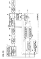
- This operating position select device is constructed similarly to that of the first embodiment shown in FIGS. 1 to 4 except a control unit 22.
- the control unit 22 includes a first motor torque calculating part 36, a second motor torque calculating part 37, and an adder 38.
- the first motor torque calculating part 36 is electrically connected to a target position variation setting part 33 that sets a target position variation based on an operating angle of a select lever and also to an actual position variation computing part 34 that computes an actual position variation based on the operating angle and a shift angle of a manual plate lever . It receives a target position variation signal and an actual position variation signal, and calculates a first motor torque command value based on a difference between the target position variation and the actual position variation so as to drive an electric motor 15 of an assist actuator under Proportional-Integral (PI) control.
- PI Proportional-Integral
- the second motor torque calculating part 37 is electrically connected to an operating angle sensor 51 to receive an operating angle signal, and is provided with a motor torque map having data on a relationship between an operating angle and second motor torque command values to obtain motor torque required for eliminating the target position variation as shown in FIG. 12. This second motor torque values are set independently between the first and second operating directions BP and BL even at the same operating angle.
- the second motor torque calculating part 37 refers to the motor torque map and calculates a second motor torque command value based on the operating angle signal so as to drive the motor 15 under feedforward control.
- the adder 38 is electrically connected to the first and second motor torque calculating parts 36 and 37 to receive a first motor torque command value signal and a second motor torque command value signal from them, respectively, and adds the first motor torque command value signal and the second motor torque command value signal to output a motor torque command value signal to a motor drive control part 45.
- the first and second motor torque calculating parts 36 and 37, and the adder 38 act as a command assist value calculating part of the present invention.
- the first motor torque calculating part 36 acts as a first command assist value calculating part of the present invention
- the second motor torque calculating part 37 acts as a second command assist value calculating part of the present invention.
- the other parts of the operating position select device of the second embodiment are similar to those of the first embodiment.
- FIG. 11 is a flowchart of the assist control executed by the control unit 22.
- the operating angle sensor 51 detects an operating angle A OP and outputs an operating angle signal to the target reaction force setting part 33 and the actual position variation computing part 34, and then the flow goes to step S12.
- a shift angle sensor 200 detects a shift angle A SP and outputs a shift angle signal to the actual position variation setting part 34, and then the flow goes to step S13.
- the target position variation setting part 33 refers to the target position variation map and sets a target position variation V T based on the operating angle A OP , and then the flow goes to step S14.
- the actual position variation computing part 34 computes an actual position variation V A based on the operating angle A OP and the shift angle A SP , and then the flow goes to step S15.
- the first motor torque calculating part 36 calculates a first motor torque command value T M1 based on a difference between the target position variation V T and the actual position variation V A and outputs a first motor torque command value signal to the adder 38, and then the flow goes to step S16.
- the second motor torque calculating part 37 sets a second motor torque command value T M2 based on the operating angle A OP referring to the motor torque map and outputs a second motor torque command value signal to the adder 38, and then the flow goes to step S17.
- the adder 38 adds the first motor torque command value T M1 and the second motor torque command value T M2 and output its sum as a motor torque command value T M to the motor drive control part 45, and then the flow goes to step S18.
- the motor drive control part 45 outputs motor drive current determined based on the motor torque command value T M to the motor 15, thereby the motor 15 applying assist force under P MW control to the select lever, and then the flow ends.
- This operating position select device has advantages similar to those of the first embodiment.
- the second motor torque calculating part 37 determines a first motor torque command value TM2 based on an operating angle referring to the motor torque map so as to drive the motor 15.
- This second motor torque command value is used as a command value for the feedforward control in the select-lever assist control, which can improve tracking ability of the assist control in comparison with PI control using an actual position variation and executed only by the first motor torque calculating part 36, for example.
- this operating position select device can provide a driver with a favorable operation feeling.
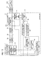
- This operating position select device is constructed similarly to that of the second embodiment shown in FIG. 10 except a select lever unit 1 and a control unit 22.
- the select lever unit 1 is provided with a pressure sensor 52 on a knob mounted on a select lever.
- the control unit 22 includes a position variation learning 40 electrically connected to the pressure sensor 52 and an actual position variation computing part 34, a target position variation setting part 41 electrically connected to an operating angle sensor 51 and the position variation learning part 40, a first motor torque calculating part 39 electrically connected to the target position variation setting part 41 and the actual position variation computing part 34, and a second motor torque calculating part 37 electrically connected to the operating angle sensor 51.
- the pressure sensor 52 detects pressure acting on the knob by a driver's hand and outputs a pressure signal to the position variation learning part 40.
- the pressure sensor 52 acts as an operation state detector of the present invention, and the pressure signal corresponds to a non-operation signal of the present invention.
- the position variation learning part 40 reads the pressure from the pressure sensor 52 and judges based on the pressure signal whether or not the select lever is operated. When it judges that the lever is not operated, the position variation learning part 40 learns a target position variation and outputs its revised value to the target position variation setting part 41 so as to change data of its target position variation map. On the other hand, when it judges that the lever is being operated, the position variation learning part 40 changes no data on the target position variation.
- the target position variation setting part 41 changes the data of the target position variation map according to the revised value outputted from the position variation learning part 40, and outputs the target position variation determined based on the operating angle to the first motor torque calculating part 39.
- the position variation learning part 40 and the target position variation setting part 41 act as a data revising part of the present invention.
- the first and second motor torque calculating parts 39 and 37, and the adder 38 act as a command assist value calculating part of the present invention.
- the first motor torque calculating part 39 acts as a first command assist value calculating part of the present invention
- the second motor torque calculating part 37 act as a second command assist value calculating of the present invention.
- the other parts of the operating position select device of the third embodiment are similar to those of the first and second embodiments.
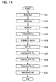
- the control unit 22 executes a flowchart, shown in FIG. 14, of assist control as follows.
- the operating angle sensor 51 detects an operating angle A OP and outputs an operating angle signal to the target reaction force setting part 41, the actual position variation computing part 34, and the second motor torque calculating part 37, and then the flow goes to step S22.
- a shift angle sensor 200 detects a shift angle A SP and outputs a shift angle signal to the actual position variation setting part 34, and then the flow goes to step S23.
- the pressure sensor 52 detects pressure PK acting on the knob of the select lever and outputs a pressure signal to the position variation learning part 40, and then the flow goes to step S24.
- the actual position variation computing part 34 computes an actual position variation V A based on the operating angle A OP and the shift angle A SP , and then the flow goes to step S25.
- the position variation learning part 40 learns an actual position variation in a case where the select lever is not operated and outputs a revised value for changing the data of the target position variation used in the target position variation map of the target position variation setting part 41, and then the flow goes to step S26.
- the target position variation setting part 41 refers to the target position variation map whose data is changed according to the revised value and sets a target position variation V T based on the operating angle A OP , and then the flow goes to step S27.
- the first motor torque calculating part 39 calculates a first motor torque command value T M1 based on a difference between the target position variation V T and the actual position variation V A and outputs a first motor torque command value signal to the adder 38, and then the flow goes to step S28.
- the second motor torque calculating part 37 sets a second motor torque command value TM2 based on the operating angle A OP referring to the motor torque map and outputs a second motor torque command value signal to the adder 38, and then the flow goes to step S29.
- the adder 38 adds the first motor torque command value TM1 and the second motor torque command value TM2 and outputs its sum as a motor torque command value TM to a motor drive control part 45, and then the flow goes to step S30.
- the motor drive control part 45 outputs motor drive current determined based on the motor torque command value TM to the motor 15, thereby the motor 15 applying assist force under PMW control to the select lever, and then the flow ends.
- the operating position select device has a first, second, and third control cables, and the force transmitting adjuster, which becomes longer than their original length due to change over time or heat generated during operation in some cases.
- FIG. 15 shows a schematic diagram illustrating behavior of the select lever 2, the first, second, and third control cables 8a, 8b, and 18, the force transmitting adjuster 80 and a manual plate lever 20 in a state where deformation of elastic members 8e and 8f used in a force transmittable adjuster 80 does not cause, in a state where it causes, and in a state where it is eliminated by assist control, when the select lever 2 is positioned in certain select position.
- FIG. 15 shows in a case where the select lever 2 and a manual plate lever 20 of a mode shift unit 300 can move in synchronization with each other in a case, where the deformation of the elastic members 8e and 8f does not occurs when the lever 2 is positioned in one of the select positions and is not applied by operating force from a driver.
- a piston 8c and a cylinder 8d of the force transmittable adjuster 80 is kept to have an original state and length due to optimum adjustment of relations among the select lever 2, the manual plate lever 20, the control cables 8a, 8b, and 18, the force transmittable adjuster 80, and others.
- the first elastic member 8e is smaller in cross sectional area than the second elastic member 8f, since the first elastic member 8e has a hole for passing the first control cable 8a therethrough.
- an operating angle of the select lever 2 and a shift angle of the manual plate lever 20 differs, which is detected by the operating angle sensor 51, the shift angle sensor 200, and the actual position variation computing part 34.
- the motor drive control part 45 drives the motor 15 based on the actual position variation so as to perform assist control, thereby moving the manual plate lever 20.
- the above mentioned tilt of the lever 2 and tracking movement of the manual plate lever 20 may be repeated, which is unfavorable.
- the operating position select device of the third embodiment is, therefore, provided with the position variation learning part 40 so as to resolve the above problem.
- the position variation learning part 40 receives the actual position variation from the actual position variation computing part 34 and outputs a revised value to the target position variation setting part 41, when it detects no operating force acting on the lever 2 based on a pressure signal outputted from a pressure sensor 52.
- the target position variation setting part 41 changes the data of the position variation map based on the revised value.
- the target position variation is set referring to the changed target position variation map, which counts for the deformation of the elastic members 8e and 8f in the state shown in the intermediate portion of FIG. 15.
- the manual plate lever 20 is prevented from moving by the assist control based on the deformation of the elastic members 8e and 8f.
- the operating position select device of the third embodiment has the following advantage in addition to those of the first and second embodiments.
- the select device is provided with the pressure sensor 52 and the position variation learning part 40, which enables the select lever 2 and the manual plate lever 20 to be kept in a state before a driver's hand is taken off from the select lever even when the elastic members 8e and 8f and/or the cables 8a, 8b, and 18 become deformed due to change over time or heat generated during operation, for example.
- This operating position select device is constructed similarly to that of the second embodiment shown in FIG. 10 except a control unit 22.
- the control unit 22 has a second motor torque calculating setting part 42, which is composed of a second basic motor torque calculating part 421 electrically connected to an operating angle sensor 51, an operating velocity calculating part 422 electrically connected to the operating angle sensor 51, a second motor torque compensating part 423 electrically connected to the operating velocity calculating part 422, and a second torque adder 424 electrically connected to the second basic motor torque calculating part 421 and the second motor torque compensating part 423.
- the second basic motor torque calculating part 421 is provided with a second motor torque map having data on a relationships between an operating angle and a second motor torque command basic value.
- the second basic motor torque calculating part 421 refers to the second motor torque map to determine a second motor torque command basic value for feedforward control based on the operating angle outputted from the operating angle sensor 51 and outputs a second motor torque command basic value signal to the adder 424.
- the second motor torque command basic value and the second motor torque command basic value signal correspond to a command basic assist value and a command basic assist value of the present invention, respectively.
- the operating velocity calculating part 422 calculates operating velocity of a select lever based on an operating angle outputted from the operating angle sensor 51 and outputs its operating velocity signal to the second motor torque compensating part 423.
- the second motor torque compensating part 423 calculates a compensation value, which is set to be larger as the operating velocity becomes higher, based on the operating velocity signal and outputs a compensation value signal to the adder 424.
- the second motor torque compensating part 423 acts as a compensation calculating part of the present invention.
- the second torque adder 424 adds the compensation value to the second motor torque command basic value and outputs a second motor torque command value signal to an adder 38.
- the second torque adder 424 acts as a second command assist value compensating part of the present invention.
- a first motor torque calculating part 36 and second motor torque calculating part 42, and the adder 38 act as a command assist value calculating part of the present invention.
- the first motor torque calculating part 36 acts as a first command assist value calculating part of the present invention
- the second motor torque calculating part 42 act as a second command assist value calculating of the present invention.
- the other parts of the operating position select device of the third embodiment are similar to those of the first and second embodiments.
- the control unit 22 executes a flowchart of assist control similar to the flowchart of the second embodiment shown in FIG. 11 except it has a flowchart for the feedback control instead of the step S16 in FIG 11.
- FIG. 17 shows the flowchart for the feedforward control.
- the control unit 22 executes the steps S11 to S15 of FIG. 11, and then step S31 of FIG. 17.
- the operating velocity calculating part 422 calculates operating velocity VOP based on an operating angle outputted from the operating angle sensor 51 and outputs its operating velocity signal to the second motor torque compensating part 423, and then the flow goes to step S32.
- the second basic motor torque calculating part 421 refers to the second motor torque map to determine a second motor torque command basic value T MB for the feedforward control based on the operating angle outputted from the operating angle sensor 51 and outputs a second motor torque command basic value signal to the adder 424, and then the flow goes to step S33.
- the second motor torque compensating part 423 calculates a compensation value TMC based on the operating velocity signal and outputs a compensation value signal to the adder 424, and then the flow goes to step S34.
- the second torque adder 424 adds the compensation value TMC to the second motor torque command basic value T MB to obtain a second motor torque command value TM2 and outputs a second motor torque command value signal to the adder 38, and then the flow goes to the step S17 of FIG. 11.
- the operating position select device of the fourth embodiment has the following advantage in addition to the advantages of the first and second embodiments.
- the second basic motor torque calculating part 421, the operating velocity calculating part 422, the second motor torque compensating part 423, and the second torque adder 424 can perform the feedforward control accounted for the operating velocity of the select lever, thereby improving its tracking ability of the manual lever plate 20 with respect to the operation of the select lever. This can provide a driver with a more favorable operating feeling.
- the operating position may be detected by the displacement amount of the select lever 2 or the mechanically connecting mechanism that connects the select lever 2 and the mode shift unit 300 with each other instead of the operating angle of the select lever 2.
- the shift position of the manual plate lever 20 may be detected by the displacement amount of the third control cable 18 or the like instead of the shift angle.
- the mechanically connecting mechanism may be rods or linkage instead of the first and second control cables 8a, 8b, and 18 in the above embodiments.
- the select lever may be of a shape different from the above embodiments.
- the select lever 2 may have a configuration different from that of the first embodiment shown in FIG. 1, for example, a finger- controllable one.
- the configuration of the cam of the detent mechanism may be formed arbitrarily to have different target reaction force.
- the elastic members 8e and 8f of the torque transmitting adjuster 80 may be made of material different from rubber and/or configuration, a metal spring for example.
- the torque transmitting adjuster 80 may have only one elastic member instead of two members 8e and 8f.
- the torque transmittable adjuster 80 may have a clearance between the elastic member/members and the select lever, or between the elastic member/members and cylinder.
- the piston 8c and the cylinder 8d may be replaced by members that have play for changing its own length, whose configurations are arbitrary.
Landscapes
- Engineering & Computer Science (AREA)
- General Engineering & Computer Science (AREA)
- Mechanical Engineering (AREA)
- Gear-Shifting Mechanisms (AREA)
- Control Of Transmission Device (AREA)
- Arrangement Or Mounting Of Control Devices For Change-Speed Gearing (AREA)
Applications Claiming Priority (2)
| Application Number | Priority Date | Filing Date | Title |
|---|---|---|---|
| JP2004152333 | 2004-05-21 | ||
| JP2004152333A JP2005331080A (ja) | 2004-05-21 | 2004-05-21 | 自動変速機のセレクトアシスト装置 |
Publications (2)
| Publication Number | Publication Date |
|---|---|
| EP1598577A2 true EP1598577A2 (de) | 2005-11-23 |
| EP1598577A3 EP1598577A3 (de) | 2009-12-30 |
Family
ID=34942314
Family Applications (1)
| Application Number | Title | Priority Date | Filing Date |
|---|---|---|---|
| EP05291076A Withdrawn EP1598577A3 (de) | 2004-05-21 | 2005-05-19 | Positionswahleinrichtung für ein automatisches Getriebe |
Country Status (3)
| Country | Link |
|---|---|
| US (1) | US20050257637A1 (de) |
| EP (1) | EP1598577A3 (de) |
| JP (1) | JP2005331080A (de) |
Cited By (1)
| Publication number | Priority date | Publication date | Assignee | Title |
|---|---|---|---|---|
| WO2007063773A1 (ja) * | 2005-11-30 | 2007-06-07 | Calsonic Kansei Corporation | 自動変速機のセレクトアシスト装置 |
Families Citing this family (7)
| Publication number | Priority date | Publication date | Assignee | Title |
|---|---|---|---|---|
| JP2004203088A (ja) * | 2002-12-24 | 2004-07-22 | Calsonic Kansei Corp | 車両用自動変速装置 |
| JP2005106100A (ja) * | 2003-09-29 | 2005-04-21 | Calsonic Kansei Corp | 自動変速機のセレクトアシスト装置 |
| ES2357411T3 (es) * | 2005-12-23 | 2011-04-26 | Innovius B.V. | Dispositivo de cambio de engranaje para aplicaciones motorizadas. |
| JP2007336663A (ja) * | 2006-06-14 | 2007-12-27 | Denso Corp | 位置切換制御装置 |
| US9482289B2 (en) | 2013-10-14 | 2016-11-01 | Club Car, Llc | Self-preloading shift lever |
| US9970538B2 (en) * | 2016-05-13 | 2018-05-15 | Dura Operating, Llc | Method for controlling an electromechanical interface device |
| JP2022150876A (ja) * | 2021-03-26 | 2022-10-07 | 株式会社アイシン | シフト装置 |
Citations (2)
| Publication number | Priority date | Publication date | Assignee | Title |
|---|---|---|---|---|
| JPH09323559A (ja) | 1996-06-05 | 1997-12-16 | Nissan Motor Co Ltd | 自動変速機の操作装置 |
| JP2003097694A (ja) | 2001-09-27 | 2003-04-03 | Jatco Ltd | シフトバイワイヤシステム |
Family Cites Families (8)
| Publication number | Priority date | Publication date | Assignee | Title |
|---|---|---|---|---|
| US6193621B1 (en) * | 1999-05-06 | 2001-02-27 | Fanuc Robotics North America, Inc. | Take-up device for tensioning motion transmitting control cables |
| JP2002013634A (ja) * | 2000-06-29 | 2002-01-18 | Isuzu Motors Ltd | 変速機のシフトアシスト装置 |
| JP3980352B2 (ja) * | 2001-12-28 | 2007-09-26 | ジヤトコ株式会社 | トロイダル型無段変速機のトルクシフト補償装置 |
| JP2003301942A (ja) * | 2002-02-08 | 2003-10-24 | Calsonic Kansei Corp | 車両用自動変速装置 |
| US6918314B2 (en) * | 2002-05-31 | 2005-07-19 | Dura Global Technologies, Inc. | Shift-by-wire transmission actuator assembly |
| JP3724471B2 (ja) * | 2002-10-11 | 2005-12-07 | トヨタ自動車株式会社 | 自動変速機の故障判別装置および故障判別方法 |
| KR100507485B1 (ko) * | 2003-05-27 | 2005-08-17 | 현대자동차주식회사 | 자동 변속기의 솔레노이드 플런저 보정 제어장치 및 방법 |
| KR100507489B1 (ko) * | 2003-06-05 | 2005-08-17 | 현대자동차주식회사 | 차량의 변속 시스템 |
-
2004
- 2004-05-21 JP JP2004152333A patent/JP2005331080A/ja not_active Withdrawn
-
2005
- 2005-05-18 US US11/131,217 patent/US20050257637A1/en not_active Abandoned
- 2005-05-19 EP EP05291076A patent/EP1598577A3/de not_active Withdrawn
Patent Citations (2)
| Publication number | Priority date | Publication date | Assignee | Title |
|---|---|---|---|---|
| JPH09323559A (ja) | 1996-06-05 | 1997-12-16 | Nissan Motor Co Ltd | 自動変速機の操作装置 |
| JP2003097694A (ja) | 2001-09-27 | 2003-04-03 | Jatco Ltd | シフトバイワイヤシステム |
Cited By (1)
| Publication number | Priority date | Publication date | Assignee | Title |
|---|---|---|---|---|
| WO2007063773A1 (ja) * | 2005-11-30 | 2007-06-07 | Calsonic Kansei Corporation | 自動変速機のセレクトアシスト装置 |
Also Published As
| Publication number | Publication date |
|---|---|
| EP1598577A3 (de) | 2009-12-30 |
| US20050257637A1 (en) | 2005-11-24 |
| JP2005331080A (ja) | 2005-12-02 |
Similar Documents
| Publication | Publication Date | Title |
|---|---|---|
| EP1647743B1 (de) | Positionswahleinrichtung für ein automatisches Getriebe | |
| EP1437533B1 (de) | Wählhebel für Automatikgetriebe | |
| US6477910B2 (en) | Adjustment system in an automatic transmission | |
| EP1598577A2 (de) | Positionswahleinrichtung für ein automatisches Getriebe | |
| US7367244B2 (en) | Operating position select device for automatic transmission | |
| US7194927B2 (en) | Operating position select device for automatic transmission | |
| US7426881B2 (en) | Operating position select device for automatic transmission | |
| US20060011003A1 (en) | Operating position select device for automatic transmission | |
| US20050066759A1 (en) | Operating position select device for automatic transmission | |
| US6877390B2 (en) | Shift range changeover mechanism | |
| US7243567B2 (en) | Operating position select device for automatic transmission | |
| EP1336774B1 (de) | Rastprofil zur Sicherung der Schaltstellungen | |
| EP1433986B1 (de) | Automatikgetriebevorrichtung für Kraftfahrzeug mit einer Hilfskraftunterstützung für den Positionswählhebel | |
| EP1591697A2 (de) | Positionswahleinrichtung für ein automatisches Getriebe | |
| JP2003130213A (ja) | 作業車両の変速装置 | |
| US20030126941A1 (en) | Clutch pedal designed to equip a motor vehicle | |
| JP2009196436A (ja) | チルト式ステアリング装置 | |
| US20060094565A1 (en) | Operating position select device for automatic transmission | |
| US20070068304A1 (en) | Operating position select device adapted for automatic transmission | |
| JP7380466B2 (ja) | 車両用パーキングロック機構 | |
| EP3943784B1 (de) | Fahrzeugparksperrmechanismus | |
| US20050217405A1 (en) | Selector apparatus of an automatic transmission of vehicle | |
| US20090082932A1 (en) | Select Assist Device for Automatic Transmission | |
| HK1060169A1 (en) | A control system for a robotized gearbox in a motor vehicle, with the ability to learn the position of the ratios or gears |
Legal Events
| Date | Code | Title | Description |
|---|---|---|---|
| PUAI | Public reference made under article 153(3) epc to a published international application that has entered the european phase |
Free format text: ORIGINAL CODE: 0009012 |
|
| AK | Designated contracting states |
Kind code of ref document: A2 Designated state(s): AT BE BG CH CY CZ DE DK EE ES FI FR GB GR HU IE IS IT LI LT LU MC NL PL PT RO SE SI SK TR |
|
| AX | Request for extension of the european patent |
Extension state: AL BA HR LV MK YU |
|
| PUAL | Search report despatched |
Free format text: ORIGINAL CODE: 0009013 |
|
| AK | Designated contracting states |
Kind code of ref document: A3 Designated state(s): AT BE BG CH CY CZ DE DK EE ES FI FR GB GR HU IE IS IT LI LT LU MC NL PL PT RO SE SI SK TR |
|
| AX | Request for extension of the european patent |
Extension state: AL BA HR LV MK YU |
|
| STAA | Information on the status of an ep patent application or granted ep patent |
Free format text: STATUS: THE APPLICATION IS DEEMED TO BE WITHDRAWN |
|
| 18D | Application deemed to be withdrawn |
Effective date: 20091202 |