EP1598563B1 - Verbindersystem - Google Patents
Verbindersystem Download PDFInfo
- Publication number
- EP1598563B1 EP1598563B1 EP04011750A EP04011750A EP1598563B1 EP 1598563 B1 EP1598563 B1 EP 1598563B1 EP 04011750 A EP04011750 A EP 04011750A EP 04011750 A EP04011750 A EP 04011750A EP 1598563 B1 EP1598563 B1 EP 1598563B1
- Authority
- EP
- European Patent Office
- Prior art keywords
- connector system
- profile
- screw
- threaded sleeve
- connecting screw
- Prior art date
- Legal status (The legal status is an assumption and is not a legal conclusion. Google has not performed a legal analysis and makes no representation as to the accuracy of the status listed.)
- Expired - Lifetime
Links
- 239000000853 adhesive Substances 0.000 claims description 3
- 230000001070 adhesive effect Effects 0.000 claims description 3
- 229910052782 aluminium Inorganic materials 0.000 claims description 2
- XAGFODPZIPBFFR-UHFFFAOYSA-N aluminium Chemical compound [Al] XAGFODPZIPBFFR-UHFFFAOYSA-N 0.000 claims description 2
- 239000012530 fluid Substances 0.000 claims description 2
- 229910052751 metal Inorganic materials 0.000 claims description 2
- 239000002184 metal Substances 0.000 claims description 2
- 235000011837 pasties Nutrition 0.000 claims description 2
- 239000000126 substance Substances 0.000 claims description 2
- 239000004411 aluminium Substances 0.000 claims 1
- 238000009434 installation Methods 0.000 claims 1
- 238000003780 insertion Methods 0.000 abstract description 7
- 230000037431 insertion Effects 0.000 abstract description 7
- 238000000034 method Methods 0.000 description 7
- 239000003795 chemical substances by application Substances 0.000 description 2
- 238000004873 anchoring Methods 0.000 description 1
- 230000004323 axial length Effects 0.000 description 1
- 238000011161 development Methods 0.000 description 1
- 230000018109 developmental process Effects 0.000 description 1
- 239000004922 lacquer Substances 0.000 description 1
- 230000035515 penetration Effects 0.000 description 1
- 229920001296 polysiloxane Polymers 0.000 description 1
- 238000010079 rubber tapping Methods 0.000 description 1
Images

Classifications
-
- F—MECHANICAL ENGINEERING; LIGHTING; HEATING; WEAPONS; BLASTING
- F16—ENGINEERING ELEMENTS AND UNITS; GENERAL MEASURES FOR PRODUCING AND MAINTAINING EFFECTIVE FUNCTIONING OF MACHINES OR INSTALLATIONS; THERMAL INSULATION IN GENERAL
- F16B—DEVICES FOR FASTENING OR SECURING CONSTRUCTIONAL ELEMENTS OR MACHINE PARTS TOGETHER, e.g. NAILS, BOLTS, CIRCLIPS, CLAMPS, CLIPS OR WEDGES; JOINTS OR JOINTING
- F16B7/00—Connections of rods or tubes, e.g. of non-circular section, mutually, including resilient connections
- F16B7/18—Connections of rods or tubes, e.g. of non-circular section, mutually, including resilient connections using screw-thread elements
- F16B7/187—Connections of rods or tubes, e.g. of non-circular section, mutually, including resilient connections using screw-thread elements with sliding nuts or other additional connecting members for joining profiles provided with grooves or channels
-
- F—MECHANICAL ENGINEERING; LIGHTING; HEATING; WEAPONS; BLASTING
- F16—ENGINEERING ELEMENTS AND UNITS; GENERAL MEASURES FOR PRODUCING AND MAINTAINING EFFECTIVE FUNCTIONING OF MACHINES OR INSTALLATIONS; THERMAL INSULATION IN GENERAL
- F16B—DEVICES FOR FASTENING OR SECURING CONSTRUCTIONAL ELEMENTS OR MACHINE PARTS TOGETHER, e.g. NAILS, BOLTS, CIRCLIPS, CLAMPS, CLIPS OR WEDGES; JOINTS OR JOINTING
- F16B2200/00—Constructional details of connections not covered for in other groups of this subclass
- F16B2200/20—Connections with hook-like parts gripping behind a blind side of an element to be connected
- F16B2200/205—Connections with hook-like parts gripping behind a blind side of an element to be connected the hook being a separate retainer
-
- F—MECHANICAL ENGINEERING; LIGHTING; HEATING; WEAPONS; BLASTING
- F16—ENGINEERING ELEMENTS AND UNITS; GENERAL MEASURES FOR PRODUCING AND MAINTAINING EFFECTIVE FUNCTIONING OF MACHINES OR INSTALLATIONS; THERMAL INSULATION IN GENERAL
- F16B—DEVICES FOR FASTENING OR SECURING CONSTRUCTIONAL ELEMENTS OR MACHINE PARTS TOGETHER, e.g. NAILS, BOLTS, CIRCLIPS, CLAMPS, CLIPS OR WEDGES; JOINTS OR JOINTING
- F16B2200/00—Constructional details of connections not covered for in other groups of this subclass
- F16B2200/40—Clamping arrangements where clamping parts are received in recesses of elements to be connected
- F16B2200/403—Threaded clamping parts
Definitions
- the invention relates to a connector system designed and determined for a profile connection comprising two profile bars made of metal, in particular aluminum, each having at least one longitudinal undercut profile groove, wherein the connector system comprises a connecting screw with a screw head and a screw shaft and a threaded sleeve, wherein the Connecting screw is dimensioned such that it passes through the threaded sleeve and can be brought with a part of its screw shaft on this for engagement in a counter-bearing piece in the profile of the second profile bar profile.
- Such connector systems are known in the art.
- the assembly of conventional connector systems in the profile of a profiled bar is conventionally carried out as follows:
- the threaded sleeve is screwed into the profiled groove, but before screwing the threaded sleeve, the connecting screw is inserted into the profile in the correct orientation.
- the connecting screw After screwing in the threaded sleeve, the connecting screw must be passed through the threaded sleeve.
- the connecting screw must be averaged so that it meets the inner bore of the threaded sleeve exactly without bumping on the bearing collar of the threaded sleeve.
- the object of the present invention is therefore to simplify the hitherto complex positioning of the connecting screw in the profile groove or to avoid accidental slipping of the connecting screw in the profile groove.
- a central idea of the present invention consists in avoiding slipping of the connecting screw by releasably fixing the connecting screw in the profiled groove. While there are already numerous advantages in terms of the inventive concept of releasably fixing the connecting screw in the profile groove in general, a releasable fixation of the connecting screw is provided within the threaded sleeve, so that connecting screw and threaded sleeve can be introduced together as an assembly unit in the profile. As a result, not only a releasable fixation of the connecting screw in the profile is achieved, but the assembly process is facilitated overall, since now no longer in two separate steps, first the connecting screw and then the threaded sleeve are introduced, but this is done in a single step. At the same time, the screw head of the connecting screw when inserting the threaded sleeve serve as a centering, so that the screwing of the threaded sleeve is facilitated or an oblique screwing is prevented.
- the effective during insertion of the threaded sleeve fixing between threaded sleeve and connecting screw can be solved before screwing the connecting screw in a counter-bearing piece in the profile of the second profile bar.
- the fixing means by applying the screw head of the connecting screw with a predetermined force can be solved.
- a predetermined torque to solve the fixing.
- an axial force preferably in the connecting direction, can also be exerted on the screw head, thus releasing a fixing means, in particular broken through or being pushed out of the threaded sleeve.
- the fixing means comprise a clamping piece, preferably made of plastic.
- the fixing agents may also comprise an adhesive and / or curing, fluid or pasty substance, for example based on a lacquer, silicone or adhesive.
- the connecting screw when screwing the connecting sleeve serve as a guide and / or centering.
- the connecting screw performs the threaded sleeve exactly parallel in the profile of the profile bar, so that an oblique screwing the threaded sleeve is avoided in the profile.
- Previously known threaded sleeves have a centering collar on the sleeve head, which is usually relatively short, as with each millimeter Zentrierbundin automatically available for a thread available length of the threaded sleeve is shortened.
- a threaded sleeve introduced by threading or tapping can very easily run obliquely into the profile groove if it is not guided exactly. This risk exists especially when the threaded sleeves of laymen are screwed.
- the connecting screw supports the guidance of the threaded sleeve, eliminates the entire problem, so that a centering collar on the front in the insertion direction of the threaded sleeve are no longer provided needs.
- a threaded sleeve without centering collar can be used.
- the connecting screw is positioned in the threaded sleeve on the fixing means so that it protrudes in the direction of insertion into the profile not only with its screw head, but also with a part of its screw shank.
- connecting screw projects beyond the threaded sleeve over at least half of its length of its screw shank.
- the clamping piece can in principle be in any suitable form for the application.
- the clamping piece comprises a plurality of clamping tabs, which are interconnected via a central connecting portion.
- the clamping tabs have a thickness of 0.3 to 0.5 mm, preferably of about 0.4 mm.
- the clamping piece is integrally formed.
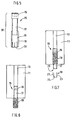
- FIG. 1 a profile connection, in which the present connector system can be used, is first of all illustrated.
- the connector system and designed as a sliding block 26 counter bearing piece two profile bars 11, 12 are screwed aligned orthogonal to each other.
- the profile bars 11, 12 each have at least one undercut profile groove 13, 14, here in each case four undercut profile grooves.
- a threaded sleeve 18 is screwed, which has an inner bore 27.
- a connecting screw 15 comprising a screw head 16 and a screw shaft 17 is guided such that the threaded sleeve 18 holds the connecting screw 15 in the profile groove 13 in the connecting direction.
- the connecting bolt 15 protrudes with its screw shank 17 over the threaded sleeve 18 so far that it dips into the profiled groove 14 of the second profiled bar 12 and engages in a slot nut 26 accommodated there.
- first and second profile bar 11, 12 can be firmly screwed together.
- the connector system which can be used for example for a profile connection as shown in Figure 1, illustrated in an exploded view.
- the connector system consists in the present embodiment concretely of three parts, namely the connecting screw 15, the threaded sleeve 18 and a fixing means, which is specifically designed here as a one-piece clamping piece 19 made of plastic.
- the connecting screw 15 can be releasably fixed in the inner bore 27 of the threaded sleeve 18.
- the clamping piece 19 can push out by applying a predetermined axial force on the screw head 16 in the connecting direction of the threaded sleeve 18, so that the connecting screw 15 is then rotationally movable relative to the threaded sleeve 18 and with the sliding block 26 can be screwed.
- the clamping piece 19 of Figure 2 is illustrated in a folded state in plan view.
- the clamping piece 19, which in the present embodiment integrally formed of plastic, preferably punched, may be four clamping tabs 21 to 24, which are connected to each other via a central connecting portion 25.
- a central recess 28 may be arranged in the central connecting portion 25.
- the remaining portion of the central connecting portion 25 serves as a footprint for the front end 29 of the screw shaft 17.
- the clamping piece 19 preferably has a thickness of about 0.4 mm. As illustrated in FIG.
- the clamping lugs 21 to 24 can be folded against each other, so that the front end 29 and the adjoining region of the screw shank 17 can be received in the clamping piece 19 and the clamping piece 19 folded in this way together with the front end 29 and one can be inserted into the inner bore 27 of the threaded sleeve 18 subsequent section of the screw shaft 17, as illustrated in the sectional view of Figure 5.
- the clamping piece is here in the inner bore 27 of the threaded sleeve 18 so far inserted, that at least still a tool engagement 30 which is formed in the inner bore 27, remains accessible to screw the connecting screw 15, threaded sleeve 18 and clamping piece 19 formed assembly unit 20 in the profile groove 13 of a profile bar 11 by means of a tool (not shown).
- the insertion of the mounting unit 20 in the profile groove 13 of the profile bar 11 is illustrated in Figure 6.
- the connecting screw 15 is in this case with more than half the length of its screw shank 17 on the threaded sleeve 18, so that is given by the connecting screw 15 is an extremely effective centering and insertion.
- the threaded sleeve 18 is subsequently screwed into the profile groove 13 of the profiled bar 11 in a thread pressing process to form a thread formed by deformation.
- the screwing of the threaded sleeve 18 in a Spanabhub avoiding Gewinded Wegrind is indeed preferred; but there are also other methods already proposed in the prior art to anchor a threaded sleeve 18 in a profile groove 13 of a section bar 11.
- Also further not yet proposed method for anchoring a threaded sleeve 18 in a profile groove 13 of a profile bar 11 come to be used.
- FIG. 7 schematically illustrates the threaded sleeve 18 already anchored in the profile groove 13, wherein the clamping piece 19 is pushed out of the threaded sleeve 18 in the axial direction by acting on the screw head 16 of the connecting screw 15, so that the connecting screw 15 is now rotationally opposite the threaded sleeve 18 is freely movable and protrudes with a part of its screw shaft 17 on the profile bar 11 for engagement in a sliding block 26 in a profile groove 14 of a second profiled bar 12 (see, see Figure 1).
Landscapes
- Engineering & Computer Science (AREA)
- General Engineering & Computer Science (AREA)
- Mechanical Engineering (AREA)
- Mutual Connection Of Rods And Tubes (AREA)
- Manipulator (AREA)
- Screw Conveyors (AREA)
- Paper (AREA)
- Quick-Acting Or Multi-Walled Pipe Joints (AREA)
- Details Of Connecting Devices For Male And Female Coupling (AREA)
Description
- Die Erfindung betrifft ein Verbindersystem ausgebildet und bestimmt für eine Profilverbindung umfassend zwei zu verbindende Profilstäbe aus Metall, insbesondere aus Aluminium, die jeweils mindestens eine längsverlaufende hinterschnittene Profilnut aufweisen, wobei das Verbindersystem eine Verbindungsschraube mit einem Schraubenkopf und einem Schraubenschaft sowie eine Gewindehülse umfasst, wobei die Verbindungsschraube derart bemessen ist, dass sie die Gewindehülse durchtritt und mit einem Teil ihres Schraubenschaftes über diese zum Eingriff in ein Gegenlagerstück in der Profilnut des zweiten Profilstabes gebracht werden kann.
- Derartige Verbindersysteme sind aus dem Stand der Technik bekannt. Die Montage herkömmlicher Verbindersysteme in der Profilnut eines Profilstabs erfolgt dabei herkömmlicherweise wie folgt: Die Gewindehülse wird in die Profilnut eingeschraubt, wobei allerdings vor Einschrauben der Gewindehülse die Verbindungsschraube in die Profilnut in der richtigen Orientierung einzuführen ist. Nach dem Eindrehen der Gewindehülse muss die Verbindungsschraube durch die Gewindehülse hindurchgeführt werden. Dabei muss die Verbindungsschraube so ausgemittelt werden, dass sie die Innenbohrung der Gewindehülse genau trifft ohne auf dem Lagerbund der Gewindehülse zu stoßen. Ist die Verbindungsschraube einmal korrekt eingeführt und wird sie wegen anderer Montagearbeiten nicht gleich mit einem Gegenlagerstück in der Profilnut des zweiten Profilstabes in Eingriff gebracht, besteht darüber hinaus das Risiko, dass die Verbindungsschraube erneut aus der Gewindehülse herausfällt, evtl., sofern die Profilnut des Profilstabes am distalen Ende im Montagevorgang endseitig offen ist sogar aus der Profilnut herausfällt. Dementsprechend kostet der Montagevorgang Zeit und ist relativ kompliziert und aufwendig zu automatisieren.
- Die Aufgabe der vorliegenden Erfindung besteht daher darin, die bislang aufwendige Positionierung der Verbindungsschraube in der Profilnut zu vereinfachen bzw. ein ungewolltes Verrutschen der Verbindungsschraube in der Profilnut zu vermeiden.
- Diese Aufgabe wird mit einem Verbindersystem nach den Merkmalen des Patentanspruches 1 gelöst. Vorteilhafte Weiterbildungen sind in den Unteransprüchen angegeben.
- Ein Kerngedanke der vorliegenden Erfindung besteht dabei darin, ein Verrutschen der Verbindungsschraube durch eine lösbare Fixierung der Verbindungsschraube in der Profilnut zu vermeiden. Während sich bereits zahlreiche Vorteile allein durch den erfindungsgemäßen Gedanken der lösbaren Fixierung der Verbindungsschraube in der Profilnut allgemein ergeben, ist speziell eine lösbare Fixierung der Verbindungsschraube innerhalb der Gewindehülse vorgesehen, so dass Verbindungsschraube und Gewindehülse gemeinsam als Montageeinheit in die Profilnut eingeführt werden können. Hierdurch wird nicht nur eine lösbare Fixierung der Verbindungsschraube in der Profilnut erreicht, sondern der Montagevorgang wird insgesamt erleichtert, da nun nicht mehr in zwei separaten Arbeitsschritten erst die Verbindungsschraube und dann die Gewindehülse eingebracht werden, sondern dies nun in einem einzigen Arbeitsschritt erfolgt. Gleichzeitig kann der Schraubenkopf der Verbindungsschraube beim Einführen der Gewindehülse als Zentriermittel dienen, so dass auch der Einschraubvorgang der Gewindehülse erleichtert wird bzw. ein schräges Einschrauben verhindert wird.
- Die beim Einführen der Gewindehülse wirksamen Fixiermittel zwischen Gewindehülse und Verbindungsschraube können vor Eindrehen der Verbindungsschraube in ein Gegenlagerstück in der Profilnut des zweiten Profilstabes gelöst werden.
- Zweckmäßigerweise sind die Fixiermittel durch Beaufschlagung des Schraubenkopfes der Verbindungsschraube mit einer vorbestimmten Kraft lösbar. Hierbei kann entweder durch Eingriff eines Werkzeuges in den Schraubenkopf ein vorbestimmtes Drehmoment die Fixiermittel lösen. Alternativ kann auch eine axiale Kraft, vorzugsweise in Verbindungsrichtung, auf den Schraubenkopf ausgeübt werden und so ein Fixiermittel gelöst, insbesondere durchbrochen oder aus der Gewindehülse hinausgeschoben werden. In einer ersten bevorzugten Ausgestaltung umfassen die Fixiermittel ein Klemmstück, vorzugsweise aus Kunststoff.
- In einer alternativen Ausgestaltung können die Fixiermittel auch eine klebende und/oder aushärtende, fluide oder pastöse Substanz umfassen, beispielsweise auf der Basis eines Lackes, Silikons oder Klebers.
- Wenn der Schraubenkopf eine gewisse axiale Länge aufweist und in seinem Durchmesser auf den Innendurchmesser der Profilnut des Profilstabes abgestimmt ist, was nach einer speziellen Ausgestaltung der vorliegenden Erfindung bevorzugt wird, kann die Verbindungsschraube beim Einschrauben der Verbindungshülse als Führungs- und/oder Zentrierelement dienen. Damit führt die Verbindungsschraube die Gewindehülse exakt parallel in der Profilnut des Profilstabes, so dass ein schräges Eindrehen der Gewindehülse in die Profilnut vermieden wird. Bisher bekannte Gewindehülsen haben am Hülsenkopf einen Zentrierbund, welcher meist relativ kurz bemessen ist, da mit jedem Millimeter Zentrierbundlänge automatisch die für ein Gewinde zur Verfügung stehendes Länge der Gewindehülse verkürzt wird. Mit einem Zentrierbund muss daher immer ein Kompromiss auf Kosten der Einschraubfestigkeit der Gewindehülse eingegangen werden. Eine durch Gewindeschneiden oder Gewindeformen eingebrachte Gewindehülse kann sehr leicht schräg in die Profilnut einlaufen, wenn sie nicht exakt geführt wird. Dieses Risiko besteht besonders dann, wenn die Gewindehülsen von Laien eingedreht werden.
- Da nach dem hier beschriebenen vorteilhaften Aspekt der Erfindung die Verbindungsschraube die Führung der Gewindehülse unterstützt, entfällt die gesamte Problematik, so dass auch ein Zentrierbund auf der in Einführrichtung vorne liegenden Seite der Gewindehülse nicht mehr vorgesehen werden braucht. Nach einem Aspekt der vorliegenden Erfindung kann daher auch eine Gewindehülse ohne Zentrierbund eingesetzt werden.
Nach einem weiteren Aspekt der vorliegenden Erfindung wird die Verbindungsschraube in der Gewindehülse über die Fixiermittel so positioniert, dass sie in Einführrichtung in die Profilnut nicht nur mit ihrem Schraubenkopf, sondern auch mit einem Teil ihres Schraubenschaftes vorsteht. Durch den dann längeren Abstand des Schraubenkopfes zur Hülse wird die Führung parallel zur Profilnut beim Eindrehen noch wesentlich verbessert. Eine im Wesentlichen parallele Führung wird aufgrund des vergrößerten Abstands auch dann erreicht, wenn ein gewisses Spiel zwischen dem Außendurchmesser des Schraubenkopfes und dem Innendurchmesser der Profilnut gegeben ist. - Besonders bevorzugt wird eine Ausgestaltung, in der die Verbindungsschraube mindestens über die Hälfte ihrer Länge ihres Schraubenschaftes über die Gewindehülse vorsteht.
- Das Klemmstück kann prinzipiell in irgendeiner, für den Anwendungsfall geeigneten Form vorliegen. In einer speziellen, keineswegs jedoch zwingenden Ausgestaltung umfasst das Klemmstück mehrere Klemmlappen, die über einen zentralen Verbindungsabschnitt miteinander verbunden sind.
- In einer speziellen Ausgestaltung weisen die Klemmlappen dabei eine Stärke von 0,3 bis 0,5 mm vorzugsweise von etwa 0,4 mm auf.
- Nach einem ebenfalls bevorzugten, keineswegs jedoch zwingenden Aspekt der Erfindung ist das Klemmstück einstückig ausgebildet.
- Die Erfindung wird nachstehend auch hinsichtlich weiterer Merkmale und Vorteile anhand der Beschreibung von Ausführungsbeispielen und unter Bezugnahme auf die beiliegenden Zeichnungen näher erläutert.
- Hierbei zeigen:
- Figur 1
- eine an sich bekannte Profilverbindung, bei der ein Verbindersystem gemäß der vorliegenden Erfindung Verwendung finden kann
- Figur 2
- eine Ausführungsform des Verbindersystems nach der vorliegenden Erfindung zusammen mit einem Nutenstein in einer Explosionsansicht
- Figur 3
- das beim Verbindersystem nach Figur 2 verwendete Fixiermittel, aufgeklappt, in Draufsicht
- Figur 4
- das Fixiermittel nach Figur 3 in einer Seitenansicht, in Montageposition zusammengefaltet
- Figur 5
- eine Schnittansicht durch das Verbindersystem aus Figur 2
- Figur 6
- eine schematische Ansicht des bereits teilweise in die Profilnut eines Profilstabes eingeführten Verbindersystems gemäß Figur 5
- Figur 7
- das Verbindersystem nach Figur 6 nach Eindringen in die Profilnut
- In Figur 1 ist zunächst eine Profilverbindung, bei der das vorliegende Verbindersystem Anwendung finden kann, veranschaulicht. Über das Verbindersystem und ein als Nutenstein 26 ausgebildetes Gegenlagerstück werden zwei Profilstäbe 11, 12 orthogonal zueinander ausgerichtet verschraubt. Die Profilstäbe 11, 12 weisen jeweils mindestens eine hinterschnittene Profilnut 13, 14, hier konkret jeweils vier hinterschnittene Profilnuten auf. In die Profilnut 13, des ersten Profilstabes 11 ist eine Gewindehülse 18 eingeschraubt, die eine Innenbohrung 27 aufweist. Durch diese Innenbohrung 27 ist eine Verbindungsschraube 15 umfassend einen Schraubenkopf 16 und einen Schraubenschaft 17 geführt derart, dass die Gewindehülse 18 die Verbindungsschraube 15 in der Profilnut 13 in Verbindungsrichtung festhält. Die Verbindungsschraube 15 steht mit ihrem Schraubenschaft 17 über die Gewindehülse 18 soweit über, dass sie in die Profilnut 14 des zweiten Profilstabes 12 eintaucht und in einen dort aufgenommenen Nutenstein 26 eingreift. Bei Anziehen der Verbindungsschraube 15 können erster und zweiter Profilstab 11, 12 fest miteinander verschraubt werden.
- In Figur 2 ist das Verbindersystem, das beispielsweise für eine Profilsverbindung wie in Figur 1 dargestellt verwendet werden kann, in einer Explosionsansicht veranschaulicht. Das Verbindersystem besteht bei der vorliegenden Ausführungsform konkret aus drei Teilen, nämlich der Verbindungsschraube 15, der Gewindehülse 18 sowie einem Fixiermittel, das hier konkret als einstückiges Klemmstück 19 aus Kunststoff ausgebildet ist. Mittels des Klemmstücks 19 lässt sich die Verbindungsschraube 15 in der Innenbohrung 27 der Gewindehülse 18 lösbar fixieren. Die mittels des Klemmstücks 19 lösbar miteinander verbundenen Einzelelemente, nämlich Verbindungsschraube 15, Klemmstück 19 und Gewindehülse 18 bilden so eine Montageeinheit 20, so dass Verbindungsschraube 15 und Gewindehülse 18 in definierter Relativposition zueinander als Einheit in die Profilnut 13 des Profilstabes 11 eingebracht werden können. Nach Einbringen der Gewindehülse 18 in die Profilnut 13 lässt sich das Klemmstück 19 unter Aufwendung einer vorbestimmten axialen Kraft auf den Schraubenkopf 16 in Verbindungsrichtung aus der Gewindehülse 18 herausdrücken, so dass die Verbindungsschraube 15 dann rotatorisch gegenüber der Gewindehülse 18 frei beweglich ist und mit dem Nutenstein 26 verschraubt werden kann.
- In Figur 3 ist das Klemmstück 19 aus Figur 2 in einem aufgefalteten Zustand in Draufsicht veranschaulicht. Das Klemmstück 19, das in der vorliegenden Ausführungsform einstückig aus Kunststoff aufgebildet, vorzugsweise ausgestanzt, sein kann umfasst vier Klemmlappen 21 bis 24, die über einen zentralen Verbindungsabschnitt 25 miteinander verbunden sind. Im zentralen Verbindungsabschnitt 25 kann eine zentrale Ausnehmung 28 angeordnet sein. Der verbleibende Bereich des zentralen Verbindungsabschnitts 25 dient als Aufstandsfläche für das stirnseitige Ende 29 des Schraubenschaftes 17. Das Klemmstück 19 weist vorzugsweise eine Stärke von etwa 0,4 mm auf. Wie in Figur 4 veranschaulicht, können die Klemmlappen 21 bis 24 gegeneinander gefaltet werden, so dass das stirnseitige Ende 29 sowie der daran anschließende Bereich des Schraubenschaftes 17 im Klemmstück 19 aufgenommen werden kann und das so gefaltete Klemmstück 19 zusammen mit dem stirnseitigen Ende 29 sowie eines sich anschließenden Abschnittes des Schraubenschaftes 17 in die Innenbohrung 27 der Gewindehülse 18 eingeführt werden kann, wie in der Schnittansicht nach Figur 5 veranschaulicht. Das Klemmstück ist hier in die Innenbohrung 27 der Gewindehülse 18 soweit eingeschoben, dass zumindest noch ein Werkzeugeingriff 30 der in der Innenbohrung 27 ausgebildet ist, zugänglich bleibt, um die aus Verbindungsschraube 15, Gewindehülse 18 und Klemmstück 19 gebildete Montageeinheit 20 in die Profilnut 13 eines Profilstabes 11 mit Hilfe eines Werkzeuges (nicht gezeigt) einzuschrauben.
- Das Einführen der Montageeinheit 20 in die Profilnut 13 des Profilstabes 11 ist in Figur 6 veranschaulicht. Die Verbindungsschraube 15 steht hierbei mit mehr als der Hälfte der Länge ihres Schraubenschaftes 17 über die Gewindehülse 18 vor, so dass durch die Verbindungsschraube 15 eine äußerst wirksame Zentrier- und Einführhilfe gegeben ist. Die Gewindehülse 18 wird anschließend in einem Gewindedrückprozess unter Ausbildung eines durch Umformung entstehenden Gewindes in die Profilnut 13 des Profilstabes 11 eingeschraubt. Die Einschraubung der Gewindehülse 18 in einem Spanabhub vermeidenden Gewindedrückprozess wird zwar bevorzugt; es sind aber auch andere Verfahren bereits im Stand der Technik vorgeschlagen, um eine Gewindehülse 18 in einer Profilnut 13 eines Profilstabes 11 zu verankern. Selbstverständlich können für das Verbindersystem nach der vorliegenden Erfindung auch diese anderen bereits bekannten Verfahren sowie u.U. auch weitere noch nicht vorgeschlagene Verfahren zur Verankerung einer Gewindehülse 18 in einer Profilnut 13 eines Profilstabes 11 zur Anwendung kommen.
- In Figur 7 ist schließlich schematisch die bereits in der Profilnut 13 verankerte Gewindehülse 18 veranschaulicht, wobei das Klemmstück 19 durch Beaufschlagung des Schraubenkopfes 16 der Verbindungsschraube 15 in axialer Richtung aus der Gewindehülse 18 herausgedrückt ist, so dass die Verbindungsschraube 15 nun rotatorisch gegenüber der Gewindehülse 18 frei beweglich ist und mit einem teil ihres Schraubenschaftes 17 über den Profilstab 11 vorsteht zum Eingriff in einen Nutenstein 26 in einer Profilnut 14 eines zweiten Profilstabes 12 (vgl. hierzu Figur 1).
-
- 11, 12
- Profilstäbe
- 13, 14
- Profilnut
- 15
- Verbindungsschraube
- 16
- Schraubenkopf
- 17
- Schraubenschaft
- 18
- Gewindehülse
- 19
- Fixiermittel, Klemmstück
- 20
- Montageeinheit
- 21 - 24
- Klemmlappen
- 25
- zentraler Verbindungsabschnitt
- 26
- Nutenstein
- 27
- Innenbohrung
- 28
- zentrale Ausnehmung
- 29
- stirnseitiges Ende (des Schraubenschaftes)
- 30
- Werkzeugeingriff
Claims (10)
- Verbindersystem ausgebildet und bestimmt für eine Profilverbindung umfassend zwei zu verbindende Profilstäbe (11, 12) aus Metall, insbesondere aus Aluminium, die jeweils mindestens eine längsverlaufende hinterschnittene Profilnut (13, 14) aufweisen,
wobei das Verbindersystem eine Verbindungsschraube (15) mit einem Schraubenkopf (16) und einem Schraubenschaft (17) sowie eine Gewindehülse (18) umfasst,
wobei die Verbindungsschraube (15) derart bemessen ist, dass sie die Gewindehülse (18) durchtritt und mit einem Teil ihres Schraubenschaftes (17) über diese zum Eingriff in ein Gegenlagerstück in der Profilnut (14) des zweiten Profilstabes (12) gebracht werden kann,
dadurch gekennzeichnet,
dass die Verbindungsschraube (15) über lösbare Fixiermittel (19) einbaufertig in der Gewindehülse (18) fixiert ist und so eine Montageeinheit (20) geschaffen ist derart, dass die Montageeinheit (20) als Ganzes in die Profilnut (13) des ersten Profilstabes (11) einschraubbar ist. - Verbindersystem nach Anspruch 1,
dadurch gekennzeichnet,
dass die Fixiermittel (19) ein Klemmstück, vorzugsweise aus Kunststoff umfassen. - Verbindersystem nach Anspruch 1,
dadurch gekennzeichnet,
dass die Fixiermittel (19) eine klebende und/oder aushärtende, fluide oder pastöse Substanz umfassen. - Verbindersystem nach einem der Ansprüche 1 bis 3,
dadurch gekennzeichnet,
dass die Fixiermittel (19) durch Beaufschlagung des Schraubenkopfes (16) der Verbindungsschraube (15) mit einer vorbestimmten Kraft lösbar sind. - Verbindersystem nach einem der Ansprüche 1 bis 4,
dadurch gekennzeichnet,
dass der Schraubenkopf (16) in seinem Durchmesser auf den Innendurchmesser der Profilnut (13) des Profilstabes (11) abgestimmt ist derart, dass die über die Fixiermittel (19) in der Gewindehülse (18) befestigte Verbindungsschraube (15) beim Einschrauben als Führungs- und/oder Zentrierelement dient. - Verbindersystem nach einem der Ansprüche 1 bis 5,
dadurch gekennzeichnet,
dass die Verbindungsschraube (15) in der Gewindehülse (18) über die Fixiermittel (19) so positioniert ist, dass sie in Einführrichtung in die Profilnut (13) nicht nur mit ihrem Schraubenkopf (16), sondern auch mit einem Teil ihres Schraubenschaftes (17) vorsteht. - Verbindersystem nach Anspruch 6,
dadurch gekennzeichnet,
dass die Verbindungsschraube (15) mindestens über die Hälfte der Länge ihres Schraubenschaftes (17) über die Gewindehülse (18) vorsteht. - Verbindersystem nach einem der Ansprüche 2 bis 7,
dadurch gekennzeichnet,
dass das Klemmstück (19) mehrere Klemmlappen (21 - 24) umfasst, die über einen zentralen Verbindungsabschnitt (25) miteinander verbunden sind. - Verbindersystem nach Anspruch 8,
dadurch gekennzeichnet,
dass die Klemmlappen (21 - 24) eine Stärke von 0,3 bis 0,5 mm, vorzugsweise von etwa 0,4 mm aufweisen. - Verbindersystem nach einem der Ansprüche 1 bis 9,
dadurch gekennzeichnet,
dass das Klemmstück einstückig ausgebildet ist.
Priority Applications (6)
| Application Number | Priority Date | Filing Date | Title |
|---|---|---|---|
| AT04011750T ATE351988T1 (de) | 2004-05-18 | 2004-05-18 | Verbindersystem |
| DE502004002675T DE502004002675D1 (de) | 2004-05-18 | 2004-05-18 | Verbindersystem |
| EP04011750A EP1598563B1 (de) | 2004-05-18 | 2004-05-18 | Verbindersystem |
| DE202004012544U DE202004012544U1 (de) | 2004-05-18 | 2004-05-18 | Verbindersystem |
| US10/974,937 US7293935B2 (en) | 2004-05-18 | 2004-10-28 | Connector system |
| CNA2005100709362A CN1699821A (zh) | 2004-05-18 | 2005-05-17 | 连接器系统 |
Applications Claiming Priority (1)
| Application Number | Priority Date | Filing Date | Title |
|---|---|---|---|
| EP04011750A EP1598563B1 (de) | 2004-05-18 | 2004-05-18 | Verbindersystem |
Publications (2)
| Publication Number | Publication Date |
|---|---|
| EP1598563A1 EP1598563A1 (de) | 2005-11-23 |
| EP1598563B1 true EP1598563B1 (de) | 2007-01-17 |
Family
ID=34925037
Family Applications (1)
| Application Number | Title | Priority Date | Filing Date |
|---|---|---|---|
| EP04011750A Expired - Lifetime EP1598563B1 (de) | 2004-05-18 | 2004-05-18 | Verbindersystem |
Country Status (5)
| Country | Link |
|---|---|
| US (1) | US7293935B2 (de) |
| EP (1) | EP1598563B1 (de) |
| CN (1) | CN1699821A (de) |
| AT (1) | ATE351988T1 (de) |
| DE (2) | DE502004002675D1 (de) |
Families Citing this family (14)
| Publication number | Priority date | Publication date | Assignee | Title |
|---|---|---|---|---|
| US8794861B2 (en) * | 2002-09-23 | 2014-08-05 | Holscher & Flaig Patent Gbr | Connecting device for two workpieces, particularly for bar-type hollow profiled members |
| US7703737B2 (en) * | 2005-04-28 | 2010-04-27 | Bretford Manufacturing, Inc. | Pole mounting system |
| US8100600B2 (en) * | 2008-10-23 | 2012-01-24 | Robert Bosch Gmbh | Pivoting connector assembly for connecting two members |
| US8209917B1 (en) * | 2009-05-14 | 2012-07-03 | DeZaio Productions, Inc. | Temporary, non-load bearing wall assembly |
| KR101947357B1 (ko) * | 2010-04-26 | 2019-02-12 | 블랭킹 시스템즈, 인코포레이티드 | 구조체용 프레임 부재 |
| BG66739B1 (bg) * | 2012-05-22 | 2018-09-28 | "Стоа" Оод | Строителен профил, строителен комплект, комплект от строителни профили и закрепваща система за вентилируеми фасади |
| US8844888B1 (en) * | 2012-09-19 | 2014-09-30 | Arlington Industries, Inc. | Strut clip |
| US9212675B2 (en) | 2013-03-12 | 2015-12-15 | Blanking Systems, Inc. | Fastening arrangement and method |
| CN104456053A (zh) * | 2014-11-26 | 2015-03-25 | 无锡鸿声铝业有限公司 | 一种铝型材框架 |
| USD773553S1 (en) | 2015-02-18 | 2016-12-06 | Stewart-Macdonald Manufacturing Company | Stringed instrument work station |
| ES3046684T3 (en) * | 2018-04-16 | 2025-12-02 | Schletter Int B V | Connecting element for connecting profile elements |
| IT201900000127A1 (it) * | 2019-01-07 | 2020-07-07 | Cerloj Ema | Profilo estruso |
| CN109838676B (zh) * | 2019-04-04 | 2024-12-20 | 孚莱美科(江苏)环境科技有限公司 | 一种框架型材及立柱型材 |
| US20240365974A1 (en) * | 2023-05-03 | 2024-11-07 | Damotech Inc. | Bracket for attaching a support member to a frame member, assembly including the support member and the bracket |
Family Cites Families (5)
| Publication number | Priority date | Publication date | Assignee | Title |
|---|---|---|---|---|
| DE4016320C1 (de) * | 1990-05-21 | 1991-09-19 | Wolfgang Dipl.-Ing. Rixen | |
| DE19534034A1 (de) * | 1995-09-14 | 1997-03-20 | Mann & Hummel Filter | Befestigungsvorrichtung |
| EP1061272B1 (de) * | 1999-06-17 | 2003-03-19 | Zihlmann Engineering | Querverbindung von Profilstäben |
| WO2001055604A2 (de) * | 2000-01-28 | 2001-08-02 | FMS Förder- und Montage-Systeme Schmalzhofer GmbH | Profilverbindungseinrichtung |
| DE10200964B4 (de) * | 2002-01-12 | 2004-05-13 | Bso Montagetechnik Gmbh | System zum Verbinden zweier Profilstäbe |
-
2004
- 2004-05-18 EP EP04011750A patent/EP1598563B1/de not_active Expired - Lifetime
- 2004-05-18 DE DE502004002675T patent/DE502004002675D1/de not_active Expired - Lifetime
- 2004-05-18 DE DE202004012544U patent/DE202004012544U1/de not_active Expired - Lifetime
- 2004-05-18 AT AT04011750T patent/ATE351988T1/de active
- 2004-10-28 US US10/974,937 patent/US7293935B2/en not_active Expired - Fee Related
-
2005
- 2005-05-17 CN CNA2005100709362A patent/CN1699821A/zh active Pending
Also Published As
| Publication number | Publication date |
|---|---|
| CN1699821A (zh) | 2005-11-23 |
| EP1598563A1 (de) | 2005-11-23 |
| US7293935B2 (en) | 2007-11-13 |
| DE202004012544U1 (de) | 2004-11-25 |
| DE502004002675D1 (de) | 2007-03-08 |
| ATE351988T1 (de) | 2007-02-15 |
| US20050260032A1 (en) | 2005-11-24 |
Similar Documents
| Publication | Publication Date | Title |
|---|---|---|
| DE102016202450B4 (de) | Verbindungsmittel und Verfahren zum Verbinden zweier Bauteile | |
| EP1598563B1 (de) | Verbindersystem | |
| DE2008035B2 (de) | Blindniet | |
| EP0487890A1 (de) | bauteilverbindung, insbesondere Flanschverbindung | |
| DE4113381A1 (de) | Verankerungsanordnung und verankerungsverfahren | |
| EP2857699B1 (de) | Gewindebuchse zum Einschrauben | |
| WO2000047363A1 (de) | Funktionsträgeranordnung | |
| EP3586018B1 (de) | Befestigungsvorrichtung und befestigungsbaugruppe | |
| WO2008028651A1 (de) | Verfahren zum montieren einer schraube und eines gewindepanzernden elementes sowie anordnung zum durchführen des verfahrens | |
| EP2224143B1 (de) | Mutter, Schraubverbindung, Profilverbindung sowie Verfahren zum Herstellen einer Mutter | |
| DE10200964B4 (de) | System zum Verbinden zweier Profilstäbe | |
| DE102016101519A1 (de) | Schraube, Befestigungsanordnung, Verwendung einer Befestigungsanordnung und Verfahren zum Herstellen einer Schraube | |
| DE102017108639A1 (de) | Einpress-Verbindungselement und Verfahren zum Verankern von Einpress-Verbindungselementen in ein bleibend verformbares metallisches Flachmaterial oder daraus hergestellte Bauteile bzw. Werkstücke | |
| EP3693135A1 (de) | Verfahren zum herauslösen eines spannstifts sowie vorrichtung zur durchführung des verfahrens | |
| DE4213862A1 (de) | Blindnietartiger Klemmverbinder | |
| WO2006103297A1 (de) | Hülse und damit versehenes bauteil | |
| DE4233304A1 (de) | Kupplungsmuffe und Verfahren zur Herstellung einer Kupplungsmuffe | |
| DE202004021646U1 (de) | Verbindersystem | |
| WO2017102474A1 (de) | Befestigungselement zum befestigen einer isolierung an einer wand | |
| EP4056863B1 (de) | Funktionselement | |
| DE102016125025B4 (de) | Verwendung einer Befestigungseinrichtung zur Befestigung von Kappleisten, insbesondere an einer Wärmedämmung | |
| EP4090854B1 (de) | Widerlagerhülse | |
| DE29803308U1 (de) | Profilverbindungssystem | |
| EP4299930B1 (de) | Verbinder für zwei bauteile | |
| DE29705766U1 (de) | Seilverbindung für das Ende eines Drahtseils |
Legal Events
| Date | Code | Title | Description |
|---|---|---|---|
| PUAI | Public reference made under article 153(3) epc to a published international application that has entered the european phase |
Free format text: ORIGINAL CODE: 0009012 |
|
| 17P | Request for examination filed |
Effective date: 20041111 |
|
| AK | Designated contracting states |
Kind code of ref document: A1 Designated state(s): AT BE BG CH CY CZ DE DK EE ES FI FR GB GR HU IE IT LI LU MC NL PL PT RO SE SI SK TR |
|
| AX | Request for extension of the european patent |
Extension state: AL HR LT LV MK |
|
| GRAP | Despatch of communication of intention to grant a patent |
Free format text: ORIGINAL CODE: EPIDOSNIGR1 |
|
| GRAS | Grant fee paid |
Free format text: ORIGINAL CODE: EPIDOSNIGR3 |
|
| AKX | Designation fees paid |
Designated state(s): AT CH DE GB LI NL |
|
| GRAA | (expected) grant |
Free format text: ORIGINAL CODE: 0009210 |
|
| AK | Designated contracting states |
Kind code of ref document: B1 Designated state(s): AT CH DE GB LI NL |
|
| REG | Reference to a national code |
Ref country code: GB Ref legal event code: FG4D Free format text: NOT ENGLISH |
|
| REG | Reference to a national code |
Ref country code: CH Ref legal event code: EP Ref country code: CH Ref legal event code: NV Representative=s name: E. BLUM & CO. AG PATENT- UND MARKENANWAELTE VSP |
|
| REF | Corresponds to: |
Ref document number: 502004002675 Country of ref document: DE Date of ref document: 20070308 Kind code of ref document: P |
|
| GBT | Gb: translation of ep patent filed (gb section 77(6)(a)/1977) |
Effective date: 20070411 |
|
| PLBI | Opposition filed |
Free format text: ORIGINAL CODE: 0009260 |
|
| 26 | Opposition filed |
Opponent name: SMT SCHOENLE MONTAGETECHNIK LTD. Effective date: 20070505 |
|
| NLR1 | Nl: opposition has been filed with the epo |
Opponent name: SMT SCHOENLE MONTAGETECHNIK LTD. |
|
| PLAB | Opposition data, opponent's data or that of the opponent's representative modified |
Free format text: ORIGINAL CODE: 0009299OPPO |
|
| R26 | Opposition filed (corrected) |
Opponent name: SMT SCHOENLE MONTAGETECHNIK LTD. Effective date: 20070505 |
|
| PLAX | Notice of opposition and request to file observation + time limit sent |
Free format text: ORIGINAL CODE: EPIDOSNOBS2 |
|
| NLR1 | Nl: opposition has been filed with the epo |
Opponent name: SMT SCHOENLE MONTAGETECHNIK LTD. |
|
| PLAF | Information modified related to communication of a notice of opposition and request to file observations + time limit |
Free format text: ORIGINAL CODE: EPIDOSCOBS2 |
|
| PLBB | Reply of patent proprietor to notice(s) of opposition received |
Free format text: ORIGINAL CODE: EPIDOSNOBS3 |
|
| REG | Reference to a national code |
Ref country code: CH Ref legal event code: PL |
|
| PG25 | Lapsed in a contracting state [announced via postgrant information from national office to epo] |
Ref country code: NL Free format text: LAPSE BECAUSE OF NON-PAYMENT OF DUE FEES Effective date: 20081201 Ref country code: LI Free format text: LAPSE BECAUSE OF NON-PAYMENT OF DUE FEES Effective date: 20080531 Ref country code: CH Free format text: LAPSE BECAUSE OF NON-PAYMENT OF DUE FEES Effective date: 20080531 |
|
| PLCK | Communication despatched that opposition was rejected |
Free format text: ORIGINAL CODE: EPIDOSNREJ1 |
|
| PLBN | Opposition rejected |
Free format text: ORIGINAL CODE: 0009273 |
|
| STAA | Information on the status of an ep patent application or granted ep patent |
Free format text: STATUS: OPPOSITION REJECTED |
|
| 27O | Opposition rejected |
Effective date: 20110224 |
|
| REG | Reference to a national code |
Ref country code: DE Ref legal event code: R100 Ref document number: 502004002675 Country of ref document: DE Effective date: 20110224 |
|
| PGFP | Annual fee paid to national office [announced via postgrant information from national office to epo] |
Ref country code: GB Payment date: 20170530 Year of fee payment: 14 |
|
| GBPC | Gb: european patent ceased through non-payment of renewal fee |
Effective date: 20180518 |
|
| PG25 | Lapsed in a contracting state [announced via postgrant information from national office to epo] |
Ref country code: GB Free format text: LAPSE BECAUSE OF NON-PAYMENT OF DUE FEES Effective date: 20180518 |
|
| PGFP | Annual fee paid to national office [announced via postgrant information from national office to epo] |
Ref country code: AT Payment date: 20210519 Year of fee payment: 18 |
|
| PGFP | Annual fee paid to national office [announced via postgrant information from national office to epo] |
Ref country code: DE Payment date: 20220429 Year of fee payment: 19 |
|
| REG | Reference to a national code |
Ref country code: AT Ref legal event code: MM01 Ref document number: 351988 Country of ref document: AT Kind code of ref document: T Effective date: 20220518 |
|
| PG25 | Lapsed in a contracting state [announced via postgrant information from national office to epo] |
Ref country code: AT Free format text: LAPSE BECAUSE OF NON-PAYMENT OF DUE FEES Effective date: 20220518 |
|
| REG | Reference to a national code |
Ref country code: DE Ref legal event code: R119 Ref document number: 502004002675 Country of ref document: DE |
|
| PG25 | Lapsed in a contracting state [announced via postgrant information from national office to epo] |
Ref country code: DE Free format text: LAPSE BECAUSE OF NON-PAYMENT OF DUE FEES Effective date: 20231201 |