EP1598537B1 - Corps d'une turbine à vapeur et procédé de refroidissement d'une turbine à vapeur - Google Patents
Corps d'une turbine à vapeur et procédé de refroidissement d'une turbine à vapeur Download PDFInfo
- Publication number
- EP1598537B1 EP1598537B1 EP04012136A EP04012136A EP1598537B1 EP 1598537 B1 EP1598537 B1 EP 1598537B1 EP 04012136 A EP04012136 A EP 04012136A EP 04012136 A EP04012136 A EP 04012136A EP 1598537 B1 EP1598537 B1 EP 1598537B1
- Authority
- EP
- European Patent Office
- Prior art keywords
- cooling
- steam turbine
- flow
- pressure
- duct
- Prior art date
- Legal status (The legal status is an assumption and is not a legal conclusion. Google has not performed a legal analysis and makes no representation as to the accuracy of the status listed.)
- Expired - Lifetime
Links
- 238000001816 cooling Methods 0.000 title claims description 178
- 238000000034 method Methods 0.000 title claims description 4
- 239000002826 coolant Substances 0.000 claims description 78
- 239000012530 fluid Substances 0.000 claims description 9
- 238000007789 sealing Methods 0.000 claims description 4
- 230000009467 reduction Effects 0.000 description 30
- 230000036961 partial effect Effects 0.000 description 14
- 238000011161 development Methods 0.000 description 7
- 230000018109 developmental process Effects 0.000 description 7
- 230000007423 decrease Effects 0.000 description 5
- 230000008901 benefit Effects 0.000 description 4
- 230000000694 effects Effects 0.000 description 3
- 239000000463 material Substances 0.000 description 3
- 230000035882 stress Effects 0.000 description 3
- 241001295925 Gegenes Species 0.000 description 2
- PXHVJJICTQNCMI-UHFFFAOYSA-N Nickel Chemical compound [Ni] PXHVJJICTQNCMI-UHFFFAOYSA-N 0.000 description 2
- 238000010276 construction Methods 0.000 description 2
- 230000003247 decreasing effect Effects 0.000 description 2
- 238000010586 diagram Methods 0.000 description 2
- 230000009471 action Effects 0.000 description 1
- 230000006978 adaptation Effects 0.000 description 1
- 238000007792 addition Methods 0.000 description 1
- 230000002411 adverse Effects 0.000 description 1
- 229910045601 alloy Inorganic materials 0.000 description 1
- 239000000956 alloy Substances 0.000 description 1
- 238000004873 anchoring Methods 0.000 description 1
- 230000033228 biological regulation Effects 0.000 description 1
- 230000037237 body shape Effects 0.000 description 1
- 230000001419 dependent effect Effects 0.000 description 1
- 238000005516 engineering process Methods 0.000 description 1
- 239000002803 fossil fuel Substances 0.000 description 1
- 230000017525 heat dissipation Effects 0.000 description 1
- 230000006872 improvement Effects 0.000 description 1
- 230000004941 influx Effects 0.000 description 1
- 230000003993 interaction Effects 0.000 description 1
- 238000012986 modification Methods 0.000 description 1
- 230000004048 modification Effects 0.000 description 1
- 229910052759 nickel Inorganic materials 0.000 description 1
- 238000010248 power generation Methods 0.000 description 1
- 230000002829 reductive effect Effects 0.000 description 1
- 230000001105 regulatory effect Effects 0.000 description 1
- 230000000284 resting effect Effects 0.000 description 1
- 239000007787 solid Substances 0.000 description 1
- 230000008646 thermal stress Effects 0.000 description 1
- 238000009423 ventilation Methods 0.000 description 1
- XLYOFNOQVPJJNP-UHFFFAOYSA-N water Substances O XLYOFNOQVPJJNP-UHFFFAOYSA-N 0.000 description 1
Images


Classifications
-
- F—MECHANICAL ENGINEERING; LIGHTING; HEATING; WEAPONS; BLASTING
- F01—MACHINES OR ENGINES IN GENERAL; ENGINE PLANTS IN GENERAL; STEAM ENGINES
- F01D—NON-POSITIVE DISPLACEMENT MACHINES OR ENGINES, e.g. STEAM TURBINES
- F01D5/00—Blades; Blade-carrying members; Heating, heat-insulating, cooling or antivibration means on the blades or the members
- F01D5/02—Blade-carrying members, e.g. rotors
- F01D5/08—Heating, heat-insulating or cooling means
-
- F—MECHANICAL ENGINEERING; LIGHTING; HEATING; WEAPONS; BLASTING
- F01—MACHINES OR ENGINES IN GENERAL; ENGINE PLANTS IN GENERAL; STEAM ENGINES
- F01D—NON-POSITIVE DISPLACEMENT MACHINES OR ENGINES, e.g. STEAM TURBINES
- F01D25/00—Component parts, details, or accessories, not provided for in, or of interest apart from, other groups
- F01D25/08—Cooling; Heating; Heat-insulation
- F01D25/12—Cooling
-
- Y—GENERAL TAGGING OF NEW TECHNOLOGICAL DEVELOPMENTS; GENERAL TAGGING OF CROSS-SECTIONAL TECHNOLOGIES SPANNING OVER SEVERAL SECTIONS OF THE IPC; TECHNICAL SUBJECTS COVERED BY FORMER USPC CROSS-REFERENCE ART COLLECTIONS [XRACs] AND DIGESTS
- Y02—TECHNOLOGIES OR APPLICATIONS FOR MITIGATION OR ADAPTATION AGAINST CLIMATE CHANGE
- Y02T—CLIMATE CHANGE MITIGATION TECHNOLOGIES RELATED TO TRANSPORTATION
- Y02T50/00—Aeronautics or air transport
- Y02T50/60—Efficient propulsion technologies, e.g. for aircraft
Definitions
- the invention relates to a steam turbine body which delimits along a longitudinal direction a flow channel which is provided for receiving a main flow of a fluid working medium with a flow pressure, and which has a channel open to the flow channel cooling channel system for receiving a cooling medium flow with a cooling medium pressure.
- the invention further relates to a method for cooling a steam turbine, wherein the flow channel is acted upon by a main flow of a fluid working fluid with a flow pressure, and the cooling channel system is acted upon by a cooling medium flow with a cooling medium pressure.
- the invention also relates to a use.
- a steam turbine is understood to mean any turbine or sub-turbine through which a working medium in the form of steam flows.
- gas turbines are traversed with gas and / or air as the working medium, which, however, is subject to completely different temperature and pressure conditions than the steam in a steam turbine.
- gas turbines has steam turbines z.
- An open cooling system with a cooling channel system which is open to the flow channel can also be implemented in the case of gas turbines without partial turbine-external supply of cooling medium.
- an external supply should be provided. For this reason, the prior art relating to gas turbines can not be used for the assessment of the subject of the present application.
- a steam turbine body defining a flow passage may be formed in the form of a rotor or a housing.
- a steam turbine typically comprises a rotor-mounted rotatably mounted rotor disposed within a housing.
- the blades of the rotor are also referred to as blades. These are usually arranged as a blade row along the outer periphery on the outside of the rotor.
- usually stationary guide vanes are suspended on the housing jacket, which engage along an axial extent of the body in the interspaces of the rotor blades.
- a vane is typically held at a first location along an interior of the steam turbine casing.
- a stator blade row which comprises a number of guide vanes, which are arranged along an inner circumference on the inside of the steam turbine housing.
- Each vane has its blade radially inward.
- a row of vanes at said first location along the axial extent is also referred to as a vane grille or crown.
- a number of rows of blades are connected in series. Accordingly, at a second location along the axial extent behind the first location, a further second blade is held along the inside of the steam turbine housing.
- a pair of blade rows and a guide blade row is also referred to as a blade stage.
- the housing jacket of such a steam turbine can be formed from a number of housing segments.
- the housing shell of the steam turbine is to be understood in particular as the stationary housing component of a steam turbine or a partial turbine, which runs along the longitudinal direction of the steam turbine Having interior space in the form of a flow channel, which is provided for flow through the working medium in the form of vapor.
- this can be an inner casing and / or a guide vane carrier.
- a blade cooling is out of the WO 97/08431 known.
- a controllable valve is arranged, which is operated by a control unit.
- pressure sensors are arranged in the flow line, which send signals to the control unit.
- Desirable would be a structurally simple and at the same time efficient active cooling in a steam turbine body of the type mentioned.
- the invention begins, whose task is to provide a steam turbine body, a steam turbine and a method for cooling a steam turbine and a use in which in particular the cooling duct system is designed to be mechanically advantageous and at the same time efficient and flexible in its cooling effect.
- this object is achieved according to the invention in that at least one flow resistance in the form of a pressure reduction device is arranged in the cooling channel system, which is self-regulating and designed to keep the cooling medium pressure above the flow pressure along the longitudinal direction.
- the cooling channels are advantageously performed comparatively close to the surface of the surface of the housing shell. This is based on the knowledge that especially in the leadership comparatively hot flow medium in the flow channel, the thermal load on a surface of the steam turbine body is particularly high.
- a particularly needs-based cooling is thus achievable by the respective cooling channel advantageously within a wall of the respective steam turbine body relative to the center plane of the wall in the direction of the surface, ie the flow channel bounding surface, positioned offset.
- the cooling channel system is integrated in the steam turbine body.
- the cooling channel system may be formed, for example, by cavities and / or channels in the body itself.
- the cooling channel system can also be formed by shielding plates or elements and the body itself, by the shielding plates or elements spaced from the body are attached to the body and a cooling channel system is formed in the form of the channels formed by the spacing and cavities.
- a flow resistance in the form of a pressure reduction device is arranged in such a cooling channel system, which in the present case is designed to be self-regulating. It is therefore a device that is of a mere in the EP-A 1 452 688 and EP-A 1 445 427 described hole is designed differently and goes beyond this, since it additionally has a flexible functionality, while a mere throttle bore is geometrically fixed.
- a self-regulating pressure reduction device is understood to mean a device which regulates the pressure as a result of an interaction between a force and a counterforce. The force is applied to the pressure reduction device present by the cooling medium flow and / or the main flow of the working medium.
- the counterforce can preferably be preset in the form of a bias of the pressure reducing device.
- a presetting may vary depending on the positioning of the pressure reduction device at a position along the longitudinal direction, as well as the cooling medium pressure along the longitudinal direction in the cooling channel system decreases - similar to the flow pressure of the working medium along the longitudinal direction of the steam turbine body decreases.
- So is such a bias on the input side particularly high and lower output side set - so it is preset along the longitudinal direction to a decreasing extent.
- a number of self-regulating pressure reducing means designed in such a way can maintain the cooling medium pressure above the flow pressure along the longitudinal direction.
- Such a pressure reduction device designed especially for the function of pressure reduction advantageously makes it possible to achieve a practically optimal cooling medium pressure.
- Certain disadvantages, such as those in the EP 1 452 688 and EP 1 445 427 described measures, such as holes with solid geometry, come about, are avoided.
- the pressure reducing device described here can be flexibly adjusted to different operating states. For example, in a steam turbine operated at partial load, the decrease in temperature in the working fluid may be less pronounced in the course of its expansion than in a steam turbine operated at full load. At partial load, the concept described here makes it possible, for example, to shift comparatively more cooling medium into a rear part of the steam turbine, in particular into the rear expansion region of the working medium.
- the main cooling load is shifted in partial load operation practically in the rear part of the steam turbine.
- comparatively more cooling medium or a main cooling load can be shifted from the beginning to the middle of an expansion region of a working medium.
- This is achieved in particular by the self-regulating design and / or arrangement of a number of pressure reducing devices.
- a number of self-regulating pressure reducing devices in the cooling channel system are designed and / or arranged such that cooling medium of a cooling medium flow can be displaced in a direction along or against the main flow depending on the operating state of a steam turbine in the cooling duct system.
- the cooling channel system has a main cooling channel which extends in the longitudinal direction over an extension of at least one blade row. Furthermore, the cooling channel system has a branch cooling channel, which branches off from the main cooling channel and is open to the flow channel. In this way, namely, a particularly efficient and advantageously at the same time near-surface cooling channel system integrated in the body can be realized with the largest possible cooling surface adapted to the body shape.
- a pressure reduction device can also be arranged in a branch cooling channel.
- one or more pressure reducing devices are arranged in the main cooling channel.
- one pressure reduction device may be provided for each blade row and / or blade stage.
- the branch cooling channel starts from the pressure reduction device.
- a pressure reduction device could also be arranged between two branch cooling channels in the main cooling channel.
- the pressure reduction device in the form of a preferably form against the cooling medium flow biased slide.
- the slider may in particular be subjected to differential pressure.
- the differential pressure can advantageously be formed by cooling medium flow and main flow.
- the body to carry a number of blade rows, which have a plurality of blades and are arranged one behind the other in the longitudinal direction, which each extend into the flow channel and wherein the branch cooling channel has an annular channel surrounding a row of blades.
- the branch cooling channel has an annular channel surrounding a row of blades.
- an annular channel is preferably provided per row of blades at the position of a row of blades, in particular directly below the anchoring of a blade root of a blade of the blade row.
- an annular channel runs in the rotor within a blade row.
- a ring channel in the housing surrounds a row of guide vanes.
- the branch cooling channel has one or more blade channels which originate from an annular channel and lead into one, a number or all blades of a blade stage.
- a cooling medium is parallel to the expansion of a main flow gradually throttled through specially provided facilities and fed to individual or more blade rows and / or blade stages for cooling a respective blade.
- the cooling medium may preferably be in the form of steam or some Applications may also be supplied in the form of water from the outside of the cooling channel system.
- cooling medium in the form of steam can be removed from the steam cycle in a suitable manner.
- the cooling medium passes through hollow drilled or hollow-cast blades advantageously in an area above the blade head.
- further openings may be provided in a blade to allow cooling media exit and thereby provide surface cooling in the form of film cooling on the blade surface.
- the cooling medium can also emerge at a point of the steam turbine body on which no blade row is arranged.
- each useful to be cooled component surface is coolable. For example, a sealing area between a steam turbine body and a row of blades can thereby be cooled.
- the cooling duct system proposed here can be designed to be mechanically advantageous and, at the same time, efficient and flexible, since fixed structural and geometric measures for throttling the cooling medium are avoided. Instead, according to the concept presented, a number of self-regulating pressure reducing devices are used.
- the pressure reducing means of the cooling duct system can be better adapted in function of the requirements of the different cooling requirements at partial loads. Such an adaptation would not be possible with a cooling duct system which is merely constructive and therefore fixed geometry.
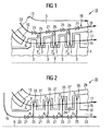
- FIG. 1 shows a high-temperature steam turbine 10 according to a particularly preferred embodiment. It can with a working medium in the form of a main flow 17 with parameters for pressure p, z. B. at 250 bar and a temperature above 540 ° C, or z. B. according to the "Neft" article, are applied.
- the steam turbine 10 has a rotor 1 with a number of rotor or rotor blades attached thereto, which are arranged in so-called blade rows 3 in a row.
- the blade rows 3 are rotatable in a housing 5, which has a number of stator blade rows 7 and thereby extends along an axial extent along an axis 9, ie in the longitudinal direction.
- the rotatable blade rows 3 engage like fingers in spaces between the stationary vane rows. 7
- housing 5 is designed as a particularly preferred embodiment of a steam turbine body according to the concept of the invention.
- the housing 5 could also be designed as an inner housing or as a guide blade carrier and / or be formed in the manner of a segmented construction of a number of housing segments.
- the housing 5 has an inner wall 11 and an outer wall 13. With the inner wall, the housing 5 defines a flow channel 15, which is provided for receiving a main flow 17 of a fluid working medium with a flow pressure.
- the housing 5 has a cooling channel system 19, which is open to the flow channel 15 and integrated in the housing 5, for receiving a cooling medium flow with a cooling medium pressure.
- a pressure reduction device 21 is arranged at the position opposite a blade row 3.
- the pressure reducing device 21 is designed to be self-regulating and able to keep the cooling medium pressure p above the flow pressure P along the longitudinal direction 9.
- the cooling medium pressure is characterized by the pressure p 1 > p 2 > p 3 , which decreases as a result of its height.
- the flow pressure is characterized by the decreasing in their sequence pressures P 1 > P 2 > P 3 .
- each self-regulating pressure reduction device 21 is designed such that p 1 > P 1 and p 2 > P 2 and p 3 > P 3 , ie along the longitudinal direction 9 is the cooling medium pressure of the cooling medium flow held above the flow pressure of the main flow 17.
- a ratio of the cooling medium pressure p to the flow pressure P is greater than 1.0 and may be up to 1.5.
- the ratio is greater than 1.1 and can be up to 1.25.
- cooling channel system 19 has a main cooling channel 23 which extends in the longitudinal direction 9 over all blade rows 3, 7.
- the cooling channel system 19 also has per guide blade stage 7 a branch cooling channel 25, which branches off from the main cooling channel 23 and is open towards the flow channel 15.
- FIG. 2 shows another particularly preferred embodiment of a high-temperature steam turbine 20, which is acted upon with steam as the working medium at a pressure above 250 bar and a temperature above 540 ° C or in modifications with steam parameters according to the "Neft" article.
- FIG. 2 are features of the same function with the same reference numerals as in FIG. 1 even though they are specified in the embodiment of the FIG. 2 in contrast to the embodiment of FIG. 1 are executed differently.
- This relates in particular to the cooling channel system 19 with the main cooling channel 23, the branch cooling channels 25 and the pressure reducing devices 21.
- the cooling channel system 19 is according to the embodiment of the FIG. 2 integrated in a rotor 31 as a particular embodiment of a steam turbine body and takes over substantially the same functions as that with respect to the FIG. 1 explained cooling channel system. Accordingly, the conditions explained for the pressures p 1 > p 2 > p 3 and P 1 > P 2 > P 3 also apply, even if the pressures now occur in different places.
- the rotor 31 delimits the flow channel 15 with its outer wall 33.
- the blade rows 35 in contrast to the blade rows 3, are the same FIG. 1 with the cooling channel system 19, and in particular designed with the branch cooling channels 25.
- the guide blade rows 27 of the housing 29 have no cooling channels.
- each pressure p is a corresponding temperature t and each pressure p is assigned a corresponding temperature T. Also for the temperatures t 1 > t 2 > t 3 and T 1 > T 2 > T 3 .
- the steam turbine casing is designed as a particularly preferred embodiment of a steam turbine body and in the embodiment of the FIG. 2 only the steam turbine rotor is designed as a particularly preferred embodiment of the steam turbine body, so in yet another embodiment not shown here, a high-temperature steam turbine, a steam turbine housing and a steam turbine rotor alike a cooling duct system 19, as it is in the 1 and 2 is shown.
- FIG. 3 shows in detail a steam turbine blade 30, as it can be used as a guide vane in the steam turbine 10 with the housing 5 as a particularly preferred embodiment of a steam turbine body.
- the detail drawing of a steam turbine blade 30 shown here is essentially also capable of a rotor blade 31 as a particularly preferred embodiment a steam turbine body of the steam turbine 20 of the FIG. 2 represent.
- the blade 30 has a blade root 37, an airfoil 39 and a blade head 41.
- the blade head 41 is presently designed in the form of a cover plate.
- the cooling channel system 19 is presently shown outside of its main cooling channel 23 only with its branch cooling channel 25.
- the branch cooling channel has a branch channel 43 which opens into an annular channel 45, wherein the annular channel 45 surrounds a row of blades whose part is the blade 30.
- a plurality of main cooling channels 23 may be arranged, of which then advantageously each a branch channel 43 or more branch channels 43 branch off to the annular channel 45. The latter are thus part of a branch cooling channel 25.
- the arrangement is preferably symmetrical to the longitudinal direction 9 in order to distribute thermal expansions evenly in the steam turbine body.
- the annular channel 45 is formed directly below the blade root 37.
- the annular channel 45 continues in the form of a blade channel 47 first into the blade root 37 and then into the blade 39.
- the blade channel 47 has an opening 49 which opens the cooling channel system 19 to the flow channel 15.
- the opening 49 opens into an area in the immediate vicinity of a head 41 of the blade 30.
- the cooling channel system 19 and the branch cooling channel 25 is thus via the branch channel 43, the annular channel 45, the blade channel 47 and the opening 49 in the region 51 to the flow channel 15th open.
- the embodiment of the FIG. 3 a guide vane, wherein the region 51 is formed in the form of a sealing region, which forms a seal 53 for sealing the blade head 41 against a rotor 55.
- the hatched area 57 represents the housing. Cooling location is thus a shaft seal.
- the hatched area 57 would represent the rotor and the non-hatched area 55 would represent the housing.
- Self-regulating pressure reducing means 21 have the particular advantage that they, in particular without external intervention, can automatically adjust to the different cooling requirements in different load cases of a steam turbine, ie in particular at full load, partial load or low load.
- a circuit arrangement of a number of self-regulating pressure reduction devices 21 in the cooling channel system 19 can be arranged such that a cooling medium flow depends on the operating state of a steam turbine 10, 20 in the cooling channel system 19 in a direction along or opposite the main flow 17 is umlagerbar.
- exemplary circuit types are in the FIGS. 7 and 8 explained.
- FIG. 4 shows a first example of a pressure reduction device 60 of the type described above.
- the detail shows the pressure reduction device 60 in a cooling channel 61, which may be a main cooling channel 23 or a branch cooling channel 25 of a cooling channel system 19 and which is designated in this case by the reference numeral 61.
- the pressure reduction device 60 in the form of a ball valve is formed by a ball 63, a seating area 65 for the ball 63 and a spring 67 to bias the ball against the force applied by a coolant flow 69.
- the spring 67 is supported against a threaded ring 71, wherein the threaded ring 71 is screwed into the cooling channel 61.
- an optional opening 73 is provided which, even if the ball 63 is firmly seated in the seating area, allows a minimum flow rate of the cooling medium 69 through the ball valve 60.
- the opening 73 thus defines a minimum cross section for the cooling channel 61 in the region of the pressure reduction device 60.
- a pressure p 1 prevails in the cooling channel 61 in front of the seat region 65 of the ball 63.
- the pressure reducing device 60 functions in such a manner that the ball 63 opens as soon as a certain pressure drop ⁇ p is exceeded.
- This specific pressure drop ⁇ p can be preset by the spring force of the spring 67 and the design of the cross section of the cooling channel 61 in the area of the pressure reducing device 60 designed as a ball valve. Decisive are essentially the opening cross section 75 and the circular ring cross section 78 between the ball and the boring wall and the opening cross section 77 of the cooling channel 61.
- a free minimum cross section which is defined by the opening 73 in the seating area 65 of the ball 63.
- the Seating area is advantageously hard-coated or otherwise armored, which increases the durability of seating area 65.
- FIG. 5 shows a functioning according to the same principle pressure reducing device 70 in the form of a closing ball valve 83, the symbol is shown in the detailed representation.
- the presetting of the pressure reduction device with respect to the pressure drop ⁇ p takes place taking into account the spring force of the spring 67 and the opening cross section 77, the circular ring section 78 between the ball and the bore and the opening cross section 79 of the cooling channel 61.
- the detail also shows a rest position 64 of the ball 63.
- the Resting position 64 the cooling channel 61 is opened in the region of relatively large overflow openings 74.
- the ball 63 is moved from its rest position 64 in its position shown in the detailed representation against the force of the spring 67, wherein the spring 67 is compressed.
- the pressure reducing device 70 is closed except for the minimum cross section 73. For this reason, the in FIG. 5 shown pressure reducing device 70 referred to as closing ball valve 83.
- FIG. 6 shows a detailed view of a pressure reducing device 80 in a cooling channel system 19.
- the illustrated cooling channel system is formed by one or a number of main cooling channels 23, one or a plurality of branch cooling channels 25 and one or a plurality of branch cooling channels 25 and one or a number of annular channels 45.
- the branch cooling channel 25 is formed by a branch channel 43 and by the annular channel 45.
- the annular channel continues into a blade channel 47, which in the present case has a blade root 37 and an airfoil 39, similar to FIG FIG. 3 shown, interspersed. Except for cooling a blade, the cooling channel system 19 can also serve to cool other suitable cooling locations.
- a number of pressure reducing devices are each arranged in the form of a differential pressure-loaded slide 85, which is mounted displaceably in a seating area 66 against a spring 68.
- the area of the pressure reducing device 80 is open through an opening 87 to the flow channel 15, wherein the flow channel 15, the main flow 17 leads. Therefore countered by each of the cooling medium pressures p 1> p 2> p 3 flow pressures P 1> P 2> P3.
- On the slider 85 thus acts on a pressure difference, which is formed by P 1 on the one hand and p 1 and p 2 on the other.
- a spring 68 is biased on the left side of the detailed representation such that the slide 85 closes the main cooling channel 23 against the coolant flow 69.
- the pressures p in the cooling channel system can be increased such that the pressure reduction device 60 opens in the left part of the detailed representation, while a pressure reduction device 80 remains closed in the right part of the detailed representation.
- cooling medium can be relocated a cooling medium flow 69 depending on the operating state of a steam turbine 10, 20 in the cooling channel system 19 in a direction along the main flow 17.
- this principle of action can also cooling medium of a cooling medium flow 69 depending on the operating condition of a Steam turbine 10, 20 are rearranged in the cooling channel system 19 in a direction opposite to the main flow 17.
- FIG. 7 shows an exemplary first type of circuit 90 of closing ball valves 83 in a coolant flow 69, which is guided in a cooling channel system 19 with a main cooling channel 23 and a branch cooling channel 25.
- the closing ball valves 83 close to a predetermined minimum cross-section after in FIG. 5 explained principle when a certain pressure difference is achieved.
- This behavior can be advantageously used in the partial load range, if an increased cooling steam mass flow 69 is required downstream of a main flow 17. In the partial load range, this is the case when, with a small pressure drop occurring in a main flow 17, a smaller cooling takes place in the course of the expansion of a working medium.
- FIG. 8 shows a second type of circuit 100 of closing ball valves 83 in a cooling passage system 19 having a main cooling passage 23 and a branch cooling passage 25.
- the closing ball valves 83 are each arranged in a branch cooling channel 25.
- the cooling channel system 19 carries a coolant flow 69.
- any throttle device 89 may be provided in the main cooling passage 23 in the present embodiment.
- the closing ball valves 83 when a certain pressure difference ⁇ p or a certain volume flow of the cooling medium 69 in the cooling channel system 19, in particular in a branch cooling channel 25 is exceeded, except for a minimum cross-section after in FIG. 5 explained principle.
- This type of second circuit 100 has the advantage that in a part-load or low-load operation of a steam turbine 10, 20 downstream of a main flow 17, an increased cooling steam mass flow 69 can be provided.
- the closing ball valves 83 then close in the front region of a main flow, while they remain open in the rear region of the main flow 17, so that an increased cooling steam mass flow 69 is provided downstream in the partial load region.
- the closing behavior is determined in particular by the pressure differences between the cooling medium flow 69 and main flow 17.
- FIGS. 7 and 8 shown circuits result from the regulation of the cooling medium pressure p in the part-load and low load range.
- a cooling medium pressure of the cooling medium 69 is readjusted to the pressure in the main flow 17.
- the cooling medium pressure of a cooling medium flow 69 remains substantially constant.
- a steam turbine body for example in the form of a housing 5 or a rotor 31 delimits along a longitudinal direction 9 a flow channel 15 which is provided for receiving a main flow 17 of a fluid working medium with a flow pressure P, P 1 > P 2 > P 3 .
- the body usually carries a number of blade rows 7, 35, which have a plurality of blades and are arranged one behind the other in the longitudinal direction 9, each extending into the flow channel 15.
- the body has a cooling channel system 19, which is open to the flow channel 15 and integrated in the body, for receiving a cooling medium flow with a cooling medium pressure p, p 1 > p 2 > p 3 .
- the presented concept provides that in the cooling channel system 19 at least one flow resistance in the form of a pressure reduction device 21, 60, 70, 80 is arranged, which is self-regulating and is designed along the Longitudinal 9 the cooling medium pressure p, p 1 > p 2 > p 3 above the flow pressure P, P 1 > P 2 > P 3 to keep.
Landscapes
- Engineering & Computer Science (AREA)
- Mechanical Engineering (AREA)
- General Engineering & Computer Science (AREA)
- Turbine Rotor Nozzle Sealing (AREA)
Claims (14)
- Corps ( 5, 31 ) de turbine à vapeur,
qui délimite suivant une direction ( 9 ) longitudinale , un canal ( 15 ) d'écoulement prévu pour la réception d'un courant ( 17 ) principal d'un milieu de travail fluide ayant une pression ( P, P1>P2>P3 ) d'écoulement, et
qui a un système ( 19 ) de canalisation de refroidissement ouvert vers le canal ( 15 ) d'écoulement pour la réception d'un courant de milieu de refroidissement ayant une pression de milieu de refroidissement,
dans lequel il est disposé dans le système ( 19 ) de canalisation de refroidissement au moins une résistance à l'écoulement sous la forme d'un dispositif ( 21, 60, 70, 80 ) de diminution de la pression, qui se règle de soi-même et qui est conçu pour maintenir dans la direction longitudinale la pression ( p, p1>p2>p3 ) du milieu de refroidissement au dessus de la pression ( P, P1>P2>P3 ) d'écoulement,
caractérisé en ce que
le système ( 19 ) de canalisation de refroidissement a un canal ( 23 ) de refroidissement principal qui s'étend dans la direction ( 9 ) longitudinale sur une étendue d'au moins une rangée ( 7, 35 ) d'aubes, et
qui a un canal ( 25 ) de refroidissement de dérivation qui bifurque du canal ( 23 ) de refroidissement principal et qui est ouvert vers le canal ( 15 ) d'écoulement,
le dispositif ( 21 ) de diminution de la pression étant monté dans le canal ( 23 ) de refroidissement principal et/ou dans le canal ( 25 ) de refroidissement de dérivation. - Corps de turbine à vapeur suivant la revendication 1,
caractérisé en ce que
le corps porte un certain nombre de rangées ( 7, 35 ) d'aubes qui ont plusieurs aubes ( 30 ), qui sont disposées les unes derrières les autres dans la direction ( 9 ) longitudinale et qui s'étendent respectivement dans le canal d'écoulement, et
le canal ( 25 ) de refroidissement de dérivation comporte un canal ( 45 ) annulaire entourant une rangée ( 7, 35 ) d'aubes. - Corps de turbine à vapeur suivant la revendication 1 ou 2,
caractérisé en ce que
le canal ( 25 ) de refroidissement de dérivation comporte un ou plusieurs canaux ( 47 ) d'aube, qui partent du canal ( 45 ) annulaire et qui mènent dans un certain nombre ou dans toutes les aubes ( 30 ) d'une rangée ( 7, 35 ) d'aubes. - Corps de turbine à vapeur suivant l'une des revendications 1 à 3,
caractérisé en ce que
le système ( 19 ) de canalisation de refroidissement est dans une grande mesure symétrique autour d'un axe ( 9 ) central. - Corps de turbine à vapeur suivant l'une des revendications 1 à 4 sous la forme d'un rotor ( 31 ) de turbine à vapeur.
- Corps de turbine à vapeur suivant la revendication 5,
caractérisé en ce que
le système ( 19 ) de canalisation de refroidissement a une ouverture ( 49 ) qui débouche dans une zone ( 51 ) entre une tête ( 41 ) d'une aube ( 30 ) mobile et un carter ( 55 ) de turbine à vapeur. - Corps de turbine à vapeur suivant l'une des revendications 1 à 4 sous la forme d'un carter ( 5 ) de turbine à vapeur.
- Corps de turbine à vapeur suivant la revendication 7,
caractérisé en ce que
le système ( 19 ) de canalisation de refroidissement à une ouverture ( 49 ) qui débouche dans une zone ( 51 ) d'étanchéité entre une tête ( 41 ) d'une aube ( 30 ) directrice et un rotor ( 55 ) de turbine à vapeur. - Corps de turbine à vapeur suivant l'une des revendications 1 à 8,
caractérisé en ce que
le dispositif ( 21 ) de diminution de la pression est sous la forme d'un robinet ( 60, 70 ) à bille chargée par un ressort à l'encontre du courant du milieu de refroidissement. - Corps de turbine à vapeur suivant l'une des revendications 1 à 8,
caractérisé en ce que
le dispositif ( 21 ) de diminution de la pression est sous la forme d'un tiroir ( 80 ) précontraint. - Corps de turbine à vapeur suivant l'une des revendications 1 à 10,
caractérisé en ce que
un certain nombre de dispositifs ( 21, 60, 70, 80 ) de diminution de la pression se réglant d'eux même est mis dans le système ( 19 ) de canalisation de refroidissement, en ce que du milieu de refroidissement d'un courant ( 69 ) de milieu de refroidissement peut, en fonction de l'état de fonctionnement d'une turbine ( 10, 20 ) à vapeur, passer dans le système ( 19 ) de canalisation de refroidissement dans le sens du courant ( 17 ) principal ou dans le sens contraire. - Turbine ( 10, 20 ) à vapeur, notamment de turbine à vapeur à haute température, ayant un corps de turbine à vapeur suivant l'une des revendications précédentes.
- Procédé de refroidissement d'une turbine ( 10, 20 ) à vapeur suivant la revendication 12, dans lequel- le canal ( 15 ) d'écoulement est alimenté en un courant ( 17 ) principal d'un milieu de travail fluide ayant une pression d'écoulement,- un système ( 19 ) de canalisation de refroidissement est alimenté en un courant de milieu de refroidissement ayant une pression de milieu de refroidissement,caractérisé en ce que- dans la direction ( 9 ) longitudinale du système ( 19 ) de canalisation de refroidissement, on maintient la pression ( p, p1>p2>p3 ) du milieu de refroidissement, par au moins une résistance à l'écoulement sous la forme d'un dispositif ( 21, 60, 70, 80 ) de diminution de la pression se réglant de soi-même, au dessus de la pression ( P, P1>P2>P3 ) d'écoulement.
- Utilisation d'un dispositif ( 21, 60, 70, 80 ) de diminution de la pression se réglant de soi-même comme résistance à l'écoulement dans le système ( 19 ) de canalisation de refroidissement d'une turbine ( 10, 20 ) à vapeur suivant la revendication 12 pour maintenir, lors du fonctionnement de la turbine ( 10, 20 ) à vapeur, le long de la direction ( 9 ) longitudinale, la pression ( p, p1>p2>p3 ) du milieu de refroidissement avec réglage de soi-même au dessus de la pression ( P, P1>P2>P3 ) d'écoulement.
Priority Applications (1)
| Application Number | Priority Date | Filing Date | Title |
|---|---|---|---|
| EP04012136A EP1598537B1 (fr) | 2004-05-21 | 2004-05-21 | Corps d'une turbine à vapeur et procédé de refroidissement d'une turbine à vapeur |
Applications Claiming Priority (1)
| Application Number | Priority Date | Filing Date | Title |
|---|---|---|---|
| EP04012136A EP1598537B1 (fr) | 2004-05-21 | 2004-05-21 | Corps d'une turbine à vapeur et procédé de refroidissement d'une turbine à vapeur |
Publications (2)
| Publication Number | Publication Date |
|---|---|
| EP1598537A1 EP1598537A1 (fr) | 2005-11-23 |
| EP1598537B1 true EP1598537B1 (fr) | 2012-10-03 |
Family
ID=34925083
Family Applications (1)
| Application Number | Title | Priority Date | Filing Date |
|---|---|---|---|
| EP04012136A Expired - Lifetime EP1598537B1 (fr) | 2004-05-21 | 2004-05-21 | Corps d'une turbine à vapeur et procédé de refroidissement d'une turbine à vapeur |
Country Status (1)
| Country | Link |
|---|---|
| EP (1) | EP1598537B1 (fr) |
Families Citing this family (1)
| Publication number | Priority date | Publication date | Assignee | Title |
|---|---|---|---|---|
| EP1905949A1 (fr) * | 2006-09-20 | 2008-04-02 | Siemens Aktiengesellschaft | Refroidissement d'un élément d'une turbine à vapeur |
Family Cites Families (3)
| Publication number | Priority date | Publication date | Assignee | Title |
|---|---|---|---|---|
| US2297853A (en) * | 1941-08-07 | 1942-10-06 | Westinghouse Electric & Mfg Co | Heating steam turbine |
| US5358374A (en) * | 1993-07-21 | 1994-10-25 | General Electric Company | Turbine nozzle backflow inhibitor |
| US6443690B1 (en) * | 1999-05-05 | 2002-09-03 | Siemens Westinghouse Power Corporation | Steam cooling system for balance piston of a steam turbine and associated methods |
-
2004
- 2004-05-21 EP EP04012136A patent/EP1598537B1/fr not_active Expired - Lifetime
Also Published As
| Publication number | Publication date |
|---|---|
| EP1598537A1 (fr) | 2005-11-23 |
Similar Documents
| Publication | Publication Date | Title |
|---|---|---|
| DE60203959T2 (de) | Luftgekühltes Abgasgehäuse für eine Gasturbine | |
| EP1131537B1 (fr) | Procede de fonctionnement d'une turbomachine | |
| EP2596213B1 (fr) | Turbine à vapeur avec un refroidissement interne | |
| EP1624155A1 (fr) | Turbine à vapeur et procédé d'opération d'une turbine à vapeur | |
| DE3226052A1 (de) | Deckbandaufbau fuer ein gasturbinentriebwerk | |
| EP1452688A1 (fr) | Rotor pour une turbine à vapeur, procédé et utilisation de refroidissement d'un tel rotor | |
| EP1780376A1 (fr) | Turbine à vapeur | |
| EP2434164A1 (fr) | Traitement de carter variable | |
| EP2455584A1 (fr) | Turbine à gaz avec des moyens de contrôle de refroidisment comprenant partialement des alliages à mémoire de forme | |
| DE102010037862A1 (de) | Wirbelkammern zur Spaltströmungssteuerung | |
| EP2718545B1 (fr) | Turbine à vapeur comprenant un piston de compensation | |
| DE102017110050A1 (de) | Aufgeweitete zentrale Ausnehmung hinter der Flügelprofilvorderkante | |
| WO2014033220A1 (fr) | Procédé de refroidissement permettant de faire fonctionner une turbine à gaz | |
| EP0508067A1 (fr) | Dispositif de réglage de la section d'écoulement dans une turbomachine | |
| EP0984138B1 (fr) | Turbomachine avec arbre refroidie | |
| EP3130748A1 (fr) | Refroidissement de rotor pour une turbine a vapeur | |
| DE102017110055A1 (de) | Zentraler Zwischenkanal, der äußere Wände hinter einem Vorderkantenkanal eines Schaufelblattes überbrückt | |
| WO2017133873A1 (fr) | Turbine à gaz équipée d'un piston à poussée axiale et d'un palier radial | |
| WO2008043663A1 (fr) | Rotor pour une turbomachine | |
| EP3155226B1 (fr) | Turbine à vapeur et procédé de fonctionnement d'une turbine à vapeur | |
| DE102016202833A1 (de) | Gasturbine mit Kühlung über die hintere Hohlwelle | |
| DE10303340A1 (de) | Kühleinrichtung | |
| EP1598537B1 (fr) | Corps d'une turbine à vapeur et procédé de refroidissement d'une turbine à vapeur | |
| EP1445427A1 (fr) | Turbine à vapeur et procédé d'opération d'une turbine à vapeur | |
| EP2598724B1 (fr) | Turbine à vapeur et procédé pour refroidir une turbine à vapeur |
Legal Events
| Date | Code | Title | Description |
|---|---|---|---|
| PUAI | Public reference made under article 153(3) epc to a published international application that has entered the european phase |
Free format text: ORIGINAL CODE: 0009012 |
|
| AK | Designated contracting states |
Kind code of ref document: A1 Designated state(s): AT BE BG CH CY CZ DE DK EE ES FI FR GB GR HU IE IT LI LU MC NL PL PT RO SE SI SK TR |
|
| AX | Request for extension of the european patent |
Extension state: AL HR LT LV MK |
|
| 17P | Request for examination filed |
Effective date: 20051219 |
|
| AKX | Designation fees paid |
Designated state(s): CH DE GB IT LI |
|
| GRAP | Despatch of communication of intention to grant a patent |
Free format text: ORIGINAL CODE: EPIDOSNIGR1 |
|
| GRAS | Grant fee paid |
Free format text: ORIGINAL CODE: EPIDOSNIGR3 |
|
| GRAA | (expected) grant |
Free format text: ORIGINAL CODE: 0009210 |
|
| AK | Designated contracting states |
Kind code of ref document: B1 Designated state(s): CH DE GB IT LI |
|
| REG | Reference to a national code |
Ref country code: GB Ref legal event code: FG4D Free format text: NOT ENGLISH |
|
| REG | Reference to a national code |
Ref country code: CH Ref legal event code: EP |
|
| REG | Reference to a national code |
Ref country code: CH Ref legal event code: NV Representative=s name: SIEMENS SCHWEIZ AG, CH |
|
| REG | Reference to a national code |
Ref country code: DE Ref legal event code: R096 Ref document number: 502004013785 Country of ref document: DE Effective date: 20121129 |
|
| RAP2 | Party data changed (patent owner data changed or rights of a patent transferred) |
Owner name: SIEMENS AKTIENGESELLSCHAFT |
|
| PLBE | No opposition filed within time limit |
Free format text: ORIGINAL CODE: 0009261 |
|
| STAA | Information on the status of an ep patent application or granted ep patent |
Free format text: STATUS: NO OPPOSITION FILED WITHIN TIME LIMIT |
|
| 26N | No opposition filed |
Effective date: 20130704 |
|
| REG | Reference to a national code |
Ref country code: DE Ref legal event code: R097 Ref document number: 502004013785 Country of ref document: DE Effective date: 20130704 |
|
| PGFP | Annual fee paid to national office [announced via postgrant information from national office to epo] |
Ref country code: GB Payment date: 20160512 Year of fee payment: 13 |
|
| PGFP | Annual fee paid to national office [announced via postgrant information from national office to epo] |
Ref country code: IT Payment date: 20160527 Year of fee payment: 13 |
|
| PGFP | Annual fee paid to national office [announced via postgrant information from national office to epo] |
Ref country code: DE Payment date: 20160720 Year of fee payment: 13 Ref country code: CH Payment date: 20160802 Year of fee payment: 13 |
|
| REG | Reference to a national code |
Ref country code: CH Ref legal event code: PCOW Free format text: NEW ADDRESS: WERNER-VON-SIEMENS-STRASSE 1, 80333 MUENCHEN (DE) |
|
| REG | Reference to a national code |
Ref country code: DE Ref legal event code: R119 Ref document number: 502004013785 Country of ref document: DE |
|
| REG | Reference to a national code |
Ref country code: CH Ref legal event code: PL |
|
| GBPC | Gb: european patent ceased through non-payment of renewal fee |
Effective date: 20170521 |
|
| PG25 | Lapsed in a contracting state [announced via postgrant information from national office to epo] |
Ref country code: LI Free format text: LAPSE BECAUSE OF NON-PAYMENT OF DUE FEES Effective date: 20170531 Ref country code: CH Free format text: LAPSE BECAUSE OF NON-PAYMENT OF DUE FEES Effective date: 20170531 |
|
| PG25 | Lapsed in a contracting state [announced via postgrant information from national office to epo] |
Ref country code: GB Free format text: LAPSE BECAUSE OF NON-PAYMENT OF DUE FEES Effective date: 20170521 Ref country code: DE Free format text: LAPSE BECAUSE OF NON-PAYMENT OF DUE FEES Effective date: 20171201 |
|
| PG25 | Lapsed in a contracting state [announced via postgrant information from national office to epo] |
Ref country code: IT Free format text: LAPSE BECAUSE OF NON-PAYMENT OF DUE FEES Effective date: 20170521 |