EP1598537A1 - Corps d'une turbine à vapeur et procédé de refroidissement d'une turbine à vapeur - Google Patents
Corps d'une turbine à vapeur et procédé de refroidissement d'une turbine à vapeur Download PDFInfo
- Publication number
- EP1598537A1 EP1598537A1 EP04012136A EP04012136A EP1598537A1 EP 1598537 A1 EP1598537 A1 EP 1598537A1 EP 04012136 A EP04012136 A EP 04012136A EP 04012136 A EP04012136 A EP 04012136A EP 1598537 A1 EP1598537 A1 EP 1598537A1
- Authority
- EP
- European Patent Office
- Prior art keywords
- steam turbine
- cooling
- flow
- pressure
- cooling channel
- Prior art date
- Legal status (The legal status is an assumption and is not a legal conclusion. Google has not performed a legal analysis and makes no representation as to the accuracy of the status listed.)
- Granted
Links
- 238000001816 cooling Methods 0.000 title claims abstract description 183
- 238000000034 method Methods 0.000 title claims description 4
- 239000002826 coolant Substances 0.000 claims abstract description 80
- 230000009467 reduction Effects 0.000 claims description 26
- 239000012530 fluid Substances 0.000 claims description 8
- 238000007789 sealing Methods 0.000 claims description 4
- 230000036961 partial effect Effects 0.000 description 12
- 238000011161 development Methods 0.000 description 7
- 230000018109 developmental process Effects 0.000 description 7
- 238000013461 design Methods 0.000 description 6
- 230000007423 decrease Effects 0.000 description 5
- 230000008901 benefit Effects 0.000 description 4
- 230000035882 stress Effects 0.000 description 4
- 230000000694 effects Effects 0.000 description 3
- 230000017525 heat dissipation Effects 0.000 description 3
- 241001295925 Gegenes Species 0.000 description 2
- PXHVJJICTQNCMI-UHFFFAOYSA-N Nickel Chemical compound [Ni] PXHVJJICTQNCMI-UHFFFAOYSA-N 0.000 description 2
- 239000003638 chemical reducing agent Substances 0.000 description 2
- 230000003247 decreasing effect Effects 0.000 description 2
- 238000010586 diagram Methods 0.000 description 2
- 230000004941 influx Effects 0.000 description 2
- 230000000670 limiting effect Effects 0.000 description 2
- 239000000463 material Substances 0.000 description 2
- 230000008646 thermal stress Effects 0.000 description 2
- 230000009471 action Effects 0.000 description 1
- 230000006978 adaptation Effects 0.000 description 1
- 238000007792 addition Methods 0.000 description 1
- 230000002411 adverse Effects 0.000 description 1
- 229910045601 alloy Inorganic materials 0.000 description 1
- 239000000956 alloy Substances 0.000 description 1
- 238000004873 anchoring Methods 0.000 description 1
- 230000009286 beneficial effect Effects 0.000 description 1
- 230000033228 biological regulation Effects 0.000 description 1
- 230000037237 body shape Effects 0.000 description 1
- 238000010276 construction Methods 0.000 description 1
- 230000001419 dependent effect Effects 0.000 description 1
- 239000002803 fossil fuel Substances 0.000 description 1
- 230000006872 improvement Effects 0.000 description 1
- 230000003993 interaction Effects 0.000 description 1
- 238000012986 modification Methods 0.000 description 1
- 230000004048 modification Effects 0.000 description 1
- 229910052759 nickel Inorganic materials 0.000 description 1
- 238000010248 power generation Methods 0.000 description 1
- 230000001376 precipitating effect Effects 0.000 description 1
- 230000002829 reductive effect Effects 0.000 description 1
- 230000000284 resting effect Effects 0.000 description 1
- 230000000630 rising effect Effects 0.000 description 1
- 239000007787 solid Substances 0.000 description 1
- 238000012549 training Methods 0.000 description 1
- 238000009423 ventilation Methods 0.000 description 1
- XLYOFNOQVPJJNP-UHFFFAOYSA-N water Substances O XLYOFNOQVPJJNP-UHFFFAOYSA-N 0.000 description 1
Images


Classifications
-
- F—MECHANICAL ENGINEERING; LIGHTING; HEATING; WEAPONS; BLASTING
- F01—MACHINES OR ENGINES IN GENERAL; ENGINE PLANTS IN GENERAL; STEAM ENGINES
- F01D—NON-POSITIVE DISPLACEMENT MACHINES OR ENGINES, e.g. STEAM TURBINES
- F01D5/00—Blades; Blade-carrying members; Heating, heat-insulating, cooling or antivibration means on the blades or the members
- F01D5/02—Blade-carrying members, e.g. rotors
- F01D5/08—Heating, heat-insulating or cooling means
-
- F—MECHANICAL ENGINEERING; LIGHTING; HEATING; WEAPONS; BLASTING
- F01—MACHINES OR ENGINES IN GENERAL; ENGINE PLANTS IN GENERAL; STEAM ENGINES
- F01D—NON-POSITIVE DISPLACEMENT MACHINES OR ENGINES, e.g. STEAM TURBINES
- F01D25/00—Component parts, details, or accessories, not provided for in, or of interest apart from, other groups
- F01D25/08—Cooling; Heating; Heat-insulation
- F01D25/12—Cooling
-
- Y—GENERAL TAGGING OF NEW TECHNOLOGICAL DEVELOPMENTS; GENERAL TAGGING OF CROSS-SECTIONAL TECHNOLOGIES SPANNING OVER SEVERAL SECTIONS OF THE IPC; TECHNICAL SUBJECTS COVERED BY FORMER USPC CROSS-REFERENCE ART COLLECTIONS [XRACs] AND DIGESTS
- Y02—TECHNOLOGIES OR APPLICATIONS FOR MITIGATION OR ADAPTATION AGAINST CLIMATE CHANGE
- Y02T—CLIMATE CHANGE MITIGATION TECHNOLOGIES RELATED TO TRANSPORTATION
- Y02T50/00—Aeronautics or air transport
- Y02T50/60—Efficient propulsion technologies, e.g. for aircraft
Definitions
- the invention relates to a steam turbine body, along a longitudinal direction delimits a flow channel, the for receiving a main flow of a fluid working medium is provided with a flow pressure, and the one to Flow channel open cooling channel system for receiving a Has cooling medium flow with a cooling medium pressure.
- the invention further relates to a method for cooling a steam turbine, wherein the flow channel with a main flow a fluid working medium with a flow pressure is applied, and the cooling duct system with a Cooling medium flow is subjected to a cooling medium pressure becomes.
- the invention also relates to a use.
- Every turbine or sub-turbine is understood by one Working medium is flowed through in the form of steam.
- gas turbines with gas and / or air as the working medium flows through, but which is completely different and pressure conditions are subject to steam as one Steam turbine.
- steam turbines z. B. the part of a turbine incoming working fluid with the highest temperature at the same time the highest pressure on.
- An open cooling system with an open to the flow channel Cooling system is in gas turbines without sub-turbine external Supply of cooling medium feasible.
- Steam turbine should be provided an external supply. The state of the art regarding gas turbines can already be so not for the assessment of the present application be used.
- a flow channel limiting steam turbine body may be formed in the form of a rotor or a housing.
- a steam turbine usually includes one with blades occupied rotatably mounted rotor, which within a housing or housing shell is arranged. With flow of the housing shell formed by the interior of the flow channel with heated and pressurized steam is the Rotor turned over the blades by the steam.
- the blades of the rotor are also referred to as blades. These are usually along a blade row the outer periphery is arranged on the outside of the rotor.
- housing casings are usually stationary Guides suspended, which along an axial Expansion of the body into the interspaces of the rotor blades to grab.
- a vane is usually at one first location along an inside of the steam turbine housing held. She is usually part of one Leitschaufelsch comprising a number of vanes, along an inner circumference on the inside of the Steam turbine housing are arranged. Each one points Guide vane with her blade radially inward. A Leitschaufelsch Ltd at said first point along the axial expansion is also called vane grille or wreath marked. Usually, a number of rows of vane connected in series. Accordingly is on a second point along the axial extent behind the first place another second scoop along the Held inside the steam turbine housing. A pair of one Blade row and a vane row will also referred to as a blade stage.
- the housing shell of such a steam turbine can from a Number of housing segments be formed. Under the housing shell the steam turbine is in particular the stationary one Housing component of a steam turbine or a turbine part to understand that along the longitudinal direction of the steam turbine a Interior space in the form of a flow channel, the Flow through the working medium in the form of steam provided is.
- This can, depending on the type of steam turbine, an inner housing and / or a vane carrier. But it can too a turbine housing may be provided which does not have an inner housing or has no vane carrier.
- DE 3421067 C2 discloses an inner housing a steam turbine with a cool, already expanded Steam around.
- this has the disadvantage that a temperature difference over the réellegepatusewandung limited must remain, otherwise at too high a temperature difference thermally deform the inner casing too much would.
- a heat dissipation takes place, however, the heat dissipation takes place relatively far from the place of heat supply.
- a heat dissipation in the immediate vicinity of the heat is not yet has been sufficiently realized.
- Another passive Cooling can be achieved by means of a suitable design of expansion of the working medium in a so-called diagonal stage be achieved. However, this is only one achieve very limited cooling effect for the housing.
- Blade cooling is known from WO 97/08431.
- WO 97/49901 and WO 97/49900 is known a single Guide vane ring for shielding individual rotor areas selectively fed by one of a central cavity separate radial channel in the rotor with a medium to act on.
- the medium via the channel to the working medium admixed and the vane ring selective incident flow.
- the rotor are in increased centrifugal stresses in purchasing to take, which is a significant disadvantage in interpretation and Operation represents.
- EP 1154123 is a possibility of removal and guidance a cooling medium from other areas of a steam system and the supply of the cooling medium in the inflow region of Working medium described.
- examples are higher steam parameters for high-temperature steam turbines mentioned in picture 13 of the article.
- the mentioned article is used to improve the cooling of a high-temperature steam turbine casing a cooling steam supply and forwarding of Cooling steam proposed by the first row of vanes. This provides active cooling. This is but limited to the main flow area of the working medium and still in need of improvement.
- Desirable would be a structurally simple and simultaneously efficient active cooling in a steam turbine body of the initially mentioned type.
- the invention begins, whose task it is, a steam turbine body, a steam turbine and a Method of cooling a steam turbine and use specify, in particular, the cooling duct system mechanically advantageous and at the same time in its cooling effect is designed to be efficient and flexible.
- this object is achieved according to the invention solved in that in the cooling channel system at least a flow resistance in the form of a pressure reducing device is arranged, which is self-regulating and designed along the longitudinal direction, the cooling medium pressure above the flow pressure to keep.
- the cooling channels advantageously comparatively close to the surface of the inner surface led the housing shell. That is the knowledge underlying that, especially at the lead comparatively hot flow medium in the flow channel the thermal Stress on a surface of the steam turbine body especially is high.
- a particularly needs-based cooling is thus achievable by the respective cooling channel advantageously within a wall of the respective steam turbine body relative to the median plane of the wall towards the Surface, ie to the flow channel limiting surface, offset is positioned.
- the cooling passage system is in the steam turbine body integrated.
- the cooling channel system for example formed by cavities and / or channels in the body itself be.
- the cooling channel system can also by shielding or elements and the body itself formed be by the shielding plates or elements spaced from the Body attached to the body and a cooling duct system in Shape of the channels formed by the spacing and cavities is formed.
- a Flow resistance in the form of a pressure reducing device arranged which is designed in this case self-regulating. It So this is a device that is from a merely described in EP 03002472.3 and EP 03002471.5 Bore is designed differently and goes beyond this because it also has a flexible functionality, while a mere throttle bore is geometrically tight is.
- a self-regulating pressure reducing device In the present case, a device is understood to mean the pressure as a result of an interplay between a force and a Counterforce regulates. The force is applied to the pressure reducing device in this case by the cooling medium flow and / or the Main flow of the working medium introduced.
- the counterforce can preferably in the form of a bias of the pressure reducing device be preset.
- a presetting may depend on the positioning of the pressure reducing device different from one position along the longitudinal direction, as well as the cooling medium pressure along the longitudinal direction decreases in the cooling channel system - similar to the flow pressure the working medium along the longitudinal direction of the steam turbine body decreases.
- So is such a bias on the input side especially high and lower on the output side it is thus decreasing along the longitudinal direction To preset dimensions.
- Pressure reduction devices can along the longitudinal direction to keep the cooling medium pressure above the flow pressure.
- the pressure reduction device in the form of a preferably biased against the cooling medium flow Trainee.
- the slider can in particular differential pressure be.
- the differential pressure can be advantageously formed by cooling medium flow and main flow be.
- the Cooling channel system has a main cooling channel, which in Longitudinal direction over an extension of at least one blade row extends, and that the cooling channel system a branch cooling channel has, which branches off from the main cooling channel and the Flow channel is open.
- a pressure reduction device can also in a Branch cooling channel can be arranged.
- a pressure reduction device may be provided.
- a pressure reducer could be over it also between two branch cooling channels in the main cooling channel be arranged.
- the body has a number of, having a plurality of blades, in the longitudinal direction one behind the other arranged rows of blades carrying, each one extend into the flow channel and wherein the branch cooling channel a ring channel surrounding a blade row.
- a trickle channel of a Lead the main cooling duct to an annular channel.
- Such a ring channel is preferably at the position of one blade row Blade row provided, in particular directly below the anchoring of a blade root of a blade of the blade row.
- an annular channel runs inside the rotor a blade row.
- the branch cooling channel has one or more of An annular channel outgoing blade channels, which in one, a number or all blades of a blade stage lead.
- a cooling medium is parallel for the expansion of a main flow gradually through specifically restricted facilities as well as individual or several blade rows and / or blade stages supplied for cooling a respective blade.
- the cooling medium can preferably be in the form of steam or some Applications possibly also in the form of water from external side be supplied to the cooling channel system.
- the cooling medium passes through hollow bored or hollow-cast blades advantageous in an area above the blade head.
- the cooling medium can also emerge at a point of the steam turbine body, at the no blade row is arranged. It is advantageous Any suitable surface to be cooled coolable. For example is thereby a sealing area between one Steam turbine body and a blade row coolable.
- the cooling duct system proposed here can be mechanical advantageous and at the same time designed to be efficient and flexible be as firmly given constructive and geometric Measures for throttling the cooling medium are avoided. Instead, according to the presented concept, a number used by self-regulating pressure reducing devices.
- the cooling channel system in particular the mentioned main cooling channels, Sting cooling channels and blade cooling channels, in particular in relation to the annular cooling channel, preferable.
- the pressure reduction devices of the cooling duct system better in their function to the requirements of the different ones Adjust cooling requirements at partial loads.
- Such an adaptation would be merely constructive and thus with fixed geometry predetermined cooling channel system not possible.
- the steam turbine 10 has a rotor 1 with a number attached rotor or rotor blades, arranged in so-called blade rows 3 in a row are.
- the blade rows 3 are rotatable in one Housing 5, which has a number of rows of vane 7 and thereby along an axial extension along a Axle 9, that extends in the longitudinal direction.
- the rotatable blade rows 3 grip like fingers in spaces between the stationary vane rows 7.
- the housing 5 shown in FIG. 1 is considered to be a special one preferred embodiment of a steam turbine body according to executed the concept of the invention.
- the housing 5 could also as an inner case or as a vane carrier be formed and / or in the manner of a segmented design be formed by a number of housing segments.
- the housing 5 has an inner wall 11 and an outer wall 13 on. With the inner wall, the housing 5 defines a Flow channel 15, which receives a main flow 17 a fluid working fluid provided with a flow pressure is.
- the arranged one behind the other in the longitudinal direction Guide vane rows 7 each extend into the flow channel 15.
- the housing 5 has a flow channel 15th open in the housing 5 integrated cooling channel system 19 for receiving a cooling medium flow with a cooling medium pressure. In the cooling channel system 19 is on the one blade row 3 opposite position each have a pressure reducing device 21 arranged.
- the pressure reducing device 21 is self-regulating and capable of running along the Longitudinal 9 the cooling medium pressure p above the flow pressure P to
- the cooling medium pressure is characterized by the pressure p 1 > p 2 > p 3 , which decreases as a result of its height.
- the flow pressure is characterized by the decreasing in their sequence pressures P 1 > P 2 > P 3 .
- each self-regulating pressure reduction device 21 is designed such that p 1 > P 1 and p 2 > P 2 and p 3 > P 3 , ie along the longitudinal direction 9 the cooling medium pressure of the cooling medium flow is maintained above the flow pressure of the main flow 17.
- a ratio of the cooling medium pressure p to the flow pressure P is greater than 1.0 and may be up to 1.5.
- the ratio is greater than 1.1 and can be up to 1.25.
- the cooling channel system 19 shown in FIG 1 has a Main cooling channel 23, which extends in the longitudinal direction 9 over all Blade rows 3, 7 extends. Incidentally, the cooling channel system 19 per Leitschaufelissue 7 a branch cooling channel 25, which branches off from the main cooling channel 23 and the flow channel 15 is open.
- FIG. 2 shows a further particularly preferred embodiment a high-temperature steam turbine 20, with steam as the working medium at a pressure above 250 bar and a Temperature above 540 ° C is applied or in modifications with steam parameters according to the "Neft" article.
- FIG 2 features of the same function with the same Named as in FIG 1, even if they are in detail in the embodiment of FIG 2 in contrast to the embodiment 1 are executed differently.
- This in particular concerns the cooling channel system 19 with the main cooling channel 23, the branch cooling channels 25 and the pressure reducing means 21st
- the cooling channel system 19 is integrated in a rotor 31 as a special embodiment of a steam turbine body and essentially assumes the same functions as the cooling channel system explained with reference to FIG. Accordingly, the conditions explained for the pressures p 1 > p 2 > p 3 and P 1 > P 2 > P 3 also apply, even if the pressures now occur at different locations.
- the rotor 31 is limited by its outer wall 33 the flow channel 15.
- this time are the blade rows 35 in contrast to the blade rows 3 of the 1 with the cooling channel system 19, and in particular with the branch cooling channels 25 designed.
- the vane rows 27th of the housing 29 no cooling channels.
- each pressure p is a corresponding temperature t and each pressure p is assigned a corresponding temperature T. Also for the temperatures t 1 > t 2 > t 3 and T 1 > T 2 > T 3 .
- FIG. 3 shows in detail a steam turbine blade 30, as a guide vane on the steam turbine 10 with the housing 5 as a particularly preferred embodiment a steam turbine body can be used.
- the detailed drawing shown here is a Steam turbine blade 30 essentially also a blade in a rotor 31 as a particularly preferred embodiment a steam turbine body of the steam turbine 20 of the FIG 2 represent.
- the blade 30 has a blade root 37, an airfoil 39 and a blade head 41.
- the blade head 41 is in the present case in the form of a cover plate.
- the cooling duct system 19 is present outside of its main cooling channel 23 shown only with its branch cooling channel 25.
- the branch cooling channel has a branch passage 43 which is in an annular channel 45 opens, wherein the annular channel 45 a row of blades, whose part is the blade 30 surrounds.
- the blade row can be arranged a plurality of main cooling channels 23 be, of which then advantageous each a stitch channel 43 or more branch channels 43 branch off to the annular channel 45. The latter are thus part of a branch cooling channel 25.
- the arrangement is preferably symmetrical to the longitudinal direction 9 to thermal expansions in the steam turbine body evenly to distribute.
- the annular channel 45 is directly below the blade root 37th educated.
- the annular channel 45 is in the form of a blade channel 47 first in the blade foot 37 and then in the Blade sheet 39 continues. It can, depending on the application, one, several or all blades 30 of a blade stage one here have shown blade channel 47.
- the blade channel 47 has an opening 49 which the cooling channel system 19 for Flow channel 15 opens.
- the opening 49 opens into a Area in the immediate vicinity of a head 41 of the blade 30.
- the cooling channel system 19 and the branch cooling channel 25 is thus on the branch channel 43, the annular channel 45, the blade channel 47 and the opening 49 in the region 51 to the flow channel 15 open.
- FIG 3 shows a Guide vane, wherein the region 51 in the form of a sealing region is formed, which is a seal 53 for sealing the Blade head 41 against a rotor 55 forms.
- the hatched area 57 represents the housing So it is a shaft seal. This will create a shield of the adjacent to the region 51 component, present this is the rotor 55, reached.
- the hatched area 57 would be the rotor represent and the non-hatched area 55 the housing.
- Self-regulating pressure reducing devices 21 have the particular advantage that they, in particular without an intervention from the outside, focusing on the different ones Cooling requirements for different load cases Steam turbine, ie in particular at full load, partial load or Low load, can set automatically.
- Cooling requirements advantageous.
- the temperature decreases a main flow 17 namely in the course of expansion of a working medium.
- partial load or low load there is a lower temperature drop in particular due to ventilation. That is, should the inlet temperature remain the same at part load or light load a wider range in the Compared to full load to be cooled.
- a circuit arrangement of a number can be used self-regulating pressure reducing means 21 in the cooling channel system Arrange 19 such that a cooling medium flow dependent from the operating state of a steam turbine 10, 20 in the Cooling channel system 19 in a direction along or opposite the main flow 17 is umlagerbar.
- exemplary Circuit types are explained in FIGS. 7 and 8.
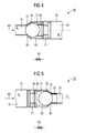
- FIG. 4 shows a first example of a pressure reduction device 60 of the type described above.
- the detailed illustration shows the pressure reduction device 60 in a cooling channel 61, which may be a main cooling channel 23 or a branch cooling channel 25 of a cooling channel system 19 and which is designated in this case by the reference numeral 61.
- the pressure reduction device 60 in the form of a ball valve is formed by a ball 63, a seating area 65 for the ball 63 and a spring 67 to bias the ball against the force applied by a coolant flow 69.
- the spring 67 is supported against a threaded ring 71, wherein the threaded ring 71 is screwed into the cooling channel 61.
- an optional opening 73 is provided which, even if the ball 63 is firmly seated in the seating area, allows a minimum flow rate of the cooling medium 69 through the ball valve 60.
- the opening 73 thus defines a minimum cross section for the cooling channel 61 in the region of the pressure reduction device 60.
- a pressure p 1 prevails in the cooling channel 61 in front of the seat region 65 of the ball 63.
- the pressure reducing device 60 functions in such a manner that the ball 63 opens as soon as a certain pressure drop ⁇ p is exceeded.
- This specific pressure drop ⁇ p can be preset by the spring force of the spring 67 and the design of the cross section of the cooling channel 61 in the area of the pressure reducing device 60 designed as a ball valve. Decisive are essentially the opening cross section 75 and the circular ring cross section 78 between the ball and the boring wall and the opening cross section 77 of the cooling channel 61.
- a free minimum cross section which is defined by the opening 73 in the seating area 65 of the ball 63.
- the seating area is advantageously hard coated or otherwise armored, which increases the durability of the seating area 65.
- FIG 5 shows a functioning according to the same principle pressure reducing device 70 in the form of a closing ball valve 83, the symbol is shown in the detailed representation.
- the same reference numerals have been used for parts of the same function of the pressure reducing device 60 of FIG 4 and the pressure reducing device 70 of FIG.
- the presetting of the pressure reduction device with respect to the pressure drop ⁇ p takes place taking into account the spring force of the spring 67 and the opening cross section 77, the circular ring section 78 between the ball and the bore and the opening cross section 79 of the cooling channel 61.
- the detail also shows a rest position 64 of the ball 63.
- the Resting position 64 the cooling channel 61 is opened in the region of relatively large overflow openings 74.
- the ball 63 is moved from its rest position 64 in its position shown in the detailed representation against the force of the spring 67, wherein the spring 67 is compressed.
- the pressure reducing device 70 is closed except for the minimum cross section 73.
- the pressure reducing device 70 shown in FIG. 5 is referred to as a closing ball valve 83.
- FIG. 6 shows a detailed representation of a pressure reducing device 80 in a cooling channel system 19.
- the latter in the 1 to 3 explained cooling duct system is by one or a number of main cooling channels 23, one or a number of branch cooling channels 25 and one or a plurality of branch cooling channels 25 and one or a number of annular channels 45 educated.
- the branch cooling channel 25 is through a Stichkanal 43 and formed by the annular channel 45.
- the ring channel continues into a blade channel 47 which is present a blade root 37 and an airfoil 39, similar as shown in FIG 3, interspersed. Except for cooling one Shovel can the cooling duct system 19 also for cooling others serve suitable cooling locations.
- a number of pressure reducing devices are each arranged in the form of a differential pressure-loaded slide 85, which is mounted displaceably in a seating area 66 against a spring 68.
- the area of the pressure reducing device 80 is open through an opening 87 to the flow channel 15, wherein the flow channel 15, the main flow 17 leads.
- p 1> p 2> p 3 flow pressures P 1> P 2> P 3 are opposite the cooling medium pressures.
- On the slider 85 thus acts on a pressure difference, which is formed by P 1 on the one hand and p 1 and p 2 on the other.
- a spring 68 is biased on the left side of the detailed representation such that the slide 85 closes the main cooling channel 23 against the coolant flow 69.
- cooling medium of a cooling medium flow 69 can also be redistributed in the direction opposite to the main flow 17, depending on the operating state of a steam turbine 10, 20 in the cooling channel system 19.
- FIG 7 shows an exemplary first type of circuit 90 of FIG closing ball valves 83 in a coolant flow 69, in a cooling channel system 19 with a main cooling channel 23rd and a branch cooling channel 25 is guided.
- the closing ball valves 83 close to a predetermined Minimum cross-section according explained in FIG 5 Principle when a certain pressure difference is reached.
- This behavior can be advantageously used in the partial load range be when downstream of a main flow 17 is an elevated Cooling steam mass flow 69 is required. In the partial load range this is the case, if at a smaller precipitating pressure drop in a main flow 17 a less cooling during the expansion of a working medium he follows.
- FIG. 8 shows a second type of circuit 100 of closing Ball valves 83 in a cooling channel system 19, the one Main cooling channel 23 and a branch cooling channel 25 has.
- the closing ball valves 83 are each in one Branch cooling channel 25 is arranged.
- the cooling channel system 19 leads a coolant flow 69.
- any throttle device 89 be.
- close the closing ball valves 83 if any Pressure difference ⁇ p or a certain volume flow the cooling medium 69 in the cooling channel system 19, in particular in one Branch cooling channel 25 is exceeded, except for a minimum cross section according to the explained in FIG 5 principle.
- These Type of the second circuit 100 has the advantage that in a partial load or low load operation of a steam turbine 10, 20 downstream of a main flow 17 an increased cooling steam mass flow 69 can be provided.
- the area of a main flow then close the closing ball valves 83 while in the rear area the main flow 17 remain open, so that in the partial load range downstream, an increased cooling steam mass flow 69 is provided becomes.
- the closing behavior is in particular also by the pressure differences between cooling medium flow 69 and main flow 17 determined.
- a steam turbine body for example in the form of a housing 5 or a rotor 31 delimits along a longitudinal direction 9 a flow channel 15 which is provided for receiving a main flow 17 of a fluid working medium with a flow pressure P, P 1 > P 2 > P 3 .
- the body usually carries a number of blade rows 7, 35, which have a plurality of blades and are arranged one behind the other in the longitudinal direction 9, each extending into the flow channel 15.
- the body has a cooling channel system 19, which is open to the flow channel 15 and integrated in the body, for receiving a cooling medium flow with a cooling medium pressure p, p 1 > p 2 > p 3 .
- the presented concept provides that in the cooling channel system 19 at least one flow resistance in the form of a pressure reduction device 21, 60, 70, 80 is arranged, which is self-regulating and is designed along the Longitudinal 9 the cooling medium pressure p, p 1 > p 2 > p 3 above the flow pressure P, P 1 > P 2 > P 3 to keep.
Landscapes
- Engineering & Computer Science (AREA)
- Mechanical Engineering (AREA)
- General Engineering & Computer Science (AREA)
- Turbine Rotor Nozzle Sealing (AREA)
Priority Applications (1)
| Application Number | Priority Date | Filing Date | Title |
|---|---|---|---|
| EP04012136A EP1598537B1 (fr) | 2004-05-21 | 2004-05-21 | Corps d'une turbine à vapeur et procédé de refroidissement d'une turbine à vapeur |
Applications Claiming Priority (1)
| Application Number | Priority Date | Filing Date | Title |
|---|---|---|---|
| EP04012136A EP1598537B1 (fr) | 2004-05-21 | 2004-05-21 | Corps d'une turbine à vapeur et procédé de refroidissement d'une turbine à vapeur |
Publications (2)
| Publication Number | Publication Date |
|---|---|
| EP1598537A1 true EP1598537A1 (fr) | 2005-11-23 |
| EP1598537B1 EP1598537B1 (fr) | 2012-10-03 |
Family
ID=34925083
Family Applications (1)
| Application Number | Title | Priority Date | Filing Date |
|---|---|---|---|
| EP04012136A Expired - Lifetime EP1598537B1 (fr) | 2004-05-21 | 2004-05-21 | Corps d'une turbine à vapeur et procédé de refroidissement d'une turbine à vapeur |
Country Status (1)
| Country | Link |
|---|---|
| EP (1) | EP1598537B1 (fr) |
Cited By (1)
| Publication number | Priority date | Publication date | Assignee | Title |
|---|---|---|---|---|
| EP1905949A1 (fr) * | 2006-09-20 | 2008-04-02 | Siemens Aktiengesellschaft | Refroidissement d'un élément d'une turbine à vapeur |
Citations (3)
| Publication number | Priority date | Publication date | Assignee | Title |
|---|---|---|---|---|
| US2297853A (en) * | 1941-08-07 | 1942-10-06 | Westinghouse Electric & Mfg Co | Heating steam turbine |
| US5358374A (en) * | 1993-07-21 | 1994-10-25 | General Electric Company | Turbine nozzle backflow inhibitor |
| EP1050666A2 (fr) * | 1999-05-05 | 2000-11-08 | Siemens Westinghouse Power Corporation | Système de refroidissement à vapeur pour piston d'allègement d'une turbine à vapeur et méthodes associées |
-
2004
- 2004-05-21 EP EP04012136A patent/EP1598537B1/fr not_active Expired - Lifetime
Patent Citations (3)
| Publication number | Priority date | Publication date | Assignee | Title |
|---|---|---|---|---|
| US2297853A (en) * | 1941-08-07 | 1942-10-06 | Westinghouse Electric & Mfg Co | Heating steam turbine |
| US5358374A (en) * | 1993-07-21 | 1994-10-25 | General Electric Company | Turbine nozzle backflow inhibitor |
| EP1050666A2 (fr) * | 1999-05-05 | 2000-11-08 | Siemens Westinghouse Power Corporation | Système de refroidissement à vapeur pour piston d'allègement d'une turbine à vapeur et méthodes associées |
Cited By (1)
| Publication number | Priority date | Publication date | Assignee | Title |
|---|---|---|---|---|
| EP1905949A1 (fr) * | 2006-09-20 | 2008-04-02 | Siemens Aktiengesellschaft | Refroidissement d'un élément d'une turbine à vapeur |
Also Published As
| Publication number | Publication date |
|---|---|
| EP1598537B1 (fr) | 2012-10-03 |
Similar Documents
| Publication | Publication Date | Title |
|---|---|---|
| EP1774140B1 (fr) | Turbine a vapeur et procede pour faire fonctionner une turbine a vapeur | |
| DE60203959T2 (de) | Luftgekühltes Abgasgehäuse für eine Gasturbine | |
| EP1945911B1 (fr) | Turbine à gaz | |
| EP1452688A1 (fr) | Rotor pour une turbine à vapeur, procédé et utilisation de refroidissement d'un tel rotor | |
| DE112009004299T5 (de) | Turbinenschaufelanordnung mit einem Dämpfer | |
| DE102012100266A1 (de) | Gekrümmte Kühlkanäle für eine Turbinenkomponente | |
| EP2596213B1 (fr) | Turbine à vapeur avec un refroidissement interne | |
| DE102010037862A1 (de) | Wirbelkammern zur Spaltströmungssteuerung | |
| DE102006027237A1 (de) | Dampfturbine | |
| DE102017110050A1 (de) | Aufgeweitete zentrale Ausnehmung hinter der Flügelprofilvorderkante | |
| EP2718545B1 (fr) | Turbine à vapeur comprenant un piston de compensation | |
| CH694257A5 (de) | Dampfturbine. | |
| DE102017110055A1 (de) | Zentraler Zwischenkanal, der äußere Wände hinter einem Vorderkantenkanal eines Schaufelblattes überbrückt | |
| EP3130748A1 (fr) | Refroidissement de rotor pour une turbine a vapeur | |
| EP1954922A1 (fr) | Turbine a vapeur a entretoises porteuses | |
| WO2008043663A1 (fr) | Rotor pour une turbomachine | |
| DE102015121651A1 (de) | Interne Kühlkanäle in Turbinenschaufeln | |
| EP1446556A1 (fr) | Turbomachine | |
| EP3397843A1 (fr) | Turbine à gaz équipée d'un piston à poussée axiale et d'un palier radial | |
| EP1165942B1 (fr) | Turbomachine avec un systeme d'elements de paroi pouvant etre refroidi et procede de refroidissement d'un systeme d'elements de paroi | |
| EP1445427A1 (fr) | Turbine à vapeur et procédé d'opération d'une turbine à vapeur | |
| DE10303340A1 (de) | Kühleinrichtung | |
| DE102012209549A1 (de) | Kühlmittelüberbrückungsleitung für eine Gasturbine | |
| DE102016202833A1 (de) | Gasturbine mit Kühlung über die hintere Hohlwelle | |
| WO2016026880A1 (fr) | Turbine à vapeur et procédé pour faire fonctionner une turbine à vapeur |
Legal Events
| Date | Code | Title | Description |
|---|---|---|---|
| PUAI | Public reference made under article 153(3) epc to a published international application that has entered the european phase |
Free format text: ORIGINAL CODE: 0009012 |
|
| AK | Designated contracting states |
Kind code of ref document: A1 Designated state(s): AT BE BG CH CY CZ DE DK EE ES FI FR GB GR HU IE IT LI LU MC NL PL PT RO SE SI SK TR |
|
| AX | Request for extension of the european patent |
Extension state: AL HR LT LV MK |
|
| 17P | Request for examination filed |
Effective date: 20051219 |
|
| AKX | Designation fees paid |
Designated state(s): CH DE GB IT LI |
|
| GRAP | Despatch of communication of intention to grant a patent |
Free format text: ORIGINAL CODE: EPIDOSNIGR1 |
|
| GRAS | Grant fee paid |
Free format text: ORIGINAL CODE: EPIDOSNIGR3 |
|
| GRAA | (expected) grant |
Free format text: ORIGINAL CODE: 0009210 |
|
| AK | Designated contracting states |
Kind code of ref document: B1 Designated state(s): CH DE GB IT LI |
|
| REG | Reference to a national code |
Ref country code: GB Ref legal event code: FG4D Free format text: NOT ENGLISH |
|
| REG | Reference to a national code |
Ref country code: CH Ref legal event code: EP |
|
| REG | Reference to a national code |
Ref country code: CH Ref legal event code: NV Representative=s name: SIEMENS SCHWEIZ AG, CH |
|
| REG | Reference to a national code |
Ref country code: DE Ref legal event code: R096 Ref document number: 502004013785 Country of ref document: DE Effective date: 20121129 |
|
| RAP2 | Party data changed (patent owner data changed or rights of a patent transferred) |
Owner name: SIEMENS AKTIENGESELLSCHAFT |
|
| PLBE | No opposition filed within time limit |
Free format text: ORIGINAL CODE: 0009261 |
|
| STAA | Information on the status of an ep patent application or granted ep patent |
Free format text: STATUS: NO OPPOSITION FILED WITHIN TIME LIMIT |
|
| 26N | No opposition filed |
Effective date: 20130704 |
|
| REG | Reference to a national code |
Ref country code: DE Ref legal event code: R097 Ref document number: 502004013785 Country of ref document: DE Effective date: 20130704 |
|
| PGFP | Annual fee paid to national office [announced via postgrant information from national office to epo] |
Ref country code: GB Payment date: 20160512 Year of fee payment: 13 |
|
| PGFP | Annual fee paid to national office [announced via postgrant information from national office to epo] |
Ref country code: IT Payment date: 20160527 Year of fee payment: 13 |
|
| PGFP | Annual fee paid to national office [announced via postgrant information from national office to epo] |
Ref country code: DE Payment date: 20160720 Year of fee payment: 13 Ref country code: CH Payment date: 20160802 Year of fee payment: 13 |
|
| REG | Reference to a national code |
Ref country code: CH Ref legal event code: PCOW Free format text: NEW ADDRESS: WERNER-VON-SIEMENS-STRASSE 1, 80333 MUENCHEN (DE) |
|
| REG | Reference to a national code |
Ref country code: DE Ref legal event code: R119 Ref document number: 502004013785 Country of ref document: DE |
|
| REG | Reference to a national code |
Ref country code: CH Ref legal event code: PL |
|
| GBPC | Gb: european patent ceased through non-payment of renewal fee |
Effective date: 20170521 |
|
| PG25 | Lapsed in a contracting state [announced via postgrant information from national office to epo] |
Ref country code: LI Free format text: LAPSE BECAUSE OF NON-PAYMENT OF DUE FEES Effective date: 20170531 Ref country code: CH Free format text: LAPSE BECAUSE OF NON-PAYMENT OF DUE FEES Effective date: 20170531 |
|
| PG25 | Lapsed in a contracting state [announced via postgrant information from national office to epo] |
Ref country code: GB Free format text: LAPSE BECAUSE OF NON-PAYMENT OF DUE FEES Effective date: 20170521 Ref country code: DE Free format text: LAPSE BECAUSE OF NON-PAYMENT OF DUE FEES Effective date: 20171201 |
|
| PG25 | Lapsed in a contracting state [announced via postgrant information from national office to epo] |
Ref country code: IT Free format text: LAPSE BECAUSE OF NON-PAYMENT OF DUE FEES Effective date: 20170521 |