EP1598537A1 - Steam turbine body and method of cooling a steam turbine - Google Patents
Steam turbine body and method of cooling a steam turbine Download PDFInfo
- Publication number
- EP1598537A1 EP1598537A1 EP04012136A EP04012136A EP1598537A1 EP 1598537 A1 EP1598537 A1 EP 1598537A1 EP 04012136 A EP04012136 A EP 04012136A EP 04012136 A EP04012136 A EP 04012136A EP 1598537 A1 EP1598537 A1 EP 1598537A1
- Authority
- EP
- European Patent Office
- Prior art keywords
- steam turbine
- cooling
- flow
- pressure
- cooling channel
- Prior art date
- Legal status (The legal status is an assumption and is not a legal conclusion. Google has not performed a legal analysis and makes no representation as to the accuracy of the status listed.)
- Granted
Links
Images


Classifications
-
- F—MECHANICAL ENGINEERING; LIGHTING; HEATING; WEAPONS; BLASTING
- F01—MACHINES OR ENGINES IN GENERAL; ENGINE PLANTS IN GENERAL; STEAM ENGINES
- F01D—NON-POSITIVE DISPLACEMENT MACHINES OR ENGINES, e.g. STEAM TURBINES
- F01D5/00—Blades; Blade-carrying members; Heating, heat-insulating, cooling or antivibration means on the blades or the members
- F01D5/02—Blade-carrying members, e.g. rotors
- F01D5/08—Heating, heat-insulating or cooling means
-
- F—MECHANICAL ENGINEERING; LIGHTING; HEATING; WEAPONS; BLASTING
- F01—MACHINES OR ENGINES IN GENERAL; ENGINE PLANTS IN GENERAL; STEAM ENGINES
- F01D—NON-POSITIVE DISPLACEMENT MACHINES OR ENGINES, e.g. STEAM TURBINES
- F01D25/00—Component parts, details, or accessories, not provided for in, or of interest apart from, other groups
- F01D25/08—Cooling; Heating; Heat-insulation
- F01D25/12—Cooling
-
- Y—GENERAL TAGGING OF NEW TECHNOLOGICAL DEVELOPMENTS; GENERAL TAGGING OF CROSS-SECTIONAL TECHNOLOGIES SPANNING OVER SEVERAL SECTIONS OF THE IPC; TECHNICAL SUBJECTS COVERED BY FORMER USPC CROSS-REFERENCE ART COLLECTIONS [XRACs] AND DIGESTS
- Y02—TECHNOLOGIES OR APPLICATIONS FOR MITIGATION OR ADAPTATION AGAINST CLIMATE CHANGE
- Y02T—CLIMATE CHANGE MITIGATION TECHNOLOGIES RELATED TO TRANSPORTATION
- Y02T50/00—Aeronautics or air transport
- Y02T50/60—Efficient propulsion technologies, e.g. for aircraft
Definitions
- the invention relates to a steam turbine body, along a longitudinal direction delimits a flow channel, the for receiving a main flow of a fluid working medium is provided with a flow pressure, and the one to Flow channel open cooling channel system for receiving a Has cooling medium flow with a cooling medium pressure.
- the invention further relates to a method for cooling a steam turbine, wherein the flow channel with a main flow a fluid working medium with a flow pressure is applied, and the cooling duct system with a Cooling medium flow is subjected to a cooling medium pressure becomes.
- the invention also relates to a use.
- Every turbine or sub-turbine is understood by one Working medium is flowed through in the form of steam.
- gas turbines with gas and / or air as the working medium flows through, but which is completely different and pressure conditions are subject to steam as one Steam turbine.
- steam turbines z. B. the part of a turbine incoming working fluid with the highest temperature at the same time the highest pressure on.
- An open cooling system with an open to the flow channel Cooling system is in gas turbines without sub-turbine external Supply of cooling medium feasible.
- Steam turbine should be provided an external supply. The state of the art regarding gas turbines can already be so not for the assessment of the present application be used.
- a flow channel limiting steam turbine body may be formed in the form of a rotor or a housing.
- a steam turbine usually includes one with blades occupied rotatably mounted rotor, which within a housing or housing shell is arranged. With flow of the housing shell formed by the interior of the flow channel with heated and pressurized steam is the Rotor turned over the blades by the steam.
- the blades of the rotor are also referred to as blades. These are usually along a blade row the outer periphery is arranged on the outside of the rotor.
- housing casings are usually stationary Guides suspended, which along an axial Expansion of the body into the interspaces of the rotor blades to grab.
- a vane is usually at one first location along an inside of the steam turbine housing held. She is usually part of one Leitschaufelsch comprising a number of vanes, along an inner circumference on the inside of the Steam turbine housing are arranged. Each one points Guide vane with her blade radially inward. A Leitschaufelsch Ltd at said first point along the axial expansion is also called vane grille or wreath marked. Usually, a number of rows of vane connected in series. Accordingly is on a second point along the axial extent behind the first place another second scoop along the Held inside the steam turbine housing. A pair of one Blade row and a vane row will also referred to as a blade stage.
- the housing shell of such a steam turbine can from a Number of housing segments be formed. Under the housing shell the steam turbine is in particular the stationary one Housing component of a steam turbine or a turbine part to understand that along the longitudinal direction of the steam turbine a Interior space in the form of a flow channel, the Flow through the working medium in the form of steam provided is.
- This can, depending on the type of steam turbine, an inner housing and / or a vane carrier. But it can too a turbine housing may be provided which does not have an inner housing or has no vane carrier.
- DE 3421067 C2 discloses an inner housing a steam turbine with a cool, already expanded Steam around.
- this has the disadvantage that a temperature difference over the réellegepatusewandung limited must remain, otherwise at too high a temperature difference thermally deform the inner casing too much would.
- a heat dissipation takes place, however, the heat dissipation takes place relatively far from the place of heat supply.
- a heat dissipation in the immediate vicinity of the heat is not yet has been sufficiently realized.
- Another passive Cooling can be achieved by means of a suitable design of expansion of the working medium in a so-called diagonal stage be achieved. However, this is only one achieve very limited cooling effect for the housing.
- Blade cooling is known from WO 97/08431.
- WO 97/49901 and WO 97/49900 is known a single Guide vane ring for shielding individual rotor areas selectively fed by one of a central cavity separate radial channel in the rotor with a medium to act on.
- the medium via the channel to the working medium admixed and the vane ring selective incident flow.
- the rotor are in increased centrifugal stresses in purchasing to take, which is a significant disadvantage in interpretation and Operation represents.
- EP 1154123 is a possibility of removal and guidance a cooling medium from other areas of a steam system and the supply of the cooling medium in the inflow region of Working medium described.
- examples are higher steam parameters for high-temperature steam turbines mentioned in picture 13 of the article.
- the mentioned article is used to improve the cooling of a high-temperature steam turbine casing a cooling steam supply and forwarding of Cooling steam proposed by the first row of vanes. This provides active cooling. This is but limited to the main flow area of the working medium and still in need of improvement.
- Desirable would be a structurally simple and simultaneously efficient active cooling in a steam turbine body of the initially mentioned type.
- the invention begins, whose task it is, a steam turbine body, a steam turbine and a Method of cooling a steam turbine and use specify, in particular, the cooling duct system mechanically advantageous and at the same time in its cooling effect is designed to be efficient and flexible.
- this object is achieved according to the invention solved in that in the cooling channel system at least a flow resistance in the form of a pressure reducing device is arranged, which is self-regulating and designed along the longitudinal direction, the cooling medium pressure above the flow pressure to keep.
- the cooling channels advantageously comparatively close to the surface of the inner surface led the housing shell. That is the knowledge underlying that, especially at the lead comparatively hot flow medium in the flow channel the thermal Stress on a surface of the steam turbine body especially is high.
- a particularly needs-based cooling is thus achievable by the respective cooling channel advantageously within a wall of the respective steam turbine body relative to the median plane of the wall towards the Surface, ie to the flow channel limiting surface, offset is positioned.
- the cooling passage system is in the steam turbine body integrated.
- the cooling channel system for example formed by cavities and / or channels in the body itself be.
- the cooling channel system can also by shielding or elements and the body itself formed be by the shielding plates or elements spaced from the Body attached to the body and a cooling duct system in Shape of the channels formed by the spacing and cavities is formed.
- a Flow resistance in the form of a pressure reducing device arranged which is designed in this case self-regulating. It So this is a device that is from a merely described in EP 03002472.3 and EP 03002471.5 Bore is designed differently and goes beyond this because it also has a flexible functionality, while a mere throttle bore is geometrically tight is.
- a self-regulating pressure reducing device In the present case, a device is understood to mean the pressure as a result of an interplay between a force and a Counterforce regulates. The force is applied to the pressure reducing device in this case by the cooling medium flow and / or the Main flow of the working medium introduced.
- the counterforce can preferably in the form of a bias of the pressure reducing device be preset.
- a presetting may depend on the positioning of the pressure reducing device different from one position along the longitudinal direction, as well as the cooling medium pressure along the longitudinal direction decreases in the cooling channel system - similar to the flow pressure the working medium along the longitudinal direction of the steam turbine body decreases.
- So is such a bias on the input side especially high and lower on the output side it is thus decreasing along the longitudinal direction To preset dimensions.
- Pressure reduction devices can along the longitudinal direction to keep the cooling medium pressure above the flow pressure.
- the pressure reduction device in the form of a preferably biased against the cooling medium flow Trainee.
- the slider can in particular differential pressure be.
- the differential pressure can be advantageously formed by cooling medium flow and main flow be.
- the Cooling channel system has a main cooling channel, which in Longitudinal direction over an extension of at least one blade row extends, and that the cooling channel system a branch cooling channel has, which branches off from the main cooling channel and the Flow channel is open.
- a pressure reduction device can also in a Branch cooling channel can be arranged.
- a pressure reduction device may be provided.
- a pressure reducer could be over it also between two branch cooling channels in the main cooling channel be arranged.
- the body has a number of, having a plurality of blades, in the longitudinal direction one behind the other arranged rows of blades carrying, each one extend into the flow channel and wherein the branch cooling channel a ring channel surrounding a blade row.
- a trickle channel of a Lead the main cooling duct to an annular channel.
- Such a ring channel is preferably at the position of one blade row Blade row provided, in particular directly below the anchoring of a blade root of a blade of the blade row.
- an annular channel runs inside the rotor a blade row.
- the branch cooling channel has one or more of An annular channel outgoing blade channels, which in one, a number or all blades of a blade stage lead.
- a cooling medium is parallel for the expansion of a main flow gradually through specifically restricted facilities as well as individual or several blade rows and / or blade stages supplied for cooling a respective blade.
- the cooling medium can preferably be in the form of steam or some Applications possibly also in the form of water from external side be supplied to the cooling channel system.
- the cooling medium passes through hollow bored or hollow-cast blades advantageous in an area above the blade head.
- the cooling medium can also emerge at a point of the steam turbine body, at the no blade row is arranged. It is advantageous Any suitable surface to be cooled coolable. For example is thereby a sealing area between one Steam turbine body and a blade row coolable.
- the cooling duct system proposed here can be mechanical advantageous and at the same time designed to be efficient and flexible be as firmly given constructive and geometric Measures for throttling the cooling medium are avoided. Instead, according to the presented concept, a number used by self-regulating pressure reducing devices.
- the cooling channel system in particular the mentioned main cooling channels, Sting cooling channels and blade cooling channels, in particular in relation to the annular cooling channel, preferable.
- the pressure reduction devices of the cooling duct system better in their function to the requirements of the different ones Adjust cooling requirements at partial loads.
- Such an adaptation would be merely constructive and thus with fixed geometry predetermined cooling channel system not possible.
- the steam turbine 10 has a rotor 1 with a number attached rotor or rotor blades, arranged in so-called blade rows 3 in a row are.
- the blade rows 3 are rotatable in one Housing 5, which has a number of rows of vane 7 and thereby along an axial extension along a Axle 9, that extends in the longitudinal direction.
- the rotatable blade rows 3 grip like fingers in spaces between the stationary vane rows 7.
- the housing 5 shown in FIG. 1 is considered to be a special one preferred embodiment of a steam turbine body according to executed the concept of the invention.
- the housing 5 could also as an inner case or as a vane carrier be formed and / or in the manner of a segmented design be formed by a number of housing segments.
- the housing 5 has an inner wall 11 and an outer wall 13 on. With the inner wall, the housing 5 defines a Flow channel 15, which receives a main flow 17 a fluid working fluid provided with a flow pressure is.
- the arranged one behind the other in the longitudinal direction Guide vane rows 7 each extend into the flow channel 15.
- the housing 5 has a flow channel 15th open in the housing 5 integrated cooling channel system 19 for receiving a cooling medium flow with a cooling medium pressure. In the cooling channel system 19 is on the one blade row 3 opposite position each have a pressure reducing device 21 arranged.
- the pressure reducing device 21 is self-regulating and capable of running along the Longitudinal 9 the cooling medium pressure p above the flow pressure P to
- the cooling medium pressure is characterized by the pressure p 1 > p 2 > p 3 , which decreases as a result of its height.
- the flow pressure is characterized by the decreasing in their sequence pressures P 1 > P 2 > P 3 .
- each self-regulating pressure reduction device 21 is designed such that p 1 > P 1 and p 2 > P 2 and p 3 > P 3 , ie along the longitudinal direction 9 the cooling medium pressure of the cooling medium flow is maintained above the flow pressure of the main flow 17.
- a ratio of the cooling medium pressure p to the flow pressure P is greater than 1.0 and may be up to 1.5.
- the ratio is greater than 1.1 and can be up to 1.25.
- the cooling channel system 19 shown in FIG 1 has a Main cooling channel 23, which extends in the longitudinal direction 9 over all Blade rows 3, 7 extends. Incidentally, the cooling channel system 19 per Leitschaufelissue 7 a branch cooling channel 25, which branches off from the main cooling channel 23 and the flow channel 15 is open.
- FIG. 2 shows a further particularly preferred embodiment a high-temperature steam turbine 20, with steam as the working medium at a pressure above 250 bar and a Temperature above 540 ° C is applied or in modifications with steam parameters according to the "Neft" article.
- FIG 2 features of the same function with the same Named as in FIG 1, even if they are in detail in the embodiment of FIG 2 in contrast to the embodiment 1 are executed differently.
- This in particular concerns the cooling channel system 19 with the main cooling channel 23, the branch cooling channels 25 and the pressure reducing means 21st
- the cooling channel system 19 is integrated in a rotor 31 as a special embodiment of a steam turbine body and essentially assumes the same functions as the cooling channel system explained with reference to FIG. Accordingly, the conditions explained for the pressures p 1 > p 2 > p 3 and P 1 > P 2 > P 3 also apply, even if the pressures now occur at different locations.
- the rotor 31 is limited by its outer wall 33 the flow channel 15.
- this time are the blade rows 35 in contrast to the blade rows 3 of the 1 with the cooling channel system 19, and in particular with the branch cooling channels 25 designed.
- the vane rows 27th of the housing 29 no cooling channels.
- each pressure p is a corresponding temperature t and each pressure p is assigned a corresponding temperature T. Also for the temperatures t 1 > t 2 > t 3 and T 1 > T 2 > T 3 .
- FIG. 3 shows in detail a steam turbine blade 30, as a guide vane on the steam turbine 10 with the housing 5 as a particularly preferred embodiment a steam turbine body can be used.
- the detailed drawing shown here is a Steam turbine blade 30 essentially also a blade in a rotor 31 as a particularly preferred embodiment a steam turbine body of the steam turbine 20 of the FIG 2 represent.
- the blade 30 has a blade root 37, an airfoil 39 and a blade head 41.
- the blade head 41 is in the present case in the form of a cover plate.
- the cooling duct system 19 is present outside of its main cooling channel 23 shown only with its branch cooling channel 25.
- the branch cooling channel has a branch passage 43 which is in an annular channel 45 opens, wherein the annular channel 45 a row of blades, whose part is the blade 30 surrounds.
- the blade row can be arranged a plurality of main cooling channels 23 be, of which then advantageous each a stitch channel 43 or more branch channels 43 branch off to the annular channel 45. The latter are thus part of a branch cooling channel 25.
- the arrangement is preferably symmetrical to the longitudinal direction 9 to thermal expansions in the steam turbine body evenly to distribute.
- the annular channel 45 is directly below the blade root 37th educated.
- the annular channel 45 is in the form of a blade channel 47 first in the blade foot 37 and then in the Blade sheet 39 continues. It can, depending on the application, one, several or all blades 30 of a blade stage one here have shown blade channel 47.
- the blade channel 47 has an opening 49 which the cooling channel system 19 for Flow channel 15 opens.
- the opening 49 opens into a Area in the immediate vicinity of a head 41 of the blade 30.
- the cooling channel system 19 and the branch cooling channel 25 is thus on the branch channel 43, the annular channel 45, the blade channel 47 and the opening 49 in the region 51 to the flow channel 15 open.
- FIG 3 shows a Guide vane, wherein the region 51 in the form of a sealing region is formed, which is a seal 53 for sealing the Blade head 41 against a rotor 55 forms.
- the hatched area 57 represents the housing So it is a shaft seal. This will create a shield of the adjacent to the region 51 component, present this is the rotor 55, reached.
- the hatched area 57 would be the rotor represent and the non-hatched area 55 the housing.
- Self-regulating pressure reducing devices 21 have the particular advantage that they, in particular without an intervention from the outside, focusing on the different ones Cooling requirements for different load cases Steam turbine, ie in particular at full load, partial load or Low load, can set automatically.
- Cooling requirements advantageous.
- the temperature decreases a main flow 17 namely in the course of expansion of a working medium.
- partial load or low load there is a lower temperature drop in particular due to ventilation. That is, should the inlet temperature remain the same at part load or light load a wider range in the Compared to full load to be cooled.
- a circuit arrangement of a number can be used self-regulating pressure reducing means 21 in the cooling channel system Arrange 19 such that a cooling medium flow dependent from the operating state of a steam turbine 10, 20 in the Cooling channel system 19 in a direction along or opposite the main flow 17 is umlagerbar.
- exemplary Circuit types are explained in FIGS. 7 and 8.
- FIG. 4 shows a first example of a pressure reduction device 60 of the type described above.
- the detailed illustration shows the pressure reduction device 60 in a cooling channel 61, which may be a main cooling channel 23 or a branch cooling channel 25 of a cooling channel system 19 and which is designated in this case by the reference numeral 61.
- the pressure reduction device 60 in the form of a ball valve is formed by a ball 63, a seating area 65 for the ball 63 and a spring 67 to bias the ball against the force applied by a coolant flow 69.
- the spring 67 is supported against a threaded ring 71, wherein the threaded ring 71 is screwed into the cooling channel 61.
- an optional opening 73 is provided which, even if the ball 63 is firmly seated in the seating area, allows a minimum flow rate of the cooling medium 69 through the ball valve 60.
- the opening 73 thus defines a minimum cross section for the cooling channel 61 in the region of the pressure reduction device 60.
- a pressure p 1 prevails in the cooling channel 61 in front of the seat region 65 of the ball 63.
- the pressure reducing device 60 functions in such a manner that the ball 63 opens as soon as a certain pressure drop ⁇ p is exceeded.
- This specific pressure drop ⁇ p can be preset by the spring force of the spring 67 and the design of the cross section of the cooling channel 61 in the area of the pressure reducing device 60 designed as a ball valve. Decisive are essentially the opening cross section 75 and the circular ring cross section 78 between the ball and the boring wall and the opening cross section 77 of the cooling channel 61.
- a free minimum cross section which is defined by the opening 73 in the seating area 65 of the ball 63.
- the seating area is advantageously hard coated or otherwise armored, which increases the durability of the seating area 65.
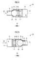
- FIG 5 shows a functioning according to the same principle pressure reducing device 70 in the form of a closing ball valve 83, the symbol is shown in the detailed representation.
- the same reference numerals have been used for parts of the same function of the pressure reducing device 60 of FIG 4 and the pressure reducing device 70 of FIG.
- the presetting of the pressure reduction device with respect to the pressure drop ⁇ p takes place taking into account the spring force of the spring 67 and the opening cross section 77, the circular ring section 78 between the ball and the bore and the opening cross section 79 of the cooling channel 61.
- the detail also shows a rest position 64 of the ball 63.
- the Resting position 64 the cooling channel 61 is opened in the region of relatively large overflow openings 74.
- the ball 63 is moved from its rest position 64 in its position shown in the detailed representation against the force of the spring 67, wherein the spring 67 is compressed.
- the pressure reducing device 70 is closed except for the minimum cross section 73.
- the pressure reducing device 70 shown in FIG. 5 is referred to as a closing ball valve 83.
- FIG. 6 shows a detailed representation of a pressure reducing device 80 in a cooling channel system 19.
- the latter in the 1 to 3 explained cooling duct system is by one or a number of main cooling channels 23, one or a number of branch cooling channels 25 and one or a plurality of branch cooling channels 25 and one or a number of annular channels 45 educated.
- the branch cooling channel 25 is through a Stichkanal 43 and formed by the annular channel 45.
- the ring channel continues into a blade channel 47 which is present a blade root 37 and an airfoil 39, similar as shown in FIG 3, interspersed. Except for cooling one Shovel can the cooling duct system 19 also for cooling others serve suitable cooling locations.
- a number of pressure reducing devices are each arranged in the form of a differential pressure-loaded slide 85, which is mounted displaceably in a seating area 66 against a spring 68.
- the area of the pressure reducing device 80 is open through an opening 87 to the flow channel 15, wherein the flow channel 15, the main flow 17 leads.
- p 1> p 2> p 3 flow pressures P 1> P 2> P 3 are opposite the cooling medium pressures.
- On the slider 85 thus acts on a pressure difference, which is formed by P 1 on the one hand and p 1 and p 2 on the other.
- a spring 68 is biased on the left side of the detailed representation such that the slide 85 closes the main cooling channel 23 against the coolant flow 69.
- cooling medium of a cooling medium flow 69 can also be redistributed in the direction opposite to the main flow 17, depending on the operating state of a steam turbine 10, 20 in the cooling channel system 19.
- FIG 7 shows an exemplary first type of circuit 90 of FIG closing ball valves 83 in a coolant flow 69, in a cooling channel system 19 with a main cooling channel 23rd and a branch cooling channel 25 is guided.
- the closing ball valves 83 close to a predetermined Minimum cross-section according explained in FIG 5 Principle when a certain pressure difference is reached.
- This behavior can be advantageously used in the partial load range be when downstream of a main flow 17 is an elevated Cooling steam mass flow 69 is required. In the partial load range this is the case, if at a smaller precipitating pressure drop in a main flow 17 a less cooling during the expansion of a working medium he follows.
- FIG. 8 shows a second type of circuit 100 of closing Ball valves 83 in a cooling channel system 19, the one Main cooling channel 23 and a branch cooling channel 25 has.
- the closing ball valves 83 are each in one Branch cooling channel 25 is arranged.
- the cooling channel system 19 leads a coolant flow 69.
- any throttle device 89 be.
- close the closing ball valves 83 if any Pressure difference ⁇ p or a certain volume flow the cooling medium 69 in the cooling channel system 19, in particular in one Branch cooling channel 25 is exceeded, except for a minimum cross section according to the explained in FIG 5 principle.
- These Type of the second circuit 100 has the advantage that in a partial load or low load operation of a steam turbine 10, 20 downstream of a main flow 17 an increased cooling steam mass flow 69 can be provided.
- the area of a main flow then close the closing ball valves 83 while in the rear area the main flow 17 remain open, so that in the partial load range downstream, an increased cooling steam mass flow 69 is provided becomes.
- the closing behavior is in particular also by the pressure differences between cooling medium flow 69 and main flow 17 determined.
- a steam turbine body for example in the form of a housing 5 or a rotor 31 delimits along a longitudinal direction 9 a flow channel 15 which is provided for receiving a main flow 17 of a fluid working medium with a flow pressure P, P 1 > P 2 > P 3 .
- the body usually carries a number of blade rows 7, 35, which have a plurality of blades and are arranged one behind the other in the longitudinal direction 9, each extending into the flow channel 15.
- the body has a cooling channel system 19, which is open to the flow channel 15 and integrated in the body, for receiving a cooling medium flow with a cooling medium pressure p, p 1 > p 2 > p 3 .
- the presented concept provides that in the cooling channel system 19 at least one flow resistance in the form of a pressure reduction device 21, 60, 70, 80 is arranged, which is self-regulating and is designed along the Longitudinal 9 the cooling medium pressure p, p 1 > p 2 > p 3 above the flow pressure P, P 1 > P 2 > P 3 to keep.
Abstract
Description
Die Erfindung betrifft einen Dampfturbinen-Körper, der entlang einer Längsrichtung einen Strömungskanal begrenzt, der zur Aufnahme einer Hauptströmung eines fluiden Arbeitsmediums mit einem Strömungsdruck vorgesehen ist, und der ein zum Strömungskanal offenes Kühlkanalsystem zur Aufnahme einer Kühlmediumströmung mit einem Kühlmediumdruck aufweist.The invention relates to a steam turbine body, along a longitudinal direction delimits a flow channel, the for receiving a main flow of a fluid working medium is provided with a flow pressure, and the one to Flow channel open cooling channel system for receiving a Has cooling medium flow with a cooling medium pressure.
Die Erfindung betrifft des Weiteren ein Verfahren zum Kühlen einer Dampfturbine, wobei der Strömungskanal mit einer Hauptströmung eines fluiden Arbeitsmediums mit einem Strömungsdruck beaufschlagt wird, und das Kühlkanalsystem mit einer Kühlmediumströmung mit einem Kühlmediumdruck beaufschlagt wird.The invention further relates to a method for cooling a steam turbine, wherein the flow channel with a main flow a fluid working medium with a flow pressure is applied, and the cooling duct system with a Cooling medium flow is subjected to a cooling medium pressure becomes.
Die Erfindung betrifft auch eine Verwendung.The invention also relates to a use.
Unter einer Dampfturbine im Sinne der vorliegenden Anmeldung wird jede Turbine oder Teilturbine verstanden, die von einem Arbeitsmedium in Form von Dampf durchströmt wird. Im Unterschied dazu werden Gasturbinen mit Gas und/oder Luft als Arbeitsmedium durchströmt, das jedoch völlig anderen Temperatur- und Druckbedingungen unterliegt als der Dampf bei einer Dampfturbine. Im Gegensatz zu Gasturbinen weist bei Dampfturbinen z. B. das einer Teilturbine zuströmende Arbeitsmedium mit der höchsten Temperatur gleichzeitig den höchsten Druck auf. Ein offenes Kühlsystem mit einem zum Strömungskanal offenen Kühlkanalsystem ist bei Gasturbinen auch ohne Teilturbinen-externe Zuführung von Kühlmedium realisierbar. Für eine Dampfturbine sollte eine externe Zuführung vorgesehen sein. Der Stand der Technik betreffend Gasturbinen kann schon deswegen nicht für die Beurteilung des vorliegenden Anmeldungsgegenstands herangezogen werden. Under a steam turbine in the context of the present application Every turbine or sub-turbine is understood by one Working medium is flowed through in the form of steam. In difference These are gas turbines with gas and / or air as the working medium flows through, but which is completely different and pressure conditions are subject to steam as one Steam turbine. Unlike gas turbines has steam turbines z. B. the part of a turbine incoming working fluid with the highest temperature at the same time the highest pressure on. An open cooling system with an open to the flow channel Cooling system is in gas turbines without sub-turbine external Supply of cooling medium feasible. For one Steam turbine should be provided an external supply. The state of the art regarding gas turbines can already be so not for the assessment of the present application be used.
Ein einen Strömungskanal begrenzender Dampfturbinen-Körper kann in Form eines Rotors oder eines Gehäuses gebildet sein. Eine Dampfturbine umfasst üblicherweise einen mit Schaufeln besetzten drehbar gelagerten Rotor, der innerhalb eines Gehäuses bzw. Gehäusemantels angeordnet ist. Bei Durchströmung des vom Gehäusemantel gebildeten Innenraums des Strömungskanals mit erhitztem und unter Druck stehendem Dampf wird der Rotor über die Schaufeln durch den Dampf in Drehung versetzt. Die Schaufeln des Rotors werden auch als Laufschaufeln bezeichnet. Diese sind üblicherweise als Laufschaufelreihe entlang des Außenumfangs an der Außenseite des Rotors angeordnet. Am Gehäusemantel sind darüber hinaus üblicherweise stationäre Leitschaufeln aufgehängt, welche entlang einer axialen Ausdehnung des Körpers in die Zwischenräume der Rotorschaufeln greifen. Eine Leitschaufel ist üblicherweise an einer ersten Stelle entlang einer Innenseite des Dampfturbinen-Gehäuses gehalten. Dabei ist sie üblicherweise Teil einer Leitschaufelreihe, welche eine Anzahl von Leitschaufeln umfasst, die entlang eines Innenumfangs an der Innenseite des Dampfturbinen-Gehäuses angeordnet sind. Dabei weist jede Leitschaufel mit ihrem Schaufelblatt radial nach innen. Eine Leitschaufelreihe an der genannten ersten Stelle entlang der axialen Ausdehnung wird auch als Leitschaufelgitter oder -kranz bezeichnet. Üblicherweise sind eine Anzahl von Leitschaufelreihen hintereinander geschaltet. Entsprechend ist an einer zweiten Stelle entlang der axialen Ausdehnung hinter der ersten Stelle eine weitere zweite Schaufel entlang der Innenseite des Dampfturbinen-Gehäuses gehalten. Ein Paar einer Laufschaufelreihe und einer Leitschaufelreihe wird auch als Schaufelstufe bezeichnet.A flow channel limiting steam turbine body may be formed in the form of a rotor or a housing. A steam turbine usually includes one with blades occupied rotatably mounted rotor, which within a housing or housing shell is arranged. With flow of the housing shell formed by the interior of the flow channel with heated and pressurized steam is the Rotor turned over the blades by the steam. The blades of the rotor are also referred to as blades. These are usually along a blade row the outer periphery is arranged on the outside of the rotor. In addition, housing casings are usually stationary Guides suspended, which along an axial Expansion of the body into the interspaces of the rotor blades to grab. A vane is usually at one first location along an inside of the steam turbine housing held. She is usually part of one Leitschaufelreihe comprising a number of vanes, along an inner circumference on the inside of the Steam turbine housing are arranged. Each one points Guide vane with her blade radially inward. A Leitschaufelreihe at said first point along the axial expansion is also called vane grille or wreath marked. Usually, a number of rows of vane connected in series. Accordingly is on a second point along the axial extent behind the first place another second scoop along the Held inside the steam turbine housing. A pair of one Blade row and a vane row will also referred to as a blade stage.
Der Gehäusemantel einer derartigen Dampfturbine kann aus einer Anzahl von Gehäusesegmenten gebildet sein. Unter dem Gehäusemantel der Dampfturbine ist insbesondere das stationäre Gehäusebauteil einer Dampfturbine oder einer Teilturbine zu verstehen, das entlang der Längsrichtung der Dampfturbine einen Innenraum in Form eines Strömungskanals aufweist, der zur Durchströmung mit dem Arbeitsmedium in Form von Dampf vorgesehen ist. Dies kann, je nach Dampfturbinenart, ein Innengehäuse und/oder ein Leitschaufelträger sein. Es kann aber auch ein Turbinengehäuse vorgesehen sein, welches kein Innengehäuse oder keinen Leitschaufelträger aufweist.The housing shell of such a steam turbine can from a Number of housing segments be formed. Under the housing shell the steam turbine is in particular the stationary one Housing component of a steam turbine or a turbine part to understand that along the longitudinal direction of the steam turbine a Interior space in the form of a flow channel, the Flow through the working medium in the form of steam provided is. This can, depending on the type of steam turbine, an inner housing and / or a vane carrier. But it can too a turbine housing may be provided which does not have an inner housing or has no vane carrier.
Aus Wirkungsgradgründen kann die Auslegung einer derartigen Dampfturbine für so genannte "hohe Dampfparameter", also insbesondere hohe Dampfdrücke und/oder hohe Dampftemperaturen, wünschenswert sein. Allerdings ist insbesondere eine Temperaturerhöhung aus materialtechnischen Gründen nicht unbegrenzt möglich. Um dabei einen sicheren Betrieb der Dampfturbine auch bei besonders hohen Temperaturen zu ermöglichen, kann daher eine Kühlung einzelner Bauteile oder Komponenten wünschenswert sein. Die Bauteile sind nämlich in ihrer Temperaturfestigkeit begrenzt. Ohne effiziente Kühlung würden bei steigenden Temperaturen wesentlich teurere Materialien (z. B. Nickelbasislegierungen) nötig.For efficiency reasons, the interpretation of such Steam turbine for so-called "high steam parameters", ie in particular high vapor pressures and / or high steam temperatures, be desirable. However, in particular, a temperature increase for material-technical reasons not unlimited possible. To ensure safe operation of the steam turbine can also be used at very high temperatures Therefore, cooling of individual components or components desirable be. The components are in fact in their temperature resistance limited. Without efficient cooling would be at rising temperatures significantly more expensive materials (eg. Nickel-based alloys) necessary.
Bei den bisher bekannten Kühlmethoden, insbesondere für einen Dampfturbinen-Körper in Form eines Dampfturbinen-Gehäuses oder eines Rotors, ist zwischen einer aktiven Kühlung und einer passiven Kühlung zu unterscheiden. Bei einer aktiven Kühlung wird eine Kühlung durch ein dem Dampfturbinen-Körper separat, d. h. zusätzlich zum Arbeitsmedium zugeführtes Kühlmedium bewirkt. Dagegen erfolgt eine passive Kühlung lediglich durch eine geeignete Führung oder Verwendung des Arbeitsmediums. Bisher wurden Dampfturbinen-Körper vorzugsweise passiv gekühlt.In the previously known cooling methods, especially for a Steam turbine body in the form of a steam turbine housing or a rotor, is between an active cooling and a to distinguish passive cooling. With active cooling is a cooling by a the steam turbine body separately, d. H. in addition to the working medium supplied cooling medium causes. In contrast, passive cooling only takes place by a suitable guidance or use of the working medium. Heretofore, steam turbine bodies have been preferred passively cooled.
So ist beispielsweise aus der DE 3421067 C2 bekannt, ein Innengehäuse einer Dampfturbine mit kühlem, bereits expandiertem Dampf zu umströmen. Dies hat jedoch den Nachteil, dass eine Temperaturdifferenz über die Innengehäusewandung beschränkt bleiben muss, da sich sonst bei einer zu großen Temperaturdifferenz das Innengehäuse thermisch zu stark verformen würde. Bei einer Umströmung des Innengehäuses findet zwar eine Wärmeabfuhr statt, jedoch erfolgt die Wärmeabfuhr relativ weit entfernt von der Stelle der Wärmezufuhr. Eine Wärmeabfuhr in unmittelbarer Nähe der Wärmezufuhr ist bisher nicht in ausreichendem Maße verwirklicht worden. Eine weitere passive Kühlung kann mittels einer geeigneten Gestaltung der Expansion des Arbeitsmediums in einer so genannten Diagonalstufe erreicht werden. Hierüber lässt sich allerdings nur eine sehr begrenzte Kühlwirkung für das Gehäuse erzielen.For example, DE 3421067 C2 discloses an inner housing a steam turbine with a cool, already expanded Steam around. However, this has the disadvantage that a temperature difference over the Innengehäusewandung limited must remain, otherwise at too high a temperature difference thermally deform the inner casing too much would. In a flow around the inner housing takes place though a heat dissipation takes place, however, the heat dissipation takes place relatively far from the place of heat supply. A heat dissipation in the immediate vicinity of the heat is not yet has been sufficiently realized. Another passive Cooling can be achieved by means of a suitable design of expansion of the working medium in a so-called diagonal stage be achieved. However, this is only one achieve very limited cooling effect for the housing.
Eine Schaufelkühlung ist aus der WO 97/08431 bekannt.Blade cooling is known from WO 97/08431.
In der US 6,102,654 ist eine aktive Kühlung einzelner Komponenten innerhalb eines Dampfturbinen-Gehäuses beschrieben, wobei die Kühlung auf den Einströmbereich des heißen Arbeitsmediums beschränkt ist. Ein Teil des Kühlmediums wird dem Arbeitsmedium beigemischt. Die Kühlung soll dabei durch ein Anströmen der zu kühlenden Komponenten erreicht werden.In US 6,102,654 is an active cooling of individual components described within a steam turbine housing, wherein the cooling to the inflow region of the hot working medium is limited. Part of the cooling medium becomes the working medium added. The cooling should thereby by an influx the components to be cooled are achieved.
Aus der WO 97/49901 und WO 97/49900 ist bekannt, einen einzelnen Leitschaufelkranz zur Abschirmung einzelner Rotorbereiche selektiv durch einen von einem zentralen Hohlraum bespeisten separaten radialen Kanal im Rotor mit einem Medium zu beaufschlagen. Dazu wird das Medium über den Kanal dem Arbeitsmedium beigemischt und der Leitschaufelkranz selektiv angeströmt. Bei der dazu vorgesehenen mittigen Hohlbohrung des Rotors sind jedoch erhöhte Fliehkraftspannungen in Kauf zu nehmen, was einen erheblichen Nachteil in Auslegung und Betrieb darstellt.From WO 97/49901 and WO 97/49900 is known a single Guide vane ring for shielding individual rotor areas selectively fed by one of a central cavity separate radial channel in the rotor with a medium to act on. For this purpose, the medium via the channel to the working medium admixed and the vane ring selective incident flow. At the intended central hollow bore However, the rotor are in increased centrifugal stresses in purchasing to take, which is a significant disadvantage in interpretation and Operation represents.
Aus den Druckschriften WO 01/46576, DE 196 20 828 C1, WO 97/25521 und DE 34 21 067 C2 ist es bekannt, einer Dampfturbine über deren hohl ausgeführten Rotor ein Kühlmedium zuzuführen und dieses im Bereich einzelner Schaufelfüße austreten zu lassen. Auch wird selektiv nur eine bestimmte Stelle des Rotors gekühlt. Weiterhin tritt auch hier eine einen erheblichen Nachteil darstellende große Erhöhung der Fliehkraftspannungen auf.From the documents WO 01/46576, DE 196 20 828 C1, WO 97/25521 and DE 34 21 067 C2 it is known a steam turbine to supply a cooling medium via the hollow rotor and this emerge in the area of individual blade feet allow. Also, only one specific location is selectively selected the rotor cooled. Furthermore, here comes a considerable Disadvantage performing large increase in centrifugal stresses on.
In der EP 1154123 ist eine Möglichkeit der Entnahme und Führung eines Kühlmediums aus anderen Bereichen eines Dampfsystems und die Zuführung des Kühlmediums im Einströmbereich des Arbeitsmediums beschrieben.In EP 1154123 is a possibility of removal and guidance a cooling medium from other areas of a steam system and the supply of the cooling medium in the inflow region of Working medium described.
Zur Erzielung höherer Wirkungsgrade bei der Stromerzeugung
mit fossilen Brennstoffen besteht das Bedürfnis, bei einer
Turbine höhere Dampfparameter, d. h. höhere Drücke und Temperaturen
als bisher üblich anzuwenden. Bei Hochtemperatur-Dampfturbinen
sind beim Dampf als Arbeitsmedium Temperaturen
zum Teil weit über 500 °C, insbesondere über 540 °C, vorgesehen.
Diese Parameter machen eine Hochtemperatur-Dampfturbine
aus. Im Detail sind solche Dampfparameter für Hochtemperatur-Dampfturbinen
in dem Artikel "Neue Dampfturbinenkonzepte für
höhere Eintrittsparameter und längere Endschaufeln" von H. G.
Neft und G. Franconville in der Zeitschrift VGB Kraftwerkstechnik,
Nr. 73 (1993), Heft 5, angegeben. Der Offenbarungsgehalt
des Artikels wird hiermit in die Beschreibung dieser
Anmeldung aufgenommen, um verschiedene Ausführungen einer
Hochtemperatur-Dampfturbine anzugeben. Insbesondere sind Beispiele
höherer Dampfparameter für Hochtemperatur-Dampfturbinen
in Bild 13 des Artikels genannt. In dem genannten Artikel
wird zur Verbesserung der Kühlung eines Hochtemperatur-Dampfturbinen-Gehäuses
eine Kühldampfzufuhr und Weiterleitung des
Kühldampfs durch die erste Leitschaufelreihe vorgeschlagen.
Damit wird zwar eine aktive Kühlung bereitgestellt. Diese ist
jedoch auf den Hauptströmungsbereich des Arbeitsmediums beschränkt
und noch verbesserungswürdig.To achieve higher efficiencies in power generation
There is a need for fossil fuels in a
Turbine higher steam parameters, d. H. higher pressures and temperatures
to apply as usual. For high-temperature steam turbines
are at steam as a working medium temperatures
partly well above 500 ° C, in particular above 540 ° C, provided.
These parameters make a high-temperature steam turbine
out. In detail, such steam parameters are for high temperature steam turbines
in the article "New Steam Turbine Concepts for
higher entry parameters and longer end blades "by H.G.
Neft and G. Franconville in the magazine VGB Kraftwerkstechnik,
No. 73 (1993), No. 5. The revelation content
the article is hereby incorporated into the description of this
Registration was added to various designs of a
Specify high-temperature steam turbine. In particular, examples are
higher steam parameters for high-temperature steam turbines
mentioned in
Alle bisher bekannten Kühlverfahren für ein Dampfturbinen-Gehäuse sehen also, soweit es sich überhaupt um aktive Kühlverfahren handelt, allenfalls ein gezieltes Anströmen eines separaten und zu kühlenden Turbinenteiles vor und sind auf den Einströmbereich des Arbeitsmediums, allenfalls unter Einbeziehung des ersten Leitschaufelkranzes, beschränkt. Dies kann bei einer Belastung üblicher Dampfturbinen mit höheren Dampfparametern zu einer auf die ganze Turbine wirkenden, erhöhten thermischen Belastung führen, welche durch eine oben beschriebene übliche Kühlung des Gehäuses nur unzureichend abgebaut werden könnte. Dampfturbinen, die zur Erzielung höherer Wirkungsgrade grundsätzlich mit höheren Dampfparametern arbeiten, benötigen eine verbesserte Kühlung, insbesondere des Gehäuses und/oder des Rotors, um eine höhere thermische Belastung der Dampfturbine in genügendem Maße abzubauen. Dabei besteht das Problem, dass bei der Nutzung bisher üblicher Turbinenmaterialien die zunehmende Beanspruchung des Dampfturbinen-Körpers durch erhöhte Dampfparameter, z. B. gemäß dem "Neft"-Artikel, zu einer nachteiligen thermischen Belastung des Körpers führen kann, so dass diese technisch nicht mehr ausführbar sind.All previously known cooling method for a steam turbine housing So, as far as it is at all active cooling methods acts, at best, a targeted influx of a separate and to be cooled turbine part before and are on the Inflow area of the working medium, if necessary including of the first vane ring, limited. This can at a load of conventional steam turbines with higher steam parameters to one acting on the whole turbine, increased lead thermal stress, which is described by an above usual cooling of the housing degraded only insufficient could be. Steam turbines that achieve higher Efficiencies basically with higher steam parameters work, require improved cooling, in particular of the housing and / or the rotor to a higher thermal Reduce the load on the steam turbine sufficiently. there there is the problem that in use so far more common Turbine materials the increasing stress of the steam turbine body by increased steam parameters, eg. B. according to the "Neft" article, to an adverse thermal load of the body, so they are not technically are more executable.
In den nicht veröffentlichten europäischen Patentanmeldungen mit dem amtlichen Anmeldeaktenzeichen 03002472.3 und 03002471.5, jeweils mit Zeitrang vom 05. Februar 2003, sind ein aktiv gekühlter Rotor und ein aktiv gekühltes Gehäuse beschrieben, bei dem ein zum Strömungskanal offenes, im Körper integriertes Kühlkanalsystem zur Aufnahme einer Kühlmediumströmung mit einem Kühlmediumdruck vorgesehen ist. In Bezug auf die Figuren 2 der europäischen Anmeldungen wird erläutert, dass in einem Kühlkanalsystem von Schaufelstufe zu Schaufelstufe das Kühlmedium durch Strömungswiderstände gedrosselt werden kann, wobei sich beispielsweise eine Bohrung als Strömungswiderstand eignet. Bei der Drosselung wird der Druck ohne Verrichtung technischer Arbeit reduziert. Diese Art eines Strömungswiderstandes erweist sich aufgrund der fest eingestellten Geometrie einer Bohrung als schlecht anpassbar an unterschiedliche Betriebszustände, z. B. Teillasten.In the unpublished European patent applications with the official registration file 03002472.3 and 03002471.5, each with a seniority of February 05, 2003, are an actively cooled rotor and an actively cooled housing described at the one to the flow channel open, in the body Integrated cooling duct system for receiving a cooling medium flow is provided with a cooling medium pressure. In relation to the figures 2 of the European applications will be explained, that in a cooling duct system from blade stage to Blade stage the cooling medium throttled by flow resistance can be, for example, a hole suitable as flow resistance. When throttling the Pressure reduced without performing technical work. These Type of flow resistance proves due to the fixed geometry of a hole as poorly adaptable to different operating conditions, eg. B. partial loads.
Soweit die übrigen oben genannten Dokumente überhaupt eine aktive Kühlung offenbaren, erweist sich diese im Einzelnen als nicht ausreichend wirkungsvoll und in ihrer mechanischen Konstruktion als nachteilig.As far as the other above-mentioned documents at all one reveal active cooling, this proves in detail as not sufficiently effective and in their mechanical Construction as disadvantageous.
Wünschenswert wäre eine konstruktiv einfache und gleichzeitig effiziente aktive Kühlung bei einem Dampfturbinen-Körper der eingangs genannten Art.Desirable would be a structurally simple and simultaneously efficient active cooling in a steam turbine body of the initially mentioned type.
An dieser Stelle setzt die Erfindung an, deren Aufgabe es ist, einen Dampfturbinen-Körper, eine Dampfturbine und ein Verfahren zur Kühlung einer Dampfturbine sowie eine Verwendung anzugeben, bei der insbesondere das Kühlkanalsystem mechanisch vorteilhaft und gleichzeitig in seiner Kühlwirkung effizient und flexibel ausgelegt ist.At this point, the invention begins, whose task it is, a steam turbine body, a steam turbine and a Method of cooling a steam turbine and use specify, in particular, the cooling duct system mechanically advantageous and at the same time in its cooling effect is designed to be efficient and flexible.
Bezüglich des Dampfturbinen-Körpers wird diese Aufgabe erfindungsgemäß dadurch gelöst, dass im Kühlkanalsystem wenigstens ein Strömungswiderstand in Form einer Druckminderungseinrichtung angeordnet ist, die selbstregelnd ist und ausgelegt ist, entlang der Längsrichtung den Kühlmediumdruck über dem Strömungsdruck zu halten.With respect to the steam turbine body, this object is achieved according to the invention solved in that in the cooling channel system at least a flow resistance in the form of a pressure reducing device is arranged, which is self-regulating and designed along the longitudinal direction, the cooling medium pressure above the flow pressure to keep.
Auf diese Weise wird nämlich garantiert, dass der strömungsnahe Bereich des Dampfturbinen-Körpers ständig mit Kühlmedium beaufschlagt ist. Um dabei eine besonders zuverlässige und bedarfsgerechte Kühlwirkung zu erzielen, sind die Kühlkanäle vorteilhafterweise vergleichsweise oberflächennah an der Innenoberfläche des Gehäusemantels geführt. Dem liegt die Erkenntnis zugrunde, dass gerade bei der Führung vergleichsweise heißen Strömungsmediums im Strömungskanal die thermische Belastung an einer Oberfläche des Dampfturbinen-Körpers besonders hoch ist. Eine besonders bedarfsgerechte Kühlung ist somit erreichbar, indem der jeweilige Kühlkanal vorteilhafterweise innerhalb einer Wand des jeweiligen Dampfturbinen-Körpers relativ zur Mittelebene der Wand in Richtung zur Oberfläche, also zur den Strömungskanal begrenzenden Oberfläche, hin versetzt positioniert ist. In this way, it is guaranteed that the flow close Area of the steam turbine body constantly with cooling medium is charged. To be a particularly reliable and To achieve appropriate cooling effect, are the cooling channels advantageously comparatively close to the surface of the inner surface led the housing shell. That is the knowledge underlying that, especially at the lead comparatively hot flow medium in the flow channel the thermal Stress on a surface of the steam turbine body especially is high. A particularly needs-based cooling is thus achievable by the respective cooling channel advantageously within a wall of the respective steam turbine body relative to the median plane of the wall towards the Surface, ie to the flow channel limiting surface, offset is positioned.
Vorzugsweise ist das Kühlkanalsystem im Dampfturbinen-Körper integriert. Dabei kann das Kühlkanalsystem beispielsweise durch Hohlräume und/oder Kanäle im Körper selbst gebildet sein. Vorzugsweise kann das Kühlkanalsystem auch durch Abschirmbleche oder -elemente und den Körper selbst gebildet sein, indem die Abschirmbleche oder -elemente beabstandet vom Körper am Körper angebracht sind und ein Kühlkanalsystem in Form der durch die Beabstandung gebildeten Kanäle und Hohlräume gebildet ist.Preferably, the cooling passage system is in the steam turbine body integrated. In this case, the cooling channel system, for example formed by cavities and / or channels in the body itself be. Preferably, the cooling channel system can also by shielding or elements and the body itself formed be by the shielding plates or elements spaced from the Body attached to the body and a cooling duct system in Shape of the channels formed by the spacing and cavities is formed.
Gemäß der Erfindung ist in einem solchen Kühlkanalsystem ein Strömungswiderstand in Form einer Druckminderungseinrichtung angeordnet, die vorliegend selbstregelnd ausgelegt ist. Es handelt sich dabei also um eine Einrichtung, die von einer bloßen in der EP 03002472.3 und EP 03002471.5 beschriebenen Bohrung unterschiedlich ausgelegt ist und über diese hinausgeht, da sie zusätzlich eine flexible Funktionalität aufweist, während eine bloße Drosselbohrung geometrisch fest ist. Unter einer selbstregelnden Druckminderungseinrichtung wird vorliegend eine Einrichtung verstanden, die den Druck als Folge eines Wechselspiels zwischen einer Kraft und einer Gegenkraft regelt. Die Kraft wird auf die Druckminderungseinrichtung vorliegend durch die Kühlmediumströmung und/oder die Hauptströmung des Arbeitsmediums eingebracht. Es kann sich also insbesondere um eine von Kühlmediums- und Hauptströmung differenzdruckbeaufschlagte Druckminderungseinrichtung handeln. Außerdem kann auch lediglich von einer Kühlmediumströmung oder Hauptströmung allein druckbeaufschlagte Druckminderungseinrichtung vorgesehen sein. Die Gegenkraft kann vorzugsweise in Form einer Vorspannung der Druckminderungseinrichtung voreingestellt werden. Eine solche Voreinstellung kann je nach Positionierung der Druckminderungseinrichtung an einer Position entlang der Längsrichtung unterschiedlich ausfallen, da auch der Kühlmediumdruck entlang der Längsrichtung im Kühlkanalsystem abnimmt - ähnlich wie auch der Strömungsdruck des Arbeitsmediums entlang der Längsrichtung des Dampfturbinen-Körpers abnimmt. Bei einer Mehrzahl von Druckminderungseinrichtungen ist also eine solche Vorspannung eingangsseitig besonders hoch und ausgangsseitig niedriger einzustellen - sie ist also entlang der Längsrichtung in abnehmendem Maße voreinzustellen.According to the invention is in such a cooling channel system a Flow resistance in the form of a pressure reducing device arranged, which is designed in this case self-regulating. It So this is a device that is from a merely described in EP 03002472.3 and EP 03002471.5 Bore is designed differently and goes beyond this because it also has a flexible functionality, while a mere throttle bore is geometrically tight is. Under a self-regulating pressure reducing device In the present case, a device is understood to mean the pressure as a result of an interplay between a force and a Counterforce regulates. The force is applied to the pressure reducing device in this case by the cooling medium flow and / or the Main flow of the working medium introduced. It may be ie in particular one of Kühlmediums- and main flow act pressure-reducing device acted upon by differential pressure. In addition, only by a cooling medium flow or mainstream alone pressurized pressure reducing device be provided. The counterforce can preferably in the form of a bias of the pressure reducing device be preset. Such a presetting may depend on the positioning of the pressure reducing device different from one position along the longitudinal direction, as well as the cooling medium pressure along the longitudinal direction decreases in the cooling channel system - similar to the flow pressure the working medium along the longitudinal direction of the steam turbine body decreases. In a plurality of pressure reducing devices So is such a bias on the input side especially high and lower on the output side it is thus decreasing along the longitudinal direction To preset dimensions.
Eine auf solche Weise ausgelegte Anzahl von selbstregelnden Druckminderungseinrichtungen vermag entlang der Längsrichtung den Kühlmediumdruck über dem Strömungsdruck zu halten.A number of self-regulating ones designed in this way Pressure reduction devices can along the longitudinal direction to keep the cooling medium pressure above the flow pressure.
Eine solche speziell für die Funktion der Druckminderung ausgestaltete Druckminderungseinrichtung ermöglicht es vorteilhafterweise einen praktisch optimalen Kühlmediumdruck zu erreichen. Gewisse Nachteile, wie sie durch in der EP 03002472.3 und der EP 03002471.5 beschriebene Maßnahmen, wie Bohrungen mit fester Geometrie, zustande kommen, werden vermieden. Insbesondere kann sich die vorliegend beschriebene Druckminderungseinrichtung flexibel auf unterschiedliche Betriebszustände einstellen. Beispielsweise kann bei einer bei Teillast betriebenen Dampfturbine die Temperaturabnahme im Arbeitsmedium im Verlaufe seiner Expansion weniger stark sein als bei einer bei Volllast betriebenen Dampfturbine. Bei Teillast ermöglicht es das hier beschriebene Konzept beispielsweise vergleichsweise mehr Kühlmedium in einen hinteren Teil der Dampfturbine zu verlagern, insbesondere in den hinteren Expansionsbereich des Arbeitsmediums. Damit wird die Hauptkühllast im Teillastbetrieb praktisch in den hinteren Teil der Dampfturbine verlagert. Ebenso kann vergleichsweise mehr Kühlmedium bzw. eine Hauptkühllast vom Anfang auf die Mitte eines Expansionsbereichs eines Arbeitsmediums verlagert werden. Dies wird insbesondere durch die selbstregelnde Auslegung und/oder Anordnung einer Anzahl von Druckminderungseinrichtungen erreicht. Insbesondere sind eine Anzahl von selbstregelnden Druckminderungseinrichtungen im Kühlkanalsystem derart ausgelegt und/oder angeordnet, dass Kühlmedium einer Kühlmediumströmung abhängig vom Betriebszustand einer Dampfturbine in dem Kühlkanalsystem in einer Richtung entlang oder entgegen der Hauptströmung umlagerbar ist. Such specially designed for the function of pressure reduction Pressure reducing device allows advantageously to achieve a practically optimal cooling medium pressure. Certain disadvantages, such as those in the EP 03002472.3 and EP 03002471.5 described measures, how to drill holes with solid geometry avoided. In particular, the presently described Pressure reduction device flexible to different operating conditions to adjust. For example, at a Part load operated steam turbine, the temperature decrease in Working medium in the course of its expansion to be less strong as with a steam turbine operated at full load. at Partial load allows the concept described here, for example comparatively more cooling medium in a rear Part of the steam turbine to relocate, especially in the rear Expansion range of the working medium. This will be the Main cooling load in partial load operation practically in the rear Part of the steam turbine relocated. Similarly, comparatively more cooling medium or a main cooling load from the beginning to the Moved center of an expansion area of a working medium become. This is especially due to the self-regulating design and / or arrangement of a number of pressure reducing devices reached. In particular, a number of self-regulating pressure reducing devices in the cooling duct system designed and / or arranged such that cooling medium of a Cooling medium flow depending on the operating state of a Steam turbine in the cooling duct system in one direction or can be reversed against the main flow.
Vorteilhafte Weiterbildungen der Erfindung sind den Unteransprüchen zu entnehmen und geben im Einzelnen vorteilhafte Möglichkeiten an, das Kühlkanalsystem einerseits und die Druckminderungseinrichtung andererseits, im Rahmen oben erläuterter Aufgabe hinsichtlich weiterer Vorteile zu realisieren.Advantageous developments of the invention are the subclaims to take and give in particular advantageous Possibilities, the cooling duct system on the one hand and the Pressure reducing device on the other hand, in the frame explained above Task to realize further advantages.
Hinsichtlich der Druckminderungseinrichtung erweist es sich als besonders vorteilhaft, diese in Form eines vorzugsweise gegen die Kühlmediumströmung federbelasteten Kugelventils zu bilden.With regard to the pressure reducing device, it proves as particularly advantageous, these in the form of a preferably against the cooling medium flow spring-loaded ball valve to form.
In einer alternativen Ausführungsform erweist es sich als vorteilhaft, die Druckminderungseinrichtung in Form eines vorzugsweise gegen die Kühlmediumströmung vorgespannten Schiebers auszubilden. Der Schieber kann insbesondere differenzdruckbeaufschlagt sein. Der Differenzdruck kann dabei vorteilhaft von Kühlmediumströmung und Hauptströmung gebildet sein.In an alternative embodiment, it turns out to be advantageous, the pressure reduction device in the form of a preferably biased against the cooling medium flow Trainee. The slider can in particular differential pressure be. The differential pressure can be advantageously formed by cooling medium flow and main flow be.
Beide Weiterbildungen sind in Form einer besonders bevorzugten Ausführungsform im Zusammenhang mit der Zeichnung im Detail beschrieben.Both developments are in the form of a particularly preferred Embodiment in connection with the drawing in detail described.
Darüber hinaus hat es sich als vorteilhaft erwiesen, dass das Kühlkanalsystem einen Hauptkühlkanal aufweist, der sich in Längsrichtung über eine Ausdehnung wenigstens einer Schaufelreihe erstreckt, und dass das Kühlkanalsystem einen Zweigkühlkanal aufweist, der vom Hauptkühlkanal abzweigt und zum Strömungskanal offen ist. Auf diese Weise lässt sich nämlich ein besonders effizientes und vorteilhaft gleichzeitig oberflächennahes im Körper integriertes Kühlkanalsystem mit möglichst großer der Körperform angepassten Kühloberfläche realisieren. Eine Druckminderungseinrichtung kann auch in einem Zweigkühlkanal angeordnet sein. Moreover, it has proven to be advantageous that the Cooling channel system has a main cooling channel, which in Longitudinal direction over an extension of at least one blade row extends, and that the cooling channel system a branch cooling channel has, which branches off from the main cooling channel and the Flow channel is open. This is the way to go a particularly efficient and advantageous at the same time near the surface integrated in the body cooling duct system with as possible realize a large body shape adapted Kühloberfläche. A pressure reduction device can also in a Branch cooling channel can be arranged.
Gemäß einer Weiterbildung des so aufgebauten Kühlkanalsystems sind eine oder mehrere Druckminderungseinrichtungen im Hauptkühlkanal angeordnet. Bei jedem Hauptkühlkanal kann beispielsweise für jede Schaufelreihe und/oder Schaufelstufe jeweils eine Druckminderungseinrichtung vorgesehen sein. Gemäß einer besonders vorteilhaften Ausführungsform geht der Zweigkühlkanal von der Druckminderungseinrichtung aus. Alternativ oder zusätzlich könnte eine Druckminderungseinrichtung darüber hinaus auch zwischen zwei Zweigkühlkanälen im Hauptkühlkanal angeordnet sein.According to a development of the thus constructed cooling duct system are one or more pressure reducing devices in the main cooling channel arranged. For example, with each main cooling channel for each row of blades and / or blade level, respectively a pressure reduction device may be provided. According to In a particularly advantageous embodiment of the branch cooling channel from the pressure reducing device. alternative or additionally, a pressure reducer could be over it also between two branch cooling channels in the main cooling channel be arranged.
Gemäß einer Weiterbildung des so aufgebauten Kühlkanalsystems erweist es sich als vorteilhaft, dass der Körper eine Anzahl von, mehrere Schaufeln aufweisende, in Längsrichtung hintereinander angeordnete Schaufelreihen trägt, die sich jeweils in den Strömungskanal erstrecken und wobei der Zweigkühlkanal einen eine Schaufelreihe umgebenden Ringkanal aufweist. Dazu könnte beispielsweise zunächst ein Stichkühlkanal von einem Hauptkühlkanal auf einen Ringkanal führen. Ein solcher Ringkanal ist vorzugsweise pro Schaufelreihe an der Position einer Schaufelreihe vorgesehen, insbesondere direkt unterhalb der Verankerung eines Schaufelfußes einer Schaufel der Schaufelreihe. Insbesondere verläuft ein Ringkanal im Rotor innerhalb einer Laufschaufelreihe. Insbesondere umgibt ein Ringkanal im Gehäuse eine Leitschaufelreihe.According to a development of the thus constructed cooling duct system It proves to be beneficial that the body has a number of, having a plurality of blades, in the longitudinal direction one behind the other arranged rows of blades carrying, each one extend into the flow channel and wherein the branch cooling channel a ring channel surrounding a blade row. To For example, initially a trickle channel of a Lead the main cooling duct to an annular channel. Such a ring channel is preferably at the position of one blade row Blade row provided, in particular directly below the anchoring of a blade root of a blade of the blade row. In particular, an annular channel runs inside the rotor a blade row. In particular, surrounds an annular channel in the housing a row of vanes.
Gemäß noch einer Weiterbildung eines derart aufgebauten Kühlkanalsystems weist der Zweigkühlkanal einen oder mehrere von einem Ringkanal ausgehende Schaufelkanäle auf, die in eine, eine Anzahl oder alle Schaufeln einer Schaufelstufe führen.According to yet another embodiment of a cooling channel system constructed in this way the branch cooling channel has one or more of An annular channel outgoing blade channels, which in one, a number or all blades of a blade stage lead.
Gemäß dieser Weiterbildung wird also ein Kühlmedium parallel zur Expansion einer Hauptströmung schrittweise durch speziell dafür vorgesehene Einrichtungen gedrosselt sowie einzelnen oder mehreren Schaufelreihen und/oder Schaufelstufen zugeführt zur Kühlung einer jeweiligen Schaufel. Das Kühlmedium kann dabei vorzugsweise in Form von Dampf oder bei einigen Anwendungen ggf. auch in Form von Wasser von externer Seite dem Kühlkanalsystem zugeführt werden. Beispielsweise kann Kühlmedium in Form von Dampf dem Dampfkreislauf auf geeignete Weise entnommen werden.According to this development, therefore, a cooling medium is parallel for the expansion of a main flow gradually through specifically restricted facilities as well as individual or several blade rows and / or blade stages supplied for cooling a respective blade. The cooling medium can preferably be in the form of steam or some Applications possibly also in the form of water from external side be supplied to the cooling channel system. For example, can Cooling medium in the form of steam to the steam cycle on suitable Be removed manner.
Gemäß dieser Weiterbildung tritt das Kühlmedium durch hohl gebohrte oder durch hohl gegossene Schaufeln vorteilhaft in einen Bereich oberhalb des Schaufelkopfes. Zusätzlich können weitere Öffnungen in einer Schaufel vorgesehen sein, um einen Kühlmediumsaustritt zu ermöglichen und um damit eine Oberflächenkühlung in Form einer Filmkühlung auf der Schaufeloberfläche bereitzustellen. Insbesondere kann das Kühlmedium auch an einer Stelle des Dampfturbinenkörpers austreten, an der keine Schaufelreihe angeordnet ist. Vorteilhaft ist dabei jede zweckmäßig zu kühlende Bauteiloberfläche kühlbar. Beispielsweise ist dadurch ein Dichtungsbereich zwischen einem Dampfturbinenkörper und einer Schaufelreihe kühlbar.According to this development, the cooling medium passes through hollow bored or hollow-cast blades advantageous in an area above the blade head. In addition, you can be provided in a vane to another openings Cooling medium to allow exit and thus a surface cooling in the form of film cooling on the blade surface provide. In particular, the cooling medium can also emerge at a point of the steam turbine body, at the no blade row is arranged. It is advantageous Any suitable surface to be cooled coolable. For example is thereby a sealing area between one Steam turbine body and a blade row coolable.
Mit dieser Form der Weiterbildung ist eine übermäßige Druckbeanspruchung der besonders zu kühlenden Bauteile in Form der Schaufeln durch ein nicht druckangepasstes Medium vermieden. Gleichzeitig ist ein vorbestimmter, erforderlicher Differenzdruck zur Sicherstellung eines ausreichenden Kühlmassenstroms durch die selbstregelnden Druckminderungseinrichtungen garantiert. Denn das Kühlmedium wird bei dieser Weiterbildung von den Druckminderungseinrichtungen aus in Kühlkanäle geleitet, an die einige oder alle Schaufeln einer Schaufelstufe angeschlossen sind.With this form of training is an excessive pressure stress the particularly cool components in the form of Avoid shoveling by a non-pressure-adjusted medium. At the same time, a predetermined, required differential pressure to ensure a sufficient flow of coolant guaranteed by the self-regulating pressure reducing devices. Because the cooling medium is in this development of directed the pressure reduction devices in cooling channels, connected to some or all blades of a blade stage are.
Dabei kann das hier vorgeschlagene Kühlkanalsystem mechanisch vorteilhaft und gleichzeitig effizient und flexibel ausgebildet sein, da fest vorzugebende konstruktive und geometrische Maßnahmen zur Drosselung des Kühlmediums vermieden sind. Statt dessen wird gemäß dem vorgelegten Konzept eine Anzahl von selbstregelnden Druckminderungseinrichtungen verwendet. In this case, the cooling duct system proposed here can be mechanical advantageous and at the same time designed to be efficient and flexible be as firmly given constructive and geometric Measures for throttling the cooling medium are avoided. Instead, according to the presented concept, a number used by self-regulating pressure reducing devices.
Aus Gründen gleichmäßiger Verformung eines thermisch beanspruchten Dampfturbinen-Körpers ist eine symmetrische Anordnung des Kühlkanalsystem, insbesondere der erwähnten Hauptkühlkanäle, Stichkühlkanäle und Schaufelkühlkanäle, insbesondere in Bezug auf den Ringkühlkanal, vorzuziehen. In dem Fall lassen sich die Druckminderungseinrichtungen des Kühlkanalsystems in ihrer Funktion besser den Erfordernissen der unterschiedlichen Kühlanforderungen bei Teillasten anpassen. Eine solche Anpassung wäre bei einem lediglich konstruktiv und damit mit fester Geometrie vorgegebenen Kühlkanalsystem nicht möglich.For reasons of uniform deformation of a thermally stressed Steam turbine body is a symmetrical arrangement the cooling channel system, in particular the mentioned main cooling channels, Sting cooling channels and blade cooling channels, in particular in relation to the annular cooling channel, preferable. In that case can be the pressure reduction devices of the cooling duct system better in their function to the requirements of the different ones Adjust cooling requirements at partial loads. Such an adaptation would be merely constructive and thus with fixed geometry predetermined cooling channel system not possible.
Ausführungsbeispiele der Erfindung werden nachfolgend anhand der Zeichnung beschrieben. Diese soll die Ausführungsbeispiele nicht maßgeblich darstellen, vielmehr ist die Zeichnung, wo zur Erläuterung dienlich, in schematisierter und/oder leicht verzerrter Form ausgeführt. Im Hinblick auf Ergänzungen der aus der Zeichnung unmittelbar erkennbaren Lehren wird auf den einschlägigen Stand der Technik verwiesen. Im Einzelnen zeigt die Zeichnung in:
- FIG 1
- eine schematisierte Darstellung eines Kühlkanalsystems mit selbstregelnden Druckminderungseinrichtungen bei einem Dampfturbinen-Gehäuse gemäß einer bevorzugten Ausführungsform;
- FIG 2
- eine schematisierte Darstellung eines Kühlkanalsystems mit selbstregelnden Druckminderungseinrichtungen bei einem Dampfturbinen-Rotor gemäß einer bevorzugten Ausführungsform;
- FIG 3
- eine Darstellung einer Zuführung eines Kühlmediums und der Weiterleitung des Kühlmediums in einem im Dampfturbinen-Körper integrierten, oberflächennahen Kühlkanalsystem im Beschaufelungsbereich für eine bevorzugte Ausführungsform eines Dampfturbinen-Gehäuses oder -Rotors;
- FIG 4
- eine Detaildarstellung einer Druckminderungseinrichtung
in Form eines gegen die Kühlmediumströmung
federbelasteten Kugelventils bei einer der besonders
bevorzugten Ausführungsformen der FIG 1
bis 3, wobei das Kugelventil öffnet, wenn ein Grenzdruck überschritten wird; - FIG 5
- eine Detaildarstellung einer Druckminderungseinrichtung
in Form eines gegen die Kühlmediumströmung
federbelasteten Kugelventils bei einer der besonders
bevorzugten Ausführungsformen der FIG 1
bis 3, wobei das Kugelventil schließt, wenn ein Grenzdruck überschritten wird; - FIG 6
- eine Detaildarstellung einer selbstregelnden
Druckminderungseinrichtung in Form eines
differenzdruckbeaufschlagten, vorgespannten Schiebers bei einer
der bevorzugten Ausführungsformen der FIG 1
bis 3; - FIG 7
- ein Diagramm für eine beispielhafte Schaltungsart von Kugelventilen in einem Hauptkühlkanal bei einer der besonders bevorzugten Ausführungsformen der FIG 1 bis FIG 3;
- FIG 8
- ein Diagramm für eine beispielhafte Schaltungsart von Kugelventilen in Nebenkühlkanälen bei einer besonders bevorzugten Ausführungsform der FIG 1 bis FIG 3.
- FIG. 1
- a schematic representation of a cooling duct system with self-regulating pressure reducing means in a steam turbine housing according to a preferred embodiment;
- FIG. 2
- a schematic representation of a cooling duct system with self-regulating pressure reducing means in a steam turbine rotor according to a preferred embodiment;
- FIG. 3
- a representation of a supply of a cooling medium and the forwarding of the cooling medium in a built-in steam turbine body, near-surface cooling channel system in the blading region for a preferred embodiment of a steam turbine housing or rotor;
- FIG. 4
- a detailed view of a pressure reducing device in the form of a spring-loaded against the cooling medium flow ball valve in one of the particularly preferred embodiments of Figures 1 to 3, wherein the ball valve opens when a limit pressure is exceeded;
- FIG. 5
- a detail view of a pressure reducing device in the form of a spring-loaded against the cooling medium flow ball valve in one of the particularly preferred embodiments of Figures 1 to 3, wherein the ball valve closes when a limit pressure is exceeded;
- FIG. 6
- a detailed representation of a self-regulating pressure reducing device in the form of a druckentbeaufschlagten, biased slide in one of the preferred embodiments of Figures 1 to 3;
- FIG. 7
- a diagram of an exemplary type of circuit of ball valves in a main cooling channel in one of the particularly preferred embodiments of FIG 1 to FIG 3;
- FIG. 8
- a diagram for an exemplary circuit type of ball valves in subcooling channels in a particularly preferred embodiment of FIG 1 to FIG. 3
FIG 1 zeigt eine Hochtemperatur-Dampfturbine 10 gemäß einer
besonders bevorzugten Ausführungsform. Sie kann mit einem Arbeitsmedium
in Form einer Hauptströmung 17 mit Parametern für
Druck p, z. B. bei 250 bar und einer Temperatur oberhalb von
540 °C, oder z. B. gemäß dem "Neft"-Artikel, beaufschlagt
werden. Die Dampfturbine 10 weist einen Rotor 1 mit einer Anzahl
von daran angebrachten Rotor- oder Laufschaufeln auf,
die in so genannten Laufschaufelreihen 3 hintereinander angeordnet
sind. Die Laufschaufelreihen 3 sind drehbar in einem
Gehäuse 5, das eine Anzahl von Leitschaufelreihen 7 aufweist
und sich dabei entlang einer axialen Ausdehnung entlang einer
Achse 9, also in Längsrichtung erstreckt. Die drehbaren Laufschaufelreihen
3 greifen dabei wie Finger in Zwischenräume
zwischen die stationären Leitschaufelreihen 7.1 shows a high-
Das in FIG 1 dargestellte Gehäuse 5 ist als eine besonders
bevorzugte Ausführungsform eines Dampfturbinen-Körpers gemäß
dem Konzept der Erfindung ausgeführt. Das Gehäuse 5 könnte
auch als ein Innengehäuse oder als ein Leitschaufelträger
ausgebildet sein und/oder in der Art einer segmentierten Bauweise
von einer Anzahl von Gehäusesegmenten gebildet sein.
Das Gehäuse 5 weist eine Innenwandung 11 und eine Außenwandung
13 auf. Mit der Innenwandung begrenzt das Gehäuse 5 einen
Strömungskanal 15, der zur Aufnahme einer Hauptströmung
17 eines fluiden Arbeitsmediums mit einem Strömungsdruck vorgesehen
ist. Die in Längsrichtung hintereinander angeordneten
Leitschaufelreihen 7 erstrecken sich jeweils in den Strömungskanal
15. Das Gehäuse 5 weist ein zum Strömungskanal 15
offenes im Gehäuse 5 integriertes Kühlkanalsystem 19 zur Aufnahme
einer Kühlmediumströmung mit einem Kühlmediumdruck auf.
In dem Kühlkanalsystem 19 ist an der einer Laufschaufelreihe
3 gegenüberliegenden Position jeweils eine Druckminderungseinrichtung
21 angeordnet. Die Druckminderungseinrichtung 21
ist selbstregelnd ausgelegt und in der Lage entlang der
Längsrichtung 9 den Kühlmediumdruck p über dem Strömungsdruck
P zu halten.The
Der Kühlmediumdruck ist vorliegend durch die in ihrer Höhe
infolge abnehmenden Drücke p1>p2>p3 gekennzeichnet. Ebenso ist
der Strömungsdruck durch die in ihrer Folge abnehmenden Drücke
P1>P2>P3 gekennzeichnet. Im Übrigen ist vorliegend jede
selbstregelnde Druckminderungseinrichtung 21 so ausgelegt,
dass p1>P1 und p2>P2 und p3>P3 gilt, d. h. entlang der Längsrichtung
9 ist der Kühlmediumdruck der Kühlmediumströmung
über dem Strömungsdruck der Hauptströmung 17 gehalten. Ein
Verhältnis des Kühlmediumdrucks p zum Strömungsdruck P ist
größer als 1.0 und kann bis 1.5 betragen. Vorteilhaft ist das
Verhältnis größer als 1.1 und kann bis zu 1.25 betragen.In the present case, the cooling medium pressure is characterized by the pressure p 1 > p 2 > p 3 , which decreases as a result of its height. Likewise, the flow pressure is characterized by the decreasing in their sequence pressures P 1 > P 2 > P 3 . Incidentally, in the present case, each self-regulating
Das in der FIG 1 gezeigte Kühlkanalsystem 19 weist einen
Hauptkühlkanal 23 auf, der sich in Längsrichtung 9 über alle
Schaufelreihen 3, 7 erstreckt. Im Übrigen weist das Kühlkanalsystem
19 auch pro Leitschaufelstufe 7 einen Zweigkühlkanal
25 auf, der vom Hauptkühlkanal 23 abzweigt und zum Strömungskanal
15 hin offen ist.The cooling
Die detaillierte Ausführung des Kühlkanalsystems 19 im Bereich
einer Schaufelstufe 3, 7 wird im Detail in der FIG 3
gezeigt.The detailed design of the cooling
FIG 2 zeigt eine weitere besonders bevorzugte Ausführungsform
einer Hochtemperatur-Dampfturbine 20, die mit Dampf als Arbeitsmedium
bei einem Druck oberhalb von 250 bar und einer
Temperatur oberhalb von 540 °C beaufschlagt wird oder in Abwandlungen
mit Dampfparametern gemäß dem "Neft"-Artikel.2 shows a further particularly preferred embodiment
a high-
In der FIG 2 sind Merkmale gleicher Funktion mit den gleichen
Bezugszeichen wie in FIG 1 benannt, auch wenn sie im Einzelnen
bei der Ausführungsform der FIG 2 im Unterschied zur Ausführungsform
der FIG 1 unterschiedlich ausgeführt sind. Dies
betrifft insbesondere das Kühlkanalsystem 19 mit dem Hauptkühlkanal
23, den Zweigkühlkanälen 25 und den Druckminderungseinrichtungen
21.In FIG 2 features of the same function with the same
Named as in FIG 1, even if they are in detail
in the embodiment of FIG 2 in contrast to the embodiment
1 are executed differently. This
in particular concerns the
Das Kühlkanalsystem 19 ist gemäß der Ausführungsform der
FIG 2 in einem Rotor 31 als besondere Ausführungsform eines
Dampfturbinen-Körpers integriert und übernimmt im Wesentlichen
die gleichen Funktionen wie das in Bezug auf die FIG 1
erläuterte Kühlkanalsystem. Dementsprechend gelten auch die
für die Drücke p1>p2>p3 sowie P1>P2>P3 erläuterten Verhältnisse,
auch wenn die Drücke nunmehr an unterschiedlicher Stelle
auftreten.According to the embodiment of FIG. 2, the cooling
Vorliegend begrenzt der Rotor 31 mit seiner Außenwandung 33
den Strömungskanal 15. Allerdings sind diesmal die Laufschaufelreihen
35 im Unterschied zu den Laufschaufelreihen 3 der
FIG 1 mit dem Kühlkanalsystem 19, und dabei insbesondere mit
den Zweigkühlkanälen 25 ausgelegt. Im Übrigen weisen im Unterschied
zu der FIG 1 vorliegend die Leitschaufelreihen 27
des Gehäuses 29 keine Kühlkanäle auf.In the present case, the
Ähnlich wie die Drücke p und P verhalten sich in der Regel auch die Temperaturen t des Kühlmediums und T des Arbeitsmediums. Das heißt, jedem Druck p ist eine entsprechende Temperatur t und jedem Druck p ist eine entsprechende Temperatur T zugeordnet. Auch für die Temperaturen gilt hier t1>t2>t3 und T1>T2>T3 .Similar to the pressures p and P, the temperatures t of the cooling medium and T of the working medium also generally behave. That is, each pressure p is a corresponding temperature t and each pressure p is assigned a corresponding temperature T. Also for the temperatures t 1 > t 2 > t 3 and T 1 > T 2 > T 3 .
Auch wenn in der Ausführungsform der FIG 1 lediglich das
Dampfturbinengehäuse als besonders bevorzugte Ausführungsform
eines Dampfturbinen-Körpers ausgelegt ist und in der Ausführungsform
der FIG 2 lediglich der Dampfturbinenrotor als besonders
bevorzugte Ausführungsform des Dampfturbinen-Körpers
ausgelegt ist, so kann dennoch in einer weiteren hier nicht
gezeigten Ausführungsform einer Hochtemperatur-Dampfturbine
ein Dampfturbinengehäuse und ein Dampfturbinenrotor gleichermaßen
ein Kühlkanalsystem 19, wie es jeweils in den FIG 1 und
2 gezeigt ist, aufweisen.Although in the embodiment of FIG 1 only the
Steam turbine housing as a particularly preferred embodiment
a steam turbine body is designed and in the embodiment
the FIG 2 only the steam turbine rotor as a special
preferred embodiment of the steam turbine body
is designed, so still can not in another here
shown embodiment of a high-temperature steam turbine
a steam turbine casing and a steam turbine rotor alike
a
Die Detailzeichnung der FIG 3 zeigt im Einzelnen eine Dampfturbinenschaufel
30, wie sie als Leitschaufel bei der Dampfturbine
10 mit dem Gehäuse 5 als besonders bevorzugte Ausführungsform
eines Dampfturbinen-Körpers Verwendung finden kann.
Im Übrigen vermag die hier gezeigte Detailzeichnung einer
Dampfturbinenschaufel 30 im Wesentlichen auch eine Laufschaufel
bei einem Rotor 31 als besonders bevorzugte Ausführungsform
eines Dampfturbinen-Körpers der Dampfturbine 20 der
FIG 2 darstellen.The detailed drawing of FIG. 3 shows in detail a
Die Schaufel 30 weist einen Schaufelfuß 37, ein Schaufelblatt
39 und einen Schaufelkopf 41 auf. Der Schaufelkopf 41 ist
vorliegend in Form einer Deckplatte ausgebildet. Das Kühlkanalsystem
19 ist vorliegend außerhalb seines Hauptkühlkanals
23 lediglich mit seinem Zweigkühlkanal 25 gezeigt. Der Zweigkühlkanal
weist einen Stichkanal 43 auf, der in einen Ringkanal
45 mündet, wobei der Ringkanal 45 eine Schaufelreihe,
dessen Teil die Schaufel 30 ist, umgibt. Entlang des Umfangs
der Schaufelreihe können mehrere Hauptkühlkanäle 23 angeordnet
sein, von denen dann vorteilhaft jeweils ein Stichkanal
43 oder mehrere Stichkanäle 43 zum Ringkanal 45 abzweigen.
Letztere sind somit Teil eines Zweigkühlkanals 25. Die Anordnung
ist vorzugsweise symmetrisch zur Längsrichtung 9, um
thermische Ausdehnungen beim Dampfturbinen-Körper gleichmäßig
zu verteilen.The
Der Ringkanal 45 ist direkt unterhalb des Schaufelfußes 37
gebildet. Der Ringkanal 45 setzt sich in Form eines Schaufelkanals
47 zunächst in den Schaufelfuß 37 und dann in das
Schaufelblatt 39 fort. Es vermag je nach Anwendung eine, mehrere
oder alle Schaufeln 30 einer Schaufelstufe einen hier
gezeigten Schaufelkanal 47 aufweisen. Der Schaufelkanal 47
weist eine Öffnung 49 auf, die das Kühlkanalsystem 19 zum
Strömungskanal 15 öffnet. Die Öffnung 49 mündet dabei in einen
Bereich in unmittelbarer Nähe eines Kopfes 41 der Schaufel
30. Das Kühlkanalsystem 19 bzw. der Zweigkühlkanal 25 ist
somit über den Stichkanal 43, den Ringkanal 45, den Schaufelkanal
47 und die Öffnung 49 im Bereich 51 zum Strömungskanal
15 offen.The
Im vorliegenden Fall zeigt die Ausführungsform der FIG 3 eine
Leitschaufel, wobei der Bereich 51 in Form eines Dichtungsbereiches
gebildet ist, der eine Dichtung 53 zur Abdichtung des
Schaufelkopfes 41 gegen einen Rotor 55 bildet. In dem Fall
stellt der schraffierte Bereich 57 das Gehäuse dar. Kühlort
ist dabei also eine Wellendichtung. Dadurch wird eine Abschirmung
des an den Bereich 51 grenzenden Bauteils, vorliegend
ist das der Rotor 55, erreicht.In the present case, the embodiment of FIG 3 shows a
Guide vane, wherein the
Für denn Fall, dass die Schaufel 30 eine Laufschaufel darstellen
würde, würde der schraffierte Bereich 57 den Rotor
darstellen und der nicht schraffierte Bereich 55 das Gehäuse.For in the case that the
In den FIG 4 bis 8 sind beispielhafte Detaildarstellungen 60,
70, 80 und Schaltungsarten 90, 100 von selbstregelnden Druckminderungseinrichtungen
21 dargestellt, wie sie bei einer besonders
bevorzugten Ausführungsform der FIG 1 bis 3 Verwendung
finden können. Selbstregelnde Druckminderungseinrichtungen
21 weisen vor allem den Vorteil auf, dass sie, insbesondere
ohne einen Eingriff von außen, sich auf die unterschiedlichen
Kühlanforderungen bei verschiedenen Lastfällen einer
Dampfturbine, also insbesondere bei Volllast, Teillast oder
Schwachlast, selbsttätig einstellen können.4 to 8 are exemplary
Das ist insbesondere im Rahmen der im Folgenden erläuterten
Kühlanforderungen vorteilhaft. Bei Volllast nimmt die Temperatur
einer Hauptströmung 17 nämlich im Verlauf der Expansion
eines Arbeitsmediums stark ab. Kühlbedarf besteht deshalb
insbesondere im vorderen Teil des Expansionsbereiches des Arbeitsmediums
im Strömungskanal 15. Bei Teillast oder Schwachlast
stellt sich dagegen eine geringere Absenkung der Temperatur
ein, was insbesondere aufgrund von Ventilation erfolgt.
Das heißt, bei gleichbleibender Eintrittstemperatur sollte
bei Teillast oder Schwachlast ein ausgedehnterer Bereich im
Vergleich zur Volllast gekühlt werden. In dem Zusammenhang
lässt sich insbesondere eine Schaltungsanordnung einer Anzahl
selbstregelnder Druckminderungseinrichtungen 21 im Kühlkanalsystem
19 derart anordnen, dass eine Kühlmediumströmung abhängig
vom Betriebszustand einer Dampfturbine 10, 20 in dem
Kühlkanalsystem 19 in einer Richtung entlang oder entgegen
der Hauptströmung 17 umlagerbar ist. Dafür beispielhafte
Schaltungsarten sind in den FIG 7 und 8 erläutert.This is particularly the case in the following
Cooling requirements advantageous. At full load, the temperature decreases
a
FIG 4 zeigt ein erstes Beispiel einer Druckminderungseinrichtung
60 der oben erläuterten Art. Die Detaildarstellung zeigt
die Druckminderungseinrichtung 60 in einem Kühlkanal 61, der
ein Hauptkühlkanal 23 oder ein Zweigkühlkanal 25 eines Kühlkanalsystems
19 sein kann und der vorliegend mit dem Bezugszeichen
61 bezeichnet ist. Die Druckminderungseinrichtung 60
in Form eines Kugelventils ist gebildet durch eine Kugel 63,
einen Sitzbereich 65 für die Kugel 63 sowie eine Feder 67, um
die Kugel gegen die durch eine Kühlmittelströmung 69 aufgebrachte
Kraft vorzuspannen. Die Feder 67 ist gegen einen Gewindering
71 abgestützt, wobei der Gewindering 71 in den
Kühlkanal 61 eingeschraubt ist. Im Sitzbereich 65 der Kugel
63 ist, im Übrigen optional, eine Öffnung 73 vorgesehen, die
es selbst bei festem Sitz der Kugel 63 im Sitzbereich erlaubt,
eine Mindestdurchflussmenge des Kühlmediums 69 durch
das Kugelventil 60 zu erlauben. Die Öffnung 73 definiert also
einen Mindestquerschnitt für den Kühlkanal 61 im Bereich der
Druckminderungseinrichtung 60. Vor dem Sitzbereich 65 der Kugel
63 herrscht ein Druck p1 im Kühlkanal 61. Hinter der
Druckminderungseinrichtung 60 herrscht ein Druck p2. Dabei
ist der Druck p1 größer als der Druck p2, so dass über die
Druckminderungseinrichtung 60 ein Druckabfall Δp = p1 - p2
herrscht. Die Druckminderungseinrichtung 60 funktioniert in
der Weise, dass die Kugel 63 öffnet, sobald ein bestimmter
Druckabfall Δp überschritten wird. Dieser bestimmte Druckabfall
Δp lässt sich durch die Federkraft der Feder 67 und die
Auslegung des Querschnitts des Kühlkanals 61 im Bereich der
als Kugelventil ausgelegten Druckminderungseinrichtung 60
voreinstellen. Dafür maßgeblich sind im Wesentlichen der Öffnungsquerschnitt
75 und der Kreisringquerschnitt 78 zwischen
Kugel und Bohrwandung und der Öffnungsquerschnitt 77 des
Kühlkanals 61. Vor dem Öffnen der Druckminderungseinrichtung
60 besteht ein freier Mindestquerschnitt, der durch die Öffnung
73 im Sitzbereich 65 der Kugel 63 definiert ist. Der
Sitzbereich ist vorteilhafterweise hartstoffbeschichtet oder
in sonstiger Weise gepanzert, was die Beständigkeit des Sitzbereichs
65 erhöht.4 shows a first example of a
Unter der Detaildarstellung der Druckminderungseinrichtung 60
ist das Symbol eines hier gezeigten öffnenden Kugelventils 81
dargestellt.Under the detail of the
FIG 5 zeigt eine nach dem gleichen Wirkprinzip funktionierende
Druckminderungseinrichtung 70 in Form eines schließenden
Kugelventils 83, dessen Symbol unter der Detaildarstellung
gezeigt ist. Im Übrigen sind für Teile gleicher Funktion der
Druckminderungseinrichtung 60 der FIG 4 und der Druckminderungseinrichtung
70 der FIG 5 die gleichen Bezugszeichen verwendet
worden. Die Detaildarstellung zeigt die Kugel 63 in
einer Verschlusslage, d. h. nach Überschreiten einer bestimmten
Druckdifferenz Δp = p1 - p2. Das heißt, die Kugel 63 befindet
sich bei der Detaildarstellung in einer Verschlusslage,
bei der der Kühlkanal 61 bis auf einen, im Übrigen optionalen,
Mindestquerschnitt 73 verschlossen ist. Die Voreinstellung
der Druckminderungseinrichtung hinsichtlich des
Druckabfalls Δp erfolgt unter Berücksichtigung der Federkraft
der Feder 67 sowie des Öffnungsquerschnitts 77, des Kreisringquerschnitts
78 zwischen Kugel und Bohrwandung und des
Öffnungsquerschnitts 79 des Kühlkanals 61. Die Detaildarstellung
zeigt außerdem angedeutet eine Ruhelage 64 der Kugel 63.
In der Ruhelage 64 ist der Kühlkanal 61 im Bereich von relativ
groß gehaltenen Überströmöffnungen 74 geöffnet. Sobald
also eine bestimmte Druckdifferenz Δp überschritten wird,
wird die Kugel 63 von ihrer Ruhelage 64 in ihre in der Detaildarstellung
gezeigt Lage gegen die Kraft der Feder 67 bewegt,
wobei die Feder 67 zusammengedrückt wird. In dem Zustand
ist die Druckminderungseinrichtung 70 bis auf den Mindestquerschnitt
73 geschlossen. Aus diesem Grund wird die in
FIG 5 gezeigt Druckminderungseinrichtung 70 als schließendes
Kugelventil 83 bezeichnet. 5 shows a functioning according to the same principle
FIG 6 zeigt eine Detaildarstellung einer Druckminderungseinrichtung
80 in einem Kühlkanalsystem 19. Letzteres in den
FIG 1 bis 3 erläutertes Kühlkanalsystem ist durch einen oder
eine Anzahl von Hauptkühlkanälen 23, einen oder eine Anzahl
von Zweigkühlkanälen 25 und einen oder eine Anzahl von Zweigkühlkanälen
25 und einen oder eine Anzahl von Ringkanälen 45
gebildet. Insbesondere ist der Zweigkühlkanal 25 durch einen
Stichkanal 43 und durch den Ringkanal 45 gebildet. Der Ringkanal
setzt sich in einen Schaufelkanal 47 fort, der vorliegend
einen Schaufelfuß 37 und ein Schaufelblatt 39, ähnlich
wie in FIG 3 gezeigt, durchsetzt. Außer zur Kühlung einer
Schaufel kann das Kühlkanalsystem 19 auch zur Kühlung anderer
geeigneter Kühlorte dienen.6 shows a detailed representation of a
Im Kühlkanalsystem 19 ist eine Anzahl von Druckminderungseinrichtungen
jeweils in Form eines differenzdruckbeaufschlagten
Schiebers 85 angeordnet, der in einem Sitzbereich 66 gegen
eine Feder 68 verschiebbar gelagert ist. Der Bereich der
Druckminderungseinrichtung 80 ist durch eine Öffnung 87 zum
Strömungskanal 15 offen, wobei der Strömungskanal 15 die
Hauptströmung 17 führt. Damit stehen jeweils den Kühlmediumdrücken
p1>p2>p3 Strömungsdrücke P1>P2>P3 gegenüber. Am Schieber
85 greift also eine Druckdifferenz an, die durch P1 einerseits
und p1 und p2 andererseits gebildet wird. Eine Feder
68 ist auf der linken Seite der Detaildarstellung derart vorgespannt,
dass der Schieber 85 den Hauptkühlkanal 23 gegen
die Kühlmittelströmung 69 verschließt. Im Falle einer Teil-oder
Schwachlast können die Drücke p im Kühlkanalsystem derart
erhöht werden, dass die Druckminderungseinrichtung 60 im
linken Teil der Detaildarstellung öffnet, während eine Druckminderungseinrichtung
80 im rechten Teil der Detaildarstellung
verschlossen bleibt. Auf diese Weise kann Kühlmedium
eine Kühlmediumströmung 69 abhängig vom Betriebszustand einer
Dampfturbine 10, 20 in dem Kühlkanalsystem 19 in einer Richtung
entlang der Hauptströmung 17 umgelagert werden. Durch
eine Umkehr dieses Wirkprinzips kann ebenso Kühlmedium einer
Kühlmediumströmung 69 abhängig vom Betriebszustand einer
Dampfturbine 10, 20 in dem Kühlkanalsystem 19 in einer Richtung
entgegen der Hauptströmung 17 umgelagert werden.In the
FIG 7 zeigt eine beispielhafte erste Schaltungsart 90 von
schließenden Kugelventilen 83 in einer Kühlmittelströmung 69,
die in einem Kühlkanalsystem 19 mit einem Hauptkühlkanal 23
und einem Zweigkühlkanal 25 geführt wird.7 shows an exemplary first type of
Die schließenden Kugelventile 83 schließen bis auf einen vorgegebenen
Mindestquerschnitt nach dem in FIG 5 erläuterten
Prinzip, wenn eine bestimmte Druckdifferenz erreicht wird.
Dieses Verhalten kann vorteilhaft im Teillastbereich angewendet
werden, wenn stromabwärts einer Hauptströmung 17 ein erhöhter
Kühldampfmassenstrom 69 erforderlich ist. Im Teillastbereich
ist dies nämlich dann der Fall, wenn bei einem kleiner
ausfallenden Druckabfall in einer Hauptströmung 17 eine
geringere Abkühlung im Verlaufe der Expansion eines Arbeitsmediums
erfolgt.The closing
FIG 8 zeigt eine zweite Schaltungsart 100 von schließenden
Kugelventilen 83 in einem Kühlkanalsystem 19, das einen
Hauptkühlkanal 23 und einen Zweigkühlkanal 25 aufweist. Die
schließenden Kugelventile 83 sind dabei jeweils in einem
Zweigkühlkanal 25 angeordnet. Das Kühlkanalsystem 19 führt
eine Kühlmittelströmung 69.8 shows a second type of
Optional kann im Hauptkühlkanal 23 bei der hier vorliegenden
Ausführungsform eine beliebige Drosseleinrichtung 89 vorgesehen
sein. Bei der hier gezeigten zweiten Schaltungsart
schließen die schließenden Kugelventile 83, wenn eine bestimmte
Druckdifferenz Δp oder ein bestimmter Volumenstrom
des Kühlmediums 69 im Kühlkanalsystem 19, insbesondere in einem
Zweigkühlkanal 25 überschritten wird, bis auf einen Mindestquerschnitt
nach dem in FIG 5 erläuterten Prinzip. Diese
Art der zweiten Schaltung 100 weist den Vorteil auf, dass in
einem Teillast- oder Schwachlastbetrieb einer Dampfturbine
10, 20 stromabwärts einer Hauptströmung 17 ein erhöhter Kühldampfmassenstrom
69 bereitgestellt werden kann. Im vorderen
Bereich einer Hauptströmung schließen dann nämlich die
schließenden Kugelventile 83, während sie im hinteren Bereich
der Hauptströmung 17 geöffnet bleiben, so dass im Teillastbereich
stromabwärts ein erhöhter Kühldampfmassenstrom 69 bereitgestellt
wird. Das Schließverhalten wird dabei insbesondere
auch durch die Druckunterschiede zwischen Kühlmediumströmung
69 und Hauptströmung 17 bestimmt.Optionally, in the
Die Vorteile der in FIG 7 und 8 gezeigten Schaltungen ergeben
sich aus der Regelung des Kühlmediumdruckes p im Teillast-und
Schwachlastbereich. Im Falle der FIG 7 wird ein Kühlmediumdruck
des Kühlmediums 69 dem Druck in der Hauptströmung 17
nachgeregelt. Im Falle der FIG 8 bleibt der Kühlmediumdruck
einer Kühlmediumströmung 69 weitgehend konstant.The advantages of the circuits shown in FIGS. 7 and 8 result
itself from the regulation of the cooling medium pressure p in the partial load and
Low-load range. In the case of FIG 7, a cooling medium pressure
the cooling
Ein Dampfturbinen-Körper, beispielsweise in Form eines Gehäuses
5 oder eines Rotors 31 begrenzt entlang einer Längsrichtung
9 einen Strömungskanal 15, der zur Aufnahme einer Hauptströmung
17 eines fluiden Arbeitsmediums mit einem Strömungsdruck
P, P1>P2>P3 vorgesehen ist. Der Körper trägt üblicherweise
eine Anzahl von, mehrere Schaufeln aufweisende, in
Längsrichtung 9 hintereinander angeordnete Schaufelreihen 7,
35 die sich jeweils in den Strömungskanal 15 erstrecken. Des
Weiteren weist der Körper ein zum Strömungskanal 15 offenes,
im Körper integriertes Kühlkanalsystem 19 zur Aufnahme einer
Kühlmediumströmung mit einem Kühlmediumdruck p, p1>p2>p3 auf.
Um eine möglichst effiziente aktive Kühlung gleichzeitig mechanisch
verträglich und flexibel zu gestalten, sieht das
vorgelegte Konzept vor, dass im Kühlkanalsystem 19 wenigstens
ein Strömungswiderstand in Form einer Druckminderungseinrichtung
21, 60, 70, 80 angeordnet ist, die selbstregelnd ist und
ausgelegt ist, entlang der Längsrichtung 9 den Kühlmediumdruck
p, p1>p2>p3 über dem Strömungsdruck P, P1>P2>P3 zu halten.A steam turbine body, for example in the form of a
Claims (17)
der entlang einer Längsrichtung (9) einen Strömungskanal (15) begrenzt, der zur Aufnahme einer Hauptströmung (17) eines fluiden Arbeitsmediums mit einem Strömungsdruck (P, P1>P2>P3) vorgesehen ist, und
der ein zum Strömungskanal (15) offenes Kühlkanalsystem (19) zur Aufnahme einer Kühlmediumströmung mit einem Kühlmediumdruck aufweist,
dadurch gekennzeichnet, dass
im Kühlkanalsystem (19) wenigstens ein Strömungswiderstand in Form einer Druckminderungseinrichtung (21, 60, 70, 80) angeordnet ist, die selbstregelnd ist und ausgelegt ist, entlang der Längsrichtung den Kühlmediumdruck (p, p1>p2>p3) über dem Strömungsdruck (P, P1>P2>P3) zu halten.Steam turbine body (5, 31),
along a longitudinal direction (9) delimiting a flow channel (15) which is provided for receiving a main flow (17) of a fluid working medium having a flow pressure (P, P 1 > P 2 > P 3 ), and
a cooling channel system (19) open to the flow channel (15) for receiving a cooling medium flow with a cooling medium pressure,
characterized in that
in the cooling channel system (19) at least one flow resistance in the form of a pressure reducing device (21, 60, 70, 80) is arranged, which is self-regulating and is designed along the longitudinal direction of the cooling medium pressure (p, p 1 > p 2 > p 3 ) above the Flow pressure (P, P 1 > P 2 > P 3 ) to keep.
dadurch gekennzeichnet, dass
das Kühlkanalsystem (19) einen Hauptkühlkanal (23) aufweist, der sich in Längsrichtung (9) über eine Ausdehnung wenigstens einer Schaufelreihe (7, 35) erstreckt, und
das einen Zweigkühlkanal (25) aufweist, der vom Hauptkühlkanal (23) abzweigt und zum Strömungskanal (15) offen ist.Steam turbine body according to claim 1,
characterized in that
the cooling channel system (19) has a main cooling channel (23) which extends in the longitudinal direction (9) over an extension of at least one row of blades (7, 35), and
which has a branch cooling channel (25) which branches off from the main cooling channel (23) and is open to the flow channel (15).
dadurch gekennzeichnet, dass
die Druckminderungseinrichtung (21) im Hauptkühlkanal (23) angeordnet ist.Steam turbine body according to claim 2,
characterized in that
the pressure reduction device (21) is arranged in the main cooling channel (23).
dadurch gekennzeichnet, dass
die Druckminderungseinrichtung (21) im Zweigkühlkanal (25) angeordnet ist. Steam turbine body according to claim 2 or 3,
characterized in that
the pressure reduction device (21) is arranged in the branch cooling channel (25).
dadurch gekennzeichnet, dass
der Körper eine Anzahl von, mehrere Schaufeln (30) aufweisende, in Längsrichtung (9) hintereinander angeordnete Schaufelreihen (7, 35) trägt, die sich jeweils in den Strömungskanal erstrecken, und
der Zweigkühlkanal (25) einen eine Schaufelreihe (7, 35) umgebenden Ringkanal (45) aufweist.Steam turbine body according to one of claims 2 to 4,
characterized in that
the body carries a number of blade rows (7, 35), which have a plurality of blades (30) and are arranged one behind the other in the longitudinal direction (9), which each extend into the flow channel, and
the branch cooling channel (25) has a ring channel (45) surrounding a row of blades (7, 35).
dadurch gekennzeichnet, dass
der Zweigkühlkanal (25) einen oder mehrere von einem Ringkanal (45) ausgehende Schaufelkanäle (47) aufweist, die in eine, eine Anzahl oder alle Schaufeln (30) einer Schaufelreihe (7, 35) führen.Steam turbine body according to one of claims 2 to 5,
characterized in that
the branch cooling channel (25) has one or more blade channels (47) emanating from an annular channel (45) and leading into one, a number or all of the blades (30) of a row of blades (7, 35).
dadurch gekennzeichnet, dass
das Kühlkanalsystem (19) weitgehend symmetrisch um eine Zentralachse (9) angeordnet ist.Steam turbine body according to one of claims 1 to 6,
characterized in that
the cooling channel system (19) is arranged substantially symmetrically about a central axis (9).
dadurch gekennzeichnet, dass
das Kühlkanalsystem (19) eine Öffnung (49) aufweist, die in einen Bereich (51) zwischen einem Kopf (41) einer Laufschaufel (30) und einem Dampfturbinen-Gehäuse (55) mündet.Steam turbine body according to claim 8,
characterized in that
the cooling channel system (19) has an opening (49) which opens into a region (51) between a head (41) of a moving blade (30) and a steam turbine housing (55).
dadurch gekennzeichnet, dass
das Kühlkanalsystem (19) eine Öffnung (49) aufweist, die in einen Dichtungsbereich (51) zwischen einem Kopf (41) einer Leitschaufel (30) und einem Dampfturbinen-Rotor (55) mündet.Steam turbine body according to claim 10,
characterized in that
the cooling channel system (19) has an opening (49) which opens into a sealing area (51) between a head (41) of a guide vane (30) and a steam turbine rotor (55).
dadurch gekennzeichnet, dass
die Druckminderungseinrichtung (21) in Form eines gegen die Kühlmediumströmung federbelasteten Kugelventils (60, 70) gebildet ist.Steam turbine body according to one of claims 1 to 11,
characterized in that
the pressure reduction device (21) is formed in the form of a ball valve (60, 70) spring-loaded against the cooling medium flow.
dadurch gekennzeichnet, dass
die Druckminderungseinrichtung (21) in Form eines vorgespannten Schiebers (80) gebildet ist.Steam turbine body according to one of claims 1 to 11,
characterized in that
the pressure reduction device (21) in the form of a prestressed slide (80) is formed.
dadurch gekennzeichnet, dass
eine Anzahl selbstregelnder Druckminderungseinrichtungen (21, 60, 70, 80) im Kühlkanalsystem (19) derart ausgelegt ist, dass Kühlmedium einer Kühlmediumströmung (69) abhängig vom Betriebszustand einer Dampfturbine (10, 20) in dem Kühlkanalsystem (19) in einer Richtung entlang oder entgegen der Hauptströmung (17) umlagerbar ist.Steam turbine body according to one of claims 1 to 13,
characterized in that
a number of self-regulating pressure reducing means (21, 60, 70, 80) in the cooling channel system (19) is designed such that cooling medium of a cooling medium flow (69) depending on the operating state of a steam turbine (10, 20) in the cooling channel system (19) in a direction along or can be reversed against the main flow (17).
Priority Applications (1)
| Application Number | Priority Date | Filing Date | Title |
|---|---|---|---|
| EP04012136A EP1598537B1 (en) | 2004-05-21 | 2004-05-21 | Steam turbine body and method of cooling a steam turbine |
Applications Claiming Priority (1)
| Application Number | Priority Date | Filing Date | Title |
|---|---|---|---|
| EP04012136A EP1598537B1 (en) | 2004-05-21 | 2004-05-21 | Steam turbine body and method of cooling a steam turbine |
Publications (2)
| Publication Number | Publication Date |
|---|---|
| EP1598537A1 true EP1598537A1 (en) | 2005-11-23 |
| EP1598537B1 EP1598537B1 (en) | 2012-10-03 |
Family
ID=34925083
Family Applications (1)
| Application Number | Title | Priority Date | Filing Date |
|---|---|---|---|
| EP04012136A Not-in-force EP1598537B1 (en) | 2004-05-21 | 2004-05-21 | Steam turbine body and method of cooling a steam turbine |
Country Status (1)
| Country | Link |
|---|---|
| EP (1) | EP1598537B1 (en) |
Cited By (1)
| Publication number | Priority date | Publication date | Assignee | Title |
|---|---|---|---|---|
| EP1905949A1 (en) * | 2006-09-20 | 2008-04-02 | Siemens Aktiengesellschaft | Cooling of a steam turbine component |
Citations (3)
| Publication number | Priority date | Publication date | Assignee | Title |
|---|---|---|---|---|
| US2297853A (en) * | 1941-08-07 | 1942-10-06 | Westinghouse Electric & Mfg Co | Heating steam turbine |
| US5358374A (en) * | 1993-07-21 | 1994-10-25 | General Electric Company | Turbine nozzle backflow inhibitor |
| EP1050666A2 (en) * | 1999-05-05 | 2000-11-08 | Siemens Westinghouse Power Corporation | Steam cooling system for balance piston of a steam turbine and associated methods |
-
2004
- 2004-05-21 EP EP04012136A patent/EP1598537B1/en not_active Not-in-force
Patent Citations (3)
| Publication number | Priority date | Publication date | Assignee | Title |
|---|---|---|---|---|
| US2297853A (en) * | 1941-08-07 | 1942-10-06 | Westinghouse Electric & Mfg Co | Heating steam turbine |
| US5358374A (en) * | 1993-07-21 | 1994-10-25 | General Electric Company | Turbine nozzle backflow inhibitor |
| EP1050666A2 (en) * | 1999-05-05 | 2000-11-08 | Siemens Westinghouse Power Corporation | Steam cooling system for balance piston of a steam turbine and associated methods |
Cited By (1)
| Publication number | Priority date | Publication date | Assignee | Title |
|---|---|---|---|---|
| EP1905949A1 (en) * | 2006-09-20 | 2008-04-02 | Siemens Aktiengesellschaft | Cooling of a steam turbine component |
Also Published As
| Publication number | Publication date |
|---|---|
| EP1598537B1 (en) | 2012-10-03 |
Similar Documents
| Publication | Publication Date | Title |
|---|---|---|
| EP1774140B1 (en) | Steam turbine, and method for the operation of a steam turbine | |
| DE60203959T2 (en) | Air-cooled exhaust gas housing for a gas turbine | |
| EP1945911B1 (en) | Steam turbine | |
| EP1452688A1 (en) | Steam turbine rotor, method and use of actively cooling such a rotor | |
| DE112009004299T5 (en) | Turbine blade assembly with a damper | |
| DE102012100266A1 (en) | Curved cooling channels for a turbine component | |
| DE3226052A1 (en) | DECKBAND STRUCTURE FOR A GAS TURBINE ENGINE | |
| DE102006027237A1 (en) | Steam turbine for a power plant has guide blade rows that are arranged on a single blade ring which is in turn arranged in the inner casing | |
| EP2596213B1 (en) | Steam turbine with an internal cooling | |
| EP1954922A1 (en) | Steam turbine having bearing struts | |
| EP1389690A1 (en) | Screw interiorly cooled | |
| DE102010037862A1 (en) | Whirl chambers for slit flow control | |
| EP0508067B1 (en) | Device for regulating the cross-sectional flow area of a turbomachine | |
| DE102017110050A1 (en) | Exploded central recess behind the sash leading edge | |
| CH694257A5 (en) | Steam turbine. | |
| EP3130748A1 (en) | Rotor cooling for a steam turbine | |
| DE102017110055A1 (en) | Central intermediate channel that bridges outer walls behind a leading edge channel of an airfoil | |
| EP2078137A1 (en) | Rotor for a turbo-machine | |
| DE102015121651A1 (en) | Internal cooling channels in turbine blades | |
| EP2718545B1 (en) | Steamturbine comprising a dummy piston | |
| EP1446556A1 (en) | Turbine unit | |
| DE102016202833A1 (en) | Gas turbine with cooling via the rear hollow shaft | |
| EP1445427A1 (en) | Steam turbine and method of operating a steam turbine | |
| DE10303340A1 (en) | cooling device | |
| EP3155226B1 (en) | Steam turbine and method for operating a steam turbine |
Legal Events
| Date | Code | Title | Description |
|---|---|---|---|
| PUAI | Public reference made under article 153(3) epc to a published international application that has entered the european phase |
Free format text: ORIGINAL CODE: 0009012 |
|
| AK | Designated contracting states |
Kind code of ref document: A1 Designated state(s): AT BE BG CH CY CZ DE DK EE ES FI FR GB GR HU IE IT LI LU MC NL PL PT RO SE SI SK TR |
|
| AX | Request for extension of the european patent |
Extension state: AL HR LT LV MK |
|
| 17P | Request for examination filed |
Effective date: 20051219 |
|
| AKX | Designation fees paid |
Designated state(s): CH DE GB IT LI |
|
| GRAP | Despatch of communication of intention to grant a patent |
Free format text: ORIGINAL CODE: EPIDOSNIGR1 |
|
| GRAS | Grant fee paid |
Free format text: ORIGINAL CODE: EPIDOSNIGR3 |
|
| GRAA | (expected) grant |
Free format text: ORIGINAL CODE: 0009210 |
|
| AK | Designated contracting states |
Kind code of ref document: B1 Designated state(s): CH DE GB IT LI |
|
| REG | Reference to a national code |
Ref country code: GB Ref legal event code: FG4D Free format text: NOT ENGLISH |
|
| REG | Reference to a national code |
Ref country code: CH Ref legal event code: EP |
|
| REG | Reference to a national code |
Ref country code: CH Ref legal event code: NV Representative=s name: SIEMENS SCHWEIZ AG, CH |
|
| REG | Reference to a national code |
Ref country code: DE Ref legal event code: R096 Ref document number: 502004013785 Country of ref document: DE Effective date: 20121129 |
|
| RAP2 | Party data changed (patent owner data changed or rights of a patent transferred) |
Owner name: SIEMENS AKTIENGESELLSCHAFT |
|
| PLBE | No opposition filed within time limit |
Free format text: ORIGINAL CODE: 0009261 |
|
| STAA | Information on the status of an ep patent application or granted ep patent |
Free format text: STATUS: NO OPPOSITION FILED WITHIN TIME LIMIT |
|
| 26N | No opposition filed |
Effective date: 20130704 |
|
| REG | Reference to a national code |
Ref country code: DE Ref legal event code: R097 Ref document number: 502004013785 Country of ref document: DE Effective date: 20130704 |
|
| PGFP | Annual fee paid to national office [announced via postgrant information from national office to epo] |
Ref country code: GB Payment date: 20160512 Year of fee payment: 13 |
|
| PGFP | Annual fee paid to national office [announced via postgrant information from national office to epo] |
Ref country code: IT Payment date: 20160527 Year of fee payment: 13 |
|
| PGFP | Annual fee paid to national office [announced via postgrant information from national office to epo] |
Ref country code: DE Payment date: 20160720 Year of fee payment: 13 Ref country code: CH Payment date: 20160802 Year of fee payment: 13 |
|
| REG | Reference to a national code |
Ref country code: CH Ref legal event code: PCOW Free format text: NEW ADDRESS: WERNER-VON-SIEMENS-STRASSE 1, 80333 MUENCHEN (DE) |
|
| REG | Reference to a national code |
Ref country code: DE Ref legal event code: R119 Ref document number: 502004013785 Country of ref document: DE |
|
| REG | Reference to a national code |
Ref country code: CH Ref legal event code: PL |
|
| GBPC | Gb: european patent ceased through non-payment of renewal fee |
Effective date: 20170521 |
|
| PG25 | Lapsed in a contracting state [announced via postgrant information from national office to epo] |
Ref country code: LI Free format text: LAPSE BECAUSE OF NON-PAYMENT OF DUE FEES Effective date: 20170531 Ref country code: CH Free format text: LAPSE BECAUSE OF NON-PAYMENT OF DUE FEES Effective date: 20170531 |
|
| PG25 | Lapsed in a contracting state [announced via postgrant information from national office to epo] |
Ref country code: GB Free format text: LAPSE BECAUSE OF NON-PAYMENT OF DUE FEES Effective date: 20170521 Ref country code: DE Free format text: LAPSE BECAUSE OF NON-PAYMENT OF DUE FEES Effective date: 20171201 |
|
| PG25 | Lapsed in a contracting state [announced via postgrant information from national office to epo] |
Ref country code: IT Free format text: LAPSE BECAUSE OF NON-PAYMENT OF DUE FEES Effective date: 20170521 |