EP1598537B1 - Steam turbine body and method of cooling a steam turbine - Google Patents
Steam turbine body and method of cooling a steam turbine Download PDFInfo
- Publication number
- EP1598537B1 EP1598537B1 EP04012136A EP04012136A EP1598537B1 EP 1598537 B1 EP1598537 B1 EP 1598537B1 EP 04012136 A EP04012136 A EP 04012136A EP 04012136 A EP04012136 A EP 04012136A EP 1598537 B1 EP1598537 B1 EP 1598537B1
- Authority
- EP
- European Patent Office
- Prior art keywords
- cooling
- steam turbine
- flow
- pressure
- duct
- Prior art date
- Legal status (The legal status is an assumption and is not a legal conclusion. Google has not performed a legal analysis and makes no representation as to the accuracy of the status listed.)
- Expired - Lifetime
Links
- 238000001816 cooling Methods 0.000 title claims description 178
- 238000000034 method Methods 0.000 title claims description 4
- 239000002826 coolant Substances 0.000 claims description 78
- 239000012530 fluid Substances 0.000 claims description 9
- 238000007789 sealing Methods 0.000 claims description 4
- 230000009467 reduction Effects 0.000 description 30
- 230000036961 partial effect Effects 0.000 description 14
- 238000011161 development Methods 0.000 description 7
- 230000018109 developmental process Effects 0.000 description 7
- 230000007423 decrease Effects 0.000 description 5
- 230000008901 benefit Effects 0.000 description 4
- 230000000694 effects Effects 0.000 description 3
- 239000000463 material Substances 0.000 description 3
- 230000035882 stress Effects 0.000 description 3
- 241001295925 Gegenes Species 0.000 description 2
- PXHVJJICTQNCMI-UHFFFAOYSA-N Nickel Chemical compound [Ni] PXHVJJICTQNCMI-UHFFFAOYSA-N 0.000 description 2
- 238000010276 construction Methods 0.000 description 2
- 230000003247 decreasing effect Effects 0.000 description 2
- 238000010586 diagram Methods 0.000 description 2
- 230000009471 action Effects 0.000 description 1
- 230000006978 adaptation Effects 0.000 description 1
- 238000007792 addition Methods 0.000 description 1
- 230000002411 adverse Effects 0.000 description 1
- 229910045601 alloy Inorganic materials 0.000 description 1
- 239000000956 alloy Substances 0.000 description 1
- 238000004873 anchoring Methods 0.000 description 1
- 230000033228 biological regulation Effects 0.000 description 1
- 230000037237 body shape Effects 0.000 description 1
- 230000001419 dependent effect Effects 0.000 description 1
- 238000005516 engineering process Methods 0.000 description 1
- 239000002803 fossil fuel Substances 0.000 description 1
- 230000017525 heat dissipation Effects 0.000 description 1
- 230000006872 improvement Effects 0.000 description 1
- 230000004941 influx Effects 0.000 description 1
- 230000003993 interaction Effects 0.000 description 1
- 238000012986 modification Methods 0.000 description 1
- 230000004048 modification Effects 0.000 description 1
- 229910052759 nickel Inorganic materials 0.000 description 1
- 238000010248 power generation Methods 0.000 description 1
- 230000002829 reductive effect Effects 0.000 description 1
- 230000001105 regulatory effect Effects 0.000 description 1
- 230000000284 resting effect Effects 0.000 description 1
- 239000007787 solid Substances 0.000 description 1
- 230000008646 thermal stress Effects 0.000 description 1
- 238000009423 ventilation Methods 0.000 description 1
- XLYOFNOQVPJJNP-UHFFFAOYSA-N water Substances O XLYOFNOQVPJJNP-UHFFFAOYSA-N 0.000 description 1
Images


Classifications
-
- F—MECHANICAL ENGINEERING; LIGHTING; HEATING; WEAPONS; BLASTING
- F01—MACHINES OR ENGINES IN GENERAL; ENGINE PLANTS IN GENERAL; STEAM ENGINES
- F01D—NON-POSITIVE DISPLACEMENT MACHINES OR ENGINES, e.g. STEAM TURBINES
- F01D5/00—Blades; Blade-carrying members; Heating, heat-insulating, cooling or antivibration means on the blades or the members
- F01D5/02—Blade-carrying members, e.g. rotors
- F01D5/08—Heating, heat-insulating or cooling means
-
- F—MECHANICAL ENGINEERING; LIGHTING; HEATING; WEAPONS; BLASTING
- F01—MACHINES OR ENGINES IN GENERAL; ENGINE PLANTS IN GENERAL; STEAM ENGINES
- F01D—NON-POSITIVE DISPLACEMENT MACHINES OR ENGINES, e.g. STEAM TURBINES
- F01D25/00—Component parts, details, or accessories, not provided for in, or of interest apart from, other groups
- F01D25/08—Cooling; Heating; Heat-insulation
- F01D25/12—Cooling
-
- Y—GENERAL TAGGING OF NEW TECHNOLOGICAL DEVELOPMENTS; GENERAL TAGGING OF CROSS-SECTIONAL TECHNOLOGIES SPANNING OVER SEVERAL SECTIONS OF THE IPC; TECHNICAL SUBJECTS COVERED BY FORMER USPC CROSS-REFERENCE ART COLLECTIONS [XRACs] AND DIGESTS
- Y02—TECHNOLOGIES OR APPLICATIONS FOR MITIGATION OR ADAPTATION AGAINST CLIMATE CHANGE
- Y02T—CLIMATE CHANGE MITIGATION TECHNOLOGIES RELATED TO TRANSPORTATION
- Y02T50/00—Aeronautics or air transport
- Y02T50/60—Efficient propulsion technologies, e.g. for aircraft
Definitions
- the invention relates to a steam turbine body which delimits along a longitudinal direction a flow channel which is provided for receiving a main flow of a fluid working medium with a flow pressure, and which has a channel open to the flow channel cooling channel system for receiving a cooling medium flow with a cooling medium pressure.
- the invention further relates to a method for cooling a steam turbine, wherein the flow channel is acted upon by a main flow of a fluid working fluid with a flow pressure, and the cooling channel system is acted upon by a cooling medium flow with a cooling medium pressure.
- the invention also relates to a use.
- a steam turbine is understood to mean any turbine or sub-turbine through which a working medium in the form of steam flows.
- gas turbines are traversed with gas and / or air as the working medium, which, however, is subject to completely different temperature and pressure conditions than the steam in a steam turbine.
- gas turbines has steam turbines z.
- An open cooling system with a cooling channel system which is open to the flow channel can also be implemented in the case of gas turbines without partial turbine-external supply of cooling medium.
- an external supply should be provided. For this reason, the prior art relating to gas turbines can not be used for the assessment of the subject of the present application.
- a steam turbine body defining a flow passage may be formed in the form of a rotor or a housing.
- a steam turbine typically comprises a rotor-mounted rotatably mounted rotor disposed within a housing.
- the blades of the rotor are also referred to as blades. These are usually arranged as a blade row along the outer periphery on the outside of the rotor.
- usually stationary guide vanes are suspended on the housing jacket, which engage along an axial extent of the body in the interspaces of the rotor blades.
- a vane is typically held at a first location along an interior of the steam turbine casing.
- a stator blade row which comprises a number of guide vanes, which are arranged along an inner circumference on the inside of the steam turbine housing.
- Each vane has its blade radially inward.
- a row of vanes at said first location along the axial extent is also referred to as a vane grille or crown.
- a number of rows of blades are connected in series. Accordingly, at a second location along the axial extent behind the first location, a further second blade is held along the inside of the steam turbine housing.
- a pair of blade rows and a guide blade row is also referred to as a blade stage.
- the housing jacket of such a steam turbine can be formed from a number of housing segments.
- the housing shell of the steam turbine is to be understood in particular as the stationary housing component of a steam turbine or a partial turbine, which runs along the longitudinal direction of the steam turbine Having interior space in the form of a flow channel, which is provided for flow through the working medium in the form of vapor.
- this can be an inner casing and / or a guide vane carrier.
- a blade cooling is out of the WO 97/08431 known.
- a controllable valve is arranged, which is operated by a control unit.
- pressure sensors are arranged in the flow line, which send signals to the control unit.
- Desirable would be a structurally simple and at the same time efficient active cooling in a steam turbine body of the type mentioned.
- the invention begins, whose task is to provide a steam turbine body, a steam turbine and a method for cooling a steam turbine and a use in which in particular the cooling duct system is designed to be mechanically advantageous and at the same time efficient and flexible in its cooling effect.
- this object is achieved according to the invention in that at least one flow resistance in the form of a pressure reduction device is arranged in the cooling channel system, which is self-regulating and designed to keep the cooling medium pressure above the flow pressure along the longitudinal direction.
- the cooling channels are advantageously performed comparatively close to the surface of the surface of the housing shell. This is based on the knowledge that especially in the leadership comparatively hot flow medium in the flow channel, the thermal load on a surface of the steam turbine body is particularly high.
- a particularly needs-based cooling is thus achievable by the respective cooling channel advantageously within a wall of the respective steam turbine body relative to the center plane of the wall in the direction of the surface, ie the flow channel bounding surface, positioned offset.
- the cooling channel system is integrated in the steam turbine body.
- the cooling channel system may be formed, for example, by cavities and / or channels in the body itself.
- the cooling channel system can also be formed by shielding plates or elements and the body itself, by the shielding plates or elements spaced from the body are attached to the body and a cooling channel system is formed in the form of the channels formed by the spacing and cavities.
- a flow resistance in the form of a pressure reduction device is arranged in such a cooling channel system, which in the present case is designed to be self-regulating. It is therefore a device that is of a mere in the EP-A 1 452 688 and EP-A 1 445 427 described hole is designed differently and goes beyond this, since it additionally has a flexible functionality, while a mere throttle bore is geometrically fixed.
- a self-regulating pressure reduction device is understood to mean a device which regulates the pressure as a result of an interaction between a force and a counterforce. The force is applied to the pressure reduction device present by the cooling medium flow and / or the main flow of the working medium.
- the counterforce can preferably be preset in the form of a bias of the pressure reducing device.
- a presetting may vary depending on the positioning of the pressure reduction device at a position along the longitudinal direction, as well as the cooling medium pressure along the longitudinal direction in the cooling channel system decreases - similar to the flow pressure of the working medium along the longitudinal direction of the steam turbine body decreases.
- So is such a bias on the input side particularly high and lower output side set - so it is preset along the longitudinal direction to a decreasing extent.
- a number of self-regulating pressure reducing means designed in such a way can maintain the cooling medium pressure above the flow pressure along the longitudinal direction.
- Such a pressure reduction device designed especially for the function of pressure reduction advantageously makes it possible to achieve a practically optimal cooling medium pressure.
- Certain disadvantages, such as those in the EP 1 452 688 and EP 1 445 427 described measures, such as holes with solid geometry, come about, are avoided.
- the pressure reducing device described here can be flexibly adjusted to different operating states. For example, in a steam turbine operated at partial load, the decrease in temperature in the working fluid may be less pronounced in the course of its expansion than in a steam turbine operated at full load. At partial load, the concept described here makes it possible, for example, to shift comparatively more cooling medium into a rear part of the steam turbine, in particular into the rear expansion region of the working medium.
- the main cooling load is shifted in partial load operation practically in the rear part of the steam turbine.
- comparatively more cooling medium or a main cooling load can be shifted from the beginning to the middle of an expansion region of a working medium.
- This is achieved in particular by the self-regulating design and / or arrangement of a number of pressure reducing devices.
- a number of self-regulating pressure reducing devices in the cooling channel system are designed and / or arranged such that cooling medium of a cooling medium flow can be displaced in a direction along or against the main flow depending on the operating state of a steam turbine in the cooling duct system.
- the cooling channel system has a main cooling channel which extends in the longitudinal direction over an extension of at least one blade row. Furthermore, the cooling channel system has a branch cooling channel, which branches off from the main cooling channel and is open to the flow channel. In this way, namely, a particularly efficient and advantageously at the same time near-surface cooling channel system integrated in the body can be realized with the largest possible cooling surface adapted to the body shape.
- a pressure reduction device can also be arranged in a branch cooling channel.
- one or more pressure reducing devices are arranged in the main cooling channel.
- one pressure reduction device may be provided for each blade row and / or blade stage.
- the branch cooling channel starts from the pressure reduction device.
- a pressure reduction device could also be arranged between two branch cooling channels in the main cooling channel.
- the pressure reduction device in the form of a preferably form against the cooling medium flow biased slide.
- the slider may in particular be subjected to differential pressure.
- the differential pressure can advantageously be formed by cooling medium flow and main flow.
- the body to carry a number of blade rows, which have a plurality of blades and are arranged one behind the other in the longitudinal direction, which each extend into the flow channel and wherein the branch cooling channel has an annular channel surrounding a row of blades.
- the branch cooling channel has an annular channel surrounding a row of blades.
- an annular channel is preferably provided per row of blades at the position of a row of blades, in particular directly below the anchoring of a blade root of a blade of the blade row.
- an annular channel runs in the rotor within a blade row.
- a ring channel in the housing surrounds a row of guide vanes.
- the branch cooling channel has one or more blade channels which originate from an annular channel and lead into one, a number or all blades of a blade stage.
- a cooling medium is parallel to the expansion of a main flow gradually throttled through specially provided facilities and fed to individual or more blade rows and / or blade stages for cooling a respective blade.
- the cooling medium may preferably be in the form of steam or some Applications may also be supplied in the form of water from the outside of the cooling channel system.
- cooling medium in the form of steam can be removed from the steam cycle in a suitable manner.
- the cooling medium passes through hollow drilled or hollow-cast blades advantageously in an area above the blade head.
- further openings may be provided in a blade to allow cooling media exit and thereby provide surface cooling in the form of film cooling on the blade surface.
- the cooling medium can also emerge at a point of the steam turbine body on which no blade row is arranged.
- each useful to be cooled component surface is coolable. For example, a sealing area between a steam turbine body and a row of blades can thereby be cooled.
- the cooling duct system proposed here can be designed to be mechanically advantageous and, at the same time, efficient and flexible, since fixed structural and geometric measures for throttling the cooling medium are avoided. Instead, according to the concept presented, a number of self-regulating pressure reducing devices are used.
- the pressure reducing means of the cooling duct system can be better adapted in function of the requirements of the different cooling requirements at partial loads. Such an adaptation would not be possible with a cooling duct system which is merely constructive and therefore fixed geometry.
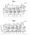
- FIG. 1 shows a high-temperature steam turbine 10 according to a particularly preferred embodiment. It can with a working medium in the form of a main flow 17 with parameters for pressure p, z. B. at 250 bar and a temperature above 540 ° C, or z. B. according to the "Neft" article, are applied.
- the steam turbine 10 has a rotor 1 with a number of rotor or rotor blades attached thereto, which are arranged in so-called blade rows 3 in a row.
- the blade rows 3 are rotatable in a housing 5, which has a number of stator blade rows 7 and thereby extends along an axial extent along an axis 9, ie in the longitudinal direction.
- the rotatable blade rows 3 engage like fingers in spaces between the stationary vane rows. 7
- housing 5 is designed as a particularly preferred embodiment of a steam turbine body according to the concept of the invention.
- the housing 5 could also be designed as an inner housing or as a guide blade carrier and / or be formed in the manner of a segmented construction of a number of housing segments.
- the housing 5 has an inner wall 11 and an outer wall 13. With the inner wall, the housing 5 defines a flow channel 15, which is provided for receiving a main flow 17 of a fluid working medium with a flow pressure.
- the housing 5 has a cooling channel system 19, which is open to the flow channel 15 and integrated in the housing 5, for receiving a cooling medium flow with a cooling medium pressure.
- a pressure reduction device 21 is arranged at the position opposite a blade row 3.
- the pressure reducing device 21 is designed to be self-regulating and able to keep the cooling medium pressure p above the flow pressure P along the longitudinal direction 9.
- the cooling medium pressure is characterized by the pressure p 1 > p 2 > p 3 , which decreases as a result of its height.
- the flow pressure is characterized by the decreasing in their sequence pressures P 1 > P 2 > P 3 .
- each self-regulating pressure reduction device 21 is designed such that p 1 > P 1 and p 2 > P 2 and p 3 > P 3 , ie along the longitudinal direction 9 is the cooling medium pressure of the cooling medium flow held above the flow pressure of the main flow 17.
- a ratio of the cooling medium pressure p to the flow pressure P is greater than 1.0 and may be up to 1.5.
- the ratio is greater than 1.1 and can be up to 1.25.
- cooling channel system 19 has a main cooling channel 23 which extends in the longitudinal direction 9 over all blade rows 3, 7.
- the cooling channel system 19 also has per guide blade stage 7 a branch cooling channel 25, which branches off from the main cooling channel 23 and is open towards the flow channel 15.
- FIG. 2 shows another particularly preferred embodiment of a high-temperature steam turbine 20, which is acted upon with steam as the working medium at a pressure above 250 bar and a temperature above 540 ° C or in modifications with steam parameters according to the "Neft" article.
- FIG. 2 are features of the same function with the same reference numerals as in FIG. 1 even though they are specified in the embodiment of the FIG. 2 in contrast to the embodiment of FIG. 1 are executed differently.
- This relates in particular to the cooling channel system 19 with the main cooling channel 23, the branch cooling channels 25 and the pressure reducing devices 21.
- the cooling channel system 19 is according to the embodiment of the FIG. 2 integrated in a rotor 31 as a particular embodiment of a steam turbine body and takes over substantially the same functions as that with respect to the FIG. 1 explained cooling channel system. Accordingly, the conditions explained for the pressures p 1 > p 2 > p 3 and P 1 > P 2 > P 3 also apply, even if the pressures now occur in different places.
- the rotor 31 delimits the flow channel 15 with its outer wall 33.
- the blade rows 35 in contrast to the blade rows 3, are the same FIG. 1 with the cooling channel system 19, and in particular designed with the branch cooling channels 25.
- the guide blade rows 27 of the housing 29 have no cooling channels.
- each pressure p is a corresponding temperature t and each pressure p is assigned a corresponding temperature T. Also for the temperatures t 1 > t 2 > t 3 and T 1 > T 2 > T 3 .
- the steam turbine casing is designed as a particularly preferred embodiment of a steam turbine body and in the embodiment of the FIG. 2 only the steam turbine rotor is designed as a particularly preferred embodiment of the steam turbine body, so in yet another embodiment not shown here, a high-temperature steam turbine, a steam turbine housing and a steam turbine rotor alike a cooling duct system 19, as it is in the 1 and 2 is shown.
- FIG. 3 shows in detail a steam turbine blade 30, as it can be used as a guide vane in the steam turbine 10 with the housing 5 as a particularly preferred embodiment of a steam turbine body.
- the detail drawing of a steam turbine blade 30 shown here is essentially also capable of a rotor blade 31 as a particularly preferred embodiment a steam turbine body of the steam turbine 20 of the FIG. 2 represent.
- the blade 30 has a blade root 37, an airfoil 39 and a blade head 41.
- the blade head 41 is presently designed in the form of a cover plate.
- the cooling channel system 19 is presently shown outside of its main cooling channel 23 only with its branch cooling channel 25.
- the branch cooling channel has a branch channel 43 which opens into an annular channel 45, wherein the annular channel 45 surrounds a row of blades whose part is the blade 30.
- a plurality of main cooling channels 23 may be arranged, of which then advantageously each a branch channel 43 or more branch channels 43 branch off to the annular channel 45. The latter are thus part of a branch cooling channel 25.
- the arrangement is preferably symmetrical to the longitudinal direction 9 in order to distribute thermal expansions evenly in the steam turbine body.
- the annular channel 45 is formed directly below the blade root 37.
- the annular channel 45 continues in the form of a blade channel 47 first into the blade root 37 and then into the blade 39.
- the blade channel 47 has an opening 49 which opens the cooling channel system 19 to the flow channel 15.
- the opening 49 opens into an area in the immediate vicinity of a head 41 of the blade 30.
- the cooling channel system 19 and the branch cooling channel 25 is thus via the branch channel 43, the annular channel 45, the blade channel 47 and the opening 49 in the region 51 to the flow channel 15th open.
- the embodiment of the FIG. 3 a guide vane, wherein the region 51 is formed in the form of a sealing region, which forms a seal 53 for sealing the blade head 41 against a rotor 55.
- the hatched area 57 represents the housing. Cooling location is thus a shaft seal.
- the hatched area 57 would represent the rotor and the non-hatched area 55 would represent the housing.
- Self-regulating pressure reducing means 21 have the particular advantage that they, in particular without external intervention, can automatically adjust to the different cooling requirements in different load cases of a steam turbine, ie in particular at full load, partial load or low load.
- a circuit arrangement of a number of self-regulating pressure reduction devices 21 in the cooling channel system 19 can be arranged such that a cooling medium flow depends on the operating state of a steam turbine 10, 20 in the cooling channel system 19 in a direction along or opposite the main flow 17 is umlagerbar.
- exemplary circuit types are in the FIGS. 7 and 8 explained.
- FIG. 4 shows a first example of a pressure reduction device 60 of the type described above.
- the detail shows the pressure reduction device 60 in a cooling channel 61, which may be a main cooling channel 23 or a branch cooling channel 25 of a cooling channel system 19 and which is designated in this case by the reference numeral 61.
- the pressure reduction device 60 in the form of a ball valve is formed by a ball 63, a seating area 65 for the ball 63 and a spring 67 to bias the ball against the force applied by a coolant flow 69.
- the spring 67 is supported against a threaded ring 71, wherein the threaded ring 71 is screwed into the cooling channel 61.
- an optional opening 73 is provided which, even if the ball 63 is firmly seated in the seating area, allows a minimum flow rate of the cooling medium 69 through the ball valve 60.
- the opening 73 thus defines a minimum cross section for the cooling channel 61 in the region of the pressure reduction device 60.
- a pressure p 1 prevails in the cooling channel 61 in front of the seat region 65 of the ball 63.
- the pressure reducing device 60 functions in such a manner that the ball 63 opens as soon as a certain pressure drop ⁇ p is exceeded.
- This specific pressure drop ⁇ p can be preset by the spring force of the spring 67 and the design of the cross section of the cooling channel 61 in the area of the pressure reducing device 60 designed as a ball valve. Decisive are essentially the opening cross section 75 and the circular ring cross section 78 between the ball and the boring wall and the opening cross section 77 of the cooling channel 61.
- a free minimum cross section which is defined by the opening 73 in the seating area 65 of the ball 63.
- the Seating area is advantageously hard-coated or otherwise armored, which increases the durability of seating area 65.
- FIG. 5 shows a functioning according to the same principle pressure reducing device 70 in the form of a closing ball valve 83, the symbol is shown in the detailed representation.
- the presetting of the pressure reduction device with respect to the pressure drop ⁇ p takes place taking into account the spring force of the spring 67 and the opening cross section 77, the circular ring section 78 between the ball and the bore and the opening cross section 79 of the cooling channel 61.
- the detail also shows a rest position 64 of the ball 63.
- the Resting position 64 the cooling channel 61 is opened in the region of relatively large overflow openings 74.
- the ball 63 is moved from its rest position 64 in its position shown in the detailed representation against the force of the spring 67, wherein the spring 67 is compressed.
- the pressure reducing device 70 is closed except for the minimum cross section 73. For this reason, the in FIG. 5 shown pressure reducing device 70 referred to as closing ball valve 83.
- FIG. 6 shows a detailed view of a pressure reducing device 80 in a cooling channel system 19.
- the illustrated cooling channel system is formed by one or a number of main cooling channels 23, one or a plurality of branch cooling channels 25 and one or a plurality of branch cooling channels 25 and one or a number of annular channels 45.
- the branch cooling channel 25 is formed by a branch channel 43 and by the annular channel 45.
- the annular channel continues into a blade channel 47, which in the present case has a blade root 37 and an airfoil 39, similar to FIG FIG. 3 shown, interspersed. Except for cooling a blade, the cooling channel system 19 can also serve to cool other suitable cooling locations.
- a number of pressure reducing devices are each arranged in the form of a differential pressure-loaded slide 85, which is mounted displaceably in a seating area 66 against a spring 68.
- the area of the pressure reducing device 80 is open through an opening 87 to the flow channel 15, wherein the flow channel 15, the main flow 17 leads. Therefore countered by each of the cooling medium pressures p 1> p 2> p 3 flow pressures P 1> P 2> P3.
- On the slider 85 thus acts on a pressure difference, which is formed by P 1 on the one hand and p 1 and p 2 on the other.
- a spring 68 is biased on the left side of the detailed representation such that the slide 85 closes the main cooling channel 23 against the coolant flow 69.
- the pressures p in the cooling channel system can be increased such that the pressure reduction device 60 opens in the left part of the detailed representation, while a pressure reduction device 80 remains closed in the right part of the detailed representation.
- cooling medium can be relocated a cooling medium flow 69 depending on the operating state of a steam turbine 10, 20 in the cooling channel system 19 in a direction along the main flow 17.
- this principle of action can also cooling medium of a cooling medium flow 69 depending on the operating condition of a Steam turbine 10, 20 are rearranged in the cooling channel system 19 in a direction opposite to the main flow 17.
- FIG. 7 shows an exemplary first type of circuit 90 of closing ball valves 83 in a coolant flow 69, which is guided in a cooling channel system 19 with a main cooling channel 23 and a branch cooling channel 25.
- the closing ball valves 83 close to a predetermined minimum cross-section after in FIG. 5 explained principle when a certain pressure difference is achieved.
- This behavior can be advantageously used in the partial load range, if an increased cooling steam mass flow 69 is required downstream of a main flow 17. In the partial load range, this is the case when, with a small pressure drop occurring in a main flow 17, a smaller cooling takes place in the course of the expansion of a working medium.
- FIG. 8 shows a second type of circuit 100 of closing ball valves 83 in a cooling passage system 19 having a main cooling passage 23 and a branch cooling passage 25.
- the closing ball valves 83 are each arranged in a branch cooling channel 25.
- the cooling channel system 19 carries a coolant flow 69.
- any throttle device 89 may be provided in the main cooling passage 23 in the present embodiment.
- the closing ball valves 83 when a certain pressure difference ⁇ p or a certain volume flow of the cooling medium 69 in the cooling channel system 19, in particular in a branch cooling channel 25 is exceeded, except for a minimum cross-section after in FIG. 5 explained principle.
- This type of second circuit 100 has the advantage that in a part-load or low-load operation of a steam turbine 10, 20 downstream of a main flow 17, an increased cooling steam mass flow 69 can be provided.
- the closing ball valves 83 then close in the front region of a main flow, while they remain open in the rear region of the main flow 17, so that an increased cooling steam mass flow 69 is provided downstream in the partial load region.
- the closing behavior is determined in particular by the pressure differences between the cooling medium flow 69 and main flow 17.
- FIGS. 7 and 8 shown circuits result from the regulation of the cooling medium pressure p in the part-load and low load range.
- a cooling medium pressure of the cooling medium 69 is readjusted to the pressure in the main flow 17.
- the cooling medium pressure of a cooling medium flow 69 remains substantially constant.
- a steam turbine body for example in the form of a housing 5 or a rotor 31 delimits along a longitudinal direction 9 a flow channel 15 which is provided for receiving a main flow 17 of a fluid working medium with a flow pressure P, P 1 > P 2 > P 3 .
- the body usually carries a number of blade rows 7, 35, which have a plurality of blades and are arranged one behind the other in the longitudinal direction 9, each extending into the flow channel 15.
- the body has a cooling channel system 19, which is open to the flow channel 15 and integrated in the body, for receiving a cooling medium flow with a cooling medium pressure p, p 1 > p 2 > p 3 .
- the presented concept provides that in the cooling channel system 19 at least one flow resistance in the form of a pressure reduction device 21, 60, 70, 80 is arranged, which is self-regulating and is designed along the Longitudinal 9 the cooling medium pressure p, p 1 > p 2 > p 3 above the flow pressure P, P 1 > P 2 > P 3 to keep.
Landscapes
- Engineering & Computer Science (AREA)
- Mechanical Engineering (AREA)
- General Engineering & Computer Science (AREA)
- Turbine Rotor Nozzle Sealing (AREA)
Description
Die Erfindung betrifft einen Dampfturbinen-Körper, der entlang einer Längsrichtung einen Strömungskanal begrenzt, der zur Aufnahme einer Hauptströmung eines fluiden Arbeitsmediums mit einem Strömungsdruck vorgesehen ist, und der ein zum Strömungskanal offenes Kühlkanalsystem zur Aufnahme einer Kühlmediumströmung mit einem Kühlmediumdruck aufweist.The invention relates to a steam turbine body which delimits along a longitudinal direction a flow channel which is provided for receiving a main flow of a fluid working medium with a flow pressure, and which has a channel open to the flow channel cooling channel system for receiving a cooling medium flow with a cooling medium pressure.
Die Erfindung betrifft des Weiteren ein Verfahren zum Kühlen einer Dampfturbine, wobei der Strömungskanal mit einer Hauptströmung eines fluiden Arbeitsmediums mit einem Strömungsdruck beaufschlagt wird, und das Kühlkanalsystem mit einer Kühlmediumströmung mit einem Kühlmediumdruck beaufschlagt wird.The invention further relates to a method for cooling a steam turbine, wherein the flow channel is acted upon by a main flow of a fluid working fluid with a flow pressure, and the cooling channel system is acted upon by a cooling medium flow with a cooling medium pressure.
Die Erfindung betrifft auch eine Verwendung.The invention also relates to a use.
Unter einer Dampfturbine im Sinne der vorliegenden Anmeldung wird jede Turbine oder Teilturbine verstanden, die von einem Arbeitsmedium in Form von Dampf durchströmt wird. Im Unterschied dazu werden Gasturbinen mit Gas und/oder Luft als Arbeitsmedium durchströmt, das jedoch völlig anderen Temperatur- und Druckbedingungen unterliegt als der Dampf bei einer Dampfturbine. Im Gegensatz zu Gasturbinen weist bei Dampfturbinen z. B. das einer Teilturbine zuströmende Arbeitsmedium mit der höchsten Temperatur gleichzeitig den höchsten Druck auf. Ein offenes Kühlsystem mit einem zum Strömungskanal offenen Kühlkanalsystem ist bei Gasturbinen auch ohne Teilturbinen-externe Zuführung von Kühlmedium realisierbar. Für eine Dampfturbine sollte eine externe Zuführung vorgesehen sein. Der Stand der Technik betreffend Gasturbinen kann schon deswegen nicht für die Beurteilung des vorliegenden Anmeldungsgegenstands herangezogen werden.For the purposes of the present application, a steam turbine is understood to mean any turbine or sub-turbine through which a working medium in the form of steam flows. In contrast, gas turbines are traversed with gas and / or air as the working medium, which, however, is subject to completely different temperature and pressure conditions than the steam in a steam turbine. In contrast to gas turbines has steam turbines z. As the one part turbine incoming working fluid with the highest temperature at the same time the highest pressure. An open cooling system with a cooling channel system which is open to the flow channel can also be implemented in the case of gas turbines without partial turbine-external supply of cooling medium. For a steam turbine, an external supply should be provided. For this reason, the prior art relating to gas turbines can not be used for the assessment of the subject of the present application.
Ein einen Strömungskanal begrenzender Dampfturbinen-Körper kann in Form eines Rotors oder eines Gehäuses gebildet sein. Eine Dampfturbine umfasst üblicherweise einen mit Schaufeln besetzten drehbar gelagerten Rotor, der innerhalb eines Gehäuses bzw. Gehäusemantels angeordnet ist. Bei Durchströmung des vom Gehäusemantel gebildeten Innenraums des Strömungskanals mit erhitztem und unter Druck stehendem Dampf wird der Rotor über die Schaufeln durch den Dampf in Drehung versetzt. Die Schaufeln des Rotors werden auch als Laufschaufeln bezeichnet. Diese sind üblicherweise als Laufschaufelreihe entlang des Außenumfangs an der Außenseite des Rotors angeordnet. Am Gehäusemantel sind darüber hinaus üblicherweise stationäre Leitschaufeln aufgehängt, welche entlang einer axialen Ausdehnung des Körpers in die Zwischenräume der Rotorschaufeln greifen. Eine Leitschaufel ist üblicherweise an einer ersten Stelle entlang einer Innenseite des Dampfturbinen-Gehäuses gehalten. Dabei ist sie üblicherweise Teil einer Leitschaufelreihe, welche eine Anzahl von Leitschaufeln umfasst, die entlang eines Innenumfangs an der Innenseite des Dampfturbinen-Gehäuses angeordnet sind. Dabei weist jede Leitschaufel mit ihrem Schaufelblatt radial nach innen. Eine Leitschaufelreihe an der genannten ersten Stelle entlang der axialen Ausdehnung wird auch als Leitschaufelgitter oder -kranz bezeichnet. Üblicherweise sind eine Anzahl von Leitschaufelreihen hintereinander geschaltet. Entsprechend ist an einer zweiten Stelle entlang der axialen Ausdehnung hinter der ersten Stelle eine weitere zweite Schaufel entlang der Innenseite des Dampfturbinen-Gehäuses gehalten. Ein Paar einer Laufschaufelreihe und einer Leitschaufelreihe wird auch als Schaufelstufe bezeichnet.A steam turbine body defining a flow passage may be formed in the form of a rotor or a housing. A steam turbine typically comprises a rotor-mounted rotatably mounted rotor disposed within a housing. When flowing through the interior of the flow channel formed by the housing shell with heated and pressurized steam, the rotor is rotated by the vanes through the steam. The blades of the rotor are also referred to as blades. These are usually arranged as a blade row along the outer periphery on the outside of the rotor. In addition, usually stationary guide vanes are suspended on the housing jacket, which engage along an axial extent of the body in the interspaces of the rotor blades. A vane is typically held at a first location along an interior of the steam turbine casing. In this case, it is usually part of a stator blade row, which comprises a number of guide vanes, which are arranged along an inner circumference on the inside of the steam turbine housing. Each vane has its blade radially inward. A row of vanes at said first location along the axial extent is also referred to as a vane grille or crown. Usually, a number of rows of blades are connected in series. Accordingly, at a second location along the axial extent behind the first location, a further second blade is held along the inside of the steam turbine housing. A pair of blade rows and a guide blade row is also referred to as a blade stage.
Der Gehäusemantel einer derartigen Dampfturbine kann aus einer Anzahl von Gehäusesegmenten gebildet sein. Unter dem Gehäusemantel der Dampfturbine ist insbesondere das stationäre Gehäusebauteil einer Dampfturbine oder einer Teilturbine zu verstehen, das entlang der Längsrichtung der Dampfturbine einen Innenraum in Form eines Strömungskanals aufweist, der zur Durchströmung mit dem Arbeitsmedium in Form von Dampf vorgesehen ist. Dies kann, je nach Dampfturbinenart, ein Innengehäuse und/oder ein Leitschaufelträger sein. Es kann aber auch ein Turbinengehäuse vorgesehen sein, welches kein Innengehäuse oder keinen Leitschaufelträger aufweist.The housing jacket of such a steam turbine can be formed from a number of housing segments. The housing shell of the steam turbine is to be understood in particular as the stationary housing component of a steam turbine or a partial turbine, which runs along the longitudinal direction of the steam turbine Having interior space in the form of a flow channel, which is provided for flow through the working medium in the form of vapor. Depending on the steam turbine type, this can be an inner casing and / or a guide vane carrier. However, it may also be provided a turbine housing, which has no inner housing or no guide vane.
Aus Wirkungsgradgründen kann die Auslegung einer derartigen Dampfturbine für so genannte "hohe Dampfparameter", also insbesondere hohe Dampfdrücke und/oder hohe Dampftemperaturen, wünschenswert sein. Allerdings ist insbesondere eine Temperaturerhöhung aus materialtechnischen Gründen nicht unbegrenzt möglich. Um dabei einen sicheren Betrieb der Dampfturbine auch bei besonders hohen Temperaturen zu ermöglichen, kann daher eine Kühlung einzelner Bauteile oder Komponenten wünschenswert sein. Die Bauteile sind nämlich in ihrer Temperaturfestigkeit begrenzt. Ohne effiziente Kühlung würden bei steigenden Temperaturen wesentlich teurere Materialien (z. B. Nickelbasislegierungen) nötig.For efficiency reasons, the design of such a steam turbine for so-called "high steam parameters", ie in particular high steam pressures and / or high steam temperatures, may be desirable. However, in particular a temperature increase for reasons of material technology is not unlimited possible. In order to enable safe operation of the steam turbine even at particularly high temperatures, therefore, cooling of individual components or components may be desirable. The components are limited in their temperature resistance. Without efficient cooling, more expensive materials (eg, nickel-based alloys) would be required as temperatures rise.
Bei den bisher bekannten Kühlmethoden, insbesondere für einen Dampfturbinen-Körper in Form eines Dampfturbinen-Gehäuses oder eines Rotors, ist zwischen einer aktiven Kühlung und einer passiven Kühlung zu unterscheiden. Bei einer aktiven Kühlung wird eine Kühlung durch ein dem Dampfturbinen-Körper separat, d. h. zusätzlich zum Arbeitsmedium zugeführtes Kühlmedium bewirkt. Dagegen erfolgt eine passive Kühlung lediglich durch eine geeignete Führung oder Verwendung des Arbeitsmediums. Bisher wurden Dampfturbinen-Körper vorzugsweise passiv gekühlt.In the cooling methods known hitherto, in particular for a steam turbine body in the form of a steam turbine housing or a rotor, a distinction must be made between active cooling and passive cooling. With active cooling, cooling is provided separately by a steam turbine body, i. H. effected in addition to the working medium supplied cooling medium. In contrast, a passive cooling is done only by a suitable leadership or use of the working medium. So far, steam turbine bodies have preferably been passively cooled.
So ist beispielsweise aus der
Eine Schaufelkühlung ist aus der
In der
Aus der
Aus den Druckschriften
In der
Aus der
In der Strömungsleitung ist ein regelbares Ventil angeordnet, das von einer Regeleinheit betrieben wird. Darüber hinaus sind in der Strömungsleitung Drucksensoren angeordnet, die Signale zu der Regeleinheit senden. Dadurch kann abhängig von der gewünschten Kühlleistung der Massenstrom des Kühldampfes in der Strömungsleitung geregelt werden.In the flow line, a controllable valve is arranged, which is operated by a control unit. In addition, pressure sensors are arranged in the flow line, which send signals to the control unit. As a result, depending on the desired cooling capacity, the mass flow of the cooling steam in the flow line can be regulated.
Zur Erzielung höherer Wirkungsgrade bei der Stromerzeugung mit fossilen Brennstoffen besteht das Bedürfnis, bei einer Turbine höhere Dampfparameter, d. h. höhere Drücke und Temperaturen als bisher üblich anzuwenden. Bei Hochtemperatur-Dampfturbinen sind beim Dampf als Arbeitsmedium Temperaturen zum Teil weit über 500 °C, insbesondere über 540 °C, vorgesehen. Diese Parameter machen eine Hochtemperatur-Dampfturbine aus. Im Detail sind solche Dampfparameter für Hochtemperatur-Dampfturbinen in dem Artikel "
Insbesondere sind Beispiele höherer Dampfparameter für Hochtemperatur-Dampfturbinen in Bild 13 des Artikels genannt. In dem genannten Artikel wird zur Verbesserung der Kühlung eines Hochtemperatur-Dampfturbinen-Gehäuses eine Kühldampfzufuhr und Weiterleitung des Kühldampfs durch die erste Leitschaufelreihe vorgeschlagen. Damit wird zwar eine aktive Kühlung bereitgestellt. Diese ist jedoch auf den Hauptströmungsbereich des Arbeitsmediums beschränkt und noch verbesserungswürdig.In particular, examples of higher steam parameters for high-temperature steam turbines are mentioned in Figure 13 of the article. In the cited article, a cooling steam supply and forwarding of the cooling steam through the first row of guide vanes is proposed for improving the cooling of a high-temperature steam turbine housing. This provides active cooling. However, this is limited to the main flow of the working medium and still in need of improvement.
Alle bisher bekannten Kühlverfahren für ein Dampfturbinen-Gehäuse sehen also, soweit es sich überhaupt um aktive Kühlverfahren handelt, allenfalls ein gezieltes Anströmen eines separaten und zu kühlenden Turbinenteiles vor und sind auf den Einströmbereich des Arbeitsmediums, allenfalls unter Einbeziehung des ersten Leitschaufelkranzes, beschränkt. Dies kann bei einer Belastung üblicher Dampfturbinen mit höheren Dampfparametern zu einer auf die ganze Turbine wirkenden, erhöhten thermischen Belastung führen, welche durch eine oben beschriebene übliche Kühlung des Gehäuses nur unzureichend abgebaut werden könnte. Dampfturbinen, die zur Erzielung höherer Wirkungsgrade grundsätzlich mit höheren Dampfparametern arbeiten, benötigen eine verbesserte Kühlung, insbesondere des Gehäuses und/oder des Rotors, um eine höhere thermische Belastung der Dampfturbine in genügendem Maße abzubauen. Dabei besteht das Problem, dass bei der Nutzung bisher üblicher Turbinenmaterialien die zunehmende Beanspruchung des Dampfturbinen-Körpers durch erhöhte Dampfparameter, z. B. gemäß dem "Neft"-Artikel, zu einer nachteiligen thermischen Belastung des Körpers führen kann, so dass diese technisch nicht mehr ausführbar sind.All previously known cooling methods for a steam turbine housing thus see, as far as it is at all active cooling method, at best a targeted flow against a separate turbine part to be cooled and are on the inflow of the working medium, at most, including of the first vane ring, limited. This may result in a load of conventional steam turbines with higher steam parameters to an acting on the entire turbine, increased thermal load, which could be reduced only inadequately by a conventional cooling of the housing described above. Steam turbines, which generally operate with higher steam parameters to achieve higher efficiencies, require improved cooling, in particular of the housing and / or of the rotor, in order to sufficiently reduce a higher thermal load on the steam turbine. There is the problem that when using previously customary turbine materials, the increasing stress of the steam turbine body by increased steam parameters, eg. B. according to the "Neft" article, can lead to adverse thermal stress on the body, so that they are technically no longer executable.
In den veröffentlichten europäischen Patentanmeldungen
Soweit die übrigen oben genannten Dokumente überhaupt eine aktive Kühlung offenbaren, erweist sich diese im Einzelnen als nicht ausreichend wirkungsvoll und in ihrer mechanischen Konstruktion als nachteilig.Insofar as the other documents mentioned above reveal any active cooling, this proves to be more specific as not sufficiently effective and disadvantageous in its mechanical construction.
Wünschenswert wäre eine konstruktiv einfache und gleichzeitig effiziente aktive Kühlung bei einem Dampfturbinen-Körper der eingangs genannten Art.Desirable would be a structurally simple and at the same time efficient active cooling in a steam turbine body of the type mentioned.
An dieser Stelle setzt die Erfindung an, deren Aufgabe es ist, einen Dampfturbinen-Körper, eine Dampfturbine und ein Verfahren zur Kühlung einer Dampfturbine sowie eine Verwendung anzugeben, bei der insbesondere das Kühlkanalsystem mechanisch vorteilhaft und gleichzeitig in seiner Kühlwirkung effizient und flexibel ausgelegt ist.At this point, the invention begins, whose task is to provide a steam turbine body, a steam turbine and a method for cooling a steam turbine and a use in which in particular the cooling duct system is designed to be mechanically advantageous and at the same time efficient and flexible in its cooling effect.
Bezüglich des Dampfturbinen-Körpers wird diese Aufgabe erfindungsgemäß dadurch gelöst, dass im Kühlkanalsystem wenigstens ein Strömungswiderstand in Form einer Druckminderungseinrichtung angeordnet ist, die selbstregelnd ist und ausgelegt ist, entlang der Längsrichtung den Kühlmediumdruck über dem Strömungsdruck zu halten.With regard to the steam turbine body, this object is achieved according to the invention in that at least one flow resistance in the form of a pressure reduction device is arranged in the cooling channel system, which is self-regulating and designed to keep the cooling medium pressure above the flow pressure along the longitudinal direction.
Auf diese Weise wird nämlich garantiert, dass der strömungsnahe Bereich des Dampfturbinen-Körpers ständig mit Kühlmedium beaufschlagt ist. Um dabei eine besonders zuverlässige und bedarfsgerechte Kühlwirkung zu erzielen, sind die Kühlkanäle vorteilhafterweise vergleichsweise oberflächennah an der Innenoberfläche des Gehäusemantels geführt. Dem liegt die Erkenntnis zugrunde, dass gerade bei der Führung vergleichsweise heißen Strömungsmediums im Strömungskanal die thermische Belastung an einer Oberfläche des Dampfturbinen-Körpers besonders hoch ist. Eine besonders bedarfsgerechte Kühlung ist somit erreichbar, indem der jeweilige Kühlkanal vorteilhafterweise innerhalb einer Wand des jeweiligen Dampfturbinen-Körpers relativ zur Mittelebene der Wand in Richtung zur Oberfläche, also zur den Strömungskanal begrenzenden Oberfläche, hin versetzt positioniert ist.In this way, it is guaranteed that the near-flow area of the steam turbine body is constantly supplied with cooling medium. In order to achieve a particularly reliable and needs-based cooling effect, the cooling channels are advantageously performed comparatively close to the surface of the surface of the housing shell. This is based on the knowledge that especially in the leadership comparatively hot flow medium in the flow channel, the thermal load on a surface of the steam turbine body is particularly high. A particularly needs-based cooling is thus achievable by the respective cooling channel advantageously within a wall of the respective steam turbine body relative to the center plane of the wall in the direction of the surface, ie the flow channel bounding surface, positioned offset.
Vorzugsweise ist das Kühlkanalsystem im Dampfturbinen-Körper integriert. Dabei kann das Kühlkanalsystem beispielsweise durch Hohlräume und/oder Kanäle im Körper selbst gebildet sein. Vorzugsweise kann das Kühlkanalsystem auch durch Abschirmbleche oder -elemente und den Körper selbst gebildet sein, indem die Abschirmbleche oder -elemente beabstandet vom Körper am Körper angebracht sind und ein Kühlkanalsystem in Form der durch die Beabstandung gebildeten Kanäle und Hohlräume gebildet ist.Preferably, the cooling channel system is integrated in the steam turbine body. In this case, the cooling channel system may be formed, for example, by cavities and / or channels in the body itself. Preferably, the cooling channel system can also be formed by shielding plates or elements and the body itself, by the shielding plates or elements spaced from the body are attached to the body and a cooling channel system is formed in the form of the channels formed by the spacing and cavities.
Gemäß der Erfindung ist in einem solchen Kühlkanalsystem ein Strömungswiderstand in Form einer Druckminderungseinrichtung angeordnet, die vorliegend selbstregelnd ausgelegt ist. Es handelt sich dabei also um eine Einrichtung, die von einer bloßen in der
Eine auf solche Weise ausgelegte Anzahl von selbstregelnden Druckminderungseinrichtungen vermag entlang der Längsrichtung den Kühlmediumdruck über dem Strömungsdruck zu halten.A number of self-regulating pressure reducing means designed in such a way can maintain the cooling medium pressure above the flow pressure along the longitudinal direction.
Eine solche speziell für die Funktion der Druckminderung ausgestaltete Druckminderungseinrichtung ermöglicht es vorteilhafterweise einen praktisch optimalen Kühlmediumdruck zu erreichen. Gewisse Nachteile, wie sie durch in der
Das Kühlkanalsystem weist einen Hauptkühlkanal auf, der sich in Längsrichtung über eine Ausdehnung wenigstens einer Schaufelreihe erstreckt. Des Weiteren weist das Kühlkanalsystem einen Zweigkühlkanal auf, der vom Hauptkühlkanal abzweigt und zum Strömungskanal offen ist. Auf diese Weise lässt sich nämlich ein besonders effizientes und vorteilhaft gleichzeitig oberflächennahes im Körper integriertes Kühlkanalsystem mit möglichst großer der Körperform angepasster Kühloberfläche realisieren. Eine Druckminderungseinrichtung kann auch in einem Zweigkühlkanal angeordnet sein.The cooling channel system has a main cooling channel which extends in the longitudinal direction over an extension of at least one blade row. Furthermore, the cooling channel system has a branch cooling channel, which branches off from the main cooling channel and is open to the flow channel. In this way, namely, a particularly efficient and advantageously at the same time near-surface cooling channel system integrated in the body can be realized with the largest possible cooling surface adapted to the body shape. A pressure reduction device can also be arranged in a branch cooling channel.
Bei dem so aufgebauten Kühlkanalsystem sind eine oder mehrere Druckminderungseinrichtungen im Hauptkühlkanal angeordnet. Bei jedem Hauptkühlkanal kann beispielsweise für jede Schaufelreihe und/oder Schaufelstufe jeweils eine Druckminderungseinrichtung vorgesehen sein. Gemäß einer besonders vorteilhaften Ausführungsform geht der Zweigkühlkanal von der Druckminderungseinrichtung aus. Alternativ oder zusätzlich könnte eine Druckminderungseinrichtung darüber hinaus auch zwischen zwei Zweigkühlkanälen im Hauptkühlkanal angeordnet sein.In the thus constructed cooling channel system, one or more pressure reducing devices are arranged in the main cooling channel. For each main cooling channel, for example, one pressure reduction device may be provided for each blade row and / or blade stage. According to a particularly advantageous embodiment, the branch cooling channel starts from the pressure reduction device. Alternatively or additionally, a pressure reduction device could also be arranged between two branch cooling channels in the main cooling channel.
Vorteilhafte Weiterbildungen der Erfindung sind den Unteransprüchen zu entnehmen und geben im Einzelnen vorteilhafte Möglichkeiten an, das Kühlkanalsystem einerseits und die Druckminderungseinrichtung andererseits, im Rahmen oben erläuterter Aufgabe hinsichtlich weiterer Vorteile zu realisieren.Advantageous developments of the invention can be found in the dependent claims and specify in particular advantageous ways to realize the cooling duct system on the one hand and the pressure reducing device on the other hand, in the context of the above-explained object with regard to further advantages.
Hinsichtlich der Druckminderungseinrichtung erweist es sich als besonders vorteilhaft, diese in Form eines vorzugsweise gegen die Kühlmediumströmung federbelasteten Kugelventils zu bilden.With regard to the pressure reducing device, it proves to be particularly advantageous to form these in the form of a preferably spring-loaded against the cooling medium flow ball valve.
In einer alternativen Ausführungsform erweist es sich als vorteilhaft, die Druckminderungseinrichtung in Form eines vorzugsweise gegen die Kühlmediumströmung vorgespannten Schiebers auszubilden. Der Schieber kann insbesondere differenzdruckbeaufschlagt sein. Der Differenzdruck kann dabei vorteilhaft von Kühlmediumströmung und Hauptströmung gebildet sein.In an alternative embodiment, it proves to be advantageous, the pressure reduction device in the form of a preferably form against the cooling medium flow biased slide. The slider may in particular be subjected to differential pressure. The differential pressure can advantageously be formed by cooling medium flow and main flow.
Beide Weiterbildungen sind in Form einer besonders bevorzugten Ausführungsform im Zusammenhang mit der Zeichnung im Detail beschrieben.Both developments are described in the form of a particularly preferred embodiment in connection with the drawing in detail.
Gemäß einer Weiterbildung des so aufgebauten Kühlkanalsystems erweist es sich als vorteilhaft, dass der Körper eine Anzahl von, mehrere Schaufeln aufweisende, in Längsrichtung hintereinander angeordnete Schaufelreihen trägt, die sich jeweils in den Strömungskanal erstrecken und wobei der Zweigkühlkanal einen eine Schaufelreihe umgebenden Ringkanal aufweist. Dazu könnte beispielsweise zunächst ein Stichkühlkanal von einem Hauptkühlkanal auf einen Ringkanal führen. Ein solcher Ringkanal ist vorzugsweise pro Schaufelreihe an der Position einer Schaufelreihe vorgesehen, insbesondere direkt unterhalb der Verankerung eines Schaufelfußes einer Schaufel der Schaufelreihe. Insbesondere verläuft ein Ringkanal im Rotor innerhalb einer Laufschaufelreihe. Insbesondere umgibt ein Ringkanal im Gehäuse eine Leitschaufelreihe.According to a further development of the cooling channel system constructed in this way, it proves to be advantageous for the body to carry a number of blade rows, which have a plurality of blades and are arranged one behind the other in the longitudinal direction, which each extend into the flow channel and wherein the branch cooling channel has an annular channel surrounding a row of blades. For this purpose, for example, could first lead a Stichkühlkanal of a main cooling channel on a ring channel. Such an annular channel is preferably provided per row of blades at the position of a row of blades, in particular directly below the anchoring of a blade root of a blade of the blade row. In particular, an annular channel runs in the rotor within a blade row. In particular, a ring channel in the housing surrounds a row of guide vanes.
Gemäß noch einer Weiterbildung eines derart aufgebauten Kühlkanalsystems weist der Zweigkühlkanal einen oder mehrere von einem Ringkanal ausgehende Schaufelkanäle auf, die in eine, eine Anzahl oder alle Schaufeln einer Schaufelstufe führen.According to a further development of a cooling channel system constructed in this way, the branch cooling channel has one or more blade channels which originate from an annular channel and lead into one, a number or all blades of a blade stage.
Gemäß dieser Weiterbildung wird also ein Kühlmedium parallel zur Expansion einer Hauptströmung schrittweise durch speziell dafür vorgesehene Einrichtungen gedrosselt sowie einzelnen oder mehreren Schaufelreihen und/oder Schaufelstufen zugeführt zur Kühlung einer jeweiligen Schaufel. Das Kühlmedium kann dabei vorzugsweise in Form von Dampf oder bei einigen Anwendungen ggf. auch in Form von Wasser von externer Seite dem Kühlkanalsystem zugeführt werden. Beispielsweise kann Kühlmedium in Form von Dampf dem Dampfkreislauf auf geeignete Weise entnommen werden.According to this embodiment, therefore, a cooling medium is parallel to the expansion of a main flow gradually throttled through specially provided facilities and fed to individual or more blade rows and / or blade stages for cooling a respective blade. The cooling medium may preferably be in the form of steam or some Applications may also be supplied in the form of water from the outside of the cooling channel system. For example, cooling medium in the form of steam can be removed from the steam cycle in a suitable manner.
Gemäß dieser Weiterbildung tritt das Kühlmedium durch hohl gebohrte oder durch hohl gegossene Schaufeln vorteilhaft in einen Bereich oberhalb des Schaufelkopfes. Zusätzlich können weitere Öffnungen in einer Schaufel vorgesehen sein, um einen Kühlmediumsaustritt zu ermöglichen und um damit eine Oberflächenkühlung in Form einer Filmkühlung auf der Schaufeloberfläche bereitzustellen. Insbesondere kann das Kühlmedium auch an einer Stelle des Dampfturbinenkörpers austreten, an der keine Schaufelreihe angeordnet ist. Vorteilhaft ist dabei jede zweckmäßig zu kühlende Bauteiloberfläche kühlbar. Beispielsweise ist dadurch ein Dichtungsbereich zwischen einem Dampfturbinenkörper und einer Schaufelreihe kühlbar.According to this development, the cooling medium passes through hollow drilled or hollow-cast blades advantageously in an area above the blade head. In addition, further openings may be provided in a blade to allow cooling media exit and thereby provide surface cooling in the form of film cooling on the blade surface. In particular, the cooling medium can also emerge at a point of the steam turbine body on which no blade row is arranged. Advantageously, each useful to be cooled component surface is coolable. For example, a sealing area between a steam turbine body and a row of blades can thereby be cooled.
Mit dieser Form der Weiterbildung ist eine übermäßige Druckbeanspruchung der besonders zu kühlenden Bauteile in Form der Schaufeln durch ein nicht druckangepasstes Medium vermieden. Gleichzeitig ist ein vorbestimmter, erforderlicher Differenzdruck zur Sicherstellung eines ausreichenden Kühlmassenstroms durch die selbstregelnden Druckminderungseinrichtungen garantiert. Denn das Kühlmedium wird bei dieser Weiterbildung von den Druckminderungseinrichtungen aus in Kühlkanäle geleitet, an die einige oder alle Schaufeln einer Schaufelstufe angeschlossen sind.With this form of development an excessive compressive stress of the components to be cooled particularly in the form of the blades by a non-pressure-adapted medium is avoided. At the same time a predetermined, required differential pressure to ensure a sufficient flow of cooling mass is guaranteed by the self-regulating pressure reduction devices. Because the cooling medium is passed in this development of the pressure reduction devices in cooling channels, to which some or all blades of a blade stage are connected.
Dabei kann das hier vorgeschlagene Kühlkanalsystem mechanisch vorteilhaft und gleichzeitig effizient und flexibel ausgebildet sein, da fest vorzugebende konstruktive und geometrische Maßnahmen zur Drosselung des Kühlmediums vermieden sind. Statt dessen wird gemäß dem vorgelegten Konzept eine Anzahl von selbstregelnden Druckminderungseinrichtungen verwendet.In this case, the cooling duct system proposed here can be designed to be mechanically advantageous and, at the same time, efficient and flexible, since fixed structural and geometric measures for throttling the cooling medium are avoided. Instead, according to the concept presented, a number of self-regulating pressure reducing devices are used.
Aus Gründen gleichmäßiger Verformung eines thermisch beanspruchten Dampfturbinen-Körpers ist eine symmetrische Anordnung des Kühlkanalsystem, insbesondere der erwähnten Hauptkühlkanäle, Stichkühlkanäle und Schaufelkühlkanäle, insbesondere in Bezug auf den Ringkühlkanal, vorzuziehen. In dem Fall lassen sich die Druckminderungseinrichtungen des Kühlkanalsystems in ihrer Funktion besser den Erfordernissen der unterschiedlichen Kühlanforderungen bei Teillasten anpassen. Eine solche Anpassung wäre bei einem lediglich konstruktiv und damit mit fester Geometrie vorgegebenen Kühlkanalsystem nicht möglich.For reasons of uniform deformation of a thermally stressed steam turbine body is a symmetrical arrangement of the cooling channel system, in particular the mentioned main cooling channels, trickle cooling channels and blade cooling channels, in particular with respect to the annular cooling channel, preferable. In this case, the pressure reducing means of the cooling duct system can be better adapted in function of the requirements of the different cooling requirements at partial loads. Such an adaptation would not be possible with a cooling duct system which is merely constructive and therefore fixed geometry.
Ausführungsbeispiele der Erfindung werden nachfolgend anhand der Zeichnung beschrieben. Diese soll die Ausführungsbeispiele nicht maßgeblich darstellen, vielmehr ist die Zeichnung, wo zur Erläuterung dienlich, in schematisierter und/oder leicht verzerrter Form ausgeführt. Im Hinblick auf Ergänzungen der aus der Zeichnung unmittelbar erkennbaren Lehren wird auf den einschlägigen Stand der Technik verwiesen. Im Einzelnen zeigt die Zeichnung in:
- FIG 1
- eine schematisierte Darstellung eines Kühlkanalsystems mit selbstregelnden Druckminderungseinrichtungen bei einem Dampfturbinen-Gehäuse gemäß einer bevorzugten Ausführungsform;
- FIG 2
- eine schematisierte Darstellung eines Kühlkanalsystems mit selbstregelnden Druckminderungseinrichtungen bei einem Dampfturbinen-Rotor gemäß einer bevorzugten Ausführungsform;
- FIG 3
- eine Darstellung einer Zuführung eines Kühlmediums und der Weiterleitung des Kühlmediums in einem im Dampfturbinen-Körper integrierten, oberflächennahen Kühlkanalsystem im Beschaufelungsbereich für eine bevorzugte Ausführungsform eines Dampfturbinen-Gehäuses oder -Rotors;
- FIG 4
- eine Detaildarstellung einer Druckminderungseinrichtung in Form eines gegen die Kühlmediumströmung federbelasteten Kugelventils bei einer der besonders bevorzugten Ausführungsformen der
FIG 1 , wobei das Kugelventil öffnet, wenn ein Grenzdruck überschritten wird;bis 3 - FIG 5
- eine Detaildarstellung einer Druckminderungseinrichtung in Form eines gegen die Kühlmediumströmung federbelasteten Kugelventils bei einer der besonders bevorzugten Ausführungsformen der
FIG 1 , wobei das Kugelventil schließt, wenn ein Grenzdruck überschritten wird;bis 3 - FIG 6
- eine Detaildarstellung einer selbstregelnden Druckminderungseinrichtung in Form eines differenzdruckbeaufschlagten, vorgespannten Schiebers bei einer der bevorzugten Ausführungsformen der
FIG 1 ;bis 3 - FIG 7
- ein Diagramm für eine beispielhafte Schaltungsart von Kugelventilen in einem Hauptkühlkanal bei einer der besonders bevorzugten Ausführungsformen der
FIG 1 bis FIG 3 ; - FIG 8
- ein Diagramm für eine beispielhafte Schaltungsart von Kugelventilen in Nebenkühlkanälen bei einer besonders bevorzugten Ausführungsform der
FIG 1 bis FIG 3 .
- FIG. 1
- a schematic representation of a cooling duct system with self-regulating pressure reducing means in a steam turbine housing according to a preferred embodiment;
- FIG. 2
- a schematic representation of a cooling duct system with self-regulating pressure reducing means in a steam turbine rotor according to a preferred embodiment;
- FIG. 3
- a representation of a supply of a cooling medium and the forwarding of the cooling medium in a built-in steam turbine body, near-surface cooling channel system in the blading region for a preferred embodiment of a steam turbine housing or rotor;
- FIG. 4
- a detailed view of a pressure reducing device in the form of a spring-loaded against the cooling medium flow ball valve in one of the particularly preferred embodiments of
1 to 3 wherein the ball valve opens when a limit pressure is exceeded; - FIG. 5
- a detailed view of a pressure reducing device in the form of a spring-loaded against the cooling medium flow ball valve in one of the particularly preferred embodiments of
1 to 3 wherein the ball valve closes when a limit pressure is exceeded; - FIG. 6
- a detailed view of a self-regulating pressure reducing device in the form of a druckbeaufschlagten biased slide in one of the preferred embodiments of
1 to 3 ; - FIG. 7
- a diagram for an exemplary circuit type of ball valves in a main cooling channel in one of the particularly preferred embodiments of
1 to FIG. 3 ; - FIG. 8
- a diagram of an exemplary circuit type of ball valves in secondary cooling channels in a particularly preferred embodiment of the
1 to FIG. 3 ,
Das in
Der Kühlmediumdruck ist vorliegend durch die in ihrer Höhe infolge abnehmenden Drücke p1>p2>p3 gekennzeichnet. Ebenso ist der Strömungsdruck durch die in ihrer Folge abnehmenden Drücke P1>P2>P3 gekennzeichnet. Im Übrigen ist vorliegend jede selbstregelnde Druckminderungseinrichtung 21 so ausgelegt, dass p1>P1 und p2>P2 und p3>P3 gilt, d. h. entlang der Längsrichtung 9 ist der Kühlmediumdruck der Kühlmediumströmung über dem Strömungsdruck der Hauptströmung 17 gehalten. Ein Verhältnis des Kühlmediumdrucks p zum Strömungsdruck P ist größer als 1.0 und kann bis 1.5 betragen. Vorteilhaft ist das Verhältnis größer als 1.1 und kann bis zu 1.25 betragen.In the present case, the cooling medium pressure is characterized by the pressure p 1 > p 2 > p 3 , which decreases as a result of its height. Likewise, the flow pressure is characterized by the decreasing in their sequence pressures P 1 > P 2 > P 3 . Incidentally, in the present case, each self-regulating
Das in der
Die detaillierte Ausführung des Kühlkanalsystems 19 im Bereich einer Schaufelstufe 3, 7 wird im Detail in der
In der
Das Kühlkanalsystem 19 ist gemäß der Ausführungsform der
Vorliegend begrenzt der Rotor 31 mit seiner Außenwandung 33 den Strömungskanal 15. Allerdings sind diesmal die Laufschaufelreihen 35 im Unterschied zu den Laufschaufelreihen 3 der
Ähnlich wie die Drücke p und P verhalten sich in der Regel auch die Temperaturen t des Kühlmediums und T des Arbeitsmediums. Das heißt, jedem Druck p ist eine entsprechende Temperatur t und jedem Druck p ist eine entsprechende Temperatur T zugeordnet. Auch für die Temperaturen gilt hier t1>t2>t3 und T1>T2>T3 .Similar to the pressures p and P, the temperatures t of the cooling medium and T of the working medium also generally behave. That is, each pressure p is a corresponding temperature t and each pressure p is assigned a corresponding temperature T. Also for the temperatures t 1 > t 2 > t 3 and T 1 > T 2 > T 3 .
Auch wenn in der Ausführungsform der
Die Detailzeichnung der
Die Schaufel 30 weist einen Schaufelfuß 37, ein Schaufelblatt 39 und einen Schaufelkopf 41 auf. Der Schaufelkopf 41 ist vorliegend in Form einer Deckplatte ausgebildet. Das Kühlkanalsystem 19 ist vorliegend außerhalb seines Hauptkühlkanals 23 lediglich mit seinem Zweigkühlkanal 25 gezeigt. Der Zweigkühlkanal weist einen Stichkanal 43 auf, der in einen Ringkanal 45 mündet, wobei der Ringkanal 45 eine Schaufelreihe, dessen Teil die Schaufel 30 ist, umgibt. Entlang des Umfangs der Schaufelreihe können mehrere Hauptkühlkanäle 23 angeordnet sein, von denen dann vorteilhaft jeweils ein Stichkanal 43 oder mehrere Stichkanäle 43 zum Ringkanal 45 abzweigen. Letztere sind somit Teil eines Zweigkühlkanals 25. Die Anordnung ist vorzugsweise symmetrisch zur Längsrichtung 9, um thermische Ausdehnungen beim Dampfturbinen-Körper gleichmäßig zu verteilen.The
Der Ringkanal 45 ist direkt unterhalb des Schaufelfußes 37 gebildet. Der Ringkanal 45 setzt sich in Form eines Schaufelkanals 47 zunächst in den Schaufelfuß 37 und dann in das Schaufelblatt 39 fort. Es vermag je nach Anwendung eine, mehrere oder alle Schaufeln 30 einer Schaufelstufe einen hier gezeigten Schaufelkanal 47 aufweisen. Der Schaufelkanal 47 weist eine Öffnung 49 auf, die das Kühlkanalsystem 19 zum Strömungskanal 15 öffnet. Die Öffnung 49 mündet dabei in einen Bereich in unmittelbarer Nähe eines Kopfes 41 der Schaufel 30. Das Kühlkanalsystem 19 bzw. der Zweigkühlkanal 25 ist somit über den Stichkanal 43, den Ringkanal 45, den Schaufelkanal 47 und die Öffnung 49 im Bereich 51 zum Strömungskanal 15 offen.The
Im vorliegenden Fall zeigt die Ausführungsform der
Für denn Fall, dass die Schaufel 30 eine Laufschaufel darstellen würde, würde der schraffierte Bereich 57 den Rotor darstellen und der nicht schraffierte Bereich 55 das Gehäuse.For the case that the
In den
Das ist insbesondere im Rahmen der im Folgenden erläuterten Kühlanforderungen vorteilhaft. Bei Volllast nimmt die Temperatur einer Hauptströmung 17 nämlich im Verlauf der Expansion eines Arbeitsmediums stark ab. Kühlbedarf besteht deshalb insbesondere im vorderen Teil des Expansionsbereiches des Arbeitsmediums im Strömungskanal 15. Bei Teillast oder Schwachlast stellt sich dagegen eine geringere Absenkung der Temperatur ein, was insbesondere aufgrund von Ventilation erfolgt. Das heißt, bei gleichbleibender Eintrittstemperatur sollte bei Teillast oder Schwachlast ein ausgedehnterer Bereich im Vergleich zur Volllast gekühlt werden. In dem Zusammenhang lässt sich insbesondere eine Schaltungsanordnung einer Anzahl selbstregelnder Druckminderungseinrichtungen 21 im Kühlkanalsystem 19 derart anordnen, dass eine Kühlmediumströmung abhängig vom Betriebszustand einer Dampfturbine 10, 20 in dem Kühlkanalsystem 19 in einer Richtung entlang oder entgegen der Hauptströmung 17 umlagerbar ist. Dafür beispielhafte Schaltungsarten sind in den
Unter der Detaildarstellung der Druckminderungseinrichtung 60 ist das Symbol eines hier gezeigten öffnenden Kugelventils 81 dargestellt.Below the detailed illustration of the
Im Kühlkanalsystem 19 ist eine Anzahl von Druckminderungseinrichtungen jeweils in Form eines differenzdruckbeaufschlagten Schiebers 85 angeordnet, der in einem Sitzbereich 66 gegen eine Feder 68 verschiebbar gelagert ist. Der Bereich der Druckminderungseinrichtung 80 ist durch eine Öffnung 87 zum Strömungskanal 15 offen, wobei der Strömungskanal 15 die Hauptströmung 17 führt. Damit stehen jeweils den Kühlmediumdrücken p1>p2>p3 Strömungsdrücke P1>P2>P3 gegenüber. Am Schieber 85 greift also eine Druckdifferenz an, die durch P1 einerseits und p1 und p2 andererseits gebildet wird. Eine Feder 68 ist auf der linken Seite der Detaildarstellung derart vorgespannt, dass der Schieber 85 den Hauptkühlkanal 23 gegen die Kühlmittelströmung 69 verschließt. Im Falle einer Teil-oder Schwachlast können die Drücke p im Kühlkanalsystem derart erhöht werden, dass die Druckminderungseinrichtung 60 im linken Teil der Detaildarstellung öffnet, während eine Druckminderungseinrichtung 80 im rechten Teil der Detaildarstellung verschlossen bleibt. Auf diese Weise kann Kühlmedium eine Kühlmediumströmung 69 abhängig vom Betriebszustand einer Dampfturbine 10, 20 in dem Kühlkanalsystem 19 in einer Richtung entlang der Hauptströmung 17 umgelagert werden. Durch eine Umkehr dieses Wirkprinzips kann ebenso Kühlmedium einer Kühlmediumströmung 69 abhängig vom Betriebszustand einer Dampfturbine 10, 20 in dem Kühlkanalsystem 19 in einer Richtung entgegen der Hauptströmung 17 umgelagert werden.In the
Die schließenden Kugelventile 83 schließen bis auf einen vorgegebenen Mindestquerschnitt nach dem in
Optional kann im Hauptkühlkanal 23 bei der hier vorliegenden Ausführungsform eine beliebige Drosseleinrichtung 89 vorgesehen sein. Bei der hier gezeigten zweiten Schaltungsart schließen die schließenden Kugelventile 83, wenn eine bestimmte Druckdifferenz Δp oder ein bestimmter Volumenstrom des Kühlmediums 69 im Kühlkanalsystem 19, insbesondere in einem Zweigkühlkanal 25 überschritten wird, bis auf einen Mindestquerschnitt nach dem in
Die Vorteile der in
Ein Dampfturbinen-Körper, beispielsweise in Form eines Gehäuses 5 oder eines Rotors 31 begrenzt entlang einer Längsrichtung 9 einen Strömungskanal 15, der zur Aufnahme einer Hauptströmung 17 eines fluiden Arbeitsmediums mit einem Strömungsdruck P, P1>P2>P3 vorgesehen ist. Der Körper trägt üblicherweise eine Anzahl von, mehrere Schaufeln aufweisende, in Längsrichtung 9 hintereinander angeordnete Schaufelreihen 7, 35 die sich jeweils in den Strömungskanal 15 erstrecken. Des Weiteren weist der Körper ein zum Strömungskanal 15 offenes, im Körper integriertes Kühlkanalsystem 19 zur Aufnahme einer Kühlmediumströmung mit einem Kühlmediumdruck p, p1>p2>p3 auf. Um eine möglichst effiziente aktive Kühlung gleichzeitig mechanisch verträglich und flexibel zu gestalten, sieht das vorgelegte Konzept vor, dass im Kühlkanalsystem 19 wenigstens ein Strömungswiderstand in Form einer Druckminderungseinrichtung 21, 60, 70, 80 angeordnet ist, die selbstregelnd ist und ausgelegt ist, entlang der Längsrichtung 9 den Kühlmediumdruck p, p1>p2>p3 über dem Strömungsdruck P, P1>P2>P3 zu halten.A steam turbine body, for example in the form of a
Claims (14)
- Steam turbine body (5, 31) which along a longitudinal direction (9) delimits a flow duct (15) which is intended for receiving a main flow (17) of a fluid working medium with a flow pressure (P, P1>P2>P3), and which has a cooling-duct system (19), open to the flow duct (15), for receiving a cooling-medium flow with a cooling-medium pressure, there being arranged in the cooling-duct system (19) at least one flow resistance in the form of a pressure-reducing device (21, 60, 70, 80) which is self-regulating and is designed to keep the cooling-medium pressure (p, p1>p2>p3) above the flow pressure (P, P1>P2>P3) along the longitudinal direction, characterized in that the cooling-duct system (19) has a main cooling duct (23) which extends in the longitudinal direction (9) over the extent of at least one blade row (7, 35) and has a branch cooling duct (25) which branches off from the main cooling duct (23) and is open to the flow duct (15), the pressure-reducing device (21) being arranged in the main cooling duct (23) and/or in the branch cooling duct (25).
- Steam turbine body according to Claim 1, characterized in that the body carries a number of blade rows (7, 35) which have a plurality of blades (30) and are arranged one behind the other in the longitudinal direction (9) and which extend in each case into the flow duct, and the branch cooling duct (25) has a ring duct (45) surrounding a blade row (7, 35).
- Steam turbine body according to Claim 1 or 2, characterized in that the branch cooling duct (25) has one or more blade ducts (47) which emanate from a ring duct (45) and which lead into a number of or all the blades (30) of a blade row (7, 35).
- Steam turbine body according to one of Claims 1 to 3, characterized in that the cooling-duct system (19) is arranged largely symmetrically about a central axis (9).
- Steam turbine body according to one of Claims 1 to 4 in the form of a steam turbine rotor (31).
- Steam turbine body according to Claim 5, characterized in that the cooling-duct system (19) has a port (49) which issues into a region (51) between a head (41) of a moving blade (30) and a steam turbine casing (55).
- Steam turbine body according to one of Claims 1 to 4 in the form of a steam turbine casing (5).
- Steam turbine body according to Claim 7, characterized in that the cooling-duct system (19) has a port (49) which issues into a sealing region (51) between a head (41) of a guide blade (30) and a steam turbine rotor (55).
- Steam turbine body according to one of Claims 1 to 8, characterized in that the pressure-reducing device (21) is produced in the form of a ball valve (60, 70) spring-loaded counter to the cooling-medium flow.
- Steam turbine body according to one of Claims 1 to 8, characterized in that the pressure-reducing device (21) is produced in the form of a prestressed slide (80).
- Steam turbine body according to one of Claims 1 to 10, characterized in that a number of self-regulating pressure-reducing devices (21, 60, 70, 80) in the cooling-duct system (19) are designed in such a way that cooling medium of a cooling-medium flow (69) can be reorganized in a direction along or opposite to the main flow (17) in the cooling-duct system (19) as a function of the operating state of a steam turbine (10, 20).
- Steam turbine (10, 20), in particular high-temperature steam turbine, with a steam turbine body according to one of the preceding claims.
- Method for cooling a steam turbine (10, 20) according to Claim 12,- the flow duct (15) being acted upon by a main flow (17) of a fluid working medium with a flow pressure,- the cooling-duct system (19) being acted upon by a cooling-medium flow with a cooling-medium pressure,characterized in that- the cooling-medium pressure (p, p1>p2>p3) is kept above the flow pressure (P, P1>P2>P3) in the longitudinal direction (9) in the cooling-duct system (19) in a self-regulating manner by means of at least one flow resistance in the form of a pressure-reducing device (21, 60,70, 80).
- Use of a self-regulating pressure-reducing device (21, 60, 70, 80) as a flow resistance in the cooling-duct system (19) of a steam turbine (10, 20) according to Claim 12, in order to keep the cooling-medium pressure (p, p1>p2>p3) above the flow pressure (P, P1>P2>P3) along the longitudinal direction (9) in a self-regulating manner when the steam turbine (10, 20) is in operation.
Priority Applications (1)
| Application Number | Priority Date | Filing Date | Title |
|---|---|---|---|
| EP04012136A EP1598537B1 (en) | 2004-05-21 | 2004-05-21 | Steam turbine body and method of cooling a steam turbine |
Applications Claiming Priority (1)
| Application Number | Priority Date | Filing Date | Title |
|---|---|---|---|
| EP04012136A EP1598537B1 (en) | 2004-05-21 | 2004-05-21 | Steam turbine body and method of cooling a steam turbine |
Publications (2)
| Publication Number | Publication Date |
|---|---|
| EP1598537A1 EP1598537A1 (en) | 2005-11-23 |
| EP1598537B1 true EP1598537B1 (en) | 2012-10-03 |
Family
ID=34925083
Family Applications (1)
| Application Number | Title | Priority Date | Filing Date |
|---|---|---|---|
| EP04012136A Expired - Lifetime EP1598537B1 (en) | 2004-05-21 | 2004-05-21 | Steam turbine body and method of cooling a steam turbine |
Country Status (1)
| Country | Link |
|---|---|
| EP (1) | EP1598537B1 (en) |
Families Citing this family (1)
| Publication number | Priority date | Publication date | Assignee | Title |
|---|---|---|---|---|
| EP1905949A1 (en) * | 2006-09-20 | 2008-04-02 | Siemens Aktiengesellschaft | Cooling of a steam turbine component |
Family Cites Families (3)
| Publication number | Priority date | Publication date | Assignee | Title |
|---|---|---|---|---|
| US2297853A (en) * | 1941-08-07 | 1942-10-06 | Westinghouse Electric & Mfg Co | Heating steam turbine |
| US5358374A (en) * | 1993-07-21 | 1994-10-25 | General Electric Company | Turbine nozzle backflow inhibitor |
| US6443690B1 (en) * | 1999-05-05 | 2002-09-03 | Siemens Westinghouse Power Corporation | Steam cooling system for balance piston of a steam turbine and associated methods |
-
2004
- 2004-05-21 EP EP04012136A patent/EP1598537B1/en not_active Expired - Lifetime
Also Published As
| Publication number | Publication date |
|---|---|
| EP1598537A1 (en) | 2005-11-23 |
Similar Documents
| Publication | Publication Date | Title |
|---|---|---|
| EP1774140B1 (en) | Steam turbine, and method for the operation of a steam turbine | |
| DE60203959T2 (en) | Air-cooled exhaust gas housing for a gas turbine | |
| EP1131537B1 (en) | method for operating a turbo-machine | |
| EP2455584B1 (en) | Gasturbine comprising cooling control means which are made partially of Shape Memory Materials (SMM) | |
| EP2596213B1 (en) | Steam turbine with an internal cooling | |
| DE3226052A1 (en) | DECKBAND STRUCTURE FOR A GAS TURBINE ENGINE | |
| EP1452688A1 (en) | Steam turbine rotor, method and use of actively cooling such a rotor | |
| EP1780376A1 (en) | Steam turbine | |
| EP2434164A1 (en) | Variable casing treatment | |
| DE102010037862A1 (en) | Whirl chambers for slit flow control | |
| EP2718545B1 (en) | Steamturbine comprising a dummy piston | |
| DE102017110050A1 (en) | Exploded central recess behind the sash leading edge | |
| WO2014033220A1 (en) | Cooling method for operating a gas turbine | |
| EP0508067A1 (en) | Device for regulating the cross-sectional flow area of a turbomachine | |
| EP0984138B1 (en) | Turbomachine with shaft cooling | |
| EP3130748A1 (en) | Rotor cooling for a steam turbine | |
| DE102017110055A1 (en) | Central intermediate channel that bridges outer walls behind a leading edge channel of an airfoil | |
| WO2017133873A1 (en) | Gas turbine having axial thrust piston and radial bearing | |
| WO2008043663A1 (en) | Rotor for a turbo-machine | |
| EP3155226B1 (en) | Steam turbine and method for operating a steam turbine | |
| DE102016202833A1 (en) | Gas turbine with cooling via the rear hollow shaft | |
| DE10303340A1 (en) | cooling device | |
| EP1598537B1 (en) | Steam turbine body and method of cooling a steam turbine | |
| EP1445427A1 (en) | Steam turbine and method of operating a steam turbine | |
| EP2598724B1 (en) | Steam turbine and process for cooling such a steam turbine |
Legal Events
| Date | Code | Title | Description |
|---|---|---|---|
| PUAI | Public reference made under article 153(3) epc to a published international application that has entered the european phase |
Free format text: ORIGINAL CODE: 0009012 |
|
| AK | Designated contracting states |
Kind code of ref document: A1 Designated state(s): AT BE BG CH CY CZ DE DK EE ES FI FR GB GR HU IE IT LI LU MC NL PL PT RO SE SI SK TR |
|
| AX | Request for extension of the european patent |
Extension state: AL HR LT LV MK |
|
| 17P | Request for examination filed |
Effective date: 20051219 |
|
| AKX | Designation fees paid |
Designated state(s): CH DE GB IT LI |
|
| GRAP | Despatch of communication of intention to grant a patent |
Free format text: ORIGINAL CODE: EPIDOSNIGR1 |
|
| GRAS | Grant fee paid |
Free format text: ORIGINAL CODE: EPIDOSNIGR3 |
|
| GRAA | (expected) grant |
Free format text: ORIGINAL CODE: 0009210 |
|
| AK | Designated contracting states |
Kind code of ref document: B1 Designated state(s): CH DE GB IT LI |
|
| REG | Reference to a national code |
Ref country code: GB Ref legal event code: FG4D Free format text: NOT ENGLISH |
|
| REG | Reference to a national code |
Ref country code: CH Ref legal event code: EP |
|
| REG | Reference to a national code |
Ref country code: CH Ref legal event code: NV Representative=s name: SIEMENS SCHWEIZ AG, CH |
|
| REG | Reference to a national code |
Ref country code: DE Ref legal event code: R096 Ref document number: 502004013785 Country of ref document: DE Effective date: 20121129 |
|
| RAP2 | Party data changed (patent owner data changed or rights of a patent transferred) |
Owner name: SIEMENS AKTIENGESELLSCHAFT |
|
| PLBE | No opposition filed within time limit |
Free format text: ORIGINAL CODE: 0009261 |
|
| STAA | Information on the status of an ep patent application or granted ep patent |
Free format text: STATUS: NO OPPOSITION FILED WITHIN TIME LIMIT |
|
| 26N | No opposition filed |
Effective date: 20130704 |
|
| REG | Reference to a national code |
Ref country code: DE Ref legal event code: R097 Ref document number: 502004013785 Country of ref document: DE Effective date: 20130704 |
|
| PGFP | Annual fee paid to national office [announced via postgrant information from national office to epo] |
Ref country code: GB Payment date: 20160512 Year of fee payment: 13 |
|
| PGFP | Annual fee paid to national office [announced via postgrant information from national office to epo] |
Ref country code: IT Payment date: 20160527 Year of fee payment: 13 |
|
| PGFP | Annual fee paid to national office [announced via postgrant information from national office to epo] |
Ref country code: DE Payment date: 20160720 Year of fee payment: 13 Ref country code: CH Payment date: 20160802 Year of fee payment: 13 |
|
| REG | Reference to a national code |
Ref country code: CH Ref legal event code: PCOW Free format text: NEW ADDRESS: WERNER-VON-SIEMENS-STRASSE 1, 80333 MUENCHEN (DE) |
|
| REG | Reference to a national code |
Ref country code: DE Ref legal event code: R119 Ref document number: 502004013785 Country of ref document: DE |
|
| REG | Reference to a national code |
Ref country code: CH Ref legal event code: PL |
|
| GBPC | Gb: european patent ceased through non-payment of renewal fee |
Effective date: 20170521 |
|
| PG25 | Lapsed in a contracting state [announced via postgrant information from national office to epo] |
Ref country code: LI Free format text: LAPSE BECAUSE OF NON-PAYMENT OF DUE FEES Effective date: 20170531 Ref country code: CH Free format text: LAPSE BECAUSE OF NON-PAYMENT OF DUE FEES Effective date: 20170531 |
|
| PG25 | Lapsed in a contracting state [announced via postgrant information from national office to epo] |
Ref country code: GB Free format text: LAPSE BECAUSE OF NON-PAYMENT OF DUE FEES Effective date: 20170521 Ref country code: DE Free format text: LAPSE BECAUSE OF NON-PAYMENT OF DUE FEES Effective date: 20171201 |
|
| PG25 | Lapsed in a contracting state [announced via postgrant information from national office to epo] |
Ref country code: IT Free format text: LAPSE BECAUSE OF NON-PAYMENT OF DUE FEES Effective date: 20170521 |