EP1598522A1 - Dampfturbinen-Komponente und Verfahren zum Kühlen einer Dampfturbine sowie Verwendung - Google Patents
Dampfturbinen-Komponente und Verfahren zum Kühlen einer Dampfturbine sowie Verwendung Download PDFInfo
- Publication number
- EP1598522A1 EP1598522A1 EP04012135A EP04012135A EP1598522A1 EP 1598522 A1 EP1598522 A1 EP 1598522A1 EP 04012135 A EP04012135 A EP 04012135A EP 04012135 A EP04012135 A EP 04012135A EP 1598522 A1 EP1598522 A1 EP 1598522A1
- Authority
- EP
- European Patent Office
- Prior art keywords
- cooling
- steam turbine
- cooling medium
- channel
- flow
- Prior art date
- Legal status (The legal status is an assumption and is not a legal conclusion. Google has not performed a legal analysis and makes no representation as to the accuracy of the status listed.)
- Granted
Links
- 238000001816 cooling Methods 0.000 title claims abstract description 205
- 238000000034 method Methods 0.000 title claims abstract description 16
- 239000002826 coolant Substances 0.000 claims abstract description 168
- 239000012530 fluid Substances 0.000 claims abstract description 15
- 230000008859 change Effects 0.000 claims description 18
- 239000007788 liquid Substances 0.000 claims description 11
- 230000009467 reduction Effects 0.000 claims description 7
- 230000000694 effects Effects 0.000 description 15
- 238000011161 development Methods 0.000 description 7
- 230000018109 developmental process Effects 0.000 description 7
- 239000000463 material Substances 0.000 description 7
- 230000006870 function Effects 0.000 description 6
- 230000008901 benefit Effects 0.000 description 5
- 238000010586 diagram Methods 0.000 description 5
- 238000001704 evaporation Methods 0.000 description 5
- 230000008020 evaporation Effects 0.000 description 5
- 230000017525 heat dissipation Effects 0.000 description 5
- 230000000670 limiting effect Effects 0.000 description 5
- 238000009834 vaporization Methods 0.000 description 5
- 230000008016 vaporization Effects 0.000 description 5
- 239000000919 ceramic Substances 0.000 description 4
- 238000013461 design Methods 0.000 description 4
- 239000003795 chemical substances by application Substances 0.000 description 3
- 238000005253 cladding Methods 0.000 description 3
- 230000003247 decreasing effect Effects 0.000 description 3
- 238000005553 drilling Methods 0.000 description 3
- 239000011148 porous material Substances 0.000 description 3
- 238000012549 training Methods 0.000 description 3
- PXHVJJICTQNCMI-UHFFFAOYSA-N Nickel Chemical compound [Ni] PXHVJJICTQNCMI-UHFFFAOYSA-N 0.000 description 2
- 229910000831 Steel Inorganic materials 0.000 description 2
- 230000001419 dependent effect Effects 0.000 description 2
- 230000001747 exhibiting effect Effects 0.000 description 2
- 230000004941 influx Effects 0.000 description 2
- 238000004519 manufacturing process Methods 0.000 description 2
- 239000002184 metal Substances 0.000 description 2
- 229910052751 metal Inorganic materials 0.000 description 2
- 230000004048 modification Effects 0.000 description 2
- 238000012986 modification Methods 0.000 description 2
- 230000008569 process Effects 0.000 description 2
- 230000002829 reductive effect Effects 0.000 description 2
- 239000010959 steel Substances 0.000 description 2
- 230000035882 stress Effects 0.000 description 2
- 238000011144 upstream manufacturing Methods 0.000 description 2
- 238000010521 absorption reaction Methods 0.000 description 1
- 230000009471 action Effects 0.000 description 1
- 238000007792 addition Methods 0.000 description 1
- 230000002411 adverse Effects 0.000 description 1
- 239000000956 alloy Substances 0.000 description 1
- 229910045601 alloy Inorganic materials 0.000 description 1
- 239000002803 fossil fuel Substances 0.000 description 1
- 230000006872 improvement Effects 0.000 description 1
- 229910052759 nickel Inorganic materials 0.000 description 1
- 238000010248 power generation Methods 0.000 description 1
- 230000000630 rising effect Effects 0.000 description 1
- 238000007493 shaping process Methods 0.000 description 1
- 239000011343 solid material Substances 0.000 description 1
- 230000008646 thermal stress Effects 0.000 description 1
- 230000007704 transition Effects 0.000 description 1
- 230000003313 weakening effect Effects 0.000 description 1
Images
Classifications
-
- F—MECHANICAL ENGINEERING; LIGHTING; HEATING; WEAPONS; BLASTING
- F02—COMBUSTION ENGINES; HOT-GAS OR COMBUSTION-PRODUCT ENGINE PLANTS
- F02C—GAS-TURBINE PLANTS; AIR INTAKES FOR JET-PROPULSION PLANTS; CONTROLLING FUEL SUPPLY IN AIR-BREATHING JET-PROPULSION PLANTS
- F02C7/00—Features, components parts, details or accessories, not provided for in, or of interest apart form groups F02C1/00 - F02C6/00; Air intakes for jet-propulsion plants
- F02C7/12—Cooling of plants
- F02C7/16—Cooling of plants characterised by cooling medium
-
- F—MECHANICAL ENGINEERING; LIGHTING; HEATING; WEAPONS; BLASTING
- F01—MACHINES OR ENGINES IN GENERAL; ENGINE PLANTS IN GENERAL; STEAM ENGINES
- F01D—NON-POSITIVE DISPLACEMENT MACHINES OR ENGINES, e.g. STEAM TURBINES
- F01D5/00—Blades; Blade-carrying members; Heating, heat-insulating, cooling or antivibration means on the blades or the members
- F01D5/12—Blades
- F01D5/14—Form or construction
- F01D5/18—Hollow blades, i.e. blades with cooling or heating channels or cavities; Heating, heat-insulating or cooling means on blades
-
- F—MECHANICAL ENGINEERING; LIGHTING; HEATING; WEAPONS; BLASTING
- F05—INDEXING SCHEMES RELATING TO ENGINES OR PUMPS IN VARIOUS SUBCLASSES OF CLASSES F01-F04
- F05D—INDEXING SCHEME FOR ASPECTS RELATING TO NON-POSITIVE-DISPLACEMENT MACHINES OR ENGINES, GAS-TURBINES OR JET-PROPULSION PLANTS
- F05D2260/00—Function
- F05D2260/20—Heat transfer, e.g. cooling
Definitions
- the invention relates to a steam turbine component, the one having a flow channel limiting surface, wherein the flow channel for receiving a main flow of a fluid working medium is provided, and the one at her Surface an opening to the flow channel exhibiting cooling system for receiving a cooling medium flow with a cooling medium pressure and a cooling medium temperature.
- the invention further relates to a method for cooling a steam turbine, wherein the flow channel with a main flow a fluid working medium is applied, and the cooling system with a cooling medium flow, with a cooling medium pressure and a cooling medium temperature, applied becomes.
- the invention also relates to a use.
- Every turbine or sub-turbine is understood by one Working medium is flowed through in the form of steam.
- gas turbines with gas and / or air as the working medium flows through, but which is completely different and pressure conditions are subject to steam as one Steam turbine.
- steam turbines z.
- B the part of a turbine incoming working fluid with the highest temperature at the same time the highest pressure on.
- An open cooling system with an open to the flow channel Cooling system is in gas turbines without Sectionturbineneternal Supply of cooling medium feasible.
- Steam turbine should be provided an external supply. The state of the art regarding gas turbines can already be so not for the assessment of the present application be used.
- a steam turbine component with a flow channel limiting surface may be in the form of a blade of a rotor or a housing, in particular an entrance area, be formed.
- a steam turbine usually includes one with blades occupied rotatably mounted rotor, which within a housing or housing shell is arranged. With flow of the housing shell formed by the interior of the flow channel with heated and pressurized steam is the Rotor turned over the blades by the steam.
- the blades of the rotor are also referred to as blades.
- Beyond the housing shell are also usually suspended stationary vanes, which along a axial expansion of the body in the interstices of the rotor blades to grab.
- a vane is usually on a first location along an inside of the steam turbine housing held. She is usually part of one Leitschaufelsch comprising a number of vanes, along an inner circumference on the inside of the Steam turbine housing are arranged. Each one points Guide vane with her blade radially inward.
- a Leitschaufelsch elevation at said first point along the axial expansion is also called vane grille or wreath marked.
- a pair of one Guide vane row and a blade row will also referred to as a blade stage.
- the housing shell of such a steam turbine can from a Number of housing segments be formed. Under the housing shell the steam turbine is in particular the stationary one Housing component of a steam turbine or a turbine part to understand that along the longitudinal direction of the steam turbine a Interior space in the form of a flow channel, the Flow through the working medium in the form of steam provided is.
- This can, depending on the type of steam turbine, an inner housing and / or a vane carrier. But it can too a turbine housing may be provided which does not have an inner housing or has no vane carrier.
- DE 3421067 C2 discloses an inner housing a steam turbine with a cool, already expanded Steam around.
- this has the disadvantage that a temperature difference over the réellegepatusewandung limited must remain, otherwise at too high a temperature difference thermally deform the inner casing too much would.
- a heat dissipation takes place, however, the heat dissipation takes place relatively far from the place of heat supply.
- a heat dissipation in the immediate vicinity of the heat is not yet has been sufficiently realized.
- Another passive Cooling can be achieved by means of a suitable design of expansion of the working medium in a so-called diagonal stage be achieved. However, this is only one achieve very limited cooling effect for the housing.
- Blade cooling is known from WO 97/08431.
- WO 97/49901 and WO 97/49900 is known a single Guide vane ring for shielding individual rotor areas selectively fed by one of a central cavity separate radial channel in the rotor with a medium to act on.
- the medium via the channel to the working medium admixed and the vane ring selective incident flow.
- the rotor are in increased centrifugal stresses in purchasing to take, which is a significant disadvantage in interpretation and Operation represents.
- EP 1154123 is a possibility of removal and guidance a cooling medium from other areas of a steam system and the supply of the cooling medium in the inflow region of Working medium described.
- examples are higher steam parameters for high-temperature steam turbines mentioned in picture 13 of the article.
- the mentioned article is used to improve the cooling of a high-temperature steam turbine casing a cooling steam supply and forwarding of Cooling steam proposed by the first row of vanes. This provides active cooling. This is but limited to the main flow area of the working medium and still in need of improvement.
- the invention begins, whose task it is a steam turbine component, a process and a Use specify according to a steam turbine itself in the High temperature range is cooled particularly effectively.
- At least one flow resistance in the form of a throttling agent on a near-surface Has throttle point in the flow direction the cooling medium over a pressure drop of the cooling medium pressure the throttle point is adjusted such that at the throttle point causes a drop in temperature of the cooling medium temperature is.
- the invention is based on the finding that by a Arrangement of a throttle means at a near-surface Throttle one in comparison to the rest of the cooling medium temperature more directly at the throttle point and to the surface towards effective lowering of the temperature of the cooling medium causes is.
- the invention is based on the consideration that at a active cooling the cooling by a cooling medium with predetermined Temperature, z. B. above 500 ° C, for example at 540 ° C or more, with a cooling medium temperature expediently below the temperature of the working medium is located, in particular at locations of the cooling medium flow respectively corresponding to locations of the main flow.
- the cooling effect of the cooling medium is usually limited by that alone the temperature difference between the cooling medium temperature of the cooling medium and the flow temperature the working medium for cooling the component is effective. It is based on the assumption that a Component temperature in the absence of cooling essential is influenced by the temperature of the working medium or practically at about the temperature of the working medium lies.
- the cooling system is integrated in the component.
- the cooling system for. B. in the form of channels and / or Cavities formed in a body of the component itself be.
- the cooling system can also by shielding or elements and a body of the component formed be attached by the shielding plates spaced from the body are and a cooling system in the form of by the spacing formed channels and cavities is formed.
- the throttle point is within a wall of the Steam turbine component relative to a central surface of the Wall offset towards the surface. This will ensure that needs-based cooling takes place there, where the cooling requirement is particularly high, namely as close as possible at the flow channel, for receiving the hot working medium is provided.
- the one offered here offers Concept the added benefit of having a temperature drop the cooling medium immediately at the throttle point and up to the surface of the steam turbine component is reached.
- the maximum cooling effect is thus targeted the surface to be cooled reaches or is targeted directed the surface to be cooled.
- the cooling effect can be maximized by at least a phase change of a part of the cooling medium liquid state before the throttle point to a vapor Condition behind the throttle is effected.
- the means, when passing through the throttle means finds a Phase transition instead, so that in the present case of an evaporative cooling can be spoken.
- this Case comes in addition to that according to the proposed concept increased available for cooling temperature difference also the enthalpy of evaporation for heat dissipation from the working medium for carrying.
- the amount of heat that can be dissipated is depending on the pressure level, d. H. depending on the present Cooling medium pressure in the cooling medium flow to a multiple greater than the amount of heat achievable by pure throttling.
- each can be adjacent to the flow channel and thus a flow channel limiting surface of a Steam turbine component according to the new concept advantageous be cooled.
- a steam turbine component according to the new concept advantageous be cooled.
- the cooling system can be in the context of advantageous developments expediently interpret it so that it is possible as a whole is arranged close to the flow channel.
- Cooling system expediently a main cooling channel, the extending in the longitudinal direction of the component and above in addition to a branch cooling channel, which branches off from the main cooling channel and is open to the flow channel.
- branch cooling channel expediently has a a row of blades surrounding annular channel.
- Branch cooling channel one or more outgoing from a ring channel Blade channels, which in at least one blade stage to lead. That is, suitably is a number provided by blade channels, preferably in all Blade a blade stage lead. Preferably, at least one blade channel is provided per blade.
- a branch cooling channel preferably runs transversely to the longitudinal direction, d. H. in a radial direction of the component.
- a branch cooling channel preferably extends transversely to one Main flow of the fluid working medium. The same goes for for a bucket channel.
- the inflow region of a steam turbine leaves Cool yourself in this way advantageous. That is, the above described cooling system is preferably in the inflow area a steam turbine, ie in the inflow region of a housing and / or a rotor or in the first blade stages, which are closest to an inflow region.
- the throttle means particularly advantageous and / or embellish.
- the throttle means is at a near-surface Throttle arranged in a main cooling channel.
- the main cooling channel to the surface led to a near-surface arrangement of the throttle point to enable.
- the throttle means can be particularly advantageous at a near-surface throttle in one Arrange branch cooling channel.
- the above-mentioned graduation of a Cooling system in the main cooling channel and branch cooling channel leaves Both in terms of a turbine blade and in terms of realize a rotor or a housing.
- the throttle means particularly advantageous at a near-surface throttle point arranged in a ring channel.
- the throttle means at a near-surface To arrange throttle point in a blade channel.
- the throttle means can basically different Way of fulfilling its according to the proposed concept executed function to be built.
- the throttle has a geometrically fixed shape. It has namely shown that due to the production geometric fixed predetermined throttling of the main, branch, ring and / or Blade cooling channel a cooling medium pressure and a Cooling medium temperature can be adjusted specifically can.
- steam turbines are in the frame certain pressure and temperature parameters, in particular the above-mentioned high-temperature parameters, operated.
- a flow pressure and a flow temperature of the working medium known and given.
- the geometric Shape of the throttle means at one or more throttle points along the longitudinal direction of the flow channel designed so that the cooling medium one for cooling has particularly advantageous cooling effect.
- the cooling effect is mainly characterized by a differential temperature the cooling medium to the working medium and in particular to be cooled component and characterized by a cooling mass flow.
- the throttling of the cooling medium can be a cooling the cooling medium in the context of a temperature drop of preferably at least 10 K to 100 K. Especially can a cooling of the cooling medium between 20 K and 75 K lie. Depending on the coolant temperature, the temperature reduction vary along the longitudinal direction.
- the throttle means in the form of the opening of the Cooling system formed.
- the opening is particularly special simply in the form of a specific geometric constriction and thus as a targeted local cross - sectional constriction of Make clear width of the cooling system. That is, the cross-sectional constriction can be directly on the surface of the steam turbine component respectively.
- the throttle means in a Area arranged in front of the surface in a cooling channel be.
- the shape of a sidecut proves to be the cooling channel and / or the opening of the cooling system as advantageous.
- the throttle means in the form of a surface enlarging acting, semi-permeable plug in a cooling channel and / or the opening of the cooling system.
- This type of training for throttling is particularly suitable Ceramic or a metal or steel structure, e.g. B. a wire mesh or the like, as particularly convenient Plug material.
- the throttle means in the form of a surface enlarging acting, semi-permeable paneling on the surface of the component in the area of the opening to Flow channel be formed.
- the panel can expediently in the form of a Narrow mesh and / or underlay sheets porous material, eg. B. in the form of a ceramic or in a the forms explained above, be formed.
- the sheet can be provided with holes or gaps and mesh-like be educated.
- In this training covers the fairing especially useful in the surface of the cooling ducts of the cooling system opening to the cooling component from.
- the cooling medium in this case exits the cooling system over or through the panel into the working medium leading Flow channel. Due to the explained passage the cooling medium through the panel takes place again the throttling described according to the concept explained above with the effect that the additional temperature drop and in particular an evolved enthalpy of vaporization Cooling effect improved.
- the present invention further relates to a steam turbine, in particular to a high-temperature steam turbine with a steam turbine component as described above is.
- a high-temperature steam turbine this can in particular be defined by the fact that they work with a working medium as explained in the "Neft" article Pressure and temperature parameters is applied.
- the object is achieved by the invention solved by a method of the type mentioned, at according to the invention with at least one flow resistance in the form of a throttle means at a throttle point in the cooling system, in the flow direction of the cooling medium, a pressure drop the cooling medium pressure adjusted via the throttle point is, and at the throttle point, a temperature of the Cooling medium temperature is effected.
- a cooling process in this form allows the like above-described efficient cooling, in particular a high-temperature steam turbine.
- the effect of the throttle means is especially effective if this at a near-surface Throttle is arranged.
- a phase change from a liquid state upstream of the orifice to a vaporous state behind the throttle causes. This way, in addition to the above temperature decrease and the enthalpy of evaporation for cooling the working fluid through the cooling medium use.
- the procedure provides for a special preferred development before, that the cooling medium pressure in Cooling system with at least one further flow resistance is held above a flow pressure of the main flow.
- the further flow resistance is present from the throttle means to distinguish and is due to its other function designed in contrast to the throttle means.
- the further flow resistance in the form of a flexible Resistance device realize that no geometric has fixed shape.
- the object is achieved by the invention by using a throttle means on a close to the surface throttle as flow resistance in Cooling system of a steam turbine according to the forms explained above solved in order to operate the steam turbine in the flow direction the cooling medium, a pressure drop of the cooling medium pressure to adjust over the throttle point such that at the throttle point a temperature decrease of the cooling medium temperature is effected.
- a phase change of a liquid Condition before the throttle point to a vapor state is effected behind the throttle point.
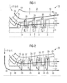
- the steam turbine 10 has a rotor 1 with a number of attached thereto Rotor or rotor blades, which in so-called Blades 3 are arranged one behind the other.
- the Blade rows 3 are rotatable in a housing 5, the has a number of rows of vane 7 and thereby along an axial extension along an axis, ie in Lengthwise extending 9.
- the rotatable blade rows 3 Grasping it like fingers in spaces between the stationary Guide vane rows 7.
- the steam turbine housing 5 is particularly preferred Embodiment of a steam turbine component according to executed the concept of the invention.
- the housing 5 could also as an inner case or as a vane carrier be formed and / or in the manner of a segmented design be formed by a number of housing segments.
- the housing 5 has an inner wall 11 and an outer wall 13 on. With the inner wall, the housing 5 defines a Flow channel 15, which receives a main flow 17 a fluid working medium is provided.
- the working medium has a changing along the longitudinal direction Flow pressure and a changing flow temperature on.
- the arranged one behind the other in the longitudinal direction Guide vane rows 7 each extend into the flow channel 15.
- the housing 5 has a flow channel 15th open in the housing 5 integrated cooling system 19 for receiving a cooling medium flow with a cooling medium pressure and a Cooling medium temperature.
- the cooling medium pressure is characterized by the decreasing pressures p 1 > p 2 > p 3 in its height.
- the flow pressure in the example explained here is characterized by the decreasing pressures P 1 > P 2 > P 3 in its sequence.
- decreasing pressures of the cooling medium and the main flow are not necessarily present in any operating condition and the pressures may be different in other examples.
- the pressures of the cooling medium could in a worse example in the limit case even as p 1 ⁇ p 2 ⁇ p 3 behave.
- the cooling system 19 shown in FIG. 1 has a main channel 23 which extends in the longitudinal direction 9 over all blade rows 3, 7.
- the cooling system also has per guide vane row 7 a branch cooling channel 25, which branches off from the main cooling channel 23 and is open to the flow channel 15.
- the housing or one or more blades on its / its surface / n an opening to the flow channel.
- the cooling system 19 has at least one reference 3 to 7 explained in detail flow resistance in the form of a throttling agent on a near-surface Throttle point, in the flow direction of the cooling medium a pressure drop of the cooling medium pressure via the throttle point set such that at the throttle point, a temperature decrease the cooling medium temperature is effected.
- a phase change from a liquid state upstream of the orifice to a vaporous state behind the throttle causes.
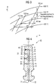
- FIG. 2 shows a further particularly preferred embodiment a high-temperature steam turbine 20, with steam as the working medium at a pressure above 250 bar and a Temperature above 540 ° C is applied or in modifications according to parameters in the "Neft" article.
- FIG 2 features of the same function with the same Named as in FIG 1, even if they are in detail in the embodiment of FIG 2 in contrast to the embodiment 1 are executed differently.
- This in particular concerns the cooling system 19 with the main cooling channel 23 and the branch cooling channels 25.
- the cooling system 19 is integrated in a rotor 31 as a special embodiment of a steam turbine component and performs essentially the same functions as the cooling system explained with reference to FIG. Accordingly, the conditions explained for the pressures p 1 > p 2 > p 3 and P 1 > P 2 > P 3 also apply in this embodiment, even if these pressures now occur at different locations.
- each pressure p is a corresponding temperature t and each pressure P is associated with a corresponding temperature T. Also for the temperatures t 1 > t 2 > t 3 and T 1 > T 2 > T 3 apply in this example.
- the rotor 31 is limited by its outer wall 33 the flow channel 15.
- the blade rows 35 in contrast to the blade rows 3 of the 1 with the cooling system 19, and in particular with the Branch cooling channels 25 designed.
- the guide blade rows 27 of Housing 29 no cooling channels.
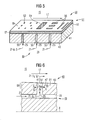
- a suitably trained cooling system be mounted in a turbine blade, as for example is shown in FIG. This can be a vane the guide vane row 7 or a blade be the blade row 3.
- an active cooling takes place the cooling by a cooling medium with, for example 500 ° C predetermined temperature t, which under the respective Temperature T of the working medium in the flow channel 15 is located.
- the cooling effect is on the temperature difference between the cooling medium temperature t and the flow temperature T limited.
- the h / s diagram is the heat absorption of the cooling medium by the isobaric change of state from the number 2 given to the numeral 3 and by a temperature difference marked according to the example shown in the amount of 75 K.
- Cooling medium Independent of the measures of the concept presented here can of course also the coolant temperature of the Cooling medium can be varied as such. This turns out, however as a comparatively more elaborate and slower Measure. Nevertheless, it could also be dependent on the cooling effect from the cooling requirements associated with a steam turbine are dependent on load and are specifically influenced.
- a change of state is shown at a second cooling location, which lies downstream of the cooling location, for which the examples explained above are shown.
- a change of state at the second cooling point leads to the state with the number 3 I - compared to the above-mentioned state with the number 3.
- Characteristic of the second cooling point is that with her the expansion of the working medium and the cooling medium has progressed further. At the second cooling point so there is a lower pressure. According to the prior art would have to go out with a by the change of state from the numeral 2 v to 3 I and I with a temperature difference of 35 K, z. B. in a cooling medium of 500 ° C, content.
- the dissipated heat flow can be above it also, of course, by the mass flow of the cooling medium determine.
- the effective differential temperature determining according to the new concept presented here thereby advantageously increased, that at the throttle point an additional temperature reduction of the cooling medium temperature t is effected.
- FIG. 4 shows a steam turbine blade 40 as a preferred Embodiment of a steam turbine component, wherein a cooling system 19 has a main cooling channel 23 extending extends in the longitudinal direction 9 of the steam turbine blade 40.
- the cooling system 19 also has a branch cooling channel 25, which branches off from the main cooling channel 23 and the flow channel 15th through an opening 46 is open.
- the flow channel 15 is for receiving a main flow 17 of a fluid working medium intended.
- the cooling system 19 serves to receive a cooling medium flow 21, wherein the cooling medium flow 21 by a cooling medium pressure p and a cooling medium temperature t as the cooling medium parameter is marked.
- Each of the branch cooling channels 25 has a flow resistance in the form of a throttle means at a near-surface throttle point 41 on.
- the throttle point 41 is within a wall 43 of the steam turbine blade 40 relative to a central surface of the wall, present in the form of the longitudinal direction 9, arranged offset to the surface 45 towards.
- the branch cooling channel 25 has a throttle means which is present in different ways is trained.
- the throttle means in the lower three throttle bodies 41 is the throttle means in the form of a waist 47 of the cooling channel 25 formed.
- the throttle means At the uppermost branch cooling channel 25 is the throttle means in the form of a surface enlarging, semipermeable Plug 49 is formed.
- the sidecut 47 So it is a cross-sectional constriction of the branch cooling channel 25 in the form of a targeted geometric constriction the clear width of the branch cooling channel 25th
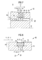
- a cooling system 19 has a main cooling channel 23 and branch cooling channels 25 for receiving a cooling medium 21st on, wherein the cooling medium by a cooling medium temperature t and a cooling medium pressure p.
- the in FIG. 5 represented part could equally well an input side Represent rotor part.
- Throttling agent in the form of a surface enlarging acting, semipermeable cladding on the surface 53 of the housing part 50 in the region of an opening 55 of the branch cooling channel 25 formed.
- the lining 51 is on the one flow channel 15 limiting surface 53 is placed, wherein the flow channel 15 for receiving a main flow 17 of a fluid working medium is provided.
- the cladding is present in two layers.
- a first layer 57 is present with a porous material in the form of a ceramic, formed.
- the second layer 59 is in Form of a cover sheet formed.
- the cover plate faces the Passage of cooling medium here exemplified openings on.
- the openings may be as shown in FIG Shape of holes 52, a network structure 54 or in the form of Columns 56 formed in any arrangement and combination be.
- Dimensions, shape and detail of the first layer 57 and the second layer 59 can be depending on the local Requirement of the cooling medium parameters p, t and the working medium parameters P, T to run at the throttle 41 a Temperature reduction of the cooling medium temperature t to cause such that at least a part of the cooling medium 21 a Phase change from a liquid state before the throttle point 41 to a vapor state behind the throttle point 41 is effected.
- FIG. 6 shows in detail a throttle means shown in FIG in the form of a sidecut 47 of a branch cooling channel 25.
- the illustrated particularly preferred embodiment of the Steam turbine component 60 has a wall 61 in its near-surface Area, the throttle body 41 is arranged. That is, the throttle 41 is relatively within the wall 61 to a central area 8 of the wall 61 to the surface 63 arranged offset.
- the throttle point 41 at a distance of not more than 50% of the component thickness arranged to the surface 63.
- the throttle body 41 is in a distance of not more than 25% of the component thickness
- Surface 63 is arranged.
- the distance can be more than 10 mm to 20 mm.
- the cooling medium 21 has in front of the throttle body 41 a cooling medium (- réelle) pressure p i and a cooling medium (- réelle) temperature t i and behind the choke point 41 a cooling medium (-Aus) pressure p a and a cooling medium (-Out) temperature t a on.
- the area near the surface 66 is to be understood as an area between the throttle point 41 of the branch cooling channel 25 and the opening 67 on the surface 63.
- the recorded enthalpy of evaporation is used for increased heat dissipation.
- the flow channel 15 is acted upon by a main flow 17 of a fluid working medium.
- the cooling system 19 is acted upon by a cooling medium flow 21 having a cooling medium pressure p and a cooling medium temperature t.
- a throttle means is at a near-surface throttle point 41 in the cooling system 19 in the direction of flow of the cooling medium 21, a pressure drop Ap of the cooling medium pressure p i -p a set via the throttle point 41 47 with at least one flow resistance in the form.
- a temperature reduction .DELTA.t the cooling medium temperature t is effected at the throttle point 41, wherein in the present example of the method for at least a portion of the cooling medium 21, a phase change from a liquid state p i , t i before the throttle body 41 to a vapor state p a , t a is effected behind the throttle 41.
- FIG. 7 again shows in detail a throttle means, as for example could be used in FIG.
- the throttle means FIG. 7 is presently in the form of a constriction 48 of FIG Branch cooling channel 25 formed, with the shown here Embodiment the constriction immediately adjacent a main cooling channel 23 continues in the branch cooling channel 25.
- the further course of the branch cooling channel 25 to the flow channel 15 results in the form of a widening 42 of the branch cooling channel 25.
- the operating principle of such a throttle means the FIG. 7 essentially corresponds to that in connection with FIG FIG 6 explained operating principle.
- the rest essential features provided with the same function of FIG 7 in comparison to FIG 6 with the same reference numerals Mistake.
- the constriction 48 exists in addition to those in connection with FIG. 6 explained advantages mainly in that present one Cooling already in the area of a branch between the main cooling channel 23 and branch cooling channel 25 can take place.
- This can, as shown in FIG 7, already in the region of a near-surface Be region 66, especially if the main cooling channel 23 is arranged relatively close to the surface.
- the embodiment shown in FIG. 7 could be the narrowing 48, however, also outside a near-surface Range, so that, if necessary, a Cooling in particular of the solid material of a steam turbine component 70 takes place.
- the cooling effect can vary depending on the absolute Dimensions of the area 66 of course to the surface 63 continue.
- the branch cooling channel 25 in the Shape shown here with a narrowing 48 and an extension 42 can namely in a particularly advantageous manner the attachment of two consecutive drilling operations be performed with different bore diameter.
- an opening 67 is first made by that a hole in the wall 61 first with a small Diameter d takes place. At the same location of the opening 67 then another hole is set. The further drilling However, it is done with a larger diameter D and the others Bore is not continued until the main cooling channel 23. Rather, the drilling depth L for a convenient Throttling of the coolant in the area of the constriction 48 each if necessary and strength of the 61 chosen.
- FIG. 8 shows a further part of a particularly preferred embodiment 80 of a steam turbine component, in which a cooling system 19 has a main cooling channel 23, not shown, and a branch cooling channel 25 with an opening 71 on the surface 73 of the embodiment 80.
- a throttle means at the near-surface throttle point 75 in the branch cooling channel 25 in the wall 76 is arranged.
- the throttle means is presently formed in the form of the opening 71 of the cooling system 19 on the surface 73.
- the opening 71 of the branch cooling channel 25 has a sidecut 77.
- the opening 71 is further provided with a semi-permeable plug 79 which is inserted into the opening 71 of the branch cooling channel 25 and fixed with locking 78.
- the plug 79 is presently formed with a close-meshed wire mesh.
- a cooling medium 21 z. B. from a cooling medium internal temperature t i in the amount of about 500 ° C to a cooling medium outside temperature t a in the amount of 475 ° C are cooled so that a temperature drop ⁇ t in the amount of 25 K results, in addition to the temperature difference between the cooling medium temperature t i and working medium temperature T for cooling the working medium in the main flow 17 is available.
- a steam turbine component 10, 20, 40, 50, 60, 70, 80 has a flow channel 15 defining surface 45, 53, 63, 73, wherein the flow channel 15 is provided for receiving a main flow 17 of a fluid working medium.
- the steam turbine component 10, 20, 40, 50, 60, 70, 80 has on its surface 45, 53, 63, 73 an opening 46, 55, 67, 71 to the flow channel 15 exhibiting, in the component 10, 20, 40, 50, 60, 70, 80 integrated cooling system 19 for receiving a cooling medium flow 21 with a cooling medium pressure p and a cooling medium temperature t.
- the cooling system 19 at least one flow resistance in the form of a throttle means at a near-surface throttle point 41, 75.
- a phase change from a liquid state p i , t i before the throttle point 41, 75 to a vapor state p a , t a behind the throttle point 41, 75 causes.
Landscapes
- Engineering & Computer Science (AREA)
- Chemical & Material Sciences (AREA)
- Combustion & Propulsion (AREA)
- Mechanical Engineering (AREA)
- General Engineering & Computer Science (AREA)
- Turbine Rotor Nozzle Sealing (AREA)
Abstract
Description
- FIG 1
- ein Dampfturbinen-Gehäuse als bevorzugte Ausführungsform einer Dampfturbinen-Komponente bei einer Hochtemperatur-Dampfturbine;
- FIG 2
- einen Dampfturbinen-Rotor als bevorzugte Ausführungsform einer Dampfturbinen-Komponente bei einer Hochtemperatur-Dampfturbine;
- FIG 3
- beispielhafte Zustandsänderungen des Kühlmediums in einem h/s-Diagramm, wobei Zustandsänderungen gemäß einer bevorzugten Ausführungsform im Vergleich zum Stand der Technik nebeneinander gestellt sind;
- FIG 4
- eine bevorzugte Ausführungsform einer Dampfturbinen-Komponente in Form einer Dampfturbinen-Schaufel;
- FIG 5
- ein Drosselmittel in Form einer halbdurchlässigen Verkleidung im Bereich der Öffnung zum Strömungskanal auf der Oberfläche einer bevorzugten Ausführungsform einer Dampfturbinen-Komponente in Form eines Dampfturbinen-Gehäuses oder eines Dampfturbinen-Rotors;
- FIG 6
- ein anderes Drosselmittel in Form einer Taillierung der Öffnung eines Kühlkanals bei einer bevorzugten Ausführungsform einer Dampfturbinen-Komponente;
- FIG 7
- ein anderes Drosselmittel in Form einer Verengung eines Zweigkühlkanals an der Stelle der Abzweigung von einem Hauptkühlkanal;
- FIG 8
- ein anderes Drosselmittel in Form eines halbdurchlässigen Stopfens in der Öffnung eines Kühlkanals bei einer bevorzugten Ausführungsform einer Dampfturbinen-Komponente.
Claims (26)
- Dampfturbinen-Komponente (10, 20, 40, 50, 60, 70, 80), die eine einen Strömungskanal (15) begrenzende Oberfläche (45, 53, 63, 73) aufweist, wobei der Strömungskanal (15) zur Aufnahme einer Hauptströmung (17) eines fluiden Arbeitsmediums vorgesehen ist,
und die ein an ihrer Oberfläche (45, 53, 63, 73) eine Öffnung (46, 55, 67, 71) zum Strömungskanal (15) aufweisendes Kühlsystem (19) zur Aufnahme einer Kühlmediumströmung (21) mit einem Kühlmediumdruck (p) und einer Kühlmediumtemperatur (t) aufweist,
dadurch gekennzeichnet, dass
das Kühlsystem (19) wenigstens einen Strömungswiderstand in Form eines Drosselmittels an einer Drosselstelle (41, 75) aufweist,
das in Strömungsrichtung des Kühlmediums einen Druckabfall (Δp = pa - pi) des Kühlmediumdruckes (p) über die Drosselstelle (41, 75) derart einstellt,
dass an der Drosselstelle (41, 75) eine Temperaturabsenkung (Δt = ta - ti) der Kühlmediumtemperatur (t) bewirkt ist. - Dampfturbinen-Komponente (10, 20, 40, 50, 60, 70, 80) nach Anspruch 1,
dadurch gekennzeichnet, dass
bei wenigstens einem Teil des Kühlmediums ein Phasenwechsel von einem flüssigen Zustand (pi, ti) vor der Drosselstelle (41, 75) zu einem dampfförmigen Zustand (pa, ta) hinter der Drosselstelle (41, 75) bewirkt ist. - Dampfturbinen-Komponente (10, 20, 40, 50, 60, 70, 80) nach Anspruch 1 oder 2,
dadurch gekennzeichnet, dass
die Drosselstelle (41, 75) an einer Wand (43, 61) der Komponente (60, 70) relativ zu einer Mittelfläche (8) der Wand (43, 61) zur Oberfläche (45, 53, 63, 73) hin versetzt angeordnet ist. - Dampfturbinen-Komponente (40, 50, 60, 70, 80) nach einem der Ansprüche 1 bis 3 in Form einer Dampfturbinen-Schaufel (40).
- Dampfturbinen-Komponente (10, 20, 50, 60, 70, 80) nach einem der Ansprüche 1 bis 3,
dadurch gekennzeichnet, dass
die Komponente (10, 20, 50, 60, 70) eine Anzahl von, mehrere Schaufeln aufweisende, in Längsrichtung (9) hintereinander angeordnete Schaufelstufen (7, 35) trägt, die sich jeweils in den Strömungskanal (15) erstrecken. - Dampfturbinen-Komponente (10, 20, 50, 60, 70, 80) nach Anspruch 5 in Form eines Dampfturbinen-Rotors (31).
- Dampfturbinen-Komponente (10, 20, 50, 60, 70) nach Anspruch 5 in Form eines Dampfturbinen-Gehäuses (5).
- Dampfturbinen-Komponente (10, 20, 40, 50, 60, 70, 80) nach einem der Ansprüche 1 bis 7,
dadurch gekennzeichnet, dass
das Kühlsystem (19) einen Hauptkühlkanal (23) aufweist, der sich in Längsrichtung (9) der Komponente (10, 20, 40, 50, 60, 70, 80) erstreckt, und
das einen Zweigkühlkanal (25) aufweist, der vom Hauptkühlkanal (23) abzweigt und zum Strömungskanal (15) offen ist. - Dampfturbinen-Komponente (10, 20, 50, 60, 70, 80) nach einem der Ansprüche 5 bis 8,
dadurch gekennzeichnet, dass
sich ein Hauptkühlkanal (23) über eine Ausdehnung wenigstens einer Schaufelreihe (3, 7, 27, 35) erstreckt. - Dampfturbinen-Komponente (10, 20, 50, 60, 70) nach Anspruch 9,
dadurch gekennzeichnet, dass
ein Zweigkühlkanal (25) einen eine Schaufelreihe (3, 7, 27, 35) umgebenden Ringkanal aufweist. - Dampfturbinen-Komponente (10, 20, 50, 60, 70, 80) nach Anspruch 9 oder 10,
dadurch gekennzeichnet, dass
der Zweigkühlkanal (25) eine oder mehrere von einem Ringkanal ausgehende Schaufelkanäle aufweist, die in eine oder eine Anzahl oder alle Schaufeln einer Schaufelreihe (3, 7, 27, 35) führen. - Dampfturbinen-Komponente (10, 20, 40, 50, 60, 70, 80) nach einem der Ansprüche 8 bis 11,
dadurch gekennzeichnet, dass
das Drosselmittel an einer, insbesondere oberflächennahen, Drosselstelle (41, 75) in einem Hauptkühlkanal (23) angeordnet ist. - Dampfturbinen-Komponente (10, 20, 40, 50, 60, 70, 80) nach einem der Ansprüche 8 bis 12,
dadurch gekennzeichnet, dass
das Drosselmittel an einer, insbesondere oberflächennahen, Drosselstelle (41, 75) in einem Zweigkühlkanal (25) angeordnet ist. - Dampfturbinen-Komponente (10, 20, 50, 60, 70, 80) nach Anspruch 9 oder 10,
dadurch gekennzeichnet, dass
das Drosselmittel an einer, insbesondere oberflächennahen, Drosselstelle (41, 75) in einem Ringkanal angeordnet ist. - Dampfturbinen-Komponente (10, 20, 40, 50, 60, 70, 80) nach einem der Ansprüche 8 bis 14,
dadurch gekennzeichnet, dass
das Drosselmittel an einer, insbesondere oberflächennahen, Drosselstelle (41, 75) in einem Schaufelkanal angeordnet ist. - Dampfturbinen-Komponente (10, 20, 40, 50, 60, 70, 80) nach einem der Ansprüche 1 bis 15,
dadurch gekennzeichnet, dass
das Drosselmittel eine geometrisch feste Form aufweist. - Dampfturbinen-Komponente (10, 20, 40, 50, 60, 70, 80) nach einem der Ansprüche 1 bis 16,
dadurch gekennzeichnet, dass
das Drosselmittel in Form der Öffnung (71) des Kühlsystems (19) gebildet ist. - Dampfturbinen-Komponente (10, 20, 40, 60, 70, 80) nach einem der Ansprüche 1 bis 17,
dadurch gekennzeichnet, dass
das Drosselmittel in Form einer Taillierung (47, 77) eines Kühlkanals (23, 25) und/oder der Öffnung (71) des Kühlsystems (19) gebildet ist. - Dampfturbinen-Komponente (10, 20, 40, 70, 80) nach einem der Ansprüche 1 bis 18,
dadurch gekennzeichnet, dass
das Drosselmittel in Form eines halbdurchlässigen Stopfens (49, 79) in einem Kühlkanal (23, 25) und/oder der Öffnung (46, 71) des Kühlsystems (19) gebildet ist. - Dampfturbinen-Komponente (10, 20, 50, 80) nach einem der Ansprüche 1 bis 19,
dadurch gekennzeichnet, dass
das Drosselmittel in Form einer halbdurchlässigen Verkleidung (51) im Bereich der Öffnung (55) zum Strömungskanal (15) auf der Oberfläche (53) der Komponente (50) gebildet ist. - Dampfturbine (10, 20), insbesondere Hochtemperatur-Dampfturbine (10, 20), mit einer Dampfturbinen-Komponente (40, 50, 60, 70) nach einem der vorhergehenden Ansprüche.
- Verfahren zum Kühlen einer Dampfturbine (10, 20) gemäß Anspruch 21,
wobeidadurch gekennzeichnet, dassder Strömungskanal (15) mit einer Hauptströmung (17) eines fluiden Arbeitsmediums beaufschlagt wird, unddas Kühlsystem (15) mit einer Kühlmediumströmung (21), mit einem Kühlmediumdruck (p) und einer Kühlmediumtemperatur (t), beaufschlagt wird,
mit wenigstens einem Strömungswiderstand in Form eines Drosselmittels an einer Drosselstelle (41, 75) im Kühlsystem (19),
in Strömungsrichtung des Kühlmediums ein Druckabfall
(Δp = pa - pi) des Kühlmediumdruckes (p) über die Drosselstelle (41, 75) eingestellt wird, und an der Drosselstelle (41, 75) eine Temperaturabsenkung (Δt = ta - ti) der Kühlmediumtemperatur (t) bewirkt wird. - Verfahren gemäß Anspruch 22, wobei
für wenigstens einen Teil des Kühlmediums ein Phasenwechsel von einem flüssigen Zustand (pi, ti) vor der Drosselstelle (41, 75) zu einem dampfförmigen (pa, ta) Zustand hinter der Drosselstelle (41, 75) bewirkt wird. - Verfahren gemäß Anspruch 22 oder 23, wobei
der Kühlmediumdruck (p) im Kühlsystem mittels wenigstens einem weiteren Strömungswiderstand über einem Strömungsdruck (P) der Hauptströmung (17) gehalten wird. - Verwendung eines Drosselmittels an einer Drosselstelle (41, 75) als Strömungswiderstand im Kühlsystem (19) einer Dampfturbine (10, 20) nach Anspruch 21, um bei Betrieb der Dampfturbine (10, 20) in Strömungsrichtung des Kühlmediums mit einem Kühlmediumdruck (p) und einer Kühlmediumtemperatur (t) einen Druckabfall (Δp = pa - pi) des Kühlmediumdruckes (p) über die Drosselstelle (41, 75) derart einzustellen, dass an der Drosselstelle (41, 75) eine Temperaturabsenkung (Δt = ta - ti) der Kühlmediumtemperatur (t) bewirkt wird.
- Verwendung nach Anspruch 25,
bei der für wenigstens einen Teil des Kühlmediums ein Phasenwechsel von einem flüssigen Zustand (pi, ti) vor der Drosselstelle (41, 75) zu einem dampfförmigen Zustand (pa, ta) hinter der Drosselstelle (41, 75) bewirkt wird.
Priority Applications (2)
| Application Number | Priority Date | Filing Date | Title |
|---|---|---|---|
| EP04012135A EP1598522B1 (de) | 2004-05-21 | 2004-05-21 | Dampfturbinen-Komponente und Verfahren zum Kühlen einer Dampfturbine sowie Verwendung |
| DE200450004290 DE502004004290D1 (de) | 2004-05-21 | 2004-05-21 | Dampfturbinen-Komponente und Verfahren zum Kühlen einer Dampfturbine sowie Verwendung |
Applications Claiming Priority (1)
| Application Number | Priority Date | Filing Date | Title |
|---|---|---|---|
| EP04012135A EP1598522B1 (de) | 2004-05-21 | 2004-05-21 | Dampfturbinen-Komponente und Verfahren zum Kühlen einer Dampfturbine sowie Verwendung |
Publications (2)
| Publication Number | Publication Date |
|---|---|
| EP1598522A1 true EP1598522A1 (de) | 2005-11-23 |
| EP1598522B1 EP1598522B1 (de) | 2007-07-11 |
Family
ID=34925082
Family Applications (1)
| Application Number | Title | Priority Date | Filing Date |
|---|---|---|---|
| EP04012135A Expired - Lifetime EP1598522B1 (de) | 2004-05-21 | 2004-05-21 | Dampfturbinen-Komponente und Verfahren zum Kühlen einer Dampfturbine sowie Verwendung |
Country Status (2)
| Country | Link |
|---|---|
| EP (1) | EP1598522B1 (de) |
| DE (1) | DE502004004290D1 (de) |
Cited By (3)
| Publication number | Priority date | Publication date | Assignee | Title |
|---|---|---|---|---|
| DE102009037411A1 (de) * | 2009-08-13 | 2011-05-26 | Siemens Aktiengesellschaft | Erosionsschutzvorrichtung für Dampfturbinenstufen |
| EP3266982A1 (de) * | 2016-07-06 | 2018-01-10 | Siemens Aktiengesellschaft | Turbinenschaufel mit kühlmittelkanal und auslassöffnung |
| US10683763B2 (en) | 2016-10-04 | 2020-06-16 | Honeywell International Inc. | Turbine blade with integral flow meter |
Citations (2)
| Publication number | Priority date | Publication date | Assignee | Title |
|---|---|---|---|---|
| DE1056426B (de) * | 1951-05-16 | 1959-04-30 | Power Jets Res & Dev Ltd | Kuehleinrichtung an Gasturbinenanlagen |
| JPH06193408A (ja) * | 1992-12-24 | 1994-07-12 | Hitachi Ltd | 蒸気タービンの排気室過熱防止装置 |
-
2004
- 2004-05-21 DE DE200450004290 patent/DE502004004290D1/de not_active Expired - Lifetime
- 2004-05-21 EP EP04012135A patent/EP1598522B1/de not_active Expired - Lifetime
Patent Citations (2)
| Publication number | Priority date | Publication date | Assignee | Title |
|---|---|---|---|---|
| DE1056426B (de) * | 1951-05-16 | 1959-04-30 | Power Jets Res & Dev Ltd | Kuehleinrichtung an Gasturbinenanlagen |
| JPH06193408A (ja) * | 1992-12-24 | 1994-07-12 | Hitachi Ltd | 蒸気タービンの排気室過熱防止装置 |
Non-Patent Citations (1)
| Title |
|---|
| PATENT ABSTRACTS OF JAPAN vol. 018, no. 548 (M - 1689) 19 October 1994 (1994-10-19) * |
Cited By (5)
| Publication number | Priority date | Publication date | Assignee | Title |
|---|---|---|---|---|
| DE102009037411A1 (de) * | 2009-08-13 | 2011-05-26 | Siemens Aktiengesellschaft | Erosionsschutzvorrichtung für Dampfturbinenstufen |
| DE102009037411B4 (de) | 2009-08-13 | 2014-08-21 | Siemens Aktiengesellschaft | Erosionsschutzvorrichtung für Dampfturbinenstufen |
| EP3266982A1 (de) * | 2016-07-06 | 2018-01-10 | Siemens Aktiengesellschaft | Turbinenschaufel mit kühlmittelkanal und auslassöffnung |
| WO2018007274A1 (de) * | 2016-07-06 | 2018-01-11 | Siemens Aktiengesellschaft | Turbinenschaufel mit kühlmittelkanal und auslassöffnung |
| US10683763B2 (en) | 2016-10-04 | 2020-06-16 | Honeywell International Inc. | Turbine blade with integral flow meter |
Also Published As
| Publication number | Publication date |
|---|---|
| EP1598522B1 (de) | 2007-07-11 |
| DE502004004290D1 (de) | 2007-08-23 |
Similar Documents
| Publication | Publication Date | Title |
|---|---|---|
| EP2423599B1 (de) | Verfahren zum Betrieb einer Brenneranordnung sowie Brenneranordnung zur Durchführung des Verfahrens | |
| EP1452688A1 (de) | Dampfturbinenrotor sowie Verfahren und Verwendung einer aktiven Kühlung eines Dampfturbinenrotors | |
| DE2622234C2 (de) | Vorrichtung zur Zuführung von Kühlluft in das Flammrohr von Gasturbinen-Brennkammern | |
| EP1505254B1 (de) | Gasturbine und zugehöriges Kühlverfahren | |
| DE69411301T2 (de) | Gasturbine und Verfahren zur Montage einer Dichtung in dieser Gasturbine | |
| DE68906779T2 (de) | Spielkontrollvorrichtung fuer die schaufelspitzen einer gasturbine. | |
| CH642428A5 (de) | Abdeckanordnung in einer turbine. | |
| DE102014100482A1 (de) | Heißgaspfadbauteil für Turbinensystem | |
| CH702540A2 (de) | System zur Einstellung der Luftmenge in einer Gasturbine mit einem temperaturaktivierten Ventil. | |
| DE2907748A1 (de) | Einrichtung zur minimierung und konstanthaltung der bei axialturbinen vorhandenen schaufelspitzenspiele, insbesondere fuer gasturbinentriebwerke | |
| EP1409926B1 (de) | Prallkühlvorrichtung | |
| EP2815083A1 (de) | Bauteil für eine thermische maschine, insbesondere eine gasturbine | |
| DE102017110051A1 (de) | Schaufel mit belastungsreduzierendem bauchigem Vorsprung an einer Wendeöffnung von Kühlmittelkanälen | |
| DE102017110055A1 (de) | Zentraler Zwischenkanal, der äußere Wände hinter einem Vorderkantenkanal eines Schaufelblattes überbrückt | |
| EP2730844B1 (de) | Brennkammerschindel einer Gasturbine sowie Verfahren zu deren Herstellung | |
| EP1165942B1 (de) | Strömungsmaschine mit einer kühlbaren anordnung von wandelementen und verfahren zur kühlung einer anordnung von wandelementen | |
| DE2127454A1 (de) | Gasturbine | |
| EP3263838A1 (de) | Turbinenschaufel mit innerem kühlkanal | |
| EP3155226B1 (de) | Dampfturbine und verfahren zum betrieb einer dampfturbine | |
| EP1445427A1 (de) | Dampfturbine und Verfahren zum Betreiben einer Dampfturbine | |
| EP2347101B1 (de) | Gasturbine und zugehörige Gas- bzw. Dampfturbinenanlage | |
| EP1598522B1 (de) | Dampfturbinen-Komponente und Verfahren zum Kühlen einer Dampfturbine sowie Verwendung | |
| EP2347100B1 (de) | Gasturbine mit kühleinsatz | |
| DE112014006619B4 (de) | Gasturbinenbrennkammer und mit selbiger versehene Gasturbine | |
| DE10037776A1 (de) | Brennkammer für ein Flüssigkeitsraketentriebwerk |
Legal Events
| Date | Code | Title | Description |
|---|---|---|---|
| PUAI | Public reference made under article 153(3) epc to a published international application that has entered the european phase |
Free format text: ORIGINAL CODE: 0009012 |
|
| AK | Designated contracting states |
Kind code of ref document: A1 Designated state(s): AT BE BG CH CY CZ DE DK EE ES FI FR GB GR HU IE IT LI LU MC NL PL PT RO SE SI SK TR |
|
| AX | Request for extension of the european patent |
Extension state: AL HR LT LV MK |
|
| 17P | Request for examination filed |
Effective date: 20051219 |
|
| 17Q | First examination report despatched |
Effective date: 20060207 |
|
| AKX | Designation fees paid |
Designated state(s): CH DE GB IT LI |
|
| GRAP | Despatch of communication of intention to grant a patent |
Free format text: ORIGINAL CODE: EPIDOSNIGR1 |
|
| GRAS | Grant fee paid |
Free format text: ORIGINAL CODE: EPIDOSNIGR3 |
|
| GRAA | (expected) grant |
Free format text: ORIGINAL CODE: 0009210 |
|
| AK | Designated contracting states |
Kind code of ref document: B1 Designated state(s): CH DE GB IT LI |
|
| REG | Reference to a national code |
Ref country code: GB Ref legal event code: FG4D Free format text: NOT ENGLISH |
|
| REG | Reference to a national code |
Ref country code: CH Ref legal event code: NV Representative=s name: SIEMENS SCHWEIZ AG Ref country code: CH Ref legal event code: EP |
|
| GBT | Gb: translation of ep patent filed (gb section 77(6)(a)/1977) |
Effective date: 20070727 |
|
| REF | Corresponds to: |
Ref document number: 502004004290 Country of ref document: DE Date of ref document: 20070823 Kind code of ref document: P |
|
| PLBE | No opposition filed within time limit |
Free format text: ORIGINAL CODE: 0009261 |
|
| STAA | Information on the status of an ep patent application or granted ep patent |
Free format text: STATUS: NO OPPOSITION FILED WITHIN TIME LIMIT |
|
| 26N | No opposition filed |
Effective date: 20080414 |
|
| REG | Reference to a national code |
Ref country code: CH Ref legal event code: PCAR Free format text: SIEMENS SCHWEIZ AG;INTELLECTUAL PROPERTY FREILAGERSTRASSE 40;8047 ZUERICH (CH) |
|
| PGFP | Annual fee paid to national office [announced via postgrant information from national office to epo] |
Ref country code: GB Payment date: 20160512 Year of fee payment: 13 |
|
| PGFP | Annual fee paid to national office [announced via postgrant information from national office to epo] |
Ref country code: IT Payment date: 20160527 Year of fee payment: 13 |
|
| PGFP | Annual fee paid to national office [announced via postgrant information from national office to epo] |
Ref country code: CH Payment date: 20160802 Year of fee payment: 13 Ref country code: DE Payment date: 20160720 Year of fee payment: 13 |
|
| REG | Reference to a national code |
Ref country code: CH Ref legal event code: PCOW Free format text: NEW ADDRESS: WERNER-VON-SIEMENS-STRASSE 1, 80333 MUENCHEN (DE) |
|
| REG | Reference to a national code |
Ref country code: DE Ref legal event code: R119 Ref document number: 502004004290 Country of ref document: DE |
|
| REG | Reference to a national code |
Ref country code: CH Ref legal event code: PL |
|
| GBPC | Gb: european patent ceased through non-payment of renewal fee |
Effective date: 20170521 |
|
| PG25 | Lapsed in a contracting state [announced via postgrant information from national office to epo] |
Ref country code: CH Free format text: LAPSE BECAUSE OF NON-PAYMENT OF DUE FEES Effective date: 20170531 Ref country code: LI Free format text: LAPSE BECAUSE OF NON-PAYMENT OF DUE FEES Effective date: 20170531 |
|
| PG25 | Lapsed in a contracting state [announced via postgrant information from national office to epo] |
Ref country code: GB Free format text: LAPSE BECAUSE OF NON-PAYMENT OF DUE FEES Effective date: 20170521 Ref country code: DE Free format text: LAPSE BECAUSE OF NON-PAYMENT OF DUE FEES Effective date: 20171201 |
|
| PG25 | Lapsed in a contracting state [announced via postgrant information from national office to epo] |
Ref country code: IT Free format text: LAPSE BECAUSE OF NON-PAYMENT OF DUE FEES Effective date: 20170521 |