EP1598508A1 - Mehrpunktverriegelungsvorrichtung für Schiebetüren - Google Patents
Mehrpunktverriegelungsvorrichtung für Schiebetüren Download PDFInfo
- Publication number
- EP1598508A1 EP1598508A1 EP05386013A EP05386013A EP1598508A1 EP 1598508 A1 EP1598508 A1 EP 1598508A1 EP 05386013 A EP05386013 A EP 05386013A EP 05386013 A EP05386013 A EP 05386013A EP 1598508 A1 EP1598508 A1 EP 1598508A1
- Authority
- EP
- European Patent Office
- Prior art keywords
- bar
- latching assembly
- profile member
- sliding
- latch means
- Prior art date
- Legal status (The legal status is an assumption and is not a legal conclusion. Google has not performed a legal analysis and makes no representation as to the accuracy of the status listed.)
- Granted
Links
- 230000000087 stabilizing effect Effects 0.000 claims description 12
- 230000007246 mechanism Effects 0.000 claims description 8
- 238000000034 method Methods 0.000 claims description 6
- 238000009434 installation Methods 0.000 claims description 5
- 230000009471 action Effects 0.000 claims description 3
- 230000008569 process Effects 0.000 claims description 3
- 230000003213 activating effect Effects 0.000 claims description 2
- 230000006835 compression Effects 0.000 claims description 2
- 238000007906 compression Methods 0.000 claims description 2
- 230000002401 inhibitory effect Effects 0.000 claims description 2
- 230000000712 assembly Effects 0.000 description 4
- 238000000429 assembly Methods 0.000 description 4
- 230000000977 initiatory effect Effects 0.000 description 2
- 230000004913 activation Effects 0.000 description 1
- 230000003247 decreasing effect Effects 0.000 description 1
- 230000000694 effects Effects 0.000 description 1
- 230000002708 enhancing effect Effects 0.000 description 1
- 238000004519 manufacturing process Methods 0.000 description 1
- 239000000463 material Substances 0.000 description 1
- 239000002184 metal Substances 0.000 description 1
- 230000004048 modification Effects 0.000 description 1
- 238000012986 modification Methods 0.000 description 1
- 230000001360 synchronised effect Effects 0.000 description 1
Images


Classifications
-
- E—FIXED CONSTRUCTIONS
- E05—LOCKS; KEYS; WINDOW OR DOOR FITTINGS; SAFES
- E05C—BOLTS OR FASTENING DEVICES FOR WINGS, SPECIALLY FOR DOORS OR WINDOWS
- E05C9/00—Arrangements of simultaneously actuated bolts or other securing devices at well-separated positions on the same wing
- E05C9/18—Details of fastening means or of fixed retaining means for the ends of bars
-
- E—FIXED CONSTRUCTIONS
- E05—LOCKS; KEYS; WINDOW OR DOOR FITTINGS; SAFES
- E05C—BOLTS OR FASTENING DEVICES FOR WINGS, SPECIALLY FOR DOORS OR WINDOWS
- E05C9/00—Arrangements of simultaneously actuated bolts or other securing devices at well-separated positions on the same wing
- E05C9/006—Details of bars
-
- E—FIXED CONSTRUCTIONS
- E05—LOCKS; KEYS; WINDOW OR DOOR FITTINGS; SAFES
- E05C—BOLTS OR FASTENING DEVICES FOR WINGS, SPECIALLY FOR DOORS OR WINDOWS
- E05C9/00—Arrangements of simultaneously actuated bolts or other securing devices at well-separated positions on the same wing
- E05C9/18—Details of fastening means or of fixed retaining means for the ends of bars
- E05C9/1825—Fastening means
- E05C9/1833—Fastening means performing sliding movements
- E05C9/185—Fastening means performing sliding movements parallel with actuating bar
-
- E—FIXED CONSTRUCTIONS
- E05—LOCKS; KEYS; WINDOW OR DOOR FITTINGS; SAFES
- E05B—LOCKS; ACCESSORIES THEREFOR; HANDCUFFS
- E05B65/00—Locks or fastenings for special use
- E05B65/08—Locks or fastenings for special use for sliding wings
Definitions
- the invention relates to the field of the art of locksmith and in particular refers to locking means of sliding door or window panels and discloses a multipoint latching assembly comprising a pair of cooperatively employed longitudinally extending abutting bars, one of which is fixedly mounted at a plurality of points within the sliding profile member and the other is provided with a plurality of latch means and performs a reciprocating movement thereby accordingly setting the multipoint latching assembly at a locked or unlocked condition.
- Sliding door/window panels of the prior art conventionally employ a single locking point with a locking operation handle means being mounted onto the sliding panel and used in activating a locking means, such as a hook, a pin, etc. that engages into a correspondingly formed receiving member being fixedly mounted onto the vertically extending length of the frame profile member.
- a locking means such as a hook, a pin, etc. that engages into a correspondingly formed receiving member being fixedly mounted onto the vertically extending length of the frame profile member.
- Such single locking point might be violated by burglars with a small or greater effort, depending on the specific technology and quality of manufacturing thereof. It is for this reason that pivotally mounted windows have for some time introduced multipoint locking assemblies that may provide an enhanced protection against burglars.
- Such assemblies comprise sequentially engaged bars with a plurality of locking members attached thereupon, wherein such bars may be set into a synchronized linear movement through the locking operation handle means of the device.
- sliding door / window panels have not so far employed corresponding multipoint locking assemblies and this leads, nowadays with the ever increasing burglar activity, to a decreased demand thereof by the consumers.
- Another object of the invention in view of implementation of the above main object thereof is the disclosure of a pair of longitudinally extending bars having a width such as to freely enter through a frontal opening of the sliding profile member, said bars having a length such as to cover a desirable portion or even the entire length of the vertically extending sliding profile member, wherein the first bar is fixedly mounted by means of a plurality of supporting blocks and bolts passing through both bars and the supporting blocks, said bolts being screwed until they abut onto an interior lateral wall of the sliding profile member, whereby a pair of side extensions of each one of the supporting blocks abut onto frontal lateral side walls of the sliding profile member thereby providing a counter support, and wherein the second bar is provided with a plurality of latch means passing through slots of the abovementioned first bar, said second bar performing a reciprocating movement thereby displacing the plurality of latch means along the abovementioned slots of the first bar in order to engage into a corresponding plurality of receiving members being fixedly mounted along the oppos
- Another object of the invention is, in view of averting the possibility of a deformation or fracture of the latch means and/or of the receiving members if the case arises of the sliding panel being led to closure with the latch means set at locked condition and thereby colliding onto the protruding respective receiving members, to disclose an automatic retraction capacity of the second bar being provided with the latch means during such unsuitable closure action with a scope of ensuring protection of the latch means and/or receiving members from undesirable damage.
- Another object of the invention in view of satisfying the above mentioned object of automatic retraction of the second bar being provided with the latch means of the invention thereby averting damage of latch means and/or receiving members thereof, is to disclose an advantageous multipoint connection of the abovementioned first and second bars by means of a plurality of pin-spring assemblies, said pins protruding marginally forward of the latch means so as to be the first to coll ide onto the vertically extending length of the frame profile member in case of an unsuitable closure action, thereby initiating a retraction of the bar bearing the latch means and ensuring protection of latch means and/or receiving members of the latching assembly of the invention.
- Another object of the invention is to provide the herein proposed multipoint latching assembly with the alternative options of either installing it on a sliding panel that is equipped with a typical commercially available lock means whereby the first and second bars are provided with suitable openings to allow passage of bolt means to connect with the mechanism of such commercially available lock means or installing the same on a sliding panel without any other lock means whereby an independent handle means passes through an opening of a side wall of the sliding panel and is connected into the interior second bar bearing the latch means of the invention.
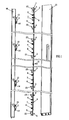
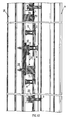
- the multipoint latching assembly for sliding doors of the invention comprises a pair of cooperatively employed longitudinally extending bars 1 and 2, which as long as the assembly is in normal operation, - either in a locked condition with the latch means engaged into the receiving members (Fig. 11) or an unlocked condition with the latch means released from the receiving members (Fig. 12), - abut onto one another, however being linked in such a manner that the second bar 2 may automatically retract in relation to the fixedly mounted bar 1 (Fig. 13) in case of an undesired collision of the sliding profile member 15 onto the frame profile member 16 with the latching assembly at a locked condition.
- Bars 1, 2 are cut at a desired length that represents a portion that might correspond even to approximately the entire length of the vertically extending extruded sliding profile member 15 within which they will be mounted. As shown in Fig. 3, bars 1, 2 correspondingly include:
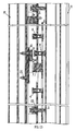
- the hereinabove described multipoint latching assembly of the invention includes a plurality of latch means receiving members 11 fixedly mounted onto the vertically extending length of the frame profile member 16, one receiving member 11 for each one of the latch means 7 welded along bar 2 and protruding through the elongated slots 7a of the fixedly mounted bar 1.
- latch means 7 comprises a main body 17a with a generally thin rectilinear configuration of dimensions such as to pass through slots 7a of bar 1, extending into a bottom pair of legs 17c being expanded during the riveting process of fixedly securing latch means 7 onto the sequentially arranged plurality of points 7b along movable bar 2.
- the top of main body 17a of latch means 7 is a rectilinear enlarged head 17b that enters into a channel of the receiving member 11 and becomes encaged therein because of the inwardly bent side flanges 11 a thereof.
- each receiving member 11 is a rectangular plate provided with a pair of end openings 11b receiving a corresponding pair of bolts 14 by means of which the receiving member 11 is fixedly mounted onto the vertically extending length of the frame profile member 16.
- a pair of inwardly bent side flanges 11a of the receiving member 11 forms a channel for inserting through sliding latch means 7 and in particular of the rectilinear enlarged head 17b thereof and subsequently encaging the same therein.
- an additional plate 12 of similar rectangular section can be employed.
- Plate 12 is provided with a pair of upper and lower openings 12b, axially coincident with openings 11b of the rectangular plate 11 of the receiving member, sequentially receiving the same abovementioned pair of bolts 14.
- Plate 12 is marginally longer than plate 11 of the receiving member and extends into parallel upper and lower protrusions 12a intermediately of which is received the receiving member plate 11.
- terminal stop members are used, preferably one at the top and another at the bottom of the vertically extending abutting sliding and frame profile members.
- Each terminal stop member as illustratively shown in Fig.
- each one of the herein proposed receiving members for the latch means of the invention further comprises an independent terminal stop member 13 ensuring engagement of the latch means 7 within the channel being formed by the inwardly bent side flanges 11a and inhibiting release of latch means 7 from the receiving member 11 that might be attempted by upwardly raising the sliding panel.
- the terminal stop member 13 has a rectangular section and extends to a bottom leg 13a that fits within the channel being formed by the inwardly bent flanges 11a of the receiving member and includes an opening 13b whereby a bolt 14 passing through this opening 13b and coincident opening 11b of the receiving member fixedly attaches the terminal stop member 13 onto the receiving member.
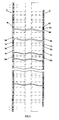
- connection of the pair of abutting bars 1 and 2 of the multipoint latching assembly of the invention is being performed on the one hand by means of bolts 3 that accordingly pass through supporting blocks 23 by means of which bar 1 is fixedly mounted against the walls of the sliding profile member and on the other hand by means of the connection means providing the advantageous automatic retraction of bar 2 from bar 1 to inhibit potential damage of protruding latch means due to undesirable collision of the sliding panel onto the fixed frame profile member, wherein bar 2 automatically returns into a condition of abutment onto bar 1 after the abovementioned undesirable collision and return of the multipoint latching assembly at an unlocked condition.
- each supporting block 23 comprises a pair of elevated side extensions 23a symmetrically extending on either side of a central opening 23b through which passes the abovementioned bolt 3 and a central recession 23c on the basement thereof.
- Different sliding profile series may employ supporting blocks 23 with slight variations in the configuration and dimensions thereof.
- the width of supporting blocks 23, as well as the length of the central recession 23c at the basement thereof corresponds to the width of abutting bars 1 and 2 of the multipoint latching assembly, so that the width of supporting blocks 23 does not surpass the width of bars 1 and 2 when such blocks extend linearly along bars 1 and 2, whilst being capable of providing a matching recession of fixedly mounted bar 1 within the recessions 23c at the basement thereof, as supporting blocks 23 are turned at the position of fixedly mounting thereof extending perpendicularly to the abutting bars 1, 2.
- the novel method of installation of the multipoint latching assembly the invention comprises a first step of assembling the multipoint latching assembly with a plurality of supporting blocks 23 mounted along the abutting bars 1 and 2, so that bolts 3 may sequentially pass through the central openings 23b of the supporting blocks, through the internally threaded openings 3a of bar 1 and through the slots 3b of bar 2, a second step of longitudinal alignment of supporting blocks 23 along abutting bars 1 and 2 so that the assembly of abutting bars 1, 2 and supporting blocks 23 mounted thereupon might be freely inserted through a frontal opening 15c of the sliding profile member 15, a third step comprising a 90° rotation of each one of the supporting blocks 23 so that they may extend perpendicularly onto the abutting bars 1, 2 (Fig.
- the installation of the multipoint locking assembly of the invention is completed with the installation of a plurality of latch means receiving members 11 onto the vertically extending length of the frame profile member 16, opposite to the sliding profile member 15, each receiving member 11 comprising incorporated additional plate 12 and terminal stop member 13.
- the number and spacing of receiving members 11 is determined by the number and spacing of the latch means 7 of the multipoint latching assembly protruding through the frontal opening 15c of the sliding profile member 1.
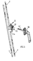
- the multipoint latching assembly of the invention can be connected to a locking operation handle means already installed onto the sliding profile member, whereby as shown in Fig. 4, a bolt 10 is employed instead of the bolt lock of the locking operation assembly, said bolt 10 sequentially passing through a slot 10a of the frontal fixedly mounted bar 1 and through an opening 10b of the movable rear bar 2 and ending up into being screwed into the mechanism of the locking assembly. Subsequently all latch means 7 mounted onto the multipoint latching assembly of the invention might be alternatively set at a locked or unlocked condition through clockwise or anticlockwise rotation of locking handle means 4a that results in a corresponding upward or downward movement of the movable bar 2 bearing the latch means 7.
- the multipoint latching assembly as shown in Fig. 5 comprises a self operating handle means 4b and in this case the movable bar 2 comprises a mechanism 20 being mounted by means of rivets 21 passing through openings 21a of bar 2, whereby a shaft means 4b' of the rotatable handle means 4b passes through an opening in the frontal wall of sliding profile member 15 (not shown) to be connected into a central opening 20a of mechanism 20, whereby as handle means 4b rotates, such rotational movement is converted into linear reciprocating movement of bar 2 by means of mechanism 20 and the plurality of latch means 7 are simultaneously set in a locked or unlocked condition correspondingly into the receiving members 11 being installed along the fixed frame profile member 16 by means of a single clockwise or counterclockwise rotation of handle means 4b respectively.
- abutting bars 1 and 2 are also being connected by means of a plurality of connection means providing the advantageous automatic retraction of bar 2 from bar 1 as shown in Fig. 13, thereby averting damage of the latch means 7 and receiving members 11 in case of an undesirable collision thereof whilst latch means are set at a locked condition, and subsequently providing automatic return of bar 2 at an abutting contact with bar 1 as soon as the multipoint latching assembly is set back into an unlocked condition.
- a desirable number of such connection means providing for the automatic retraction of bar 2 from bar 1 and subsequent return thereof in abutting contact with bar 1 is employed and preferably a pair of such connection means corresponds to each one of the latch means 7.
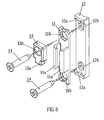
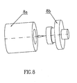
- connection means providing the automatic retraction and return capacity is shown in Fig. 7 as an arrangement of elements bearing the general reference numeral 6 comprising a tubular internally threaded shaft 18a and a bolt 18b.
- Shaft 18a enters through an opening 6a of bar 1 and bolt 18b enters through a corresponding opposite slot 6b of bar 2, whereby a connection is accomplished with spring 5 being encaged in between tubular shaft 18a and bolt 18b and subsequent screwing of bolt 18b into the internally threaded tubular shaft 18a.
- a tensile force is exerted onto spring 5 when bar 2 moves away from bar 1 (Fig. 13), thereby storing energy for an automatic return of bars 1, 2 in an abutting condition as soon as one corrects the position of the latch means and the sliding panel may smoothly close onto the fixed frame profile member.
- the proposed multipoint latching assembly comprises means 9 for the stabilizing thereof at locked condition.
- Such stabilizing means 9 as shown in Fig. 14 comprises an internally threaded tubular pin 22 including a head with two differing diameters 22a, 22b, a pin 22c and a spring 19.
- Pin 22 enters through slot 9b of bar 2 and protrudes through opening 9a of bar 1 thereby being wound with spring means 19 and receiving pin 22c that is being screwed therein.
- slot 9b adapted to receiving the stabilizing assembly has a characteristic form with an elongated portion 9b' and a rounded end portion 9b" with an enlarged diameter.
- the latching assembly of the invention is free to perform a reciprocating movement.
- head 22b thereof having a relatively smaller diameter sits within this rounded end portion 9b" thereby stabilizing the multipoint latching assembly of the invention, since head 22b of pin 22 cannot move out of such position unless an axial pressure is exerted along the stabilizing assembly 9 to result in temporary compression of spring means 19 and storage of energy therein such energy being released whenever said pin 22 again arrives at the rounded end portion 9b" of slot 9b.
Landscapes
- Engineering & Computer Science (AREA)
- Mechanical Engineering (AREA)
- Wing Frames And Configurations (AREA)
- Lock And Its Accessories (AREA)
Applications Claiming Priority (2)
| Application Number | Priority Date | Filing Date | Title |
|---|---|---|---|
| GR2004100204 | 2004-05-20 | ||
| GR20040100204A GR1004956B (el) | 2004-05-20 | 2004-05-20 | Διαταξη κλειδωματος πολλαπλων σημειων για συρομενα |
Publications (2)
| Publication Number | Publication Date |
|---|---|
| EP1598508A1 true EP1598508A1 (de) | 2005-11-23 |
| EP1598508B1 EP1598508B1 (de) | 2011-01-19 |
Family
ID=34897626
Family Applications (1)
| Application Number | Title | Priority Date | Filing Date |
|---|---|---|---|
| EP05386013A Expired - Lifetime EP1598508B1 (de) | 2004-05-20 | 2005-05-20 | Mehrpunktverriegelungsvorrichtung für Schiebetüren |
Country Status (4)
| Country | Link |
|---|---|
| EP (1) | EP1598508B1 (de) |
| AT (1) | ATE496192T1 (de) |
| DE (1) | DE602005025960D1 (de) |
| GR (1) | GR1004956B (de) |
Cited By (3)
| Publication number | Priority date | Publication date | Assignee | Title |
|---|---|---|---|---|
| WO2009016420A1 (en) * | 2007-08-02 | 2009-02-05 | Lock Industry Domus Security S.A. | Multipoint locking assembly for sliding doors and windows |
| EP2876235A1 (de) | 2013-11-21 | 2015-05-27 | Lock Industry Domus Security S.A. | Verriegelungsanordnung für Schiebetüren und -fenster |
| US20200032561A1 (en) * | 2017-03-27 | 2020-01-30 | Rittal Gmbh & Co. Kg | Push rod lock for a switchgear cabinet housing, corresponding arrangement, and corresponding method |
Citations (3)
| Publication number | Priority date | Publication date | Assignee | Title |
|---|---|---|---|---|
| EP0644308A1 (de) | 1993-09-14 | 1995-03-22 | Schlegel (Uk) Holdings Limited | Verschluss für Schiebetür |
| FR2824355A1 (fr) * | 2001-05-07 | 2002-11-08 | Ferco Int Usine Ferrures | Ferrure de verrouillage comportant un organe de verrouillage tel qu'un galet champignon |
| EP1361327A1 (de) | 2002-04-24 | 2003-11-12 | Gretsch-Unitas GmbH Baubeschläge | Beschlag |
-
2004
- 2004-05-20 GR GR20040100204A patent/GR1004956B/el unknown
-
2005
- 2005-05-20 EP EP05386013A patent/EP1598508B1/de not_active Expired - Lifetime
- 2005-05-20 AT AT05386013T patent/ATE496192T1/de not_active IP Right Cessation
- 2005-05-20 DE DE602005025960T patent/DE602005025960D1/de not_active Expired - Lifetime
Patent Citations (3)
| Publication number | Priority date | Publication date | Assignee | Title |
|---|---|---|---|---|
| EP0644308A1 (de) | 1993-09-14 | 1995-03-22 | Schlegel (Uk) Holdings Limited | Verschluss für Schiebetür |
| FR2824355A1 (fr) * | 2001-05-07 | 2002-11-08 | Ferco Int Usine Ferrures | Ferrure de verrouillage comportant un organe de verrouillage tel qu'un galet champignon |
| EP1361327A1 (de) | 2002-04-24 | 2003-11-12 | Gretsch-Unitas GmbH Baubeschläge | Beschlag |
Cited By (4)
| Publication number | Priority date | Publication date | Assignee | Title |
|---|---|---|---|---|
| WO2009016420A1 (en) * | 2007-08-02 | 2009-02-05 | Lock Industry Domus Security S.A. | Multipoint locking assembly for sliding doors and windows |
| EP2876235A1 (de) | 2013-11-21 | 2015-05-27 | Lock Industry Domus Security S.A. | Verriegelungsanordnung für Schiebetüren und -fenster |
| US20200032561A1 (en) * | 2017-03-27 | 2020-01-30 | Rittal Gmbh & Co. Kg | Push rod lock for a switchgear cabinet housing, corresponding arrangement, and corresponding method |
| US11946298B2 (en) * | 2017-03-27 | 2024-04-02 | Rittal Gmbh & Co. Kg | Push rod lock for a switchgear cabinet housing, corresponding arrangement, and corresponding method |
Also Published As
| Publication number | Publication date |
|---|---|
| EP1598508B1 (de) | 2011-01-19 |
| DE602005025960D1 (de) | 2011-03-03 |
| GR1004956B (el) | 2005-07-28 |
| ATE496192T1 (de) | 2011-02-15 |
Similar Documents
| Publication | Publication Date | Title |
|---|---|---|
| US20090139283A1 (en) | Hidden lock locked to an inner side of a doorplate | |
| US4655489A (en) | Fastening device | |
| US8042843B2 (en) | Adjustable driving mechanism for panic door lock | |
| EP3417740B1 (de) | Teleskopartige schiene mit blockierungsmechanismus | |
| JP5318414B2 (ja) | ラッチ | |
| KR101234527B1 (ko) | 롤방충망의 록킹구조 | |
| US3455591A (en) | Automatic latching flush bolt assembly | |
| EP1598508A1 (de) | Mehrpunktverriegelungsvorrichtung für Schiebetüren | |
| CN114458091B (zh) | 门锁结构 | |
| KR20160052996A (ko) | 롤방충망의 프레임에 장착되는 록킹구조 | |
| EP3162993A1 (de) | Verschlussmechanismus für ein fenster oder eine tür | |
| JP4080146B2 (ja) | 扉錠用受金具 | |
| EP1988237A1 (de) | Schliessriegel und Schliessblechgehäuse mit Verriegelungsmittel | |
| CN120225787A (zh) | 自动锁定式固定钩 | |
| JP2656999B2 (ja) | 突放しばねを備えた改良型反動掛合動作式ラッチ | |
| JP4047772B2 (ja) | 開閉装置における締結構造及び締結方法 | |
| US10407943B2 (en) | Temporary door hardware system and door | |
| JP4025241B2 (ja) | 開閉装置のガイドレール構造 | |
| JP3993834B2 (ja) | 開閉装置用ガイドレールの補強構造 | |
| CN219910390U (zh) | 一种导轨式自动上锁的碟锁 | |
| EP2207945A1 (de) | Mehrpunktverriegelungsanordnung für schiebetüren und fenster | |
| GB2463991A (en) | Striker plate for use in a door latch with angled tongue | |
| JP3907621B2 (ja) | 引違戸錠 | |
| WO2002010540A1 (en) | Rolling chock in tilting bar lock | |
| EP3653814B1 (de) | Schloss mit einem rollenriegel |
Legal Events
| Date | Code | Title | Description |
|---|---|---|---|
| PUAI | Public reference made under article 153(3) epc to a published international application that has entered the european phase |
Free format text: ORIGINAL CODE: 0009012 |
|
| AK | Designated contracting states |
Kind code of ref document: A1 Designated state(s): AT BE BG CH CY CZ DE DK EE ES FI FR GB GR HU IE IS IT LI LT LU MC NL PL PT RO SE SI SK TR |
|
| AX | Request for extension of the european patent |
Extension state: AL BA HR LV MK YU |
|
| 17P | Request for examination filed |
Effective date: 20060522 |
|
| AKX | Designation fees paid |
Designated state(s): AT BE BG CH CY CZ DE DK EE ES FI FR GB GR HU IE IS IT LI LT LU MC NL PL PT RO SE SI SK TR |
|
| AXX | Extension fees paid |
Extension state: AL Payment date: 20060522 Extension state: MK Payment date: 20060522 |
|
| 17Q | First examination report despatched |
Effective date: 20100223 |
|
| GRAP | Despatch of communication of intention to grant a patent |
Free format text: ORIGINAL CODE: EPIDOSNIGR1 |
|
| GRAS | Grant fee paid |
Free format text: ORIGINAL CODE: EPIDOSNIGR3 |
|
| GRAA | (expected) grant |
Free format text: ORIGINAL CODE: 0009210 |
|
| AK | Designated contracting states |
Kind code of ref document: B1 Designated state(s): AT BE BG CH CY CZ DE DK EE ES FI FR GB GR HU IE IS IT LI LT LU MC NL PL PT RO SE SI SK TR |
|
| AX | Request for extension of the european patent |
Extension state: AL MK |
|
| REG | Reference to a national code |
Ref country code: GB Ref legal event code: FG4D |
|
| REG | Reference to a national code |
Ref country code: CH Ref legal event code: EP |
|
| REG | Reference to a national code |
Ref country code: IE Ref legal event code: FG4D |
|
| REF | Corresponds to: |
Ref document number: 602005025960 Country of ref document: DE Date of ref document: 20110303 Kind code of ref document: P |
|
| REG | Reference to a national code |
Ref country code: DE Ref legal event code: R096 Ref document number: 602005025960 Country of ref document: DE Effective date: 20110303 |
|
| REG | Reference to a national code |
Ref country code: NL Ref legal event code: VDEP Effective date: 20110119 |
|
| REG | Reference to a national code |
Ref country code: GR Ref legal event code: EP Ref document number: 20110400991 Country of ref document: GR Effective date: 20110513 |
|
| LTIE | Lt: invalidation of european patent or patent extension |
Effective date: 20110119 |
|
| PG25 | Lapsed in a contracting state [announced via postgrant information from national office to epo] |
Ref country code: IS Free format text: LAPSE BECAUSE OF FAILURE TO SUBMIT A TRANSLATION OF THE DESCRIPTION OR TO PAY THE FEE WITHIN THE PRESCRIBED TIME-LIMIT Effective date: 20110519 Ref country code: SE Free format text: LAPSE BECAUSE OF FAILURE TO SUBMIT A TRANSLATION OF THE DESCRIPTION OR TO PAY THE FEE WITHIN THE PRESCRIBED TIME-LIMIT Effective date: 20110119 Ref country code: LT Free format text: LAPSE BECAUSE OF FAILURE TO SUBMIT A TRANSLATION OF THE DESCRIPTION OR TO PAY THE FEE WITHIN THE PRESCRIBED TIME-LIMIT Effective date: 20110119 Ref country code: ES Free format text: LAPSE BECAUSE OF FAILURE TO SUBMIT A TRANSLATION OF THE DESCRIPTION OR TO PAY THE FEE WITHIN THE PRESCRIBED TIME-LIMIT Effective date: 20110430 Ref country code: PT Free format text: LAPSE BECAUSE OF FAILURE TO SUBMIT A TRANSLATION OF THE DESCRIPTION OR TO PAY THE FEE WITHIN THE PRESCRIBED TIME-LIMIT Effective date: 20110519 |
|
| PGFP | Annual fee paid to national office [announced via postgrant information from national office to epo] |
Ref country code: TR Payment date: 20110419 Year of fee payment: 7 |
|
| PG25 | Lapsed in a contracting state [announced via postgrant information from national office to epo] |
Ref country code: BG Free format text: LAPSE BECAUSE OF FAILURE TO SUBMIT A TRANSLATION OF THE DESCRIPTION OR TO PAY THE FEE WITHIN THE PRESCRIBED TIME-LIMIT Effective date: 20110419 Ref country code: PL Free format text: LAPSE BECAUSE OF FAILURE TO SUBMIT A TRANSLATION OF THE DESCRIPTION OR TO PAY THE FEE WITHIN THE PRESCRIBED TIME-LIMIT Effective date: 20110119 Ref country code: CY Free format text: LAPSE BECAUSE OF FAILURE TO SUBMIT A TRANSLATION OF THE DESCRIPTION OR TO PAY THE FEE WITHIN THE PRESCRIBED TIME-LIMIT Effective date: 20110119 Ref country code: BE Free format text: LAPSE BECAUSE OF FAILURE TO SUBMIT A TRANSLATION OF THE DESCRIPTION OR TO PAY THE FEE WITHIN THE PRESCRIBED TIME-LIMIT Effective date: 20110119 Ref country code: SI Free format text: LAPSE BECAUSE OF FAILURE TO SUBMIT A TRANSLATION OF THE DESCRIPTION OR TO PAY THE FEE WITHIN THE PRESCRIBED TIME-LIMIT Effective date: 20110119 Ref country code: NL Free format text: LAPSE BECAUSE OF FAILURE TO SUBMIT A TRANSLATION OF THE DESCRIPTION OR TO PAY THE FEE WITHIN THE PRESCRIBED TIME-LIMIT Effective date: 20110119 Ref country code: FI Free format text: LAPSE BECAUSE OF FAILURE TO SUBMIT A TRANSLATION OF THE DESCRIPTION OR TO PAY THE FEE WITHIN THE PRESCRIBED TIME-LIMIT Effective date: 20110119 Ref country code: AT Free format text: LAPSE BECAUSE OF FAILURE TO SUBMIT A TRANSLATION OF THE DESCRIPTION OR TO PAY THE FEE WITHIN THE PRESCRIBED TIME-LIMIT Effective date: 20110119 |
|
| PG25 | Lapsed in a contracting state [announced via postgrant information from national office to epo] |
Ref country code: EE Free format text: LAPSE BECAUSE OF FAILURE TO SUBMIT A TRANSLATION OF THE DESCRIPTION OR TO PAY THE FEE WITHIN THE PRESCRIBED TIME-LIMIT Effective date: 20110119 Ref country code: DK Free format text: LAPSE BECAUSE OF FAILURE TO SUBMIT A TRANSLATION OF THE DESCRIPTION OR TO PAY THE FEE WITHIN THE PRESCRIBED TIME-LIMIT Effective date: 20110119 |
|
| PLBE | No opposition filed within time limit |
Free format text: ORIGINAL CODE: 0009261 |
|
| STAA | Information on the status of an ep patent application or granted ep patent |
Free format text: STATUS: NO OPPOSITION FILED WITHIN TIME LIMIT |
|
| PG25 | Lapsed in a contracting state [announced via postgrant information from national office to epo] |
Ref country code: RO Free format text: LAPSE BECAUSE OF FAILURE TO SUBMIT A TRANSLATION OF THE DESCRIPTION OR TO PAY THE FEE WITHIN THE PRESCRIBED TIME-LIMIT Effective date: 20110119 Ref country code: SK Free format text: LAPSE BECAUSE OF FAILURE TO SUBMIT A TRANSLATION OF THE DESCRIPTION OR TO PAY THE FEE WITHIN THE PRESCRIBED TIME-LIMIT Effective date: 20110119 Ref country code: CZ Free format text: LAPSE BECAUSE OF FAILURE TO SUBMIT A TRANSLATION OF THE DESCRIPTION OR TO PAY THE FEE WITHIN THE PRESCRIBED TIME-LIMIT Effective date: 20110119 |
|
| 26N | No opposition filed |
Effective date: 20111020 |
|
| PG25 | Lapsed in a contracting state [announced via postgrant information from national office to epo] |
Ref country code: MC Free format text: LAPSE BECAUSE OF NON-PAYMENT OF DUE FEES Effective date: 20110531 |
|
| REG | Reference to a national code |
Ref country code: CH Ref legal event code: PL |
|
| GBPC | Gb: european patent ceased through non-payment of renewal fee |
Effective date: 20110520 |
|
| PG25 | Lapsed in a contracting state [announced via postgrant information from national office to epo] |
Ref country code: LI Free format text: LAPSE BECAUSE OF NON-PAYMENT OF DUE FEES Effective date: 20110531 Ref country code: CH Free format text: LAPSE BECAUSE OF NON-PAYMENT OF DUE FEES Effective date: 20110531 |
|
| REG | Reference to a national code |
Ref country code: DE Ref legal event code: R097 Ref document number: 602005025960 Country of ref document: DE Effective date: 20111020 |
|
| REG | Reference to a national code |
Ref country code: FR Ref legal event code: ST Effective date: 20120131 |
|
| REG | Reference to a national code |
Ref country code: IE Ref legal event code: MM4A |
|
| PG25 | Lapsed in a contracting state [announced via postgrant information from national office to epo] |
Ref country code: FR Free format text: LAPSE BECAUSE OF NON-PAYMENT OF DUE FEES Effective date: 20110531 Ref country code: IE Free format text: LAPSE BECAUSE OF NON-PAYMENT OF DUE FEES Effective date: 20110520 |
|
| PG25 | Lapsed in a contracting state [announced via postgrant information from national office to epo] |
Ref country code: GB Free format text: LAPSE BECAUSE OF NON-PAYMENT OF DUE FEES Effective date: 20110520 |
|
| REG | Reference to a national code |
Ref country code: AT Ref legal event code: MK05 Ref document number: 496192 Country of ref document: AT Kind code of ref document: T Effective date: 20110119 |
|
| PG25 | Lapsed in a contracting state [announced via postgrant information from national office to epo] |
Ref country code: LU Free format text: LAPSE BECAUSE OF NON-PAYMENT OF DUE FEES Effective date: 20110520 |
|
| PGFP | Annual fee paid to national office [announced via postgrant information from national office to epo] |
Ref country code: DE Payment date: 20130604 Year of fee payment: 9 |
|
| PG25 | Lapsed in a contracting state [announced via postgrant information from national office to epo] |
Ref country code: HU Free format text: LAPSE BECAUSE OF FAILURE TO SUBMIT A TRANSLATION OF THE DESCRIPTION OR TO PAY THE FEE WITHIN THE PRESCRIBED TIME-LIMIT Effective date: 20110119 |
|
| PG25 | Lapsed in a contracting state [announced via postgrant information from national office to epo] |
Ref country code: TR Free format text: LAPSE BECAUSE OF NON-PAYMENT OF DUE FEES Effective date: 20120520 |
|
| PGFP | Annual fee paid to national office [announced via postgrant information from national office to epo] |
Ref country code: IT Payment date: 20140520 Year of fee payment: 10 |
|
| REG | Reference to a national code |
Ref country code: DE Ref legal event code: R119 Ref document number: 602005025960 Country of ref document: DE |
|
| REG | Reference to a national code |
Ref country code: DE Ref legal event code: R119 Ref document number: 602005025960 Country of ref document: DE Effective date: 20141202 |
|
| PG25 | Lapsed in a contracting state [announced via postgrant information from national office to epo] |
Ref country code: DE Free format text: LAPSE BECAUSE OF NON-PAYMENT OF DUE FEES Effective date: 20141202 |
|
| PG25 | Lapsed in a contracting state [announced via postgrant information from national office to epo] |
Ref country code: IT Free format text: LAPSE BECAUSE OF NON-PAYMENT OF DUE FEES Effective date: 20150520 |
|
| PGFP | Annual fee paid to national office [announced via postgrant information from national office to epo] |
Ref country code: GR Payment date: 20151103 Year of fee payment: 11 |
|
| REG | Reference to a national code |
Ref country code: GR Ref legal event code: ML Ref document number: 20110400991 Country of ref document: GR Effective date: 20161207 |
|
| PG25 | Lapsed in a contracting state [announced via postgrant information from national office to epo] |
Ref country code: GR Free format text: LAPSE BECAUSE OF NON-PAYMENT OF DUE FEES Effective date: 20161207 |