EP1598320A1 - Biologischer Filter zur Abwasserbehandlung - Google Patents
Biologischer Filter zur Abwasserbehandlung Download PDFInfo
- Publication number
- EP1598320A1 EP1598320A1 EP20040291298 EP04291298A EP1598320A1 EP 1598320 A1 EP1598320 A1 EP 1598320A1 EP 20040291298 EP20040291298 EP 20040291298 EP 04291298 A EP04291298 A EP 04291298A EP 1598320 A1 EP1598320 A1 EP 1598320A1
- Authority
- EP
- European Patent Office
- Prior art keywords
- effluents
- filtered
- inlet
- reactor
- outlet
- Prior art date
- Legal status (The legal status is an assumption and is not a legal conclusion. Google has not performed a legal analysis and makes no representation as to the accuracy of the status listed.)
- Granted
Links
- 238000001914 filtration Methods 0.000 claims abstract description 156
- 239000002028 Biomass Substances 0.000 claims abstract description 54
- 229910052500 inorganic mineral Inorganic materials 0.000 claims abstract description 4
- 239000011707 mineral Substances 0.000 claims abstract description 4
- 239000004033 plastic Substances 0.000 claims abstract description 3
- 239000007789 gas Substances 0.000 claims description 64
- 239000010802 sludge Substances 0.000 claims description 48
- 238000011282 treatment Methods 0.000 claims description 21
- 238000009434 installation Methods 0.000 claims description 19
- 238000000034 method Methods 0.000 claims description 18
- 238000011144 upstream manufacturing Methods 0.000 claims description 18
- 238000005406 washing Methods 0.000 claims description 17
- 230000008569 process Effects 0.000 claims description 16
- MYMOFIZGZYHOMD-UHFFFAOYSA-N Dioxygen Chemical compound O=O MYMOFIZGZYHOMD-UHFFFAOYSA-N 0.000 claims description 10
- 238000011084 recovery Methods 0.000 claims description 10
- 239000000463 material Substances 0.000 claims description 9
- 238000001514 detection method Methods 0.000 claims description 8
- 229910001882 dioxygen Inorganic materials 0.000 claims description 8
- 238000010908 decantation Methods 0.000 claims description 7
- 230000009466 transformation Effects 0.000 claims description 7
- 239000007787 solid Substances 0.000 claims description 6
- 238000004891 communication Methods 0.000 claims description 5
- 239000012535 impurity Substances 0.000 claims description 5
- 230000014759 maintenance of location Effects 0.000 claims description 5
- 238000007599 discharging Methods 0.000 claims description 4
- 239000002562 thickening agent Substances 0.000 claims description 4
- XLYOFNOQVPJJNP-UHFFFAOYSA-N water Substances O XLYOFNOQVPJJNP-UHFFFAOYSA-N 0.000 claims description 4
- 230000005484 gravity Effects 0.000 claims description 3
- 239000002245 particle Substances 0.000 claims description 3
- 230000001960 triggered effect Effects 0.000 claims description 3
- 239000011343 solid material Substances 0.000 claims description 2
- 230000000712 assembly Effects 0.000 claims 1
- 238000000429 assembly Methods 0.000 claims 1
- 239000002699 waste material Substances 0.000 claims 1
- 235000021183 entrée Nutrition 0.000 description 18
- 244000005700 microbiome Species 0.000 description 11
- 238000000746 purification Methods 0.000 description 6
- 239000000725 suspension Substances 0.000 description 6
- 230000009471 action Effects 0.000 description 4
- 239000003344 environmental pollutant Substances 0.000 description 4
- 231100000719 pollutant Toxicity 0.000 description 4
- OKTJSMMVPCPJKN-UHFFFAOYSA-N Carbon Chemical compound [C] OKTJSMMVPCPJKN-UHFFFAOYSA-N 0.000 description 3
- 238000009825 accumulation Methods 0.000 description 3
- 230000008901 benefit Effects 0.000 description 3
- 230000000717 retained effect Effects 0.000 description 3
- 239000011324 bead Substances 0.000 description 2
- 229910052799 carbon Inorganic materials 0.000 description 2
- 230000015556 catabolic process Effects 0.000 description 2
- 239000004927 clay Substances 0.000 description 2
- 238000006731 degradation reaction Methods 0.000 description 2
- 230000029087 digestion Effects 0.000 description 2
- 238000007689 inspection Methods 0.000 description 2
- 239000000203 mixture Substances 0.000 description 2
- 230000003647 oxidation Effects 0.000 description 2
- 238000007254 oxidation reaction Methods 0.000 description 2
- 229910052760 oxygen Inorganic materials 0.000 description 2
- 239000002351 wastewater Substances 0.000 description 2
- QYLJIYOGHRGUIH-CIUDSAMLSA-N Arg-Ile Chemical compound CC[C@H](C)[C@@H](C(O)=O)NC(=O)[C@@H](N)CCCNC(N)=N QYLJIYOGHRGUIH-CIUDSAMLSA-N 0.000 description 1
- IJGRMHOSHXDMSA-UHFFFAOYSA-N Atomic nitrogen Chemical compound N#N IJGRMHOSHXDMSA-UHFFFAOYSA-N 0.000 description 1
- 241000206607 Porphyra umbilicalis Species 0.000 description 1
- 241001080024 Telles Species 0.000 description 1
- 238000005054 agglomeration Methods 0.000 description 1
- 230000002776 aggregation Effects 0.000 description 1
- 230000001174 ascending effect Effects 0.000 description 1
- QVGXLLKOCUKJST-UHFFFAOYSA-N atomic oxygen Chemical compound [O] QVGXLLKOCUKJST-UHFFFAOYSA-N 0.000 description 1
- 230000015572 biosynthetic process Effects 0.000 description 1
- 230000000740 bleeding effect Effects 0.000 description 1
- 230000008859 change Effects 0.000 description 1
- 238000006243 chemical reaction Methods 0.000 description 1
- 238000010586 diagram Methods 0.000 description 1
- 238000010790 dilution Methods 0.000 description 1
- 239000012895 dilution Substances 0.000 description 1
- 239000004794 expanded polystyrene Substances 0.000 description 1
- 238000000605 extraction Methods 0.000 description 1
- 230000004907 flux Effects 0.000 description 1
- 239000011521 glass Substances 0.000 description 1
- 238000002347 injection Methods 0.000 description 1
- 239000007924 injection Substances 0.000 description 1
- 238000002156 mixing Methods 0.000 description 1
- 229910052757 nitrogen Inorganic materials 0.000 description 1
- 238000011369 optimal treatment Methods 0.000 description 1
- 239000005416 organic matter Substances 0.000 description 1
- 125000001477 organic nitrogen group Chemical group 0.000 description 1
- 239000001301 oxygen Substances 0.000 description 1
- 230000035699 permeability Effects 0.000 description 1
- 239000011148 porous material Substances 0.000 description 1
- 239000002364 soil amendment Substances 0.000 description 1
- 238000010099 solid forming Methods 0.000 description 1
- 238000004065 wastewater treatment Methods 0.000 description 1
Images


Classifications
-
- C—CHEMISTRY; METALLURGY
- C02—TREATMENT OF WATER, WASTE WATER, SEWAGE, OR SLUDGE
- C02F—TREATMENT OF WATER, WASTE WATER, SEWAGE, OR SLUDGE
- C02F3/00—Biological treatment of water, waste water, or sewage
- C02F3/02—Aerobic processes
- C02F3/10—Packings; Fillings; Grids
- C02F3/101—Arranged-type packing, e.g. stacks, arrays
-
- C—CHEMISTRY; METALLURGY
- C02—TREATMENT OF WATER, WASTE WATER, SEWAGE, OR SLUDGE
- C02F—TREATMENT OF WATER, WASTE WATER, SEWAGE, OR SLUDGE
- C02F3/00—Biological treatment of water, waste water, or sewage
- C02F3/02—Aerobic processes
- C02F3/06—Aerobic processes using submerged filters
-
- Y—GENERAL TAGGING OF NEW TECHNOLOGICAL DEVELOPMENTS; GENERAL TAGGING OF CROSS-SECTIONAL TECHNOLOGIES SPANNING OVER SEVERAL SECTIONS OF THE IPC; TECHNICAL SUBJECTS COVERED BY FORMER USPC CROSS-REFERENCE ART COLLECTIONS [XRACs] AND DIGESTS
- Y02—TECHNOLOGIES OR APPLICATIONS FOR MITIGATION OR ADAPTATION AGAINST CLIMATE CHANGE
- Y02W—CLIMATE CHANGE MITIGATION TECHNOLOGIES RELATED TO WASTEWATER TREATMENT OR WASTE MANAGEMENT
- Y02W10/00—Technologies for wastewater treatment
- Y02W10/10—Biological treatment of water, waste water, or sewage
Definitions
- the invention relates to a biological filter for the treatment of spent effluents, a filtration process using such a filter, a filtration plant comprising a plurality of such filters, as well as a treatment plant comprising at least one such filter or filtration facility.
- the invention relates more particularly to a biological filter, or "biofilter”, wherein a biomass containing suitable microorganisms is fixed on a submerged support.
- the effluents to be filtered may contain materials suspension, organic and / or mineral, which are retained in the filter, as well as dissolved or particulate organic impurities, which are transformed by the action of biomass.
- Document FR-A-2,632,947 describes a filter whose biomass is fixed on a floating support, the low density of the support being intended for facilitate washing.
- the washing is done by injection water purified against the current, and high flow, so as to loosen the materials forming a support.
- the invention proposes an upflow biological filter and co-current, arranged to overcome these various disadvantages.
- the reactor is subdivided into minus three superimposed compartments forming floors by means of at least two walls provided with openings, said openings being arranged to retain the filtering means, so as to form in the reactor at least two filtration stages and an upper outlet stage, the output of filtered effluents opening into the upper outlet stage, each filtration stage being provided with a layer of its own filtering means, and comprising, in part lower, a withdrawal output of excess biomass, the quantity and density of the filtering means in each stage of being such that, in racking, the lower part of at least the lower stage or floors in which opens the withdrawal outlet is free of filtering means, to allow recovery of excess biomass.
- the filter according to the invention thus has several filtration stages which can be discarded independently of each other from their biomass excessively, which makes it possible to carry out the washing in a selective manner, by determining, as and when the filtration process, which fraction of the support needs to be washed.
- the presence of several filtration stages also has the advantage of allow a modular filtration, optimally adapting the support of biomass in each filtration stage, resulting in efficiency increased filtration process.
- At least two filtration stages comprise different filtering means, by the nature of their support and / or the fixed biomass, and differ for example in their density.
- the subject of the invention is a filtration installation, comprising a plurality of filters as previously described, disposed of so to operate in parallel.
- the installation includes an effluent inlet to be filtered connected to the inlet effluents to be filtered from each of the filters, an oxygenated gas inlet, connected to the oxygenated gas inlet of each of the filters, an output of filtered effluents connected to the outlet of each of the filters, and at least one withdrawal outlet connected to the withdrawal outlets of each of the filters.
- the installation also includes means for selectively supply of effluents to be filtered and of oxygenated gas from each of the filters, control means for filtering, stopping and recovering the excess biomass so that the filtration of effluent to be filtered by a minimum number of filters, and stopping the other filters in view of the recovery of excess biomass and / or de and denitrification at least a portion of the effluents filtered in said other filters.
- the invention relates to a purification plant spent effluent comprising at least one such filter or such a plant of filtration.
- Filter 1 is intended for the biological treatment of spent effluents. It is intended in particular for the treatment of effluents having undergone prior decantation stage to eliminate a significant part of their materials in suspension.
- such a filter 1 can be included in an installation which in has several and, more generally, in a wastewater treatment plant further comprising at least one decanter and an anaerobic digester of sludge.
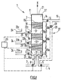
- the filter 1 comprises a closed reactor 2, here of substantially cylindrical shape, defining a longitudinal main axis X.
- the reactor 2 can also be of substantially parallelepipedal shape.
- the reactor 2 is arranged so that its main axis X is oriented substantially vertically.
- the flow of effluents to be filtered is intended to circulate in the longitudinal direction, from bottom to top, to be biologically filtered.
- the reactor 2 comprises, at the bottom, an inlet 3 of the effluents to be filtered, connected to a supply duct 4 provided with a valve 5, and a gas inlet 6 oxygenated, connected to a supply duct 7 provided with a valve 8.
- the supply of oxygenated gas, such as air, is intended to penetrate in the reactor 2 the oxygen necessary for the development of microorganisms aerobes used for filtration.
- the two Inlets 3, 6 are provided in the bottom wall 9 of the reactor 2 and allow to penetrate the effluents to be filtered and the oxygenated gas into a compartment 10.
- the inlet compartment 10 is delimited by the bottom wall 9, part of the side wall 11 of the reactor, and by an upper wall 12 extending transversely over the entire width of the reactor 2.
- the internal wall 12 is permeable to the effluents to be filtered and to the oxygenated gas, so as to allow the upward passage of effluents and gas through it.
- the openings 13a, 13c are formed in the bottom wall 9 so that ensure a good distribution of effluent and gas flows. It can be expected in addition one or more diffusers of fine bubbles of gas, for example air, allowing a homogeneous distribution of the gas within the flow of effluents to be filtered.
- the output 14 of the filtered effluents is located in the upper part of the reactor 2. According to the embodiments shown, this output 14, connected to a exhaust duct 15 filtered effluent provided with a valve 16, is provided in the side wall 11, and opens into an upper outlet stage 17 of the reactor 2. The evacuation of the filtered effluents is carried out by overflow.
- the filter 1 is of the upflow type, the gas supply oxygenated being carried out in co-current.
- the filter 1 comprises, inside the reactor 2, and interposed between the inlet 3 effluents to be filtered and the outlet 14 of filtered effluents, filtering means 18.
- the filtering means 18 comprise layers of particles of a material microporous solid forming supports, and a purifying biomass hooked onto the surface of said supports. To do this, the supports were previously seeded with aerobic microorganisms that grew on said supports and clung to it. During the implementation of the filtration, the fact that the biomass is hooked to a support makes it possible to optimize the contact between the pollutants to be treated and the micro-organisms, which leads to faster degradation of organic matter.
- the filtering means 18 have a density lower than that of the effluents to be filtered.
- the density of the effluents to be filtered depends on the quantity of pollutants present, this quantity being variable according to the origin of the effluents and the or the previous treatment (s) they have undergone.
- the reactor 2 is subdivided into four compartments superimposed on each other, according to the the longitudinal direction of the reactor, which gives the reactor a structure floors.
- the compartments are separated from one another by means of three walls 19a, 19b, 19c provided with openings, said walls extending transversely in the reactor 2 over the entire cross section thereof.
- the openings walls 19a, 19b, 19c are arranged to retain the filtering means 18, and pass the effluent streams to be filtered and gas.
- openings are distributed over the surface of the walls 19a, 19b, 19c in such a way that they ensure a good distribution of effluents and gases in the compartments of the reactor 2.
- the walls 19 provided with openings are grids mesh adapted.
- compartments thus form, in the reactor 2, on the one hand three stages of filtration respectively lower 20a, intermediate 20b, and upper 20c, and on the other hand the upper outlet stage 17.
- the upper outlet stage 17 is formed between the upper wall 21 of the reactor 2 and the upper wall 19c disposed opposite, and is free of filter media.
- the stage of lower filtration 20a is located directly above the entrance compartment 10, and it is separated by the inner wall 12.
- the stage of lower filtration 20a is delimited downwards by the lower wall 9 of the reactor 2, the inlet openings 13a of the effluents to be filtered and 13c of the inlet of gas opening directly into said lower filtration stage 20a.
- Each filtration stage 20a, 20b, 20c is provided with its own means During the upward circulation of the effluents in the reactor 2, the filtering means 18 are retained in the upper part of the filtration stage considered by the wall 19a, 19b, 19c corresponding.
- the geometry and the size of the openings of said walls are adapted to the size and the geometry of the filtering means 18.
- Each filtration stage 20a, 20b, 20c further comprises in the lower part a withdrawal outlet 22a, 22b, 22c of the excess biomass, arranged in the side wall 11 of the reactor 2.
- These outlets 22a, 22b, 22c have as their function to allow the regular evacuation of excess biomass form in each stage 20a, 20b, 20c during the filtration, this biomass not only from the continuous growth of microorganisms on the supports, but also the accumulation in each floor of suspended matter.
- each withdrawal outlet 22a, 22b, 22c is connected a conduit of withdrawal 24 provided with a valve 25.
- a recovery compartment 23a, 23b, 23c of said excess biomass can be provided, said compartment being in communication with the corresponding withdrawal conduit 24.
- the quantity and density of the filtering means 18 are such that, in withdrawal mode of the biomass surplus, the lower part of each floor into which a withdrawal outlet 22a, 22b, 22c is free of filtering means 18.
- the quantity and the density of the filtering means 18 in each filtration stage 20a, 20b, 20c are provided for said filtering means 18 float during the withdrawal of excess biomass, while being selected in their filtration stage 20a, 20b, 20c by the wall 19a, 19b, 19c corresponding.
- a free space 31 free of means filter there is, in the lower part of filtration stages 20a, 20b, 20c, a free space 31 free of means filter.
- This arrangement allows, at each filtration stage 20a, 20b, 20c, the recovery of surplus biomass avoiding simultaneous training filtering means 18 during racking which could reduce the filtration capacity of the reactor 2.
- the filtering means 18 of the upper stage 20c may not be located only in the upper part, but distributed in substantially the the entire volume of said upper stage 20c during racking.
- retaining means such as walls 19d, 19e, 19f, provided with openings, for example grids, arranged in the withdrawal ducts 24, in the vicinity of one or all the outlets bleeding 22a, 22b, 22c.
- the openings of the walls 19d, 19e, 19f or the mesh grids are such that they hold the filtering means 18 in each filtration stage 20a, 20b, 20c, and pass the excess biomass.
- At least one filtration stage 20a, 20b, 20c is provided with a means 26 for detecting the amount of excess biomass.
- the detection is done for example by the emission of a wave beam (infrared or other) and receiving it through the medium considered.
- detection 26 may be in accordance with that described in the patent application FR-A-2 731 272.
- the detection means 26 is intended, when the filter 1 is in functioning, to detect the accumulation of biomass and the predefined threshold above which the momentary shutdown of filter 1 is triggered.
- the shutdown of the filter is carried out by closing the valves 5 and 8, and the opening of the withdrawal outlet 22a, 22b or 22c of the stage concerned, by opening the corresponding valve.
- At least two filtration stages 20a, 20b, 20c comprise different filtering means 18, by the nature of their support and / or fixed biomass.
- the filtering means 18 of at least two stages 20a, 20b, 20c differ in their density, so as to adapt so optimal density of the filtering means to the amount of pollutants present in each floor, this quantity of pollutants affecting the density of the effluents to be filtered, and thus ensure that said means filtering float during racking.
- filtering means 18 whose density corresponds respectively to one and the other of the two variants exposed above.
- supports comprising density balls between 0.5 and 1, and in particular of the order of 0.7.
- each filtration stage 20a, 20b, 20c are treated effluents having different properties. Indeed, the effluents, which pass through the stages of successive filtration processes, are less and less polluted as and when they are upward circulation. And, because of the stage structure of reactor 2, it is thus possible to optimize the treatment of the effluents in each of the stages of filtration 20a, 20b, 20c, selecting the filtering means 18 the best adapted to the degree of pollution of the effluents considered, in terms of the nature of the support, biomass or density of the filtering means 18.
- the supports used for the filtering means 18 may be formed of balls, whose diameter is between 1 and 30 mm, and in particular between 4 and 10 mm. It is possible to use balls of different diameters in the different stages of filtration. These beads may be formed of plastic or mineral materials foamed, such as expanded glass, expanded clay, or expanded polystyrene. These supports have the advantage, by their geometry and the material of which they are made, to offer a surface of exchange important with the effluents to be filtered.
- the filter 1 may comprise recirculation means 27 of the filtered effluents, comprising a conduit 28 associated with a pump 29, said means being provided between the outlet 14 and the inlet 3 of the effluents. Ways 27 are arranged to recover at least a portion of the filtered effluents in reactor 2, and return this portion to the inlet 3 of reactor 2 for additional treatment.
- the means recirculation devices 27 are arranged to conduct at least a part of the filtered, and therefore nitrified, effluents to a particular stage of denitrification 30, located in the lower part of the reactor 2.
- the stage of denitrification 30 to be an anoxic zone, it is then expected that the entry 6 of oxygenated gas is no longer at the same level as entry 3 of the effluent to be filtered, but above said denitrification stage 30, and by therefore above the inlet 3 of the effluents to be filtered.
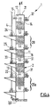
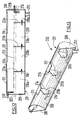
- FIG. 4 illustrates a filter 1 according to a fourth embodiment of the invention.
- the filter 1 comprises five filtration stages 20.
- the inlet 3 of effluents to be filtered and the inlet 6 of oxygenated gas are provided on the side wall 11 of the reactor 2, and open under the lower filtration stage 20a.
- the supply duct 4 effluents to be filtered extend substantially horizontally from the inlet 3, then forms a bend and extends substantially vertically along the wall This arrangement makes it possible, in particular in the event of failure of the filter 1, or if it is necessary to change the feed pump, to prevent the effluents present in the reactor 2 do not flow by gravity, desired, through the conduit 4.
- conduit 32 opening in the free space 31 from the side wall 11 of the reactor, for example substantially the opposite of the withdrawal outlet of excess biomass.
- the conduit 32 is connected to a control tool, intended for example to control the pH value of the effluents present in the filtration stage considered.
- a window 33 may be provided on the side wall 11 of the reactor 2, each filtration stage 20. This window 33 allows in particular the emission and the reception of the wave beam of the detection means 26.
- the filter 1 of FIG. 4 can be adapted to one of the configurations of FIG. to 3 (may or may not be provided: an input compartment 10, a plurality openings 13a, 13c connected to conduits 13b, 13d, a stage of denitrification 30, recirculation means 27, etc.).
- valves 5, 8 which leads to the sending in the reactor 2 on the one hand, an effluent stream to be filtered, via the inlet 3, and on the other hand of a flow of oxygenated gas, through the inlet 6.
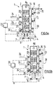
- the effluents and the gas circulate therefore upwardly, in the direction of the arrows F1 of Figure 5a.
- the effluents introduced into the reactor 2 are filtered successively by upflow in the successive filtration stages 20a, 20b, 20c.
- At least some of these filtered effluents may be fed to the reactor 2, via the recirculation duct 28 (arrow F2). These effluents are thus subjected to additional filtration which improves the degree of treatment.
- the effluents in recirculation pass through the denitrification stage 30, where they undergo a denitrification stage, in anoxic zone.
- it may be provided to periodically close the inlet 3 of the effluents to filter and the inlet 6 of oxygenated gas, by action on the valves 5 and 8, and this until formation of an anoxic zone allowing the development of micro-organisms denitrifiers, thanks to which the effluents present in the reactor 2 can undergo the denitrification process.
- the process involves mixing external gases with air sent into the reactor 2, so as to allow the oxidation of said gases.
- Smelly gases are produced by other reactors included in the station in which the filter 1 is located, the oxidation of these gases by passage through the reactor 2 allows the deodorize.
- the inlet 3 of the effluents to be filtered is closed and the inlet 6 of oxygenated gas, by acting on the valves 5 and 8, and opening the withdrawal outlet 22a, 22b, 22c of the filtration stage 20a, 20b, 20c to be washed, by opening the corresponding valve.
- the filtration stage 20a, 20b, 20c to be washed is selected according to the quantity of biomass found there, as detected by the means of detection 26.
- each filtration stage 20a, 20b, 20c is all the more important that the stage is distant from the top of reactor 2.
- the lower stages, in which the filtering means 18 have tend to clog more easily, are washed by a quantity of effluents descendants larger than the upper floors.
- the washing phase can be triggered when the detection means 26 detects a quantity of biomass greater than the threshold predefined, in at least one filtration stage.
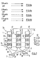
- FIG. 7 illustrating a filtration facility 34 comprising a plurality of filters 1 arranged to operate in a parallel.
- the installation 34 comprises three filters 1 identical to the type shown in Figure 1. However, the installation 34 could have more or fewer filters. Filters could be different from each other, and correspond to any of the embodiments shown in Figures 1 to 4.
- Cutoff means 39 of the effluent feed to be filtered are provided between the conduit 4 and the conduits 36, so as to allow the closure of the effluent feed of all or part of the filters 1.
- cutting means 40 of the oxygenated gas supply are provided between the conduit 7 and the ducts 38, so as to allow the closure of the supply gas from all or part of the filters 1.
- the outlets 14 of the filtered effluents from each filter 2 are each connected to a 41, the three ducts 41 being connected to the exhaust duct 15 filtered effluents.
- the withdrawal outlets 22a, 22b, 22c of each filter 1 are connected to conduits 42, the various conduits 42 being connected to a withdrawal pipe 24.
- the installation also comprises control means respectively filtration 43, stopping the filter 44, and the recovery of biomass surplus 45.
- FIG. 8 a purification station 46 of FIGS. spent effluents.
- the raw effluents are fed via a feed conduit 107 as input of a primary clarifier 100, so as to be rid of a significant part of their suspended matter.
- the primary clarifier 100 comprises an evacuation pipe 109 of the effluents decanted connected to the inlet 3 of the effluents to be filtered from the filter 1, respectively at the inlet 35 of the effluents to be filtered from the filtration installation 34, via the conduit 4, and means for discharging sludge from the decanting.
- Sludge from primary settling is removed to a digester anaerobic sludge 200, so as to allow sludge degradation, by evacuation means, such as an exhaust duct 111, connected to the supply duct 207 in fresh sludge from the digester 200.
- the digester 200 comprises an effluent evacuation outlet, connected, via a discharge duct 209, at the effluent feed inlet at decant from the primary clarifier 100.
- the digester 200 further comprises a sludge discharge outlet connected digestion via an evacuation conduit 212 at the entrance of a thickener 48.
- the thickener 48 has an outlet 49 of the residual water connected to the effluent feed inlet to be decanted from the primary clarifier 100, possibly via the exhaust duct 209 of the effluents of the digester 200.
- the thickener 48 also has an outlet 50 of the thickened sludge.
- These sludge may be suitably packaged and treated with a view to their use, especially for soil amendment. They can also be directed to a landfill or incineration unit.
- the effluents filtered by the filter 1, or the filtration installation 34, are evacuated 15. In the case where the filter 1 is able to retain the suspended matter contained in the effluents to be filtered, the filtered effluents are rejected directly. In the opposite case, the filtered effluents are directed to the inlet of a secondary clarifier 51.
- the filter 1 also includes withdrawal outlets for evacuation biomass by withdrawal lines 24, these being able to be connected either to the inlet of the secondary clarifier 51, or when the station does not include a secondary decanter, at the inlet of the effluent feed at decant from the primary decanter 100 or at the sludge feed inlet fresh from the digester 200.
- the secondary clarifier 51 comprises means for evacuating the sludge from the decantation, connected either to the effluent feed inlet to decanting from the primary clarifier 100 via an evacuation pipe 52, possibly opening in the conduit 209, either at the feed inlet in fresh sludge from the digester 200. Some of these sludges can also be be returned to the top of filter 1 to maintain biomass at a level longed for.
- the secondary clarifier 51 comprises an exhaust duct 53 of decanted effluents.
- a first set of at least one settling panel is inclined according to a first angle ( ⁇ ) of between 15 ° and 60 °
- at least one second set of at least one settling panel is inclined according to a second angle ( ⁇ ) between 15 ° and 60 °
- the angles ( ⁇ , ⁇ ) being chosen so that, when the flow of effluents in the tank, the sludge is deposited on the surface decantation then slide towards the bottom of the tank, at least one passage 117 sludge being provided between the panels of the two together, to allow sludge collected on the upper faces panels to fall by gravity on the bottom 103 of the tank 101.
- the tank has two sets of panels arranged symmetrically by relative to the plane 113, vertical, longitudinal and median of the tank.
- the first set (left) comprises five panels 114a to 114e substantially parallel, superimposed vertically, and spaced apart from each other others of a substantially constant distance L1 of the order of 30 cm.
- the panels 114a to 114e are inclined up and down from the side wall substantially vertical from the tank to the vertical plane 113, with an angle ⁇ of the order of 45 °.
- the panels 114 have different widths I according to their distance by compared to the bottom 103 of the tank, but lengths L (parallel to flow of effluents) substantially equal.
- the panels 114 are spaced from the vertical side wall of the tank 101 a horizontal distance L2 of the order of 10 cm, for the passage of suspended matter, and the bottom 103 of a vertical height H close to 30 cm, to provide a space 115 accumulation of sludge from settling.
- the end upper panel is located at a distance d below the level 116 effluents inside the tank.
- the second set (on the right) is symmetrical of the first with respect to the plane vertical 113, and comprises five panels 114'a to 114'e.
- Horizontal spacing L3 between the first and second sets of panels is close to 30 cm, so as to provide a space 117 allowing the sludge collected on the panels to fall to the bottom by being directed and collected in area central of the bottom 103 of the tank 101.
- Means 118 for supporting and fixing the panels 114, 114 'to the tank 101 are disposed in the vicinity of the upstream and downstream ends of said panels.
- the decanter 100 comprises, in relation to the meaning effluent flow, at least a first and a second series of panels 114, 114 ', the second series being located downstream of the first series, said series each comprising at least a first and a second at least one panel, so as to further improve the extraction of sludge.
- the digester 200 comprises, according to a general definition, a tank 201 having a bottom 203 substantially horizontal, a feed pipe 207 of the sludge tank a waste water outlet 209 out of the tank, and means of evacuation 212 digested sludge out of the tank, said tank having at least one wall 213a, 213b, 213c transverse to the flow effluent, the wall defining an upstream compartment 218a, 218b, 218c and a downstream compartment 218b, 218c, 218d, so that the tank has a first upstream compartment 218a, into which the duct opens feed 207 fresh sludge, and a final compartment downstream 218d, in which the evacuation duct 209 discharges from the effluents
- the wall 213a, 213b, 213c has, at its lower part, a communication opening 216 from the upstream compartment to the downstream compartment, so as to allow the passage of sludge and the circulation of
- the digester 200 has three transverse walls respectively upstream 213a, intermediate 213b, and downstream 213c, having an annular contour 214 marrying the inner shape of the tank 201 and an upper edge 215 horizontal.
- the height of the walls is smaller than the diameter of the tank, and for example of the order of 30 cm.
- a communication opening 216 In the lower part of each wall 213a, b, c is provided a communication opening 216 having a top edge 217 annular.
- the tank 201 is thus divided longitudinally into four compartments 218a, 218b, 218c, 218d.
- the walls allow to hold in each compartment sludge formed by agglomeration of suspended matter, while excess floating material can go through an overflow of one upstream compartment with a downstream compartment, or vice versa.
- the fresh sludge introduced into the digester 200 has a concentration of dry matter less than 25 g / l. They are deposited on the bottom of the tank, under form of a thin layer, for example less than 0.5 m. It is maintained in the tank 201 a level 219 of effluents. Sludge is gradually degraded and liquefied. They then go into successive compartments through communication openings 216. The effluents flow parallel to the axis 202, taking with them the products soluble from the digestion of sludge.
Landscapes
- Life Sciences & Earth Sciences (AREA)
- Biodiversity & Conservation Biology (AREA)
- Microbiology (AREA)
- Hydrology & Water Resources (AREA)
- Engineering & Computer Science (AREA)
- Environmental & Geological Engineering (AREA)
- Water Supply & Treatment (AREA)
- Chemical & Material Sciences (AREA)
- Organic Chemistry (AREA)
- Biological Treatment Of Waste Water (AREA)
- Purification Treatments By Anaerobic Or Anaerobic And Aerobic Bacteria Or Animals (AREA)
Priority Applications (3)
| Application Number | Priority Date | Filing Date | Title |
|---|---|---|---|
| AT04291298T ATE361899T1 (de) | 2004-05-21 | 2004-05-21 | Biologischer filter zur abwasserbehandlung |
| EP20040291298 EP1598320B1 (de) | 2004-05-21 | 2004-05-21 | Biologischer Filter zur Abwasserbehandlung |
| DE200460006384 DE602004006384D1 (de) | 2004-05-21 | 2004-05-21 | Biologischer Filter zur Abwasserbehandlung |
Applications Claiming Priority (1)
| Application Number | Priority Date | Filing Date | Title |
|---|---|---|---|
| EP20040291298 EP1598320B1 (de) | 2004-05-21 | 2004-05-21 | Biologischer Filter zur Abwasserbehandlung |
Publications (2)
| Publication Number | Publication Date |
|---|---|
| EP1598320A1 true EP1598320A1 (de) | 2005-11-23 |
| EP1598320B1 EP1598320B1 (de) | 2007-05-09 |
Family
ID=34931120
Family Applications (1)
| Application Number | Title | Priority Date | Filing Date |
|---|---|---|---|
| EP20040291298 Expired - Lifetime EP1598320B1 (de) | 2004-05-21 | 2004-05-21 | Biologischer Filter zur Abwasserbehandlung |
Country Status (3)
| Country | Link |
|---|---|
| EP (1) | EP1598320B1 (de) |
| AT (1) | ATE361899T1 (de) |
| DE (1) | DE602004006384D1 (de) |
Cited By (2)
| Publication number | Priority date | Publication date | Assignee | Title |
|---|---|---|---|---|
| CN107487837A (zh) * | 2017-09-27 | 2017-12-19 | 苏州苏湘特种水产养殖场 | 一种养殖废水用曝气生物滤池的填料 |
| CN108017158A (zh) * | 2016-11-01 | 2018-05-11 | 中国石油化工股份有限公司 | 一种好氧缺氧两用废水处理生物膨胀床装置与工艺 |
Citations (2)
| Publication number | Priority date | Publication date | Assignee | Title |
|---|---|---|---|---|
| EP0347296A1 (de) * | 1988-06-16 | 1989-12-20 | OTV (OMNIUM de TRAITEMENTS et de VALORISATION) | Verfahren und Vorrichtung für Abwasserreinigung in einem biologischen Filter mit Partikeln, die weniger dicht als Wasser sind |
| EP0442157A1 (de) * | 1990-02-14 | 1991-08-21 | Tauw Milieu B.V. | Verfahren zur Reinigung von verunreinigtem Wasser und Vorrichtung zu dessen Durchführung. |
-
2004
- 2004-05-21 AT AT04291298T patent/ATE361899T1/de not_active IP Right Cessation
- 2004-05-21 EP EP20040291298 patent/EP1598320B1/de not_active Expired - Lifetime
- 2004-05-21 DE DE200460006384 patent/DE602004006384D1/de not_active Expired - Lifetime
Patent Citations (2)
| Publication number | Priority date | Publication date | Assignee | Title |
|---|---|---|---|---|
| EP0347296A1 (de) * | 1988-06-16 | 1989-12-20 | OTV (OMNIUM de TRAITEMENTS et de VALORISATION) | Verfahren und Vorrichtung für Abwasserreinigung in einem biologischen Filter mit Partikeln, die weniger dicht als Wasser sind |
| EP0442157A1 (de) * | 1990-02-14 | 1991-08-21 | Tauw Milieu B.V. | Verfahren zur Reinigung von verunreinigtem Wasser und Vorrichtung zu dessen Durchführung. |
Cited By (2)
| Publication number | Priority date | Publication date | Assignee | Title |
|---|---|---|---|---|
| CN108017158A (zh) * | 2016-11-01 | 2018-05-11 | 中国石油化工股份有限公司 | 一种好氧缺氧两用废水处理生物膨胀床装置与工艺 |
| CN107487837A (zh) * | 2017-09-27 | 2017-12-19 | 苏州苏湘特种水产养殖场 | 一种养殖废水用曝气生物滤池的填料 |
Also Published As
| Publication number | Publication date |
|---|---|
| ATE361899T1 (de) | 2007-06-15 |
| DE602004006384D1 (de) | 2007-06-21 |
| EP1598320B1 (de) | 2007-05-09 |
Similar Documents
| Publication | Publication Date | Title |
|---|---|---|
| EP1857419B1 (de) | Verfahren und Anlage zur Abwasseraufbereitung | |
| EP3242859B1 (de) | Abwasserbehandlungsvorrichtung wie z. b. ein bepflanzter filter mit vertikaler perkolation mit einem system zur aktiven belüftung einer gesättigten unteren schicht | |
| FR2548656A1 (fr) | Procede d'epuration a activation biologique d'eaux usees contenant des matieres azotees et dispositif pour la mise en oeuvre du procede | |
| FR2690683A1 (fr) | Procédé et installation d'épuration d'eaux résiduaires, et en particulier d'élimination de la pollution azotée, par voie biologique. | |
| EP1598320B1 (de) | Biologischer Filter zur Abwasserbehandlung | |
| CA2529641C (fr) | Procede de digestion anaerobie de boues et digesteur | |
| CA2578221A1 (fr) | Filtre biologique pour le traitement d'effluents uses | |
| EP1144318A1 (de) | Verfahren zur behandlung von abwasser in einem biofilter mittels gleichzeitiger nitrifikation/denitrifikation | |
| FR2870466A1 (fr) | Filtre biologique pour le traitement d'effluents uses | |
| WO2020144643A1 (fr) | Procédé et système d'épuration pour le traitement biologique d'eaux usées domestiques | |
| EP4007741A1 (de) | Abwasserbehandlungsanlage | |
| EP3286147B1 (de) | Abwasserreinigungsvorrichtung und wasseraufbereitungsprozess | |
| EP1982962A1 (de) | Verfahren zur Umwandlung einer Klärgrube in eine biologische Rückgewinnungsstation von Brauchwasser | |
| FR3024726A1 (fr) | Procede batch sequence pour reduire la teneur en azote dans les eaux residuaires | |
| EP1484095B1 (de) | Absetzbecken zur Behandlung von Abflüssen | |
| EP3214049B1 (de) | Vorrichtung zur behandlung von abwasser mit einem mikrobiologischen bett | |
| FR3016623A1 (fr) | Dispositif de traitement d'eaux usees | |
| FR2998292A1 (fr) | Dispositif de traitement biologique des eaux usees | |
| EP0937686A1 (de) | Einrichtung und Verfahren zur Behandlung von insbesondere mit Wein in Zusammenhang stehenden Abwasser | |
| FR2929608A1 (fr) | Dispositif d'assainissement d'eaux usees. | |
| EP3383805A1 (de) | Kläranlagenelement für einen verschmutzten wässrigen strom und entsprechendes verfahren | |
| FR3042489A1 (fr) | Reacteur biologique sequentiel et procede mettant en œuvre le reacteur | |
| FR3025511A1 (fr) | Procede d'intensification du traitement des eaux usees par lagunage assurant l'elimination de l'azote et du phosphore | |
| FR2824548A1 (fr) | Systeme de pre-traitement des eaux usees dans une station d'epuration | |
| FR2858814A1 (fr) | Installation de traitement aerobie d'un liquide par mise en mouvement de particules supportant des microorganismes, avec decantation et degazage |
Legal Events
| Date | Code | Title | Description |
|---|---|---|---|
| PUAI | Public reference made under article 153(3) epc to a published international application that has entered the european phase |
Free format text: ORIGINAL CODE: 0009012 |
|
| 17P | Request for examination filed |
Effective date: 20040602 |
|
| AK | Designated contracting states |
Kind code of ref document: A1 Designated state(s): AT BE BG CH CY CZ DE DK EE ES FI FR GB GR HU IE IT LI LU MC NL PL PT RO SE SI SK TR |
|
| AX | Request for extension of the european patent |
Extension state: AL HR LT LV MK |
|
| AKX | Designation fees paid |
Designated state(s): AT BE BG CH CY CZ DE DK EE ES FI FR GB GR HU IE IT LI LU MC NL PL PT RO SE SI SK TR |
|
| 17Q | First examination report despatched |
Effective date: 20060809 |
|
| GRAP | Despatch of communication of intention to grant a patent |
Free format text: ORIGINAL CODE: EPIDOSNIGR1 |
|
| GRAS | Grant fee paid |
Free format text: ORIGINAL CODE: EPIDOSNIGR3 |
|
| GRAA | (expected) grant |
Free format text: ORIGINAL CODE: 0009210 |
|
| AK | Designated contracting states |
Kind code of ref document: B1 Designated state(s): AT BE BG CH CY CZ DE DK EE ES FI FR GB GR HU IE IT LI LU MC NL PL PT RO SE SI SK TR |
|
| PG25 | Lapsed in a contracting state [announced via postgrant information from national office to epo] |
Ref country code: FI Free format text: LAPSE BECAUSE OF FAILURE TO SUBMIT A TRANSLATION OF THE DESCRIPTION OR TO PAY THE FEE WITHIN THE PRESCRIBED TIME-LIMIT Effective date: 20070509 |
|
| REG | Reference to a national code |
Ref country code: GB Ref legal event code: FG4D Free format text: NOT ENGLISH |
|
| PGFP | Annual fee paid to national office [announced via postgrant information from national office to epo] |
Ref country code: DE Payment date: 20070524 Year of fee payment: 4 |
|
| PGFP | Annual fee paid to national office [announced via postgrant information from national office to epo] |
Ref country code: AT Payment date: 20070529 Year of fee payment: 4 Ref country code: IE Payment date: 20070529 Year of fee payment: 4 |
|
| PGFP | Annual fee paid to national office [announced via postgrant information from national office to epo] |
Ref country code: FI Payment date: 20070530 Year of fee payment: 4 Ref country code: LU Payment date: 20070530 Year of fee payment: 4 |
|
| PGFP | Annual fee paid to national office [announced via postgrant information from national office to epo] |
Ref country code: DK Payment date: 20070531 Year of fee payment: 4 |
|
| REG | Reference to a national code |
Ref country code: CH Ref legal event code: EP |
|
| PGFP | Annual fee paid to national office [announced via postgrant information from national office to epo] |
Ref country code: ES Payment date: 20070605 Year of fee payment: 4 |
|
| REG | Reference to a national code |
Ref country code: IE Ref legal event code: FG4D Free format text: LANGUAGE OF EP DOCUMENT: FRENCH |
|
| REF | Corresponds to: |
Ref document number: 602004006384 Country of ref document: DE Date of ref document: 20070621 Kind code of ref document: P |
|
| PG25 | Lapsed in a contracting state [announced via postgrant information from national office to epo] |
Ref country code: SE Free format text: LAPSE BECAUSE OF FAILURE TO SUBMIT A TRANSLATION OF THE DESCRIPTION OR TO PAY THE FEE WITHIN THE PRESCRIBED TIME-LIMIT Effective date: 20070809 |
|
| PG25 | Lapsed in a contracting state [announced via postgrant information from national office to epo] |
Ref country code: ES Free format text: LAPSE BECAUSE OF FAILURE TO SUBMIT A TRANSLATION OF THE DESCRIPTION OR TO PAY THE FEE WITHIN THE PRESCRIBED TIME-LIMIT Effective date: 20070820 |
|
| NLV1 | Nl: lapsed or annulled due to failure to fulfill the requirements of art. 29p and 29m of the patents act | ||
| PG25 | Lapsed in a contracting state [announced via postgrant information from national office to epo] |
Ref country code: PL Free format text: LAPSE BECAUSE OF FAILURE TO SUBMIT A TRANSLATION OF THE DESCRIPTION OR TO PAY THE FEE WITHIN THE PRESCRIBED TIME-LIMIT Effective date: 20070509 Ref country code: AT Free format text: LAPSE BECAUSE OF FAILURE TO SUBMIT A TRANSLATION OF THE DESCRIPTION OR TO PAY THE FEE WITHIN THE PRESCRIBED TIME-LIMIT Effective date: 20070509 |
|
| GBV | Gb: ep patent (uk) treated as always having been void in accordance with gb section 77(7)/1977 [no translation filed] |
Effective date: 20070509 |
|
| REG | Reference to a national code |
Ref country code: IE Ref legal event code: FD4D |
|
| PG25 | Lapsed in a contracting state [announced via postgrant information from national office to epo] |
Ref country code: DK Free format text: LAPSE BECAUSE OF FAILURE TO SUBMIT A TRANSLATION OF THE DESCRIPTION OR TO PAY THE FEE WITHIN THE PRESCRIBED TIME-LIMIT Effective date: 20070509 Ref country code: SI Free format text: LAPSE BECAUSE OF FAILURE TO SUBMIT A TRANSLATION OF THE DESCRIPTION OR TO PAY THE FEE WITHIN THE PRESCRIBED TIME-LIMIT Effective date: 20070509 Ref country code: BG Free format text: LAPSE BECAUSE OF FAILURE TO SUBMIT A TRANSLATION OF THE DESCRIPTION OR TO PAY THE FEE WITHIN THE PRESCRIBED TIME-LIMIT Effective date: 20070809 Ref country code: CZ Free format text: LAPSE BECAUSE OF FAILURE TO SUBMIT A TRANSLATION OF THE DESCRIPTION OR TO PAY THE FEE WITHIN THE PRESCRIBED TIME-LIMIT Effective date: 20070509 Ref country code: PT Free format text: LAPSE BECAUSE OF FAILURE TO SUBMIT A TRANSLATION OF THE DESCRIPTION OR TO PAY THE FEE WITHIN THE PRESCRIBED TIME-LIMIT Effective date: 20071009 Ref country code: IE Free format text: LAPSE BECAUSE OF FAILURE TO SUBMIT A TRANSLATION OF THE DESCRIPTION OR TO PAY THE FEE WITHIN THE PRESCRIBED TIME-LIMIT Effective date: 20070509 Ref country code: NL Free format text: LAPSE BECAUSE OF FAILURE TO SUBMIT A TRANSLATION OF THE DESCRIPTION OR TO PAY THE FEE WITHIN THE PRESCRIBED TIME-LIMIT Effective date: 20070509 |
|
| PGFP | Annual fee paid to national office [announced via postgrant information from national office to epo] |
Ref country code: BE Payment date: 20070709 Year of fee payment: 4 |
|
| PG25 | Lapsed in a contracting state [announced via postgrant information from national office to epo] |
Ref country code: SK Free format text: LAPSE BECAUSE OF FAILURE TO SUBMIT A TRANSLATION OF THE DESCRIPTION OR TO PAY THE FEE WITHIN THE PRESCRIBED TIME-LIMIT Effective date: 20070509 |
|
| PLBE | No opposition filed within time limit |
Free format text: ORIGINAL CODE: 0009261 |
|
| STAA | Information on the status of an ep patent application or granted ep patent |
Free format text: STATUS: NO OPPOSITION FILED WITHIN TIME LIMIT |
|
| 26N | No opposition filed |
Effective date: 20080212 |
|
| PG25 | Lapsed in a contracting state [announced via postgrant information from national office to epo] |
Ref country code: GB Free format text: LAPSE BECAUSE OF FAILURE TO SUBMIT A TRANSLATION OF THE DESCRIPTION OR TO PAY THE FEE WITHIN THE PRESCRIBED TIME-LIMIT Effective date: 20070509 Ref country code: IT Free format text: LAPSE BECAUSE OF FAILURE TO SUBMIT A TRANSLATION OF THE DESCRIPTION OR TO PAY THE FEE WITHIN THE PRESCRIBED TIME-LIMIT Effective date: 20070509 Ref country code: GR Free format text: LAPSE BECAUSE OF FAILURE TO SUBMIT A TRANSLATION OF THE DESCRIPTION OR TO PAY THE FEE WITHIN THE PRESCRIBED TIME-LIMIT Effective date: 20070810 Ref country code: DE Free format text: LAPSE BECAUSE OF FAILURE TO SUBMIT A TRANSLATION OF THE DESCRIPTION OR TO PAY THE FEE WITHIN THE PRESCRIBED TIME-LIMIT Effective date: 20070810 |
|
| PGFP | Annual fee paid to national office [announced via postgrant information from national office to epo] |
Ref country code: FR Payment date: 20070525 Year of fee payment: 4 |
|
| PG25 | Lapsed in a contracting state [announced via postgrant information from national office to epo] |
Ref country code: RO Free format text: LAPSE BECAUSE OF FAILURE TO SUBMIT A TRANSLATION OF THE DESCRIPTION OR TO PAY THE FEE WITHIN THE PRESCRIBED TIME-LIMIT Effective date: 20070509 |
|
| PGFP | Annual fee paid to national office [announced via postgrant information from national office to epo] |
Ref country code: MC Payment date: 20080429 Year of fee payment: 5 |
|
| BERE | Be: lapsed |
Owner name: ERGALIA Effective date: 20080531 |
|
| REG | Reference to a national code |
Ref country code: CH Ref legal event code: PL |
|
| PG25 | Lapsed in a contracting state [announced via postgrant information from national office to epo] |
Ref country code: LI Free format text: LAPSE BECAUSE OF NON-PAYMENT OF DUE FEES Effective date: 20080531 Ref country code: CH Free format text: LAPSE BECAUSE OF NON-PAYMENT OF DUE FEES Effective date: 20080531 Ref country code: EE Free format text: LAPSE BECAUSE OF FAILURE TO SUBMIT A TRANSLATION OF THE DESCRIPTION OR TO PAY THE FEE WITHIN THE PRESCRIBED TIME-LIMIT Effective date: 20070509 |
|
| REG | Reference to a national code |
Ref country code: FR Ref legal event code: ST Effective date: 20090119 |
|
| PG25 | Lapsed in a contracting state [announced via postgrant information from national office to epo] |
Ref country code: BE Free format text: LAPSE BECAUSE OF NON-PAYMENT OF DUE FEES Effective date: 20080531 |
|
| PG25 | Lapsed in a contracting state [announced via postgrant information from national office to epo] |
Ref country code: FR Free format text: LAPSE BECAUSE OF NON-PAYMENT OF DUE FEES Effective date: 20080602 |
|
| PG25 | Lapsed in a contracting state [announced via postgrant information from national office to epo] |
Ref country code: CY Free format text: LAPSE BECAUSE OF FAILURE TO SUBMIT A TRANSLATION OF THE DESCRIPTION OR TO PAY THE FEE WITHIN THE PRESCRIBED TIME-LIMIT Effective date: 20070509 |
|
| PG25 | Lapsed in a contracting state [announced via postgrant information from national office to epo] |
Ref country code: TR Free format text: LAPSE BECAUSE OF FAILURE TO SUBMIT A TRANSLATION OF THE DESCRIPTION OR TO PAY THE FEE WITHIN THE PRESCRIBED TIME-LIMIT Effective date: 20070509 Ref country code: HU Free format text: LAPSE BECAUSE OF FAILURE TO SUBMIT A TRANSLATION OF THE DESCRIPTION OR TO PAY THE FEE WITHIN THE PRESCRIBED TIME-LIMIT Effective date: 20071110 |
|
| PG25 | Lapsed in a contracting state [announced via postgrant information from national office to epo] |
Ref country code: MC Free format text: LAPSE BECAUSE OF NON-PAYMENT OF DUE FEES Effective date: 20090531 |
|
| PG25 | Lapsed in a contracting state [announced via postgrant information from national office to epo] |
Ref country code: LU Free format text: LAPSE BECAUSE OF NON-PAYMENT OF DUE FEES Effective date: 20080521 |