EP1598320A1 - Biological filter for treating effluents - Google Patents
Biological filter for treating effluents Download PDFInfo
- Publication number
- EP1598320A1 EP1598320A1 EP20040291298 EP04291298A EP1598320A1 EP 1598320 A1 EP1598320 A1 EP 1598320A1 EP 20040291298 EP20040291298 EP 20040291298 EP 04291298 A EP04291298 A EP 04291298A EP 1598320 A1 EP1598320 A1 EP 1598320A1
- Authority
- EP
- European Patent Office
- Prior art keywords
- effluents
- filtered
- inlet
- reactor
- outlet
- Prior art date
- Legal status (The legal status is an assumption and is not a legal conclusion. Google has not performed a legal analysis and makes no representation as to the accuracy of the status listed.)
- Granted
Links
Images


Classifications
-
- C—CHEMISTRY; METALLURGY
- C02—TREATMENT OF WATER, WASTE WATER, SEWAGE, OR SLUDGE
- C02F—TREATMENT OF WATER, WASTE WATER, SEWAGE, OR SLUDGE
- C02F3/00—Biological treatment of water, waste water, or sewage
- C02F3/02—Aerobic processes
- C02F3/10—Packings; Fillings; Grids
- C02F3/101—Arranged-type packing, e.g. stacks, arrays
-
- C—CHEMISTRY; METALLURGY
- C02—TREATMENT OF WATER, WASTE WATER, SEWAGE, OR SLUDGE
- C02F—TREATMENT OF WATER, WASTE WATER, SEWAGE, OR SLUDGE
- C02F3/00—Biological treatment of water, waste water, or sewage
- C02F3/02—Aerobic processes
- C02F3/06—Aerobic processes using submerged filters
-
- Y—GENERAL TAGGING OF NEW TECHNOLOGICAL DEVELOPMENTS; GENERAL TAGGING OF CROSS-SECTIONAL TECHNOLOGIES SPANNING OVER SEVERAL SECTIONS OF THE IPC; TECHNICAL SUBJECTS COVERED BY FORMER USPC CROSS-REFERENCE ART COLLECTIONS [XRACs] AND DIGESTS
- Y02—TECHNOLOGIES OR APPLICATIONS FOR MITIGATION OR ADAPTATION AGAINST CLIMATE CHANGE
- Y02W—CLIMATE CHANGE MITIGATION TECHNOLOGIES RELATED TO WASTEWATER TREATMENT OR WASTE MANAGEMENT
- Y02W10/00—Technologies for wastewater treatment
- Y02W10/10—Biological treatment of water, waste water, or sewage
Definitions
- the invention relates to a biological filter for the treatment of spent effluents, a filtration process using such a filter, a filtration plant comprising a plurality of such filters, as well as a treatment plant comprising at least one such filter or filtration facility.
- the invention relates more particularly to a biological filter, or "biofilter”, wherein a biomass containing suitable microorganisms is fixed on a submerged support.
- the effluents to be filtered may contain materials suspension, organic and / or mineral, which are retained in the filter, as well as dissolved or particulate organic impurities, which are transformed by the action of biomass.
- Document FR-A-2,632,947 describes a filter whose biomass is fixed on a floating support, the low density of the support being intended for facilitate washing.
- the washing is done by injection water purified against the current, and high flow, so as to loosen the materials forming a support.
- the invention proposes an upflow biological filter and co-current, arranged to overcome these various disadvantages.
- the reactor is subdivided into minus three superimposed compartments forming floors by means of at least two walls provided with openings, said openings being arranged to retain the filtering means, so as to form in the reactor at least two filtration stages and an upper outlet stage, the output of filtered effluents opening into the upper outlet stage, each filtration stage being provided with a layer of its own filtering means, and comprising, in part lower, a withdrawal output of excess biomass, the quantity and density of the filtering means in each stage of being such that, in racking, the lower part of at least the lower stage or floors in which opens the withdrawal outlet is free of filtering means, to allow recovery of excess biomass.
- the filter according to the invention thus has several filtration stages which can be discarded independently of each other from their biomass excessively, which makes it possible to carry out the washing in a selective manner, by determining, as and when the filtration process, which fraction of the support needs to be washed.
- the presence of several filtration stages also has the advantage of allow a modular filtration, optimally adapting the support of biomass in each filtration stage, resulting in efficiency increased filtration process.
- At least two filtration stages comprise different filtering means, by the nature of their support and / or the fixed biomass, and differ for example in their density.
- the subject of the invention is a filtration installation, comprising a plurality of filters as previously described, disposed of so to operate in parallel.
- the installation includes an effluent inlet to be filtered connected to the inlet effluents to be filtered from each of the filters, an oxygenated gas inlet, connected to the oxygenated gas inlet of each of the filters, an output of filtered effluents connected to the outlet of each of the filters, and at least one withdrawal outlet connected to the withdrawal outlets of each of the filters.
- the installation also includes means for selectively supply of effluents to be filtered and of oxygenated gas from each of the filters, control means for filtering, stopping and recovering the excess biomass so that the filtration of effluent to be filtered by a minimum number of filters, and stopping the other filters in view of the recovery of excess biomass and / or de and denitrification at least a portion of the effluents filtered in said other filters.
- the invention relates to a purification plant spent effluent comprising at least one such filter or such a plant of filtration.
- Filter 1 is intended for the biological treatment of spent effluents. It is intended in particular for the treatment of effluents having undergone prior decantation stage to eliminate a significant part of their materials in suspension.
- such a filter 1 can be included in an installation which in has several and, more generally, in a wastewater treatment plant further comprising at least one decanter and an anaerobic digester of sludge.
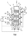
- the filter 1 comprises a closed reactor 2, here of substantially cylindrical shape, defining a longitudinal main axis X.
- the reactor 2 can also be of substantially parallelepipedal shape.
- the reactor 2 is arranged so that its main axis X is oriented substantially vertically.
- the flow of effluents to be filtered is intended to circulate in the longitudinal direction, from bottom to top, to be biologically filtered.
- the reactor 2 comprises, at the bottom, an inlet 3 of the effluents to be filtered, connected to a supply duct 4 provided with a valve 5, and a gas inlet 6 oxygenated, connected to a supply duct 7 provided with a valve 8.
- the supply of oxygenated gas, such as air, is intended to penetrate in the reactor 2 the oxygen necessary for the development of microorganisms aerobes used for filtration.
- the two Inlets 3, 6 are provided in the bottom wall 9 of the reactor 2 and allow to penetrate the effluents to be filtered and the oxygenated gas into a compartment 10.
- the inlet compartment 10 is delimited by the bottom wall 9, part of the side wall 11 of the reactor, and by an upper wall 12 extending transversely over the entire width of the reactor 2.
- the internal wall 12 is permeable to the effluents to be filtered and to the oxygenated gas, so as to allow the upward passage of effluents and gas through it.
- the openings 13a, 13c are formed in the bottom wall 9 so that ensure a good distribution of effluent and gas flows. It can be expected in addition one or more diffusers of fine bubbles of gas, for example air, allowing a homogeneous distribution of the gas within the flow of effluents to be filtered.
- the output 14 of the filtered effluents is located in the upper part of the reactor 2. According to the embodiments shown, this output 14, connected to a exhaust duct 15 filtered effluent provided with a valve 16, is provided in the side wall 11, and opens into an upper outlet stage 17 of the reactor 2. The evacuation of the filtered effluents is carried out by overflow.
- the filter 1 is of the upflow type, the gas supply oxygenated being carried out in co-current.
- the filter 1 comprises, inside the reactor 2, and interposed between the inlet 3 effluents to be filtered and the outlet 14 of filtered effluents, filtering means 18.
- the filtering means 18 comprise layers of particles of a material microporous solid forming supports, and a purifying biomass hooked onto the surface of said supports. To do this, the supports were previously seeded with aerobic microorganisms that grew on said supports and clung to it. During the implementation of the filtration, the fact that the biomass is hooked to a support makes it possible to optimize the contact between the pollutants to be treated and the micro-organisms, which leads to faster degradation of organic matter.
- the filtering means 18 have a density lower than that of the effluents to be filtered.
- the density of the effluents to be filtered depends on the quantity of pollutants present, this quantity being variable according to the origin of the effluents and the or the previous treatment (s) they have undergone.
- the reactor 2 is subdivided into four compartments superimposed on each other, according to the the longitudinal direction of the reactor, which gives the reactor a structure floors.
- the compartments are separated from one another by means of three walls 19a, 19b, 19c provided with openings, said walls extending transversely in the reactor 2 over the entire cross section thereof.
- the openings walls 19a, 19b, 19c are arranged to retain the filtering means 18, and pass the effluent streams to be filtered and gas.
- openings are distributed over the surface of the walls 19a, 19b, 19c in such a way that they ensure a good distribution of effluents and gases in the compartments of the reactor 2.
- the walls 19 provided with openings are grids mesh adapted.
- compartments thus form, in the reactor 2, on the one hand three stages of filtration respectively lower 20a, intermediate 20b, and upper 20c, and on the other hand the upper outlet stage 17.
- the upper outlet stage 17 is formed between the upper wall 21 of the reactor 2 and the upper wall 19c disposed opposite, and is free of filter media.
- the stage of lower filtration 20a is located directly above the entrance compartment 10, and it is separated by the inner wall 12.
- the stage of lower filtration 20a is delimited downwards by the lower wall 9 of the reactor 2, the inlet openings 13a of the effluents to be filtered and 13c of the inlet of gas opening directly into said lower filtration stage 20a.
- Each filtration stage 20a, 20b, 20c is provided with its own means During the upward circulation of the effluents in the reactor 2, the filtering means 18 are retained in the upper part of the filtration stage considered by the wall 19a, 19b, 19c corresponding.
- the geometry and the size of the openings of said walls are adapted to the size and the geometry of the filtering means 18.
- Each filtration stage 20a, 20b, 20c further comprises in the lower part a withdrawal outlet 22a, 22b, 22c of the excess biomass, arranged in the side wall 11 of the reactor 2.
- These outlets 22a, 22b, 22c have as their function to allow the regular evacuation of excess biomass form in each stage 20a, 20b, 20c during the filtration, this biomass not only from the continuous growth of microorganisms on the supports, but also the accumulation in each floor of suspended matter.
- each withdrawal outlet 22a, 22b, 22c is connected a conduit of withdrawal 24 provided with a valve 25.
- a recovery compartment 23a, 23b, 23c of said excess biomass can be provided, said compartment being in communication with the corresponding withdrawal conduit 24.
- the quantity and density of the filtering means 18 are such that, in withdrawal mode of the biomass surplus, the lower part of each floor into which a withdrawal outlet 22a, 22b, 22c is free of filtering means 18.
- the quantity and the density of the filtering means 18 in each filtration stage 20a, 20b, 20c are provided for said filtering means 18 float during the withdrawal of excess biomass, while being selected in their filtration stage 20a, 20b, 20c by the wall 19a, 19b, 19c corresponding.
- a free space 31 free of means filter there is, in the lower part of filtration stages 20a, 20b, 20c, a free space 31 free of means filter.
- This arrangement allows, at each filtration stage 20a, 20b, 20c, the recovery of surplus biomass avoiding simultaneous training filtering means 18 during racking which could reduce the filtration capacity of the reactor 2.
- the filtering means 18 of the upper stage 20c may not be located only in the upper part, but distributed in substantially the the entire volume of said upper stage 20c during racking.
- retaining means such as walls 19d, 19e, 19f, provided with openings, for example grids, arranged in the withdrawal ducts 24, in the vicinity of one or all the outlets bleeding 22a, 22b, 22c.
- the openings of the walls 19d, 19e, 19f or the mesh grids are such that they hold the filtering means 18 in each filtration stage 20a, 20b, 20c, and pass the excess biomass.
- At least one filtration stage 20a, 20b, 20c is provided with a means 26 for detecting the amount of excess biomass.
- the detection is done for example by the emission of a wave beam (infrared or other) and receiving it through the medium considered.
- detection 26 may be in accordance with that described in the patent application FR-A-2 731 272.
- the detection means 26 is intended, when the filter 1 is in functioning, to detect the accumulation of biomass and the predefined threshold above which the momentary shutdown of filter 1 is triggered.
- the shutdown of the filter is carried out by closing the valves 5 and 8, and the opening of the withdrawal outlet 22a, 22b or 22c of the stage concerned, by opening the corresponding valve.
- At least two filtration stages 20a, 20b, 20c comprise different filtering means 18, by the nature of their support and / or fixed biomass.
- the filtering means 18 of at least two stages 20a, 20b, 20c differ in their density, so as to adapt so optimal density of the filtering means to the amount of pollutants present in each floor, this quantity of pollutants affecting the density of the effluents to be filtered, and thus ensure that said means filtering float during racking.
- filtering means 18 whose density corresponds respectively to one and the other of the two variants exposed above.
- supports comprising density balls between 0.5 and 1, and in particular of the order of 0.7.
- each filtration stage 20a, 20b, 20c are treated effluents having different properties. Indeed, the effluents, which pass through the stages of successive filtration processes, are less and less polluted as and when they are upward circulation. And, because of the stage structure of reactor 2, it is thus possible to optimize the treatment of the effluents in each of the stages of filtration 20a, 20b, 20c, selecting the filtering means 18 the best adapted to the degree of pollution of the effluents considered, in terms of the nature of the support, biomass or density of the filtering means 18.
- the supports used for the filtering means 18 may be formed of balls, whose diameter is between 1 and 30 mm, and in particular between 4 and 10 mm. It is possible to use balls of different diameters in the different stages of filtration. These beads may be formed of plastic or mineral materials foamed, such as expanded glass, expanded clay, or expanded polystyrene. These supports have the advantage, by their geometry and the material of which they are made, to offer a surface of exchange important with the effluents to be filtered.
- the filter 1 may comprise recirculation means 27 of the filtered effluents, comprising a conduit 28 associated with a pump 29, said means being provided between the outlet 14 and the inlet 3 of the effluents. Ways 27 are arranged to recover at least a portion of the filtered effluents in reactor 2, and return this portion to the inlet 3 of reactor 2 for additional treatment.
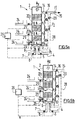
- the means recirculation devices 27 are arranged to conduct at least a part of the filtered, and therefore nitrified, effluents to a particular stage of denitrification 30, located in the lower part of the reactor 2.
- the stage of denitrification 30 to be an anoxic zone, it is then expected that the entry 6 of oxygenated gas is no longer at the same level as entry 3 of the effluent to be filtered, but above said denitrification stage 30, and by therefore above the inlet 3 of the effluents to be filtered.
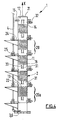
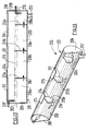
- FIG. 4 illustrates a filter 1 according to a fourth embodiment of the invention.
- the filter 1 comprises five filtration stages 20.
- the inlet 3 of effluents to be filtered and the inlet 6 of oxygenated gas are provided on the side wall 11 of the reactor 2, and open under the lower filtration stage 20a.
- the supply duct 4 effluents to be filtered extend substantially horizontally from the inlet 3, then forms a bend and extends substantially vertically along the wall This arrangement makes it possible, in particular in the event of failure of the filter 1, or if it is necessary to change the feed pump, to prevent the effluents present in the reactor 2 do not flow by gravity, desired, through the conduit 4.
- conduit 32 opening in the free space 31 from the side wall 11 of the reactor, for example substantially the opposite of the withdrawal outlet of excess biomass.
- the conduit 32 is connected to a control tool, intended for example to control the pH value of the effluents present in the filtration stage considered.
- a window 33 may be provided on the side wall 11 of the reactor 2, each filtration stage 20. This window 33 allows in particular the emission and the reception of the wave beam of the detection means 26.
- the filter 1 of FIG. 4 can be adapted to one of the configurations of FIG. to 3 (may or may not be provided: an input compartment 10, a plurality openings 13a, 13c connected to conduits 13b, 13d, a stage of denitrification 30, recirculation means 27, etc.).
- valves 5, 8 which leads to the sending in the reactor 2 on the one hand, an effluent stream to be filtered, via the inlet 3, and on the other hand of a flow of oxygenated gas, through the inlet 6.
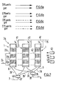
- the effluents and the gas circulate therefore upwardly, in the direction of the arrows F1 of Figure 5a.
- the effluents introduced into the reactor 2 are filtered successively by upflow in the successive filtration stages 20a, 20b, 20c.
- At least some of these filtered effluents may be fed to the reactor 2, via the recirculation duct 28 (arrow F2). These effluents are thus subjected to additional filtration which improves the degree of treatment.
- the effluents in recirculation pass through the denitrification stage 30, where they undergo a denitrification stage, in anoxic zone.
- it may be provided to periodically close the inlet 3 of the effluents to filter and the inlet 6 of oxygenated gas, by action on the valves 5 and 8, and this until formation of an anoxic zone allowing the development of micro-organisms denitrifiers, thanks to which the effluents present in the reactor 2 can undergo the denitrification process.
- the process involves mixing external gases with air sent into the reactor 2, so as to allow the oxidation of said gases.
- Smelly gases are produced by other reactors included in the station in which the filter 1 is located, the oxidation of these gases by passage through the reactor 2 allows the deodorize.
- the inlet 3 of the effluents to be filtered is closed and the inlet 6 of oxygenated gas, by acting on the valves 5 and 8, and opening the withdrawal outlet 22a, 22b, 22c of the filtration stage 20a, 20b, 20c to be washed, by opening the corresponding valve.
- the filtration stage 20a, 20b, 20c to be washed is selected according to the quantity of biomass found there, as detected by the means of detection 26.
- each filtration stage 20a, 20b, 20c is all the more important that the stage is distant from the top of reactor 2.
- the lower stages, in which the filtering means 18 have tend to clog more easily, are washed by a quantity of effluents descendants larger than the upper floors.
- the washing phase can be triggered when the detection means 26 detects a quantity of biomass greater than the threshold predefined, in at least one filtration stage.
- FIG. 7 illustrating a filtration facility 34 comprising a plurality of filters 1 arranged to operate in a parallel.
- the installation 34 comprises three filters 1 identical to the type shown in Figure 1. However, the installation 34 could have more or fewer filters. Filters could be different from each other, and correspond to any of the embodiments shown in Figures 1 to 4.
- Cutoff means 39 of the effluent feed to be filtered are provided between the conduit 4 and the conduits 36, so as to allow the closure of the effluent feed of all or part of the filters 1.
- cutting means 40 of the oxygenated gas supply are provided between the conduit 7 and the ducts 38, so as to allow the closure of the supply gas from all or part of the filters 1.
- the outlets 14 of the filtered effluents from each filter 2 are each connected to a 41, the three ducts 41 being connected to the exhaust duct 15 filtered effluents.
- the withdrawal outlets 22a, 22b, 22c of each filter 1 are connected to conduits 42, the various conduits 42 being connected to a withdrawal pipe 24.
- the installation also comprises control means respectively filtration 43, stopping the filter 44, and the recovery of biomass surplus 45.
- FIG. 8 a purification station 46 of FIGS. spent effluents.
- the raw effluents are fed via a feed conduit 107 as input of a primary clarifier 100, so as to be rid of a significant part of their suspended matter.
- the primary clarifier 100 comprises an evacuation pipe 109 of the effluents decanted connected to the inlet 3 of the effluents to be filtered from the filter 1, respectively at the inlet 35 of the effluents to be filtered from the filtration installation 34, via the conduit 4, and means for discharging sludge from the decanting.
- Sludge from primary settling is removed to a digester anaerobic sludge 200, so as to allow sludge degradation, by evacuation means, such as an exhaust duct 111, connected to the supply duct 207 in fresh sludge from the digester 200.
- the digester 200 comprises an effluent evacuation outlet, connected, via a discharge duct 209, at the effluent feed inlet at decant from the primary clarifier 100.
- the digester 200 further comprises a sludge discharge outlet connected digestion via an evacuation conduit 212 at the entrance of a thickener 48.
- the thickener 48 has an outlet 49 of the residual water connected to the effluent feed inlet to be decanted from the primary clarifier 100, possibly via the exhaust duct 209 of the effluents of the digester 200.
- the thickener 48 also has an outlet 50 of the thickened sludge.
- These sludge may be suitably packaged and treated with a view to their use, especially for soil amendment. They can also be directed to a landfill or incineration unit.
- the effluents filtered by the filter 1, or the filtration installation 34, are evacuated 15. In the case where the filter 1 is able to retain the suspended matter contained in the effluents to be filtered, the filtered effluents are rejected directly. In the opposite case, the filtered effluents are directed to the inlet of a secondary clarifier 51.
- the filter 1 also includes withdrawal outlets for evacuation biomass by withdrawal lines 24, these being able to be connected either to the inlet of the secondary clarifier 51, or when the station does not include a secondary decanter, at the inlet of the effluent feed at decant from the primary decanter 100 or at the sludge feed inlet fresh from the digester 200.
- the secondary clarifier 51 comprises means for evacuating the sludge from the decantation, connected either to the effluent feed inlet to decanting from the primary clarifier 100 via an evacuation pipe 52, possibly opening in the conduit 209, either at the feed inlet in fresh sludge from the digester 200. Some of these sludges can also be be returned to the top of filter 1 to maintain biomass at a level longed for.
- the secondary clarifier 51 comprises an exhaust duct 53 of decanted effluents.
- a first set of at least one settling panel is inclined according to a first angle ( ⁇ ) of between 15 ° and 60 °
- at least one second set of at least one settling panel is inclined according to a second angle ( ⁇ ) between 15 ° and 60 °
- the angles ( ⁇ , ⁇ ) being chosen so that, when the flow of effluents in the tank, the sludge is deposited on the surface decantation then slide towards the bottom of the tank, at least one passage 117 sludge being provided between the panels of the two together, to allow sludge collected on the upper faces panels to fall by gravity on the bottom 103 of the tank 101.
- the tank has two sets of panels arranged symmetrically by relative to the plane 113, vertical, longitudinal and median of the tank.
- the first set (left) comprises five panels 114a to 114e substantially parallel, superimposed vertically, and spaced apart from each other others of a substantially constant distance L1 of the order of 30 cm.
- the panels 114a to 114e are inclined up and down from the side wall substantially vertical from the tank to the vertical plane 113, with an angle ⁇ of the order of 45 °.
- the panels 114 have different widths I according to their distance by compared to the bottom 103 of the tank, but lengths L (parallel to flow of effluents) substantially equal.
- the panels 114 are spaced from the vertical side wall of the tank 101 a horizontal distance L2 of the order of 10 cm, for the passage of suspended matter, and the bottom 103 of a vertical height H close to 30 cm, to provide a space 115 accumulation of sludge from settling.
- the end upper panel is located at a distance d below the level 116 effluents inside the tank.
- the second set (on the right) is symmetrical of the first with respect to the plane vertical 113, and comprises five panels 114'a to 114'e.
- Horizontal spacing L3 between the first and second sets of panels is close to 30 cm, so as to provide a space 117 allowing the sludge collected on the panels to fall to the bottom by being directed and collected in area central of the bottom 103 of the tank 101.
- Means 118 for supporting and fixing the panels 114, 114 'to the tank 101 are disposed in the vicinity of the upstream and downstream ends of said panels.
- the decanter 100 comprises, in relation to the meaning effluent flow, at least a first and a second series of panels 114, 114 ', the second series being located downstream of the first series, said series each comprising at least a first and a second at least one panel, so as to further improve the extraction of sludge.
- the digester 200 comprises, according to a general definition, a tank 201 having a bottom 203 substantially horizontal, a feed pipe 207 of the sludge tank a waste water outlet 209 out of the tank, and means of evacuation 212 digested sludge out of the tank, said tank having at least one wall 213a, 213b, 213c transverse to the flow effluent, the wall defining an upstream compartment 218a, 218b, 218c and a downstream compartment 218b, 218c, 218d, so that the tank has a first upstream compartment 218a, into which the duct opens feed 207 fresh sludge, and a final compartment downstream 218d, in which the evacuation duct 209 discharges from the effluents
- the wall 213a, 213b, 213c has, at its lower part, a communication opening 216 from the upstream compartment to the downstream compartment, so as to allow the passage of sludge and the circulation of
- the digester 200 has three transverse walls respectively upstream 213a, intermediate 213b, and downstream 213c, having an annular contour 214 marrying the inner shape of the tank 201 and an upper edge 215 horizontal.
- the height of the walls is smaller than the diameter of the tank, and for example of the order of 30 cm.
- a communication opening 216 In the lower part of each wall 213a, b, c is provided a communication opening 216 having a top edge 217 annular.
- the tank 201 is thus divided longitudinally into four compartments 218a, 218b, 218c, 218d.
- the walls allow to hold in each compartment sludge formed by agglomeration of suspended matter, while excess floating material can go through an overflow of one upstream compartment with a downstream compartment, or vice versa.
- the fresh sludge introduced into the digester 200 has a concentration of dry matter less than 25 g / l. They are deposited on the bottom of the tank, under form of a thin layer, for example less than 0.5 m. It is maintained in the tank 201 a level 219 of effluents. Sludge is gradually degraded and liquefied. They then go into successive compartments through communication openings 216. The effluents flow parallel to the axis 202, taking with them the products soluble from the digestion of sludge.
Abstract
Description
L'invention concerne un filtre biologique pour le traitement des effluents usés, un procédé de filtration utilisant un tel filtre, une installation de filtration comprenant une pluralité de tels filtres, ainsi qu'une station d'épuration comprenant au moins un tel filtre ou une telle installation de filtration.The invention relates to a biological filter for the treatment of spent effluents, a filtration process using such a filter, a filtration plant comprising a plurality of such filters, as well as a treatment plant comprising at least one such filter or filtration facility.
L'invention concerne plus particulièrement un filtre biologique, ou « biofiltre », dans lequel une biomasse contenant des micro-organismes appropriés est fixée sur un support immergé. Les effluents à filtrer peuvent contenir des matières en suspension, organiques et/ou minérales, qui sont retenues dans le filtre, ainsi que des impuretés organiques dissoutes ou particulaires, qui sont transformées par l'action de la biomasse.The invention relates more particularly to a biological filter, or "biofilter", wherein a biomass containing suitable microorganisms is fixed on a submerged support. The effluents to be filtered may contain materials suspension, organic and / or mineral, which are retained in the filter, as well as dissolved or particulate organic impurities, which are transformed by the action of biomass.
Parmi les filtres biologiques existants, on connaít déjà des filtres dits « aérés », dans lesquels on introduit de l'air ou de l'oxygène pur en même temps que les effluents à filtrer, de sorte à intensifier les réactions biologiques mises en oeuvre par la biomasse. En particulier, on connaít les filtres fonctionnant à flux ascendant d'effluents, et à co-courant, ce qui signifie que les flux d'effluents et d'air sont orientés dans le même sens, de bas en haut. Cet agencement favorise notamment la rétention des matières en suspension.Among the existing biological filters, we already know so-called "ventilated" filters, in which air or pure oxygen is introduced at the same time as the effluents to be filtered, so as to intensify the biological reactions used by biomass. In particular, we know the flow-operated filters ascending effluent, and co-current, which means that effluent streams and of air are oriented in the same direction, from bottom to top. This arrangement promotes in particular the retention of suspended matter.
Pour maintenir les capacités hydrauliques et épuratoires de tels filtres, il est nécessaire d'éliminer régulièrement, par lavage, la biomasse excédentaire qui colmate le support. Cette biomasse résulte d'une part du développement des micro-organismes (biofilm) et d'autre part de la rétention des matières en suspension et de la transformation des impuretés organiques.To maintain the hydraulic and purifying capabilities of such filters, it is necessary to necessary to regularly remove, by washing, the surplus biomass clogged the support. This biomass results partly from the development of micro-organisms (biofilm) and on the other hand the retention of suspension and transformation of organic impurities.
On connaít notamment du document FR-A-2 632 947 un filtre dont la biomasse est fixée sur un support flottant, la faible densité du support étant destinée à en faciliter le lavage. Dans ce type de filtres, le lavage est effectué par injection d'eau épurée à contre-courant, et à fort débit, de sorte à détasser les matériaux formant support. Document FR-A-2,632,947 describes a filter whose biomass is fixed on a floating support, the low density of the support being intended for facilitate washing. In this type of filter, the washing is done by injection water purified against the current, and high flow, so as to loosen the materials forming a support.
Toutefois, la nécessité d'un tel lavage présente plusieurs inconvénients. En effet, les cycles réguliers de lavage consomment de l'énergie, et rendent le système de filtration complexe.However, the need for such washing has several disadvantages. In Indeed, regular washing cycles consume energy, and make the complex filtration system.
En outre, la totalité du support est lavée à chaque cycle, alors que, du fait de son hétérogénéité, il serait parfois suffisant de n'en laver qu'une fraction.In addition, the entire support is washed at each cycle, whereas, due to its heterogeneity, it would sometimes be sufficient to wash only a fraction.
Enfin, dans certains cas, il est nécessaire d'injecter dans le filtre de l'eau supplémentaire pour le lavage, ce qui peut entraíner une dilution trop importante des boues, et obliger à les reconcentrer dans un décanteur.Finally, in some cases, it is necessary to inject into the filter water extra for washing, which can cause dilution too much sludge, and force them to reconcentrate in a decanter.
L'invention propose un filtre biologique à flux ascendant, et à co-courant, agencé pour pallier ces différents inconvénients.The invention proposes an upflow biological filter and co-current, arranged to overcome these various disadvantages.
A cet effet, et selon un premier aspect, l'invention propose un filtre pour le traitement des effluents usés par voie biologique, ledit filtre étant destiné à la rétention des matières en suspension et à la transformation biologique des impuretés organiques contenues dans les effluents à filtrer, ledit filtre comprenant un réacteur dans lequel le flux d'effluents à filtrer est prévu pour circuler de bas en haut, ledit réacteur comprenant :
- en partie basse, une entrée des effluents à filtrer et une entrée de gaz oxygéné ;
- et, en partie haute, une sortie des effluents filtrés ;
- des moyens filtrants comprenant des couches de particules d'un matériau solide formant supports et une biomasse accrochée sur la surface desdits supports, lesdits moyens filtrants ayant une densité inférieure à la densité des effluents à filtrer et étant interposés entre l'entrée des effluents à filtrer et la sortie des effluents filtrés.
- in the lower part, an inlet of the effluents to be filtered and an inlet of oxygenated gas;
- and, at the top, an outlet of the filtered effluents;
- filtering means comprising layers of particles of a solid material forming supports and a biomass hung on the surface of said supports, said filtering means having a density lower than the density of the effluents to be filtered and being interposed between the inlet of the effluents to be filtered and the outlet of the filtered effluents.
Selon une définition générale de l'invention, le réacteur est subdivisé en au moins trois compartiments superposés formant étages au moyen d'au moins deux parois munies d'ouvertures, lesdites ouvertures étant agencées pour retenir les moyens filtrants, de sorte à former dans le réacteur au moins deux étages de filtration et un étage supérieur de sortie, la sortie des effluents filtrés débouchant dans l'étage supérieur de sortie, chaque étage de filtration étant pourvu d'une couche de ses propres moyens filtrants, et comprenant, en partie inférieure, une sortie de soutirage de la biomasse excédentaire, la quantité et la densité des moyens filtrants dans chaque étage de étant telles que, en mode soutirage, la partie inférieure d'au moins le ou les étages inférieurs dans laquelle débouche la sortie de soutirage est exempte de moyens filtrants, de manière à permettre la récupération de la biomasse excédentaire.According to a general definition of the invention, the reactor is subdivided into minus three superimposed compartments forming floors by means of at least two walls provided with openings, said openings being arranged to retain the filtering means, so as to form in the reactor at least two filtration stages and an upper outlet stage, the output of filtered effluents opening into the upper outlet stage, each filtration stage being provided with a layer of its own filtering means, and comprising, in part lower, a withdrawal output of excess biomass, the quantity and density of the filtering means in each stage of being such that, in racking, the lower part of at least the lower stage or floors in which opens the withdrawal outlet is free of filtering means, to allow recovery of excess biomass.
Le filtre selon l'invention présente ainsi plusieurs étages de filtration qui peuvent être débarrassés indépendamment les uns des autres de leur biomasse excédentaire, ce qui permet de mettre en oeuvre le lavage de façon sélective, en déterminant, au fur et à mesure du procédé de filtration, quelle fraction du support nécessite d'être lavée.The filter according to the invention thus has several filtration stages which can be discarded independently of each other from their biomass excessively, which makes it possible to carry out the washing in a selective manner, by determining, as and when the filtration process, which fraction of the support needs to be washed.
La présence de plusieurs étages de filtration présente également l'avantage de permettre une filtration modulable, en adaptant de façon optimale le support de biomasse dans chaque étage de filtration, ce qui résulte en une efficacité accrue du processus de filtration.The presence of several filtration stages also has the advantage of allow a modular filtration, optimally adapting the support of biomass in each filtration stage, resulting in efficiency increased filtration process.
Selon une réalisation possible, au moins deux étages de filtration comprennent des moyens filtrants différents, de par la nature de leur support et/ou de la biomasse fixée, et diffèrent par exemple par leur densité.According to one possible embodiment, at least two filtration stages comprise different filtering means, by the nature of their support and / or the fixed biomass, and differ for example in their density.
Selon un deuxième aspect, l'invention concerne un procédé de filtration biologique des effluents usés mettant en oeuvre un filtre tel que précédemment décrit, ledit procédé comportant une phase de filtration comprenant les étapes consistant à :
- alimenter le réacteur en effluents à filtrer et en gaz oxygéné, selon un courant ascendant, par l'entrée des effluents à filtrer et l'entrée de gaz oxygéné, respectivement ;
- faire circuler ledit gaz et lesdits effluents de façon ascendante dans les différents étages de filtration successifs, de sorte à filtrer lesdits effluents ;
- récupérer les effluents filtrés par la sortie du réacteur.
- supplying the reactor with effluent to be filtered and oxygenated gas, according to an updraft, through the inlet of the effluents to be filtered and the inlet of oxygenated gas, respectively;
- circulating said gas and said effluents ascendingly in the different successive filtration stages, so as to filter said effluents;
- recover the effluents filtered by the outlet of the reactor.
Le procédé de filtration comporte en outre une phase de lavage d'au moins un étage de filtration, au cours de laquelle :
- on ferme l'entrée des effluents à filtrer et l'entrée de gaz oxygéné du réacteur ;
- puis on ouvre la sortie de soutirage de l'étage à laver, de sorte à entraíner la biomasse excédentaire par vidange, par différence de pression entre le haut du réacteur et ladite sortie de soutirage.
- the inlet of the effluents to be filtered and the inlet of oxygen gas from the reactor are closed;
- then opening the withdrawal outlet of the stage to be washed, so as to cause excess biomass drain, pressure difference between the top of the reactor and said withdrawal outlet.
Selon un troisième aspect, l'invention a pour objet une installation de filtration, comprenant une pluralité de filtres tels que précédemment décrits, disposés de sorte à fonctionner en parallèle.According to a third aspect, the subject of the invention is a filtration installation, comprising a plurality of filters as previously described, disposed of so to operate in parallel.
L'installation comprend une entrée des effluents à filtrer connectée à l'entrée des effluents à filtrer de chacun des filtres, une entrée de gaz oxygéné, connectée à l'entrée de gaz oxygéné de chacun des filtres, une sortie des effluents filtrés connectée à la sortie de chacun des filtres, et au moins une sortie de soutirage connectée aux sorties de soutirage de chacun des filtres.The installation includes an effluent inlet to be filtered connected to the inlet effluents to be filtered from each of the filters, an oxygenated gas inlet, connected to the oxygenated gas inlet of each of the filters, an output of filtered effluents connected to the outlet of each of the filters, and at least one withdrawal outlet connected to the withdrawal outlets of each of the filters.
L'installation comprend en outre des moyens de coupure sélectifs de l'alimentation en effluents à filtrer et en gaz oxygéné de chacun des filtres, des moyens de commande de la filtration, de l'arrêt et de la récupération de la biomasse excédentaire, de sorte à permettre simultanément la filtration des effluents à filtrer par un nombre minimal de filtres, et l'arrêt des autres filtres en vue de la récupération de la biomasse excédentaire et/ou de et la dénitrification d'au moins une partie des effluents filtrés dans lesdits autres filtres.The installation also includes means for selectively supply of effluents to be filtered and of oxygenated gas from each of the filters, control means for filtering, stopping and recovering the excess biomass so that the filtration of effluent to be filtered by a minimum number of filters, and stopping the other filters in view of the recovery of excess biomass and / or de and denitrification at least a portion of the effluents filtered in said other filters.
Enfin, selon un quatrième aspect, l'invention concerne une station d'épuration d'effluents usés comprenant au moins un tel filtre ou une telle installation de filtration. Finally, according to a fourth aspect, the invention relates to a purification plant spent effluent comprising at least one such filter or such a plant of filtration.
D'autres objets et avantages de l'invention apparaítront au cours de la description qui suit, faite en référence aux figures annexées, dans lesquelles :
- les figures 1 à 4 sont des vues schématiques en coupe verticale longitudinale d'un filtre selon l'invention, respectivement selon un premier, un deuxième, un troisième et un quatrième modes de réalisation ;
- les figures 5a et 5b sont des vues schématiques en coupe verticale longitudinale du filtre de la figure 1, représentant la mise en oeuvre du procédé de traitement des effluents usés pendant la phase de filtration, (figure 5a), et pendant la phase de lavage (figure 5b) ;
- les figures 6a, 6b, 6c et 6d sont des schémas montrant les différentes possibilités d'envoi des flux d'effluents et de gaz ;
- la figure 7 est une représentation schématique d'une installation de filtration selon l'invention, comprenant trois filtres tels que celui représenté sur la figure 1, lesdits filtres fonctionnant en parallèle et étant représentés en coupe verticale longitudinale ;
- la figure 8 est une représentation schématique d'une station d'épuration selon l'invention, comprenant notamment un filtre ou une installation de filtration, un décanteur et un digesteur anaérobie de boues, illustrant en outre les étapes d'un procédé de traitement des effluents usés dans ladite station d'épuration ;
- la figure 9 est une vue schématique en coupe transversale d'un mode de réalisation possible d'un décanteur prévu dans la station d'épuration ;
- la figure 10 est une vue schématique en coupe du décanteur de la figure 9, selon la ligne AA ;
- la figure 11 est une vue en coupe du décanteur de la figure 9, selon la ligne BB de la figure 10 ;
- la figure 12 est une vue schématique en coupe, selon un plan vertical longitudinal médian, d'un digesteur prévu dans la station d'épuration, selon un mode de réalisation possible ;
- la figure 13 est une vue schématique en perspective du digesteur de la figure 12, vu selon la même coupe.
- Figures 1 to 4 are schematic views in longitudinal vertical section of a filter according to the invention, respectively according to a first, a second, a third and a fourth embodiments;
- FIGS. 5a and 5b are diagrammatic views in longitudinal vertical section of the filter of FIG. 1, showing the implementation of the process for treating spent effluents during the filtration phase, (FIG. 5a), and during the washing phase (FIG. Figure 5b);
- Figures 6a, 6b, 6c and 6d are diagrams showing the different possibilities of sending effluent and gas streams;
- Figure 7 is a schematic representation of a filtration installation according to the invention, comprising three filters such as that shown in Figure 1, said filters operating in parallel and being shown in longitudinal vertical section;
- FIG. 8 is a diagrammatic representation of a purification plant according to the invention, comprising in particular a filter or filtration plant, a decanter and an anaerobic sludge digester, further illustrating the steps of a process for the treatment of spent effluents in said treatment plant;
- Figure 9 is a schematic cross-sectional view of a possible embodiment of a decanter provided in the treatment plant;
- Figure 10 is a schematic sectional view of the decanter of Figure 9, along the line AA;
- Figure 11 is a sectional view of the decanter of Figure 9, along the line BB of Figure 10;
- Figure 12 is a schematic sectional view along a median longitudinal vertical plane of a digester provided in the purification plant, according to a possible embodiment;
- Figure 13 is a schematic perspective view of the digester of Figure 12, seen according to the same section.
On se rapporte tout d'abord aux figures 1 à 3 qui représentent un filtre
biologique 1, selon différents modes de réalisation.We first refer to Figures 1 to 3 which represent a
Le filtre 1 est destiné au traitement par voie biologique des effluents usés. Il est
destiné en particulier au traitement d'effluents ayant subi au préalable une
étape de décantation destinée à éliminer une part importante de leurs matières
en suspension.
Un tel filtre assure plusieurs fonctions épuratrices en combinaison :
- la transformation biologique des impuretés organiques dissoutes dans les effluents à filtrer, sous l'action de micro-organismes aérobies épurateurs qui permettent d'une part de diminuer la pollution carbonée par transformation du carbone organique en carbone minéral, et d'autre part de transformer l'azote organique par nitrification et de l'éliminer par dénitrification ;
- la rétention des matières en suspension, par passage des effluents à filtrer au travers de moyens filtrants ;
- l'élimination des matières en suspension organiques.
- the biological transformation of dissolved organic impurities in the effluents to be filtered, under the action of aerobic micro-organisms purifying which on the one hand to reduce the carbon pollution by transformation of organic carbon into mineral carbon, and on the other hand to transform organic nitrogen by nitrification and remove it by denitrification;
- the retention of suspended solids by passing the effluents to be filtered through filtering means;
- removal of organic suspended solids.
Comme il sera exposé, un tel filtre 1 peut être inclus dans une installation qui en
comporte plusieurs et, plus généralement, dans une station d'épuration
comprenant en outre au moins un décanteur et un digesteur anaérobie de
boues.As it will be exposed, such a
Le filtre 1 comprend un réacteur fermé 2, ici de forme sensiblement cylindrique,
définissant un axe principal longitudinal X. Le réacteur 2 peut également être de
forme sensiblement parallélépipédique. Le réacteur 2 est disposé de sorte que
son axe principal X soit orienté sensiblement verticalement.The
Dans le réacteur 2, le flux d'effluents à filtrer est prévu pour circuler dans la
direction longitudinale, de bas en haut, en vue d'être filtré biologiquement.In
Le réacteur 2 comprend, en partie basse, une entrée 3 des effluents à filtrer,
reliée à un conduit d'alimentation 4 muni d'une vanne 5, et une entrée 6 de gaz
oxygéné, reliée à un conduit d'alimentation 7 muni d'une vanne 8.
L'alimentation en gaz oxygéné, tel que de l'air, est destinée à faire pénétrer
dans le réacteur 2 l'oxygène nécessaire au développement de micro-organismes
aérobies utilisés pour la filtration.The
Selon un premier mode de réalisation, représenté sur la figure 1, les deux
entrées 3, 6 sont prévues dans la paroi inférieure 9 du réacteur 2 et permettent
de faire pénétrer les effluents à filtrer et le gaz oxygéné dans un compartiment
d'entrée 10. Le compartiment d'entrée 10 est délimité par la paroi inférieure 9,
une partie de la paroi latérale 11 du réacteur, et par une paroi supérieure
interne 12 s'étendant transversalement, sur toute la largeur du réacteur 2. La
paroi interne 12 est perméable aux effluents à filtrer et au gaz oxygéné, de
sorte à autoriser le passage ascendant des effluents et du gaz à travers elle.According to a first embodiment, represented in FIG. 1, the two
La présence d'un tel compartiment d'entrée 10 a pour fonction de permettre une
bonne répartition des flux d'effluents à filtrer et de gaz oxygéné au sein du
réacteur 2, quels que soient les débits d'entrée des effluents et du gaz. Par
conséquent, on obtient un traitement optimal des effluents.The presence of such an
Toutefois, on peut également prévoir que les flux d'effluents à filtrer et de gaz pénètrent dans le réacteur 2 sans passer par un tel compartiment d'entrée 10. A cet effet, selon un deuxième mode de réalisation, représenté sur la figure 2, la paroi inférieure 9 du réacteur 2 comprend :
- d'une part une pluralité d'ouvertures 13a,
formant entrée 3, reliées chacune à un conduit 13b, lesdits conduits 13b étant eux-mêmes reliés au conduit d'alimentation 4 en effluents à filtrer ; - d'autre part une pluralité d'ouvertures 13c,
formant entrée 6, reliées chacune àun conduit 13d,lesdits conduits 13d étant eux-mêmes reliés auconduit d'alimentation 7 en gaz oxygéné.
- on the one hand a plurality of openings 13a, forming
inlet 3, each connected to a conduit 13b, said ducts 13b themselves being connected to the supply duct 4 effluent to be filtered; - on the other hand a plurality of
openings 13c, forming aninlet 6, each connected to aduct 13d, saidducts 13d being themselves connected to thesupply duct 7 in oxygenated gas.
Les ouvertures 13a, 13c sont ménagées dans la paroi inférieure 9 de sorte à
assurer une bonne répartition des flux d'effluents et de gaz. Il peut être prévu
en outre un ou plusieurs diffuseurs de fines bulles de gaz, par exemple d'air,
permettant une répartition homogène du gaz au sein du flux d'effluents à filtrer.The
La sortie 14 des effluents filtrés est quant à elle située en partie haute du
réacteur 2. Selon les réalisations représentées, cette sortie 14, reliée à un
conduit d'évacuation 15 des effluents filtrés muni d'une vanne 16, est ménagée
dans la paroi latérale 11, et débouche dans un étage supérieur de sortie 17 du
réacteur 2. L'évacuation des effluents filtrés est effectuée par surverse.The
Ainsi, le filtre 1 est du type à flux d'effluents ascendant, l'alimentation en gaz
oxygéné étant réalisée à co-courant.Thus, the
Le filtre 1 comprend, à l'intérieur du réacteur 2, et interposés entre l'entrée 3
des effluents à filtrer et la sortie 14 des effluents filtrés, des moyens filtrants 18.
Les moyens filtrants 18 comprennent des couches de particules d'un matériau
solide microporeux formant supports, et une biomasse épuratrice accrochée sur
la surface desdits supports. Pour ce faire, les supports ont été préalablement
ensemencés avec des micro-organismes aérobies qui se sont développés sur
lesdits supports et s'y sont accrochés. Lors de la mise en oeuvre de la filtration,
le fait que la biomasse est accrochée à un support permet d'optimiser le contact
entre les matières polluantes à traiter et les micro-organismes, ce qui conduit à
une dégradation plus rapide de la matière organique.The
Les moyens filtrants 18 ont une densité inférieure à celle des effluents à filtrer. La densité des effluents à filtrer dépend de la quantité de matières polluantes présentes, cette quantité étant variable selon la provenance des effluents et le ou les traitement(s) préalable(s) qu'ils ont subi.The filtering means 18 have a density lower than that of the effluents to be filtered. The density of the effluents to be filtered depends on the quantity of pollutants present, this quantity being variable according to the origin of the effluents and the or the previous treatment (s) they have undergone.
Concernant la densité des moyens filtrants 18, plusieurs variantes sont possibles :
- selon une première variante, la densité des moyens filtrants 18 est suffisamment faible, par rapport à la densité des effluents à filtrer, pour que, lors de la circulation des effluents à filtrer, lesdits moyens filtrants flottent toujours, en présence ou en absence de gaz ;
- selon une deuxième variante, la densité des moyens filtrants 18 a une valeur plus élevée que précédemment, et intermédiaire entre la densité du mélange effluents à filtrer - gaz et la densité, plus importante, des effluents à filtrer seuls. Ainsi, lors de la circulation des effluents à filtrer, les moyens filtrants 18 ne flottent qu'en absence de gaz dans le réacteur 2.
- according to a first variant, the density of the filtering means 18 is sufficiently small, relative to the density of the effluents to be filtered, so that, during the circulation of the effluents to be filtered, said filtering means always float, in the presence or absence of gas ;
- according to a second variant, the density of the filtering means 18 has a value higher than previously, and intermediate between the density of the effluent mixture to be filtered - gas and the higher density of the effluents to be filtered alone. Thus, during the circulation of the effluents to be filtered, the filtering means 18 float in the absence of gas in the
reactor 2.
Dans les modes de réalisation représentées sur les figures 1 à 3, le réacteur 2
est subdivisé en quatre compartiments superposés les uns aux autres, selon la
direction longitudinale du réacteur, ce qui confère au réacteur une structure en
étages.In the embodiments shown in FIGS. 1 to 3, the
Les compartiments sont séparés les uns des autres au moyen de trois parois
19a, 19b, 19c munies d'ouvertures, lesdites parois s'étendant transversalement
dans le réacteur 2 sur toute la section transversale de celui-ci. Les ouvertures
des parois 19a, 19b, 19c sont agencées pour retenir les moyens filtrants 18, et
laisser passer les flux d'effluents à filtrer et de gaz. En particulier, les ouvertures
sont réparties sur la surface des parois 19a, 19b, 19c de façon telle qu'elles
assurent une bonne distribution des effluents et du gaz dans les compartiments
du réacteur 2. Par exemple, les parois 19 munies d'ouvertures sont des grilles
de maille adaptée.The compartments are separated from one another by means of three
Ces compartiments forment ainsi, dans le réacteur 2, d'une part trois étages de
filtration respectivement inférieur 20a, intermédiaire 20b, et supérieur 20c, et
d'autre part l'étage supérieur de sortie 17. L'étage supérieur de sortie 17 est
formé entre la paroi supérieure 21 du réacteur 2 et la paroi 19c supérieure
disposée en regard, et est exempt de moyens filtrants.These compartments thus form, in the
Selon le premier mode de réalisation, représenté sur la figure 1, l'étage de
filtration inférieur 20a est situé directement au-dessus du compartiment d'entrée
10, et il en est séparé par la paroi interne 12. According to the first embodiment, represented in FIG. 1, the stage of
Selon le deuxième mode de réalisation, représenté sur la figure 2, l'étage de
filtration inférieur 20a est délimité vers le bas par la paroi inférieure 9 du
réacteur 2, les ouvertures 13a d'entrée des effluents à filtrer et 13c d'entrée de
gaz débouchant directement dans ledit étage de filtration inférieur 20a.According to the second embodiment, represented in FIG. 2, the stage of
Chaque étage de filtration 20a, 20b, 20c est pourvu de ses propres moyens
filtrants 18. Lors de la circulation ascendante des effluents dans le réacteur 2,
les moyens filtrants 18 sont retenus en partie supérieure de l'étage de filtration
considéré par la paroi 19a, 19b, 19c correspondante. A cet effet, la géométrie et
la taille des ouvertures desdites parois sont adaptées à la taille et à la
géométrie des moyens filtrants 18.Each
Chaque étage de filtration 20a, 20b, 20c comprend en outre en partie inférieure
une sortie de soutirage 22a, 22b, 22c de la biomasse excédentaire, ménagée
dans la paroi latérale 11 du réacteur 2. Ces sorties 22a, 22b, 22c ont pour
fonction de permettre l'évacuation régulière de la biomasse excédentaire qui se
forme dans chaque étage 20a, 20b, 20c au cours de la filtration, cette biomasse
provenant non seulement de la croissance en continu des micro-organismes
sur les supports, mais également de l'accumulation dans chaque étage des
matières en suspension.Each
A chaque sortie de soutirage 22a, 22b, 22c est connecté un conduit de
soutirage 24 muni d'une vanne 25. Un compartiment de récupération 23a, 23b,
23c de ladite biomasse excédentaire peut être prévu, ledit compartiment étant
en communication avec le conduit de soutirage 24 correspondant.At each
Dans chaque étage de filtration 20a, 20b, 20c, la quantité et la densité des
moyens filtrants 18 sont telles que, en mode soutirage de la biomasse
excédentaire, la partie inférieure de chaque étage dans laquelle débouche une
sortie de soutirage 22a, 22b, 22c, est exempte de moyens filtrants 18.In each
Pour ce faire, la quantité et la densité des moyens filtrants 18 dans chaque
étage de filtration 20a, 20b, 20c sont prévues pour que lesdits moyens filtrants
18 flottent lors du soutirage de la biomasse excédentaire, tout en étant retenus
dans leur étage de filtration 20a, 20b, 20c par la paroi 19a, 19b, 19c
correspondante. Ainsi, lors du soutirage, il existe, en partie inférieure des
étages de filtration 20a, 20b, 20c, un espace libre 31 exempt de moyens
filtrants.For this purpose, the quantity and the density of the filtering means 18 in each
Cet agencement permet, à chaque étage de filtration 20a, 20b, 20c, la
récupération de la biomasse excédentaire en évitant l'entraínement simultané
des moyens filtrants 18 lors du soutirage qui risquerait de diminuer les
capacités de filtration du réacteur 2.This arrangement allows, at each
En variante, les moyens filtrants 18 de l'étage supérieur 20c peuvent ne pas être situés uniquement en partie supérieure, mais répartis dans sensiblement la totalité du volume dudit étage supérieur 20c, lors du soutirage.As a variant, the filtering means 18 of the upper stage 20c may not be located only in the upper part, but distributed in substantially the the entire volume of said upper stage 20c during racking.
En outre, pour s'assurer que les moyens filtrants 18 ne sortent pas du réacteur
2 au moment du soutirage, on peut prévoir des moyens de retenue tels que des
parois 19d, 19e, 19f, munies d'ouvertures, par exemple des grilles, disposées
dans les conduits de soutirage 24, au voisinage d'une ou de toutes les sorties
de soutirage 22a, 22b, 22c. Les ouvertures des parois 19d, 19e, 19f ou la maille
des grilles sont telles qu'elles retiennent les moyens filtrants 18 dans chaque
étage de filtration 20a, 20b, 20c, et laissent passer la biomasse excédentaire.In addition, to ensure that the filtering means 18 do not leave the
Selon un mode de réalisation, au moins un étage de filtration 20a, 20b, 20c est
pourvu d'un moyen de détection 26 de la quantité de biomasse excédentaire.
La détection se fait par exemple par l'émission d'un faisceau d'onde (infrarouge
ou autre) et la réception de celui-ci à travers le milieu considéré. Un tel moyen
de détection 26 peut être conforme à celui décrit dans la demande de brevet
FR-A-2 731 272. Le moyen de détection 26 est destiné, lorsque le filtre 1 est en
fonctionnement, à détecter l'accumulation de biomasse et le dépassement d'un
seuil prédéfini au-delà duquel l'arrêt momentané du filtre 1 est déclenché.
L'arrêt du filtre est effectué par la fermeture des vannes 5 et 8, et l'ouverture de
la sortie de soutirage 22a, 22b ou 22c de l'étage concerné, par ouverture de la
vanne 25 correspondante.According to one embodiment, at least one
Selon une réalisation possible, au moins deux étages de filtration 20a, 20b, 20c
comprennent des moyens filtrants 18 différents, de par la nature de leur support
et/ou de la biomasse fixée.According to one possible embodiment, at least two
On peut également prévoir que les moyens filtrants 18 d'au moins deux étages
de filtration 20a, 20b, 20c diffèrent par leur densité, de sorte à adapter de façon
optimale la densité des moyens filtrants à la quantité de matières polluantes
présente dans chaque étage, cette quantité de matières polluantes influant sur
la densité des effluents à filtrer, et faire ainsi en sorte que lesdits moyens
filtrants flottent lors du soutirage. En particulier, on peut choisir, pour au moins
deux étages de filtration, des moyens filtrants 18 dont la densité correspond
respectivement à l'une et à l'autre des deux variantes exposées plus haut. Par
exemple, on peut utiliser des supports comprenant des billes de densité
comprise entre 0,5 et 1, et notamment de l'ordre de 0,7.It can also be provided that the filtering means 18 of at least two
Dans chaque étage de filtration 20a, 20b, 20c sont traités des effluents ayant
des propriétés différentes. En effet, les effluents, qui passent par les étages de
filtration successifs, sont de moins en moins pollués au fur et à mesure de leur
circulation ascendante. Et, de par la structure en étages du réacteur 2, il est
ainsi possible d'optimiser le traitement des effluents dans chacun des étages de
filtration 20a, 20b, 20c, en sélectionnant les moyens filtrants 18 les mieux
adaptés au degré de pollution des effluents considérés, en termes de nature du
support, de biomasse ou encore de densité des moyens filtrants 18.In each
Les supports utilisés pour les moyens filtrants 18 peuvent être formés de billes, dont le diamètre est compris entre 1 et 30 mm, et notamment entre 4 et 10 mm. On peut utiliser des billes de diamètres différents dans les différents étages de filtration. Ces billes peuvent être formées de matières plastiques ou minérales expansées, telles que du verre expansé, de l'argile expansée, ou du polystyrène expansé. Ces supports présentent l'avantage, de par leur géométrie et le matériau dont ils sont constitués, d'offrir une surface d'échange importante avec les effluents à filtrer.The supports used for the filtering means 18 may be formed of balls, whose diameter is between 1 and 30 mm, and in particular between 4 and 10 mm. It is possible to use balls of different diameters in the different stages of filtration. These beads may be formed of plastic or mineral materials foamed, such as expanded glass, expanded clay, or expanded polystyrene. These supports have the advantage, by their geometry and the material of which they are made, to offer a surface of exchange important with the effluents to be filtered.
En outre, le filtre 1 peut comprendre des moyens de recirculation 27 des
effluents filtrés, comportant un conduit 28 associé à une pompe 29, lesdits
moyens étant prévus entre la sortie 14 et l'entrée 3 des effluents. Les moyens
27 sont agencés pour récupérer au moins une partie des effluents filtrés en
sortie du réacteur 2, et renvoyer cette partie à l'entrée 3 du réacteur 2 pour
traitement supplémentaire.In addition, the
Selon un troisième mode de réalisation, représenté sur la figure 3, les moyens
de recirculation 27 sont agencés pour conduire au moins une partie des
effluents filtrés, et par conséquent nitrifiés, vers un étage particulier de
dénitrification 30, situé en partie inférieure du réacteur 2. L'étage de
dénitrification 30 devant être une zone anoxique, il est alors prévu que l'entrée
6 de gaz oxygéné soit située non plus au même niveau que l'entrée 3 des
effluents à filtrer, mais au-dessus dudit étage de dénitrification 30, et par
conséquent au-dessus de l'entrée 3 des effluents à filtrer.According to a third embodiment, represented in FIG. 3, the
On se rapporte à présent à la figure 4, qui illustre un filtre 1 selon un quatrième
mode de réalisation de l'invention.Referring now to FIG. 4, which illustrates a
Le filtre 1 comprend cinq étages de filtration 20. L'entrée 3 d'effluents à filtrer et
l'entrée 6 de gaz oxygéné sont prévues sur la paroi latérale 11 du réacteur 2, et
débouchent sous l'étage inférieur de filtration 20a. Le conduit d'alimentation 4
des effluents à filtrer s'étend sensiblement horizontalement depuis l'entrée 3,
puis forme un coude et s'étend sensiblement verticalement le long de la paroi
latérale 11. Cet agencement permet, notamment en cas de panne du filtre 1, ou
en cas de nécessité de changement de pompe d'alimentation, d'éviter que les
effluents présents dans le réacteur 2 ne s'écoulent par gravité, de façon non
souhaitée, à travers le conduit 4. The
En outre, il peut être prévu à un ou plusieurs étages un conduit 32 débouchant
dans l'espace libre 31 depuis la paroi latérale 11 du réacteur, par exemple
sensiblement à l'opposé de la sortie de soutirage de la biomasse excédentaire.
Le conduit 32 est relié à un outil de contrôle, destiné par exemple à contrôler la
valeur du pH des effluents présents dans l'étage de filtration considéré.In addition, it can be provided on one or more floors a
Une fenêtre 33 peut être ménagée sur la paroi latérale 11 du réacteur 2, à
chaque étage de filtration 20. Cette fenêtre 33 permet notamment l'émission et
la réception du faisceau d'onde du moyen de détection 26.A
A titre d'exemple, les caractéristiques du filtre 1 représenté sur la figure 4 peuvent être les suivantes (filtre utilisé dans une station d'épuration, pour le traitement des effluents usés à dominante domestique ayant subi un traitement préalable par décantation primaire) :
- hauteur totale du réacteur : 3,33 m ;
- hauteur d'un étage de filtration : 0,56 m ;
- hauteur occupée par les moyens filtrants dans un étage : 0,36 m ;
- nature des moyens filtrants : billes d'argile expansée ;
- diamètre des billes : entre 4 et 10 mm ;
- masse volumique des billes : 0,7 kg/m3 ;
- pour une surface d'un étage de filtration de 1 m2 (le diamètre d'un étage,
dans le cas d'un filtre cylindrique, pouvant être de 3 à 4 m, voire
davantage) :
- débit des effluents à filtrer : 140 I/h ;
- débit du gaz oxygéné : 1220 I/h ;
- nature du gaz oxygéné utilisé : 80% N2 + 20% O2.
- total reactor height: 3.33 m;
- height of a filtration stage: 0.56 m;
- height occupied by the filtering means in a stage: 0.36 m;
- nature of the filtering means: expanded clay beads;
- diameter of the balls: between 4 and 10 mm;
- density of the balls: 0.7 kg / m 3 ;
- for a surface of a filtration stage of 1 m 2 (the diameter of a stage, in the case of a cylindrical filter, which may be 3 to 4 m or more):
- flow of the effluents to be filtered: 140 l / h;
- flow of the oxygenated gas: 1220 I / h;
- nature of the oxygenated gas used: 80% N 2 + 20% O 2 .
Les caractéristiques des effluents en entrée de la station (décrite ci-après) et de ce filtre, et en sortie du filtre sont les suivantes :
- DCO à l'entrée de la station : 800 mg/l ;
- DCO à l'entrée du filtre : 560 mg/l ;
- charge hydraulique à l'entrée du filtre : 0,6 m3 / m2.H ;
- en sortie du filtre (sans étape de dénitrification) :
- DCO ≤ 125 mg/l ;
- DBO5 ≤ 25 mg/l ;
- matières en suspension ≤ 30 mg/l ;
- N-NTK ≤ 10 mg/l
- COD at the entrance of the station: 800 mg / l;
- COD at the inlet of the filter: 560 mg / l;
- hydraulic load at the inlet of the filter: 0.6 m 3 / m 2 .H;
- at the filter outlet (without denitrification stage):
- COD ≤ 125 mg / l;
- BOD 5 ≤ 25 mg / l;
- suspended solids ≤ 30 mg / l;
- N-NTK ≤ 10 mg / l
Le filtre 1 de la figure 4 peut être adapté à l'une des configurations des figures 1
à 3 (peuvent être ou non prévus : un compartiment d'entrée 10, une pluralité
d'ouvertures 13a, 13c reliées à des conduits 13b, 13d, un étage de
dénitrification 30, des moyens de recirculation 27, etc.).The
On décrit à présent le procédé de filtration biologique d'effluents utilisant un filtre selon l'invention, en relation avec les figures 5a, 5b et 6a à 6d.The biological effluent filtration process using a filter according to the invention, in connection with Figures 5a, 5b and 6a to 6d.
On s'intéresse tout d'abord à la phase de filtration (figure 5a).We first look at the filtration phase (Figure 5a).
Tout d'abord, on ouvre les vannes 5, 8, ce qui conduit à l'envoi dans le
réacteur 2 d'une part d'un flux d'effluents à filtrer, par l'entrée 3, et d'autre part
d'un flux de gaz oxygéné, par l'entrée 6. Les effluents et le gaz circulent donc
de façon ascendante, dans le sens des flèches F1 de la figure 5a.First, we open the
Plusieurs possibilités sont envisageables, en ce qui concerne l'envoi des flux d'effluents à filtrer et de gaz oxygéné, comme représenté de façon schématique sur les figures 6a à 6d :
- selon une première variante (figure 6a), les alimentations en effluents à filtrer et en gaz oxygéné sont réalisées de façon continue (représentation en traits pleins) ;
- selon une deuxième variante (figure 6b), l'alimentation en effluents est continue et l'alimentation en gaz discontinue (représentation en pointillés) ;
- selon une troisième variante (figure 6c), l'alimentation en effluents est discontinue et l'alimentation en gaz continue ;
- selon une quatrième variante (figure 6d), les alimentations en effluents et en gaz sont discontinues, et simultanées ou non.
- according to a first variant (Figure 6a), the effluent feeds to be filtered and oxygenated gas are continuously produced (solid line representation);
- according to a second variant (Figure 6b), the effluent supply is continuous and the discontinuous gas supply (dashed representation);
- according to a third variant (Figure 6c), the effluent supply is discontinuous and the gas supply continues;
- according to a fourth variant (Figure 6d), the effluent and gas feeds are discontinuous, and simultaneous or not.
Dans le cas d'une alimentation discontinue en effluents, on peut prévoir de
régler cette alimentation de sorte que le réacteur 2 ne reçoive un certain volume
d'effluents à filtrer que lorsque le volume précédent l'a bien été. Cela permet
d'obtenir une meilleure répartition des effluents dans le réacteur, ainsi qu'une
meilleure épuration.In the case of a discontinuous feed of effluents, it is possible to provide
set this power supply so that the
Les effluents introduits dans le réacteur 2 sont filtrés successivement par
circulation ascendante dans les étages de filtration successifs 20a, 20b, 20c.The effluents introduced into the
Lorsque les effluents débouchent dans l'étage supérieur 17, ils sont évacués
par la sortie 14 et le conduit d'évacuation 15 (flèche F'1).When the effluents emerge in the
Le cas échéant, au moins une partie de ces effluents filtrés peut être à nouveau
acheminée vers le réacteur 2, via le conduit de recirculation 28 (flèche F2). Ces
effluents subissent ainsi une filtration supplémentaire qui permet d'améliorer le
degré de traitement. Dans le cas du filtre représenté sur la figure 3, les effluents
en recirculation passent par l'étage de dénitrification 30, où ils subissent une
étape de dénitrification, en zone anoxique.Where appropriate, at least some of these filtered effluents may be
fed to the
En variante, il peut être prévu de fermer périodiquement l'entrée 3 des effluents
à filtrer et l'entrée 6 de gaz oxygéné, par action sur les vannes 5 et 8, et ce
jusqu'à formation d'une zone anoxique permettant le développement de micro-organismes
dénitrifiants, grâce auxquels les effluents présents dans le
réacteur 2 peuvent subir le processus de dénitrification.Alternatively, it may be provided to periodically close the
Dans le cas où le gaz oxygéné comprend de l'air additionné de gaz à oxyder, le
procédé prévoit de mélanger des gaz extérieurs avec de l'air envoyé dans le
réacteur 2, de sorte à permettre l'oxydation desdits gaz. En effet, lorsque des
gaz malodorants sont produits par d'autres réacteurs inclus dans la station
d'épuration dans laquelle se trouve le filtre 1, l'oxydation de ces gaz par
passage à travers le réacteur 2 permet de les désodoriser. In the case where the oxygenated gas comprises air supplemented with gas to be oxidized, the
process involves mixing external gases with air sent into the
On s'intéresse à présent à la phase de lavage (figure 5b), consistant à récupérer la biomasse excédentaire qui se forme au fur et à mesure de la filtration.We are now interested in the washing phase (Figure 5b), consisting of recover excess biomass that forms as the filtration.
Lors de cette phase, on ferme l'entrée 3 des effluents à filtrer et l'entrée 6 de
gaz oxygéné, par action sur les vannes 5 et 8, et on ouvre la sortie de soutirage
22a, 22b, 22c de l'étage de filtration 20a, 20b, 20c à laver, par ouverture de la
vanne 25 correspondante.During this phase, the
Ces manoeuvres permettent, par différence de pression entre le haut du
réacteur 2 et la sortie de soutirage 22a, 22b, 22c concernée, d'entraíner la
biomasse excédentaire par vidange d'une partie des effluents contenus dans
l'étage de filtration 20a, 20b, 20c concerné, et d'une partie des effluents situés
dans les étages supérieurs (selon les flèches F3).These maneuvers allow, by pressure difference between the top of the
En effet, le flux descendant d'effluents permet de nettoyer les moyens filtrants
18, la biomasse excédentaire se décrochant des supports sur lesquels elle était
fixée, et entraínant en même temps les matières en suspension retenues dans
l'étage 20a, 20b, 20c à laver. Il est à préciser qu'un tel lavage n'affecte pas le
potentiel épuratoire du filtre 1, la biomasse active demeurant présente dans les
pores des supports.Indeed, the downflow of effluents makes it possible to clean the filtering means
18, the excess biomass falling off the supports on which it was
fixed, and at the same time causing the suspended solids retained in
Lors de ce procédé, deux cas de figure peuvent se présenter :
- soit la densité des moyens filtrants 18 est suffisamment faible pour que
ceux-ci flottent en permanence, en présence ou en absence de gaz dans le
réacteur 2 (première variante). Dans ce cas, l'espace
libre 31 exempt de moyens filtrants est présent aussi bien pendant la phase de filtration que pendant la phase de lavage, et ce au moins dans les étages defiltration inférieur 20a et intermédiaire 20b ; - soit la densité des moyens filtrants 18 est intermédiaire, et telle qu'ils ne
flottent qu'en absence de gaz dans le réacteur 2 (deuxième variante). Dans
ce cas, l'espace
libre 31 exempt de moyens filtrants ne se forme, au moins dans les étages defiltration inférieur 20a et intermédiaire 20b, que lorsque l'alimentation en gaz est coupée. Le mouvement des moyens filtrants 18 vers le haut, provoqué par l'arrêt de l'alimentation en gaz, contribue à débarrasser les supports de leurs micro-organismes excédentaires, ce qui améliore d'autant l'efficacité du lavage de l'étage concerné.
- or the density of the filtering means 18 is sufficiently small for them to float permanently, in the presence or absence of gas in the reactor 2 (first variant). In this case, the
free space 31 free of filtering means is present both during the filtration phase and during the washing phase, and this at least in thelower filtration stages - either the density of the filtering means 18 is intermediate, and such that they float in the absence of gas in the reactor 2 (second variant). In this case, the
free space 31 free of filtering means is formed, at least in thelower filtration stages 20a and intermediate 20b, only when the gas supply is cut. The movement of the filter means 18 upwards, caused by the stopping of the gas supply, helps to rid the supports of their excess micro-organisms, which improves all the effectiveness of the washing of the stage concerned. .
L'étage de filtration 20a, 20b, 20c à laver est sélectionné en fonction de la
quantité de biomasse qui s'y trouve, telle que détectée par le moyen de
détection 26.The
Il est ainsi possible de laver séparément chaque étage de filtration 20a, 20b,
20c lorsque l'un d'eux tend à se colmater (perméabilité trop réduite), ou bien la
totalité des étages de filtration de façon simultanée si cela s'avère nécessaire.It is thus possible to wash separately each
Lors de la phase de lavage, la pression appliquée à chaque étage de filtration
20a, 20b, 20c est d'autant plus importante que l'étage est éloigné du haut du
réacteur 2. Ainsi, les étages inférieurs, dans lesquels les moyens filtrants 18 ont
tendance à se colmater plus facilement, sont lavés par une quantité d'effluents
descendants plus importante que les étages supérieurs.During the washing phase, the pressure applied to each
Selon une réalisation, la phase de lavage peut être déclenchée lorsque le moyen de détection 26 détecte une quantité de biomasse supérieure au seuil prédéfini, dans au moins un étage de filtration.According to one embodiment, the washing phase can be triggered when the detection means 26 detects a quantity of biomass greater than the threshold predefined, in at least one filtration stage.
On se réfère maintenant à la figure 7 illustrant une installation de filtration 34
comprenant une pluralité de filtres 1 disposés de sorte à fonctionner en
parallèle.Referring now to Figure 7 illustrating a
Dans la réalisation représentée, l'installation 34 comprend trois filtres 1
identiques, du type de celui représenté sur la figure 1. Toutefois, l'installation 34
pourrait comporter davantage ou moins de filtres. Les filtres pourraient être
différents les uns des autres, et correspondre à l'une quelconque des
réalisations représentées sur les figures 1 à 4.In the embodiment shown, the
L'installation 34 comprend :
une entrée 35 des effluents à filtrer, reliée en amont au conduit d'alimentation 4 général et en aval à troisconduits 36, chaqueconduit 36 étant connecté à l'entrée 3 des effluents à filtrer d'un filtre 1 ;une entrée 37 de gaz oxygéné, reliée en amont auconduit d'alimentation 7 général et en aval à troisconduits 38, chaqueconduit 38 étant connecté à l'entrée 6 de gaz oxygéné d'un filtre 1.
- an
inlet 35 of the effluents to be filtered, connected upstream to the general supply duct 4 and downstream to threeducts 36, eachduct 36 being connected to theinlet 3 of the effluents to be filtered from afilter 1; - an
inlet 37 of oxygenated gas, connected upstream to thegeneral supply duct 7 and downstream to threeducts 38, eachduct 38 being connected to theinlet 6 of oxygen gas of afilter 1.
Des moyens de coupure 39 de l'alimentation en effluents à filtrer sont prévus
entre le conduit 4 et les conduits 36, de sorte à permettre la fermeture de
l'alimentation en effluents de tout ou partie des filtres 1. De façon similaire, des
moyens de coupure 40 de l'alimentation en gaz oxygéné sont prévus entre le
conduit 7 et les conduits 38, de sorte à permettre la fermeture de l'alimentation
en gaz de tout ou partie des filtres 1.Cutoff means 39 of the effluent feed to be filtered are provided
between the conduit 4 and the
Les sorties 14 des effluents filtrés de chaque filtre 2 sont chacune reliées à un
conduit 41, les trois conduits 41 étant connectés au conduit d'évacuation 15 des
effluents filtrés. En outre, les sorties de soutirage 22a, 22b, 22c de chaque
filtre 1 sont reliées à des conduits 42, les différents conduits 42 étant connectés
à un conduit de soutirage 24.The
L'installation comprend également des moyens de commande respectivement
de la filtration 43, de l'arrêt du filtre 44, et de la récupération de la biomasse
excédentaire 45.The installation also comprises control means respectively
Ainsi, par actionnement des différents moyens 39, 40 et 43, 44, 45, il est
possible de permettre simultanément la filtration des effluents à filtrer par un
nombre minimal de filtres, et l'arrêt des autres filtres en vue de la récupération
de la biomasse excédentaire et/ou de la dénitrification d'au moins une partie
des effluents. Il est donc possible, grâce à une telle installation 34, de gérer de
façon optimale les arrêts liés à la récupération de la biomasse excédentaire ou
à la mise en oeuvre du processus de dénitrification.Thus, by actuating the various means 39, 40 and 43, 44, 45, it is
possible to simultaneously filter the effluents to be filtered by a
minimum number of filters, and stopping other filters for recovery
excess biomass and / or denitrification of at least some
effluents. It is therefore possible, thanks to such an
On décrit à présent, en référence à la figure 8, une station d'épuration 46 des
effluents usés.Referring now to FIG. 8, a
Les effluents bruts sont amenés via un conduit d'alimentation 107 en entrée
d'un décanteur primaire 100, de sorte à être débarrassés d'une part importante
de leurs matières en suspension.The raw effluents are fed via a
Le décanteur primaire 100 comporte un conduit d'évacuation 109 des effluents
décantés connecté à l'entrée 3 des effluents à filtrer du filtre 1, respectivement
à l'entrée 35 des effluents à filtrer de l'installation de filtration 34, via le conduit
d'alimentation 4, et des moyens d'évacuation des boues issues de la
décantation.The
Les boues issues de la décantation primaire sont évacuées vers un digesteur
anaérobie de boues 200, de sorte à permettre la dégradation des boues, par
des moyens d'évacuation, tels qu'un conduit d'évacuation 111, connectés au
conduit d'alimentation 207 en boues fraíches du digesteur 200.Sludge from primary settling is removed to a digester
Le digesteur 200 comprend une sortie d'évacuation des effluents, connectée,
via un conduit d'évacuation 209, à l'entrée d'alimentation en effluents à
décanter du décanteur primaire 100.The
Le digesteur 200 comprend en outre une sortie d'évacuation des boues
digérées connectée, via un conduit d'évacuation 212, à l'entrée d'un
épaississeur 48.The
L'épaississeur 48 comporte une sortie 49 de l'eau résiduelle connectée à
l'entrée d'alimentation en effluents à décanter du décanteur primaire 100,
éventuellement via le conduit d'évacuation 209 des effluents du digesteur 200. The
L'épaississeur 48 comporte également une sortie 50 des boues épaissies. Ces
boues peuvent subir un conditionnement et un traitement appropriés en vue de
leur utilisation, notamment pour l'amendement des sols. Elles peuvent
également être dirigées vers une décharge ou une unité d'incinération.The
Les effluents filtrés par le filtre 1, ou l'installation de filtration 34, sont évacués
par un conduit d'évacuation 15. Dans le cas où le filtre 1 est apte à retenir les
matières en suspension contenues dans les effluents à filtrer, les effluents filtrés
sont rejetés directement. Dans le cas inverse, les effluents filtrés sont dirigés
vers l'entrée d'un décanteur secondaire 51.The effluents filtered by the
Le filtre 1 comprend également des sorties de soutirage permettant l'évacuation
de la biomasse par des conduits de soutirage 24, ceux-ci pouvant être
connectés soit à l'entrée du décanteur secondaire 51, soit, lorsque la station ne
comprend pas de décanteur secondaire, à l'entrée d'alimentation en effluents à
décanter du décanteur primaire 100 ou à l'entrée d'alimentation en boues
fraíches du digesteur 200.The
Le décanteur secondaire 51 comporte des moyens d'évacuation des boues
issues de la décantation, connectés soit à l'entrée d'alimentation en effluents à
décanter du décanteur primaire 100, via un conduit d'évacuation 52,
débouchant éventuellement dans le conduit 209, soit à l'entrée d'alimentation
en boues fraíches du digesteur 200. Une partie de ces boues peut également
être renvoyée en tête du filtre 1 pour en maintenir la biomasse à un niveau
désiré.The
En outre, le décanteur secondaire 51 comporte un conduit d'évacuation 53 des
effluents décantés.In addition, the
Dans une réalisation possible, représentée sur les figures 9 à 11, le décanteur primaire 100 et/ou le décanteur secondaire 51 comprend, selon une définition générale :
une cuve 101 ayant un fond 103 et présentant, par rapport au sens de l'écoulement des effluents, une partie amont dans laquelle débouche un conduit d'alimentation 107 en effluents usés et une partie aval dans laquelle débouche le conduit d'évacuation 109 des effluents décantés ;- une surface de décantation disposée dans la cuve 101, formée par la face
supérieure d'au moins
un panneau 114, 114' de décantation, ledit panneau présentant un plan moyen sensiblement parallèle au sens d'écoulement des effluents et incliné, dans un plan transversal à l'écoulement des effluents, et par rapport à la projection orthogonale de la verticale dans ledit plan transversal, d'un angle (α, β).
- a
tank 101 having a bottom 103 and having, in relation to the direction of flow of the effluents, an upstream part into which asupply duct 107 discharges into spent effluents and a downstream part into which theevacuation duct 109 of the decanted effluents; - a settling surface disposed in the
tank 101, formed by the upper face of at least onedecanation panel 114, 114 ', said panel having a mean plane substantially parallel to the flow direction of the effluents and inclined, in a transverse plane the effluent flow, and with respect to the orthogonal projection of the vertical in said transverse plane, an angle (α, β).
Un premier ensemble d'au moins un panneau de décantation est incliné selon
un premier angle (α) compris entre 15° et 60°, et au moins un deuxième
ensemble d'au moins un panneau de décantation est incliné selon un deuxième
angle (β) compris entre 15° et 60°, les angles (α, β), l'état de surface et le
coefficient de frottement des panneaux étant choisis de sorte que, lors de
l'écoulement des effluents dans la cuve, les boues se déposent sur la surface
de décantation puis glissent vers le fond de la cuve, au moins un passage
d'évacuation 117 des boues étant prévu entre les panneaux des deux
ensembles, de sorte à permettre aux boues collectées sur les faces supérieures
des panneaux de tomber par gravité sur le fond 103 de la cuve 101.A first set of at least one settling panel is inclined according to
a first angle (α) of between 15 ° and 60 °, and at least one second
set of at least one settling panel is inclined according to a second
angle (β) between 15 ° and 60 °, the angles (α, β), the surface condition and the
coefficient of friction of the panels being chosen so that, when
the flow of effluents in the tank, the sludge is deposited on the surface
decantation then slide towards the bottom of the tank, at least one
La cuve 101 est sensiblement cylindrique, enterrée de sorte que l'axe 102 soit horizontal, et fermée à l'exception de quatre ouvertures :
- une ouverture d'entrée des effluents à décanter, ménagée dans la paroi
d'extrémité amont 105, le conduit d'alimentation 107 se prolongeant à
l'intérieur de la cuve
par un coude 108 ouvert vers l'amont ; - une ouverture d'évacuation des effluents décantés, ménagée dans la paroi d'extrémité aval 106, une paroi siphoïque 119 munie d'une ouverture 120 étant prévue pour retenir les matières flottantes à l'intérieur de la cuve ;
- une trappe de visite 110, dans la paroi supérieure 104 ;
- éventuellement, un orifice d'évacuation des boues issues de la décantation,
connecté à
un conduit d'évacuation 111, des moyens de coupure 112 étant prévus. En variante, les moyens d'évacuation peuvent comporter des pompes refoulantes immergées dans la cuve 101 ou des tuyaux aspirants remontant au-dessus de la cuve 101 et reliés à une pompe aspirante.
- an inlet opening of the effluents to be decanted, formed in the
upstream end wall 105, thesupply conduit 107 extending inside the vessel through abend 108 open upstream; - an opening for discharging the settled effluents, formed in the
downstream end wall 106, a siphonic wall 119 provided with anopening 120 being provided for retaining the floating materials inside the tank; - a
inspection hatch 110, in theupper wall 104; - optionally, a sludge discharge outlet from the settling, connected to a
discharge conduit 111, cut-off means 112 being provided. Alternatively, the evacuation means may comprise submersible pumps immersed in thetank 101 or suction pipes going up above thetank 101 and connected to a suction pump.
La cuve comporte deux ensembles de panneaux, disposés symétriquement par
rapport au plan 113, vertical, longitudinal et médian de la cuve.The tank has two sets of panels arranged symmetrically by
relative to the
Le premier ensemble (à gauche) comprend cinq panneaux 114a à 114e
sensiblement parallèles, superposés verticalement, et écartés les uns des
autres d'une distance sensiblement constante L1 de l'ordre de 30 cm. Les
panneaux 114a à 114e sont inclinés de haut en bas depuis la paroi latérale
sensiblement verticale de la cuve vers le plan vertical 113, d'un angle α de
l'ordre de 45°.The first set (left) comprises five
Les panneaux 114 présentent des largeurs I différentes selon leur distance par
rapport au fond 103 de la cuve, mais des longueurs L (parallèlement à
l'écoulement des effluents) sensiblement égales. Les panneaux 114 sont
écartés de la paroi latérale verticale de la cuve 101 d'une distance horizontale
L2 de l'ordre de 10 cm, pour le passage des matières en suspension, et du fond
103 d'une hauteur verticale H voisine de 30 cm, pour ménager un espace 115
d'accumulation des boues issues de la décantation. Enfin, l'extrémité
supérieure des panneaux est située à une distance d au-dessous du niveau
116 des effluents à l'intérieur de la cuve.The
Le deuxième ensemble (à droite) est symétrique du premier par rapport au plan
vertical 113, et comprend cinq panneaux 114'a à 114'e. L'écartement horizontal
L3 entre les premier et deuxième ensembles de panneaux est voisin de 30 cm,
de sorte à ménager un espace 117 permettant aux boues collectées sur les
panneaux de tomber vers le fond en étant dirigées et recueillies en zone
centrale du fond 103 de la cuve 101.The second set (on the right) is symmetrical of the first with respect to the plane
vertical 113, and comprises five panels 114'a to 114'e. Horizontal spacing
L3 between the first and second sets of panels is close to 30 cm,
so as to provide a
Des moyens 118 de support et de fixation des panneaux 114, 114' à la cuve
101 sont disposés au voisinage des extrémités amont et aval desdits panneaux.
Selon une réalisation possible, le décanteur 100 comprend, par rapport au sens
de l'écoulement des effluents, au moins une première et une deuxième série de
panneaux 114, 114', la deuxième série étant située en aval de la première
série, lesdites séries comportant chacune au moins un premier et un deuxième
ensembles d'au moins un panneau, de sorte à améliorer encore l'extraction des
boues.According to one possible embodiment, the
Dans une réalisation possible, représentée sur les figures 12 et 13, le digesteur
200 comprend, selon une définition générale, une cuve 201 ayant un fond 203
sensiblement horizontal, un conduit d'alimentation 207 de la cuve en boues
fraíches, un conduit d'évacuation 209 des effluents hors de la cuve, et des
moyens d'évacuation 212 des boues digérées hors de la cuve, ladite cuve
comportant au moins une paroi 213a, 213b, 213c transversale à l'écoulement
des effluents, la paroi définissant un compartiment amont 218a, 218b, 218c et
un compartiment aval 218b, 218c, 218d, de sorte que la cuve présente un
premier compartiment amont 218a, dans lequel débouche le conduit
d'alimentation 207 en boues fraíches, et un dernier compartiment aval 218d,
dans lequel débouche le conduit d'évacuation 209 des effluents La paroi 213a,
213b, 213c présente, à sa partie inférieure, une ouverture de communication
216 du compartiment amont au compartiment aval, de sorte à permettre le
passage des boues et la circulation des effluents, au-dessus et à travers la
couche de boues maintenue au fond de la cuve, de façon sensiblement
horizontale du premier compartiment amont 218a au dernier compartiment aval
218d.In one possible embodiment, shown in FIGS. 12 and 13, the
La cuve 201, sensiblement cylindrique ou section verticale sensiblement rectangulaire, positionnée de sorte que son axe 202 soit horizontal, est fermée, à l'exception des ouvertures suivantes :
- une ouverture d'entrée, ménagée dans la paroi amont 205, reliée au
conduit d'alimentation 207 en boues fraíches qui forme un coude 208 ; - une ouverture d'évacuation des effluents, ménagée dans la paroi aval 206,
reliée au
conduit d'évacuation 209 formant une prise siphoïque 210 ; - un orifice d'évacuation des boues digérées, dans le fond 203, connecté à
un conduit d'évacuation 212 ; - une trappe de visite 211 prévue dans la paroi supérieure 204.
- an inlet opening, formed in the
upstream wall 205, connected to thefeed conduit 207 in fresh sludge which forms a bend 208; - an effluent discharge opening formed in the
downstream wall 206, connected to theoutlet duct 209 forming asiphoic outlet 210; - an outlet for digested sludge, in the bottom 203, connected to an
exhaust duct 212; - a
inspection hatch 211 provided in theupper wall 204.
Le digesteur 200 comporte trois parois transversales respectivement amont
213a, intermédiaire 213b, et aval 213c, présentant un contour annulaire 214
épousant la forme intérieure de la cuve 201 et un bord supérieur 215 horizontal.
La hauteur des parois est inférieure au diamètre de la cuve, et par exemple de
l'ordre de 30 cm. Dans la partie inférieure de chaque paroi 213a, b, c est
ménagée une ouverture de communication 216 présentant un bord supérieur
217 annulaire.The
La cuve 201 est ainsi divisée longitudinalement en quatre compartiments 218a,
218b, 218c, 218d. Les parois permettent de retenir dans chaque compartiment
les boues formées par agglomération des matières en suspension, tandis que
les matières flottantes en excès peuvent passer par débordement d'un
compartiment amont à un compartiment aval, voire l'inverse.The
Les boues fraíches introduites dans le digesteur 200 ont une concentration en
matière sèche inférieure à 25 g/l. Elles se déposent sur le fond de la cuve, sous
forme d'une couche de faible épaisseur, par exemple inférieure à 0,5 m. Il est
maintenu dans la cuve 201 un niveau 219 d'effluents. Les boues sont
progressivement dégradées et liquéfiées. Elles passent alors dans les
compartiments successifs par les ouvertures de communication 216. Les
effluents s'écoulent parallèlement à l'axe 202, emportant avec eux les produits
solubles issus de la digestion des boues.The fresh sludge introduced into the
Claims (33)
Priority Applications (3)
| Application Number | Priority Date | Filing Date | Title |
|---|---|---|---|
| AT04291298T ATE361899T1 (en) | 2004-05-21 | 2004-05-21 | BIOLOGICAL FILTER FOR WASTEWATER TREATMENT |
| DE200460006384 DE602004006384D1 (en) | 2004-05-21 | 2004-05-21 | Biological filter for wastewater treatment |
| EP20040291298 EP1598320B1 (en) | 2004-05-21 | 2004-05-21 | Biological filter for treating effluents |
Applications Claiming Priority (1)
| Application Number | Priority Date | Filing Date | Title |
|---|---|---|---|
| EP20040291298 EP1598320B1 (en) | 2004-05-21 | 2004-05-21 | Biological filter for treating effluents |
Publications (2)
| Publication Number | Publication Date |
|---|---|
| EP1598320A1 true EP1598320A1 (en) | 2005-11-23 |
| EP1598320B1 EP1598320B1 (en) | 2007-05-09 |
Family
ID=34931120
Family Applications (1)
| Application Number | Title | Priority Date | Filing Date |
|---|---|---|---|
| EP20040291298 Not-in-force EP1598320B1 (en) | 2004-05-21 | 2004-05-21 | Biological filter for treating effluents |
Country Status (3)
| Country | Link |
|---|---|
| EP (1) | EP1598320B1 (en) |
| AT (1) | ATE361899T1 (en) |
| DE (1) | DE602004006384D1 (en) |
Cited By (2)
| Publication number | Priority date | Publication date | Assignee | Title |
|---|---|---|---|---|
| CN107487837A (en) * | 2017-09-27 | 2017-12-19 | 苏州苏湘特种水产养殖场 | A kind of filler of breeding wastewater BAF |
| CN108017158A (en) * | 2016-11-01 | 2018-05-11 | 中国石油化工股份有限公司 | A kind of dual-purpose wastewater treatment Biological expanded bed device and process of aerobic-anoxic |
Citations (2)
| Publication number | Priority date | Publication date | Assignee | Title |
|---|---|---|---|---|
| EP0347296A1 (en) * | 1988-06-16 | 1989-12-20 | OTV (OMNIUM de TRAITEMENTS et de VALORISATION) | Process and apparatus for waste water purification on a biological filter with particles less dense than water |
| EP0442157A1 (en) * | 1990-02-14 | 1991-08-21 | Tauw Milieu B.V. | A method for the purification of contaminated water and apparatus for carrying out said method. |
-
2004
- 2004-05-21 AT AT04291298T patent/ATE361899T1/en not_active IP Right Cessation
- 2004-05-21 EP EP20040291298 patent/EP1598320B1/en not_active Not-in-force
- 2004-05-21 DE DE200460006384 patent/DE602004006384D1/en active Active
Patent Citations (2)
| Publication number | Priority date | Publication date | Assignee | Title |
|---|---|---|---|---|
| EP0347296A1 (en) * | 1988-06-16 | 1989-12-20 | OTV (OMNIUM de TRAITEMENTS et de VALORISATION) | Process and apparatus for waste water purification on a biological filter with particles less dense than water |
| EP0442157A1 (en) * | 1990-02-14 | 1991-08-21 | Tauw Milieu B.V. | A method for the purification of contaminated water and apparatus for carrying out said method. |
Cited By (2)
| Publication number | Priority date | Publication date | Assignee | Title |
|---|---|---|---|---|
| CN108017158A (en) * | 2016-11-01 | 2018-05-11 | 中国石油化工股份有限公司 | A kind of dual-purpose wastewater treatment Biological expanded bed device and process of aerobic-anoxic |
| CN107487837A (en) * | 2017-09-27 | 2017-12-19 | 苏州苏湘特种水产养殖场 | A kind of filler of breeding wastewater BAF |
Also Published As
| Publication number | Publication date |
|---|---|
| DE602004006384D1 (en) | 2007-06-21 |
| ATE361899T1 (en) | 2007-06-15 |
| EP1598320B1 (en) | 2007-05-09 |
Similar Documents
| Publication | Publication Date | Title |
|---|---|---|
| EP1857419B1 (en) | Method and installation for processing effluents | |
| EP3242859B1 (en) | Sewage treatment device, such as a vertical-percolation planted filter, comprising a system for active aeration of a saturated lower layer | |
| FR2548656A1 (en) | BIOLOGICALLY ACTIVATED PURIFICATION PROCESS FOR WASTE WATER CONTAINING NITROGEN MATERIALS AND DEVICE FOR CARRYING OUT THIS PROCESS | |
| FR2690683A1 (en) | Biological elimination of nitrogenous pollution from effluent - in appts.with filtration tanks contg. plants which produce ammonium salts that are fixed, and nitrate and nitrite that are fermented to nitrogen@ | |
| EP1598320B1 (en) | Biological filter for treating effluents | |
| CA2529641C (en) | Method for anaerobic sludge digestion and a digester | |
| WO2000039034A1 (en) | Method for treating an effluent using simultaneous nitrification/denitrification in a trickling filter | |
| CA2578221A1 (en) | Biological filter for treating waste effluents | |
| FR2870466A1 (en) | Biological filter for treating effluent waste has reactor divided into at least three compartments to form two or more filtration stages and an outlet stage at the top | |
| WO2016020805A1 (en) | Sequencing batch facility and method for reducing the nitrogen content in waste water | |
| WO2016170279A1 (en) | Wastewater purification device and water treatment process | |
| EP4007741A1 (en) | Waste water treatment plant | |
| EP1982962A1 (en) | Method of converting a septic tank into a biological waste water treatment plant. | |
| BE1023891B1 (en) | DEVICE FOR SANITIZING WASTEWATER | |
| WO2002068344A9 (en) | Method for biological purification of effluents using biofilm supporting particles | |
| FR3016623A1 (en) | DEVICE FOR TREATING WASTEWATER | |
| EP1484095B1 (en) | Settler for the treatment of waste effluents | |
| FR2998292A1 (en) | Device, useful for treating e.g. domestic wastewater, comprises upper portion for receiving microorganisms for biological treatment of wastewater, and lower portion provided with floor trough for receiving sludge produced during treatment | |
| WO2020144643A1 (en) | Purification method and system for biological treatment of domestic wastewater | |
| WO2017068251A1 (en) | Purification plant element for a polluted aqueous flow and corresponding method | |
| EP0937686A1 (en) | Installation and process especially for the treatment of wine related effluents | |
| FR3076829A1 (en) | DEVICE AND METHOD FOR TREATING WASTEWATER, INTEGRATING A PLANT FILTER TYPE PURIFICATION BASIN AND A BIOLOGICAL REACTOR | |
| FR3025511A1 (en) | PROCESS FOR INTENSIFYING WASTE WATER TREATMENT WITH LAGUNAGE FOR THE REMOVAL OF NITROGEN AND PHOSPHORUS | |
| EP2247538A1 (en) | Device for purifying municipal wastewater by activated sludge in a closed reactor | |
| FR3042489A1 (en) | SEQUENTIAL BIOLOGICAL REACTOR AND PROCESS EMPLOYING THE REACTOR |
Legal Events
| Date | Code | Title | Description |
|---|---|---|---|
| PUAI | Public reference made under article 153(3) epc to a published international application that has entered the european phase |
Free format text: ORIGINAL CODE: 0009012 |
|
| 17P | Request for examination filed |
Effective date: 20040602 |
|
| AK | Designated contracting states |
Kind code of ref document: A1 Designated state(s): AT BE BG CH CY CZ DE DK EE ES FI FR GB GR HU IE IT LI LU MC NL PL PT RO SE SI SK TR |
|
| AX | Request for extension of the european patent |
Extension state: AL HR LT LV MK |
|
| AKX | Designation fees paid |
Designated state(s): AT BE BG CH CY CZ DE DK EE ES FI FR GB GR HU IE IT LI LU MC NL PL PT RO SE SI SK TR |
|
| 17Q | First examination report despatched |
Effective date: 20060809 |
|
| GRAP | Despatch of communication of intention to grant a patent |
Free format text: ORIGINAL CODE: EPIDOSNIGR1 |
|
| GRAS | Grant fee paid |
Free format text: ORIGINAL CODE: EPIDOSNIGR3 |
|
| GRAA | (expected) grant |
Free format text: ORIGINAL CODE: 0009210 |
|
| AK | Designated contracting states |
Kind code of ref document: B1 Designated state(s): AT BE BG CH CY CZ DE DK EE ES FI FR GB GR HU IE IT LI LU MC NL PL PT RO SE SI SK TR |
|
| PG25 | Lapsed in a contracting state [announced via postgrant information from national office to epo] |
Ref country code: FI Free format text: LAPSE BECAUSE OF FAILURE TO SUBMIT A TRANSLATION OF THE DESCRIPTION OR TO PAY THE FEE WITHIN THE PRESCRIBED TIME-LIMIT Effective date: 20070509 |
|
| REG | Reference to a national code |
Ref country code: GB Ref legal event code: FG4D Free format text: NOT ENGLISH |
|
| PGFP | Annual fee paid to national office [announced via postgrant information from national office to epo] |
Ref country code: DE Payment date: 20070524 Year of fee payment: 4 |
|
| PGFP | Annual fee paid to national office [announced via postgrant information from national office to epo] |
Ref country code: AT Payment date: 20070529 Year of fee payment: 4 Ref country code: IE Payment date: 20070529 Year of fee payment: 4 |
|
| PGFP | Annual fee paid to national office [announced via postgrant information from national office to epo] |
Ref country code: FI Payment date: 20070530 Year of fee payment: 4 Ref country code: LU Payment date: 20070530 Year of fee payment: 4 |
|
| PGFP | Annual fee paid to national office [announced via postgrant information from national office to epo] |
Ref country code: DK Payment date: 20070531 Year of fee payment: 4 |
|
| REG | Reference to a national code |
Ref country code: CH Ref legal event code: EP |
|
| PGFP | Annual fee paid to national office [announced via postgrant information from national office to epo] |
Ref country code: ES Payment date: 20070605 Year of fee payment: 4 |
|
| REG | Reference to a national code |
Ref country code: IE Ref legal event code: FG4D Free format text: LANGUAGE OF EP DOCUMENT: FRENCH |
|
| REF | Corresponds to: |
Ref document number: 602004006384 Country of ref document: DE Date of ref document: 20070621 Kind code of ref document: P |
|
| PG25 | Lapsed in a contracting state [announced via postgrant information from national office to epo] |
Ref country code: SE Free format text: LAPSE BECAUSE OF FAILURE TO SUBMIT A TRANSLATION OF THE DESCRIPTION OR TO PAY THE FEE WITHIN THE PRESCRIBED TIME-LIMIT Effective date: 20070809 |
|
| PG25 | Lapsed in a contracting state [announced via postgrant information from national office to epo] |
Ref country code: ES Free format text: LAPSE BECAUSE OF FAILURE TO SUBMIT A TRANSLATION OF THE DESCRIPTION OR TO PAY THE FEE WITHIN THE PRESCRIBED TIME-LIMIT Effective date: 20070820 |
|
| NLV1 | Nl: lapsed or annulled due to failure to fulfill the requirements of art. 29p and 29m of the patents act | ||
| PG25 | Lapsed in a contracting state [announced via postgrant information from national office to epo] |
Ref country code: PL Free format text: LAPSE BECAUSE OF FAILURE TO SUBMIT A TRANSLATION OF THE DESCRIPTION OR TO PAY THE FEE WITHIN THE PRESCRIBED TIME-LIMIT Effective date: 20070509 Ref country code: AT Free format text: LAPSE BECAUSE OF FAILURE TO SUBMIT A TRANSLATION OF THE DESCRIPTION OR TO PAY THE FEE WITHIN THE PRESCRIBED TIME-LIMIT Effective date: 20070509 |
|
| GBV | Gb: ep patent (uk) treated as always having been void in accordance with gb section 77(7)/1977 [no translation filed] |
Effective date: 20070509 |
|
| REG | Reference to a national code |
Ref country code: IE Ref legal event code: FD4D |
|
| PG25 | Lapsed in a contracting state [announced via postgrant information from national office to epo] |
Ref country code: DK Free format text: LAPSE BECAUSE OF FAILURE TO SUBMIT A TRANSLATION OF THE DESCRIPTION OR TO PAY THE FEE WITHIN THE PRESCRIBED TIME-LIMIT Effective date: 20070509 Ref country code: SI Free format text: LAPSE BECAUSE OF FAILURE TO SUBMIT A TRANSLATION OF THE DESCRIPTION OR TO PAY THE FEE WITHIN THE PRESCRIBED TIME-LIMIT Effective date: 20070509 Ref country code: BG Free format text: LAPSE BECAUSE OF FAILURE TO SUBMIT A TRANSLATION OF THE DESCRIPTION OR TO PAY THE FEE WITHIN THE PRESCRIBED TIME-LIMIT Effective date: 20070809 Ref country code: CZ Free format text: LAPSE BECAUSE OF FAILURE TO SUBMIT A TRANSLATION OF THE DESCRIPTION OR TO PAY THE FEE WITHIN THE PRESCRIBED TIME-LIMIT Effective date: 20070509 Ref country code: PT Free format text: LAPSE BECAUSE OF FAILURE TO SUBMIT A TRANSLATION OF THE DESCRIPTION OR TO PAY THE FEE WITHIN THE PRESCRIBED TIME-LIMIT Effective date: 20071009 Ref country code: IE Free format text: LAPSE BECAUSE OF FAILURE TO SUBMIT A TRANSLATION OF THE DESCRIPTION OR TO PAY THE FEE WITHIN THE PRESCRIBED TIME-LIMIT Effective date: 20070509 Ref country code: NL Free format text: LAPSE BECAUSE OF FAILURE TO SUBMIT A TRANSLATION OF THE DESCRIPTION OR TO PAY THE FEE WITHIN THE PRESCRIBED TIME-LIMIT Effective date: 20070509 |
|
| PGFP | Annual fee paid to national office [announced via postgrant information from national office to epo] |
Ref country code: BE Payment date: 20070709 Year of fee payment: 4 |
|
| PG25 | Lapsed in a contracting state [announced via postgrant information from national office to epo] |
Ref country code: SK Free format text: LAPSE BECAUSE OF FAILURE TO SUBMIT A TRANSLATION OF THE DESCRIPTION OR TO PAY THE FEE WITHIN THE PRESCRIBED TIME-LIMIT Effective date: 20070509 |
|
| PLBE | No opposition filed within time limit |
Free format text: ORIGINAL CODE: 0009261 |
|
| STAA | Information on the status of an ep patent application or granted ep patent |
Free format text: STATUS: NO OPPOSITION FILED WITHIN TIME LIMIT |
|
| 26N | No opposition filed |
Effective date: 20080212 |
|
| PG25 | Lapsed in a contracting state [announced via postgrant information from national office to epo] |
Ref country code: GB Free format text: LAPSE BECAUSE OF FAILURE TO SUBMIT A TRANSLATION OF THE DESCRIPTION OR TO PAY THE FEE WITHIN THE PRESCRIBED TIME-LIMIT Effective date: 20070509 Ref country code: IT Free format text: LAPSE BECAUSE OF FAILURE TO SUBMIT A TRANSLATION OF THE DESCRIPTION OR TO PAY THE FEE WITHIN THE PRESCRIBED TIME-LIMIT Effective date: 20070509 Ref country code: GR Free format text: LAPSE BECAUSE OF FAILURE TO SUBMIT A TRANSLATION OF THE DESCRIPTION OR TO PAY THE FEE WITHIN THE PRESCRIBED TIME-LIMIT Effective date: 20070810 Ref country code: DE Free format text: LAPSE BECAUSE OF FAILURE TO SUBMIT A TRANSLATION OF THE DESCRIPTION OR TO PAY THE FEE WITHIN THE PRESCRIBED TIME-LIMIT Effective date: 20070810 |
|
| PGFP | Annual fee paid to national office [announced via postgrant information from national office to epo] |
Ref country code: FR Payment date: 20070525 Year of fee payment: 4 |
|
| PG25 | Lapsed in a contracting state [announced via postgrant information from national office to epo] |
Ref country code: RO Free format text: LAPSE BECAUSE OF FAILURE TO SUBMIT A TRANSLATION OF THE DESCRIPTION OR TO PAY THE FEE WITHIN THE PRESCRIBED TIME-LIMIT Effective date: 20070509 |
|
| PGFP | Annual fee paid to national office [announced via postgrant information from national office to epo] |
Ref country code: MC Payment date: 20080429 Year of fee payment: 5 |
|
| BERE | Be: lapsed |
Owner name: ERGALIA Effective date: 20080531 |
|
| REG | Reference to a national code |
Ref country code: CH Ref legal event code: PL |
|
| PG25 | Lapsed in a contracting state [announced via postgrant information from national office to epo] |
Ref country code: LI Free format text: LAPSE BECAUSE OF NON-PAYMENT OF DUE FEES Effective date: 20080531 Ref country code: CH Free format text: LAPSE BECAUSE OF NON-PAYMENT OF DUE FEES Effective date: 20080531 Ref country code: EE Free format text: LAPSE BECAUSE OF FAILURE TO SUBMIT A TRANSLATION OF THE DESCRIPTION OR TO PAY THE FEE WITHIN THE PRESCRIBED TIME-LIMIT Effective date: 20070509 |
|
| REG | Reference to a national code |
Ref country code: FR Ref legal event code: ST Effective date: 20090119 |
|
| PG25 | Lapsed in a contracting state [announced via postgrant information from national office to epo] |
Ref country code: BE Free format text: LAPSE BECAUSE OF NON-PAYMENT OF DUE FEES Effective date: 20080531 |
|
| PG25 | Lapsed in a contracting state [announced via postgrant information from national office to epo] |
Ref country code: FR Free format text: LAPSE BECAUSE OF NON-PAYMENT OF DUE FEES Effective date: 20080602 |
|
| PG25 | Lapsed in a contracting state [announced via postgrant information from national office to epo] |
Ref country code: CY Free format text: LAPSE BECAUSE OF FAILURE TO SUBMIT A TRANSLATION OF THE DESCRIPTION OR TO PAY THE FEE WITHIN THE PRESCRIBED TIME-LIMIT Effective date: 20070509 |
|
| PG25 | Lapsed in a contracting state [announced via postgrant information from national office to epo] |
Ref country code: TR Free format text: LAPSE BECAUSE OF FAILURE TO SUBMIT A TRANSLATION OF THE DESCRIPTION OR TO PAY THE FEE WITHIN THE PRESCRIBED TIME-LIMIT Effective date: 20070509 Ref country code: HU Free format text: LAPSE BECAUSE OF FAILURE TO SUBMIT A TRANSLATION OF THE DESCRIPTION OR TO PAY THE FEE WITHIN THE PRESCRIBED TIME-LIMIT Effective date: 20071110 |
|
| PG25 | Lapsed in a contracting state [announced via postgrant information from national office to epo] |
Ref country code: MC Free format text: LAPSE BECAUSE OF NON-PAYMENT OF DUE FEES Effective date: 20090531 |
|
| PG25 | Lapsed in a contracting state [announced via postgrant information from national office to epo] |
Ref country code: LU Free format text: LAPSE BECAUSE OF NON-PAYMENT OF DUE FEES Effective date: 20080521 |