EP3286147B1 - Abwasserreinigungsvorrichtung und wasseraufbereitungsprozess - Google Patents
Abwasserreinigungsvorrichtung und wasseraufbereitungsprozess Download PDFInfo
- Publication number
- EP3286147B1 EP3286147B1 EP16723429.3A EP16723429A EP3286147B1 EP 3286147 B1 EP3286147 B1 EP 3286147B1 EP 16723429 A EP16723429 A EP 16723429A EP 3286147 B1 EP3286147 B1 EP 3286147B1
- Authority
- EP
- European Patent Office
- Prior art keywords
- stage
- filters
- filter
- sludge
- fed
- Prior art date
- Legal status (The legal status is an assumption and is not a legal conclusion. Google has not performed a legal analysis and makes no representation as to the accuracy of the status listed.)
- Active
Links
Images


Classifications
-
- C—CHEMISTRY; METALLURGY
- C02—TREATMENT OF WATER, WASTE WATER, SEWAGE, OR SLUDGE
- C02F—TREATMENT OF WATER, WASTE WATER, SEWAGE, OR SLUDGE
- C02F3/00—Biological treatment of water, waste water, or sewage
- C02F3/02—Aerobic processes
- C02F3/04—Aerobic processes using trickle filters
-
- C—CHEMISTRY; METALLURGY
- C02—TREATMENT OF WATER, WASTE WATER, SEWAGE, OR SLUDGE
- C02F—TREATMENT OF WATER, WASTE WATER, SEWAGE, OR SLUDGE
- C02F3/00—Biological treatment of water, waste water, or sewage
- C02F3/02—Aerobic processes
- C02F3/12—Activated sludge processes
- C02F3/20—Activated sludge processes using diffusers
- C02F3/201—Perforated, resilient plastic diffusers, e.g. membranes, sheets, foils, tubes, hoses
-
- C—CHEMISTRY; METALLURGY
- C02—TREATMENT OF WATER, WASTE WATER, SEWAGE, OR SLUDGE
- C02F—TREATMENT OF WATER, WASTE WATER, SEWAGE, OR SLUDGE
- C02F3/00—Biological treatment of water, waste water, or sewage
- C02F3/30—Aerobic and anaerobic processes
- C02F3/301—Aerobic and anaerobic treatment in the same reactor
-
- C—CHEMISTRY; METALLURGY
- C02—TREATMENT OF WATER, WASTE WATER, SEWAGE, OR SLUDGE
- C02F—TREATMENT OF WATER, WASTE WATER, SEWAGE, OR SLUDGE
- C02F2103/00—Nature of the water, waste water, sewage or sludge to be treated
- C02F2103/001—Runoff or storm water
-
- C—CHEMISTRY; METALLURGY
- C02—TREATMENT OF WATER, WASTE WATER, SEWAGE, OR SLUDGE
- C02F—TREATMENT OF WATER, WASTE WATER, SEWAGE, OR SLUDGE
- C02F2209/00—Controlling or monitoring parameters in water treatment
- C02F2209/001—Upstream control, i.e. monitoring for predictive control
-
- C—CHEMISTRY; METALLURGY
- C02—TREATMENT OF WATER, WASTE WATER, SEWAGE, OR SLUDGE
- C02F—TREATMENT OF WATER, WASTE WATER, SEWAGE, OR SLUDGE
- C02F2209/00—Controlling or monitoring parameters in water treatment
- C02F2209/22—O2
- C02F2209/225—O2 in the gas phase
-
- C—CHEMISTRY; METALLURGY
- C02—TREATMENT OF WATER, WASTE WATER, SEWAGE, OR SLUDGE
- C02F—TREATMENT OF WATER, WASTE WATER, SEWAGE, OR SLUDGE
- C02F2209/00—Controlling or monitoring parameters in water treatment
- C02F2209/42—Liquid level
-
- Y—GENERAL TAGGING OF NEW TECHNOLOGICAL DEVELOPMENTS; GENERAL TAGGING OF CROSS-SECTIONAL TECHNOLOGIES SPANNING OVER SEVERAL SECTIONS OF THE IPC; TECHNICAL SUBJECTS COVERED BY FORMER USPC CROSS-REFERENCE ART COLLECTIONS [XRACs] AND DIGESTS
- Y02—TECHNOLOGIES OR APPLICATIONS FOR MITIGATION OR ADAPTATION AGAINST CLIMATE CHANGE
- Y02W—CLIMATE CHANGE MITIGATION TECHNOLOGIES RELATED TO WASTEWATER TREATMENT OR WASTE MANAGEMENT
- Y02W10/00—Technologies for wastewater treatment
- Y02W10/10—Biological treatment of water, waste water, or sewage
Definitions
- the field of the present invention is that of the treatment of waste water, in particular of small and medium-sized communities. More particularly, the invention relates to a waste water purification device making it possible to promote the mineralization of the sludge accumulating on the surface of said device and/or the reduction of dissolved pollution and more particularly the treatment of nitrogen by nitrification-denitrification. The invention also relates to purification methods using such a device, and in particular a method for mineralizing sludge.
- wastewater treatment refers to all the techniques used to collect wastewater, evacuate it and treat it to reduce pollution to a level acceptable to the receiving environment.
- pollutants are generally targeted, including suspended matter, mainly responsible for the cloudy appearance or turbidity of wastewater; oxidizable matter, in particular oxidizable organic matter, which consumes the oxygen dissolved in the water and can cause asphyxiation of living organisms; nitrogen compounds, which, along with phosphorus, cause eutrophication of bodies of water.
- wastewater treatment requires a series of successive steps, each of which mainly targets a particular type of pollutant.
- the majority of reed bed filter wastewater treatment systems currently in use consist essentially of two separate filters operating in series and fed by a tank, constituting a first and second treatment stage respectively.
- the first treatment stage mainly retains the settleable fraction of the pollution, suspended matter, of an organic and mineral nature, on the surface of the filter.
- the second treatment stage aims more specifically to reduce pollution in dissolved or colloidal form.
- the second stage mainly degrades dissolved organic and ammoniacal pollution, on the one hand into oxidized fractions resulting via bacterial metabolism in aerobic conditions in the production of CO2 and H2O (organic matter) and nitrates, and on the other hand, into a fraction comprising new bacterial cells, usually called sewage sludge.
- a third treatment stage can, in certain cases, be implemented to eliminate nitrates, before the discharge of the treated effluents into the environment.
- the removal of global nitrogen is generally achieved by nitrification-denitrification steps during which the organic nitrogen present in wastewater is transformed into ammoniacal nitrogen (NH 4 + ) then into nitrites, nitrates and gaseous nitrogen (N2) during a succession of stages characterized by different oxygen availability conditions.
- the nitrification stage in an aerobic environment, consists of the oxidation of ammoniacal nitrogen into nitrites NO 2 - then into nitrates NO 3 - , under the influence of nitrous and nitric bacteria.
- the denitrification stage under the action of heterotrophic denitrifying bacteria in an anoxic environment, reduces the nitrates to gaseous nitrogen N 2 , which then escapes into the atmosphere. Most often, due to the differences in environmental conditions necessary for their proper performance, the nitrification and denitrification stages are carried out in separate installations.
- FR2833254 describes a device comprising several independent modules arranged in parallel, a forced aeration system and a single collector, collecting all the percolation water.
- WO2016/110657 describes a device comprising several basins in parallel and a forced aeration system, said basins being independent and intended to operate each in turn.
- FR2973796 describes a wastewater treatment device comprising an upper layer and an intermediate layer, both unsaturated and in aerobic conditions, and a lower, saturated layer, in anoxic conditions.
- the inventors discovered that it is possible to accelerate the mineralization of the sludge accumulating on the surface of the first treatment stage, receiving the raw wastewater, by increasing the oxygen supply by means of a forced aeration system. In addition, they managed to considerably reduce the overall size of the wastewater treatment device by placing the second treatment stage directly below the first stage. treatment. In doing so, the inventors have developed a wastewater treatment device in which the forced aeration system, arranged at the bottom of said device, makes it possible to supply oxygen to the two superimposed treatment stages.
- the supply of oxygen at the second stage, or lower stage makes it possible to ensure oxygenation conditions necessary and sufficient for advanced treatment of dissolved pollution as well as for complete or almost complete nitrification of nitrogen; while the oxygen rising to the surface promotes the mineralization of the sludge that accumulates on the surface of the planted filter.
- the configuration of the treatment device according to the invention makes it possible to alternate the aerobic and anoxic phases in the filter(s) of the second stage, and thus allows the denitrification of nitrates.
- the denitrifying bacterial populations are of the facultative type, i.e.
- the wastewater treatment device according to the invention therefore makes it possible, within a single structure, to implement all of the treatment steps, which are normally carried out in different structures.
- the inventors have also highlighted that the use of a forced aeration system in a wastewater treatment device comprising a horizontal flow stage contributes to the at least partial elimination of pathogenic germs potentially present in the effluent to be treated. This step of eliminating pathogenic germs is particularly interesting in the context of the treatment of wastewater with the device according to the invention, since the presence of the second stage at which the flow is at least partially horizontal combined with forced aeration promotes the elimination of these pathogenic germs.
- the invention therefore relates to a wastewater purification device of the filtering mass type according to claim 1.
- the invention also relates to a method for treating waste water, according to claim 5, implementing
- the device according to the invention is particularly suitable for treating wastewater from small and medium-sized towns, i.e. communities with fewer than 10,000 population equivalents (PE), and most often, from 50 to 2,000 PE.
- the device according to the invention can also be used for treating wastewater from larger towns, as well as for treating industrial wastewater, rainwater, agri-food effluents, etc.
- the device comprises successively, in height, a first planted and freely drained stage, a second stage saturated with water and a bottom receiving the forced aeration system.
- the thickness, or height means the dimension extending substantially vertically relative to a surface on which the device rests.
- the forced ventilation system is capable of injecting air from the bottom of the device, such that the oxygen passes through the second stage before reaching the first stage, then the open air.
- the ventilation system makes it possible to inject between 100 and 300 g O 2 /m 2 /day.
- the person skilled in the art knows how to adapt the flow rate to the desired performance.
- the first stage or upper stage, consists of at least one planted filter, preferably of macrophytes, and more preferably of reeds, advantageously comprising fine supports.
- the first stage can advantageously comprise two or more filters in parallel, which can, in a conventional manner, be supplied alternately.
- the first stage has a thickness, or height, preferably between 10 and 50 cm.
- the first stage may comprise a layer of filtering particulate material, such as gravel with a particle size between 2 and 8 mm, or between 2 and 4 mm, a layer of pozzolan with a particle size between 2 and 8 mm, or any other suitable fixing support.
- the choice of the particulate material is within the reach of those skilled in the art.
- the first stage of the device according to the invention is capable of receiving raw effluent, preferably screened raw effluent, i.e. simply freed from macro-waste.
- the first stage is freely drained, so that when a batch of effluent arrives, the water is distributed on the surface of the fed filter, then percolates vertically in a uniform manner towards the bottom. Sludge accumulates on the surface of the filter.
- the supply of oxygen from the bottom of the device thanks to the forced aeration system makes it possible to optimize the mineralization of the sludge, in CO 2 , H 2 O, salt, etc.
- the device according to the invention thus makes it possible to reduce, or even eliminate, the risks of clogging. It is thus possible, according to the invention, to apply greater loads than in a conventional first stage, and/or to increase the feed phase of a filter.
- a conventional first stage is generally sized at 300g COD/ m2 /day relative to the surface area of the filter in operation
- the water percolating through the first stage to reach the second stage advantageously undergoes the start of treatment of the pollution dissolved by the aerobic bacterial biomass fixed on the supports.
- the second or lower floor is arranged directly below the first floor.
- the fixed culture of the first floor rests on the fixed culture of the second floor.
- the second stage has a thickness, or height, of between 100 and 200 cm.
- the second stage may comprise a layer of filtering particulate material, such as gravel or pozzolan, with a particle size preferably of between 8 and 16 mm, or between 10 and 20 mm, or between 20 and 40 mm, or between 30 and 60 mm.
- the choice of the particulate material is within the reach of those skilled in the art.
- the second stage is intended to be saturated with water, so that loading means are provided to ensure that the level is maintained.
- a vertical and horizontal flow is provided within the second stage.
- the second stage comprises two or more filters in parallel, which can operate alternately.
- the water percolating vertically within one of the filters then percolates horizontally within all or part of the adjacent filters.
- Such a configuration is particularly advantageous since it promotes the elimination of pathogenic germs that may be present in the effluent to be treated.
- the water percolating from the first stage arrives in the second stage.
- the biological treatment of dissolved pollution is promoted by the supply of oxygen from the bottom of the device.
- the oxygenation conditions thanks to the forced aeration system are such that it is possible to obtain significant or even complete nitrification of the nitrogen.
- nitrification we mean the oxidation of ammoniacal nitrogen into nitrite and then into nitrate by nitrifying bacteria.
- the oxygenation within the second stage can be greater than 10 mg O 2 /L, within the limit of the O 2 concentration at saturation (function of the temperature and salinity of the water), but is preferably between more than 0 and 5 mg O 2 /L.
- the forced aeration system is capable of operating discontinuously within a filter. It is then possible to alternate aerobic and anoxic conditions within a given filter.
- the second stage comprises a single filter supplied sequentially by the forced aeration system.
- Denitrification means the denitrification of nitrates into molecular nitrogen by denitrifying bacteria.
- a denitrification phase (D) is obtained at the level of the second stage in anoxic and advantageously non-carbon-limiting conditions, before the evacuation phase (C). This results in overall nitrogen treatment within the same filter.
- the second stage comprises at least two filters in parallel.
- the filters are supplied with oxygen alternately by the forced aeration system.
- a second-stage filter is supplied with oxygen by the forced aeration system, another second-stage filter is not supplied so as to create anoxic conditions, and vice versa. It is thus possible to obtain a denitrification phase (D) at the second-stage filter under anoxic conditions.
- the water is advantageously forced to percolate horizontally from the aerobic filter to the anaerobic filter through the gravel bed supporting the fixed denitrifying culture. It is thus possible to obtain a nitrification in the aerobic filter, followed by denitrification in the anaerobic filter, or anoxia.
- the forced aeration system is arranged on the bottom of the device, under the second stage. It can then supply oxygen to the second stage and then, via the oxygen that rises to the surface, to the first stage.
- Any system for injecting air in a controlled manner can be used.
- the forced aeration system uses atmospheric oxygen.
- the forced aeration system comprises a distribution network distributed over the entire surface of the bottom of the device.
- the forced aeration system comprises a network of pipes pierced with oxygen release orifices, said network extending over the bottom.
- the bottom of the device comprises one or more draining layers, with a particle size of for example between 10 and 30 mm.
- the network of oxygen supply pipes can then be arranged under this draining layer.
- no draining layer is provided, the drainage being carried out using the particulate material of the second stage, the particle size of which is then chosen to allow said drainage.
- a drain network for recovering the treated water is arranged at the base of the filter of the second stage, or bottom of the device, for the phase (C) of evacuating the treated water, outside the treatment device.
- the recovery of the treated water is carried out by means of a recovery drain located opposite the filter in service (at the bottom and at the end of the filter), perpendicular to the direction of flow in the horizontal filter. It is thus possible to obtain within the same second stage filter a vertical flow from the first stage and a horizontal flow towards the zone of the filter in which the collection system is located.
- the device according to the invention comprises two series of filters in parallel, intended to operate alternately.
- the first stage and the second stage each comprise two or more filters in parallel.
- two collection systems are provided, arranged on either side of the device, so as to allow the evacuation of water in two different places.
- the device according to the invention can also be used in a similar manner for the mineralization of sludge, whether primary or secondary.
- the invention therefore also relates to a method for mineralizing sludge, implementing the wastewater purification device according to the invention, according to which the first stage is supplied with raw wastewater and/or sludge, said method comprising a phase (A) of mineralization of the sludge/organic deposits which accumulate on the surface of the first stage; a phase (B) of aerobic degradation of the dissolved pollution at the second stage; a phase (D) of denitrification at the second stage; and a phase (C) of evacuation of the treated water.
- a secondary or tertiary wastewater treatment device comprising a horizontal flow stage intended to receive an effluent to be treated and a forced aeration system extending preferentially under said horizontal flow stage, for the at least partial elimination of pathogenic germs in said effluent.
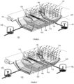
- FIG. 1 A device outside the scope of the invention is shown in figure 1 , which includes at least two filters in parallel.
- the configuration of the device thus represented does not allow denitrification, but only nitrification.
- the water treatment device 10 more specifically comprises a first stage 11, each of the filters 12, 13 of which can be fed by tank using a supply 14 of raw waste water.
- the surface of the first stage 11, planted with reeds, retains/filters the suspended matter contributing to the formation of the sludge layer and whose mechanical action of the plants allows permeability.
- the first stage also comprises, under the reeds, a particulate filter material. Directly under the particulate filter material of the first stage extends the particulate filter material of the second stage 15.
- the second stage 15 is saturated with water: a loading inspection chamber 16 makes it possible to maintain the water level.
- a forced aeration system 17 allows oxygen to be injected into the treatment device 10. More specifically, the forced aeration system comprises a booster 18 and a network of pipes 19 extending into the bottom 20 of the water treatment device 10.
- the network of pipes 19 extends against the geomembrane covering the surface of the ground in which the device is installed.
- the network of pipes 19 is for example made up of a plurality of perforated pipes, to allow the air supplied by the booster 18 to be released.
- the pipes are for example spaced 5 to 20 cm from each other to ensure good distribution of the oxygen over the entire surface of the device.
- a drain 21 also extends into the bottom 20 of the device 10 to recover the treated water and drain it to the outside of the device.
- the screened wastewater arriving at one of the filters 12, 13 of the first stage 11 percolates vertically in said filter 12.
- the mineralization of the sludge accumulating on the surface of the first filter 12 of the first stage 11 is promoted by the good oxygenation of said filter 12.
- the forced aeration system 17 makes it possible to increase the oxygenation of the filter 12 and thus optimizes the mineralization of the sludge.
- the second filter 13 since the second filter 13 is at rest, the sludge that may have accumulated on the surface of the second filter 13 during a previous feeding phase can continue to mineralize and any clogging is thus avoided.
- the waters percolate vertically in a first filter 22 of the second stage 15, located under the first filter 12 of the first stage 11.
- the biological degradation which began in the filter 12 of the first stage 11 continues in the filter 22 of the second stage 15, including nitrification, promoted by the significant oxygenation of said filter by means of the forced aeration system 17.
- the treated water is discharged via the drain 21 extending over the bottom of the device 10, along the filters 22 and 23 of the second stage 15.
- a slope may be provided at the bottom 20 of the device 10, on either side of the drain 21, in order to avoid stagnation zones.
- THE figures 2 , 3 and 4 represent an exemplary embodiment of the device according to the invention, which also comprises two series of filters in parallel.
- the water treatment device 100 also comprises a first stage 101, each of the filters 102, 103 of which can be fed by tank by means of a supply 104 of de-screened raw wastewater.
- a second stage 105, saturated with water, is directly located under the first stage 101.
- a forced aeration system 110 capable of operating alternately, makes it possible to inject oxygen into the treatment device 100, from one and/or the other of the two filters 106, 107 of the second stage 105.
- a valve system (not shown) makes it possible to supply oxygen alternately to a network of pipes extending under the first filter 106 of the second stage 105 or to a network of pipes extending under the second filter 107 of said second stage 105.
- the loading manholes 108, 109 also allow the treated water to be collected. These collection systems can operate alternately, in order to recover the treated water from one or the other of said systems.
- the device 100 can advantageously be used as described here: A batch of screened raw effluent is poured onto the first filter 102 of the first stage 101 ( figures 2 And 3 ). The waste water percolates vertically towards the first filter 106 of the second stage 105. Here again, the mineralization of the sludge accumulating on the surface of the first filter 102 is promoted by the good oxygenation of said filter 102.
- the second filter 103 of the first stage 101 is, for its part, at rest.
- the forced aeration system 110 advantageously injects oxygen only at the level of the first filter 106 of the first stage.
- said first filter 106 is in aerobic conditions, while the second filter 107 is in anoxic conditions.
- the waters percolate vertically in the first filter 106 of the second stage 105, located under the first filter 102 of the first stage 101.
- the conditions within the first filter 106 of the second stage 105 are met to allow the treatment of dissolved pollution including nitrification.
- the collection system 109 located opposite the first filter 106 of the second stage 105 is in operation, while the collection system 108 located on the side of said first filter 106 is not operating (valve closed).
- the treated water must pass through the second filter 107 of the second stage 105, in which it will percolate horizontally.
- the second filter 107 being in anoxic conditions, the nitrification of the nitrates can then take place.
- a treatment of the overall nitrogen is obtained.
- the second filter 103 of the first stage 101 which is supplied, the first filter 101 being put to rest.
- the forced aeration system 110 also changes the oxygen injection zone, so that the first filter 106 of the second stage 105 is in anoxic conditions, while the second filter 107 of said second stage 105 is in aerobic conditions.
- the activated collection system is reversed.
- the treated water is evacuated by the system 108 located opposite the second filter 107, so that the water which percolates vertically in the second filter 107 also percolates horizontally in the first filter 106 before being evacuated.
Landscapes
- Life Sciences & Earth Sciences (AREA)
- Biodiversity & Conservation Biology (AREA)
- Microbiology (AREA)
- Hydrology & Water Resources (AREA)
- Engineering & Computer Science (AREA)
- Environmental & Geological Engineering (AREA)
- Water Supply & Treatment (AREA)
- Chemical & Material Sciences (AREA)
- Organic Chemistry (AREA)
- Biological Treatment Of Waste Water (AREA)
- Purification Treatments By Anaerobic Or Anaerobic And Aerobic Bacteria Or Animals (AREA)
- Organic Low-Molecular-Weight Compounds And Preparation Thereof (AREA)
Claims (7)
- Abwasserreinigungsvorrichtung (10, 100) vom Typ Filterkörper, umfassend zwei parallele Filterreihen (12, 22, 13, 23; 102, 106, 103, 107), die alternierend arbeiten, wobei jede Filterreihe umfasst- eine erste Stufe (11, 101) mit immobilisierter, frei entwässerter vertikaler Strömungskultur, bestehend aus wenigstens einem bepflanzten Filter, der geeignet ist, unbehandeltes Abwasser aufzunehmen und auf der Oberfläche des Filters den Schlamm zurückzuhalten, wobei die erste Stufe jeder Filterreihe alternierend von einem Tank versorgt werden kann, so dass bei Zulauf von einem Abwassertank das Wasser sich auf der Oberfläche des versorgten Filters verteilt, dann dort gleichmäßig in Richtung der Unterseite vertikal versickert, während der Schlamm sich auf der Oberfläche des Filters ansammelt,- eine zweite Stufe (15, 105) mit immobilisierter Kultur, die mit vertikal oder horizontal strömenden Wasser gesättigt ist, wobei die erste Stufe direkt über der zweiten Stufe angeordnet ist, so dass das Sickerwasser durch die erste Stufe in die zweite Stufe gelangt, wobei die zweite Stufe Mittel zur Befüllung (16, 108, 109) zur Aufrechterhaltung des Wasserstands umfasst,- ein Zwangsbelüftungssystem (17, 110), das diskontinuierlich arbeiten kann, umfassend ein Verteilungsnetz, das sich unter der zweiten Stufe erstreckt, über die gesamte Oberfläche der Unterseite der Vorrichtung verteilt und geeignet ist, Sauerstoff der ersten und zweiten Stufe zuzuführen, und- eine Drainage zur Rückgewinnung (21) von behandeltem Wasser, die an der Unterseite und an einem Filterende der zweiten Stufe in Abhängigkeit der horizontalen Strömungsrichtung in dem Filter angeordnet ist,wobei die Vorrichtung zwei Sammelsysteme (108, 109) des behandelten Abwassers umfasst, die jeweils auf Niveau der zweiten Stufe einer unterschiedlichen Filterreihe auf beiden Seiten der Vorrichtung verteilt sind und alternierend arbeiten sollen,wobei die Filter der beiden zweiten Stufen aneinandergrenzen und die Vorrichtung derart betrieben werden kann, dass das Wasser senkrecht zu einem der Filter und dann horizontal zu dem benachbarten Filter fließt.
- Abwasserreinigungsvorrichtung gemäß Anspruch 1, wobei die erste Stufe eine Dicke von 10 bis 50 cm und/oder die zweite Stufe eine Dicke von 100 bis 200 cm aufweist.
- Abwasserreinigungsvorrichtung gemäß einem der vorhergehenden Ansprüche, wobei die erste Stufe ein mit Makrophyten bepflanzter Filter, vorzugsweise ein mit Schilf bepflanzter Filter ist.
- Abwasserreinigungsvorrichtung gemäß einem der vorhergehenden Ansprüche, wobei das Zwangsbelüftungssystem alternierend und/oder sequenziell an dem einen oder anderen Filter (106, 107) der zweiten Stufe betrieben werden kann, um auf diese Weise aerobe und anoxische Bedingungen in den Filtern abwechselnd herzustellen.
- Verfahren zur Abwasserbehandlung oder zur Mineralisierung von Schlamm, das die Abwasserreinigungsvorrichtung gemäß einem der Ansprüche 1 bis 4 verwendet, in dem abwechselnd die erste Stufe einer ersten Filterreihe mit unbehandeltem Abwasser oder Schlamm versorgt wird, wobei die erste Stufe einer zweiten Filterreihe mit unbehandeltem Abwasser oder Schlamm nicht versorgt wird, und umgekehrt, und in dem das Zwangsbelüftungssystem alternativ oder sequenziell arbeitet, so dass, wenn die zweite Stufe der mit unbehandeltem Abwasser oder Schlamm versorgten Filterreihe mit Sauerstoff versorgt wird, die zweite Stufe der mit unbehandeltem Abwasser oder Schlamm nicht versorgten Filterreihe nicht mit Sauerstoff versorgt wird, um anoxische Bedingungen zu schaffen, und behandeltes Abwasser mit den Sammelsystemen alternierend gesammelt wird, wobei das Verfahren umfassteine Phase (A) der Mineralisation von Schlamm, der sich an der Oberfläche der ersten Stufe der Filterreihe ansammelt, die mit unbehandeltem Abwasser oder Schlamm versorgt wird,eine Phase (B) der Nitrifikation und des aeroben Abbaus der gelösten Schadstoffe auf Niveau der zweiten Stufe der Filterreihe, die mit unbehandeltem Abwasser oder Schlamm versorgt wird und mit Sauerstoff mithilfe des Zwangsbelüftungssystems versorgt wird;eine Phase (C) der Ableitung des behandelten Wassers,wobei das Verfahren, vor der Phase (C) der Ableitung, eine Phase (D) der Denitrifikation auf Niveau des Filters der zweiten Stufe unter anoxischen Bedingungen umfasst, undwobei die Phase (C) der Ableitung in einer Weise erfolgt, dass das Abwasser vertikal in die zweite Stufe der Filterreihe, die mit unbehandeltem Abwasser oder Schlamm versorgt wird, von der ersten Stufe aus, die mit unbehandeltem Abwasser oder mit Schlamm versorgt wird, dann horizontal in die zweite Stufe der nicht versorgten Filterreihe sickert, bevor es über die Rückgewinnungsdrainage zurückgewonnen wird und dann mithilfe des Sammelsystems der nicht versorgten Filterreihe abgeleitet wird.
- Verfahren zur Abwasserbehandlung gemäß Anspruch 5, wobei die Phase (B) des aeroben Abbaus der gelösten Schadstoffe auf Niveau der gesättigten und belüfteten zweiten Stufe wenigstens von einer partiellen Eliminierung von pathogenen Keimen begleitet ist, die im Abwasser vorhanden sind.
- Verfahren zur Abwasserbehandlung gemäß einem der Ansprüche 5 oder 6, wobei die Filter abwechselnd arbeiten, um Phasen der aktiven Belüftung und Ruhephasen zyklisch abzuwechseln.
Applications Claiming Priority (2)
| Application Number | Priority Date | Filing Date | Title |
|---|---|---|---|
| FR1553702A FR3035395B1 (fr) | 2015-04-24 | 2015-04-24 | Dispositif d'epuration d'eaux usees et utilisations |
| PCT/FR2016/050945 WO2016170279A1 (fr) | 2015-04-24 | 2016-04-22 | Dispositif d'épuration d'eaux usées et procédé de traitement d'eau |
Publications (3)
| Publication Number | Publication Date |
|---|---|
| EP3286147A1 EP3286147A1 (de) | 2018-02-28 |
| EP3286147C0 EP3286147C0 (de) | 2024-11-06 |
| EP3286147B1 true EP3286147B1 (de) | 2024-11-06 |
Family
ID=53524820
Family Applications (1)
| Application Number | Title | Priority Date | Filing Date |
|---|---|---|---|
| EP16723429.3A Active EP3286147B1 (de) | 2015-04-24 | 2016-04-22 | Abwasserreinigungsvorrichtung und wasseraufbereitungsprozess |
Country Status (9)
| Country | Link |
|---|---|
| US (1) | US10526222B2 (de) |
| EP (1) | EP3286147B1 (de) |
| CA (1) | CA2987818A1 (de) |
| CO (1) | CO2017011807A2 (de) |
| ES (1) | ES3008573T3 (de) |
| FR (1) | FR3035395B1 (de) |
| MX (2) | MX2020002277A (de) |
| PL (1) | PL3286147T3 (de) |
| WO (1) | WO2016170279A1 (de) |
Families Citing this family (2)
| Publication number | Priority date | Publication date | Assignee | Title |
|---|---|---|---|---|
| CA2940367C (en) * | 2016-08-29 | 2021-11-16 | Clayton Quinn | Apparatus includes elastically deformable member having terminal assemblies |
| EP3578523B1 (de) * | 2018-06-04 | 2023-09-13 | BAUER Resources GmbH | Transportable kläreinheit sowie verfahren zum klären von abwasser |
Citations (6)
| Publication number | Priority date | Publication date | Assignee | Title |
|---|---|---|---|---|
| US6126827A (en) * | 1993-11-30 | 2000-10-03 | Charles L. Johnson, Jr. | High-strength septage biological treatment system |
| US6652743B2 (en) * | 1997-06-23 | 2003-11-25 | North American Wetland Engineering, Inc. | System and method for removing pollutants from water |
| DE20221682U1 (de) * | 1970-02-14 | 2007-02-22 | Bednarsch, Marcus | Pflanzenkläranlage |
| EP2213629A1 (de) * | 2009-01-30 | 2010-08-04 | BAUER Umwelt GmbH | Anlage und Verfahren zur Aufbereitung und Entsorgung von salz- und ölhaltigem Abwasser |
| FR2973796A1 (fr) * | 2011-04-06 | 2012-10-12 | Voisin J | Dispositif de traitement des eaux usees |
| WO2016110657A1 (fr) * | 2015-01-09 | 2016-07-14 | J Voisin | Dispositif de traitement des eaux usées, de type filtre planté à percolation verticale, comprenant un système d'aération actif d'une couche inférieure saturée |
Family Cites Families (6)
| Publication number | Priority date | Publication date | Assignee | Title |
|---|---|---|---|---|
| DE4119835A1 (de) * | 1991-06-12 | 1992-12-17 | Schneider Horst Dr Ing | Verfahren zur biologischen abwasserreinigung in einem mit sumpfpflanzen besetzten becken |
| US6200469B1 (en) * | 1997-06-23 | 2001-03-13 | North American Wetland Engineering | System for removing pollutants from water |
| FR2833254B1 (fr) * | 2001-12-07 | 2004-10-08 | Rhizos Engenierie | Procede d'epuration biologique des eaux, module et unite de traitement destinee a l'epuration de l'eau |
| WO2006030164A1 (fr) * | 2004-09-16 | 2006-03-23 | Phytorestore | Traitement de polluants par phytolixiviation |
| FR2913418B1 (fr) * | 2007-03-09 | 2009-06-12 | Assainisud Sarl | Module d'epuration pour effluents et station d'epuration equipee d'un tel module |
| ES2370878B1 (es) * | 2011-07-05 | 2013-02-11 | Gestión Depuración Y Servicios Sl | Procedimiento para la depuración de aguas residuales mediante equipos ecológicos y compactos. |
-
2015
- 2015-04-24 FR FR1553702A patent/FR3035395B1/fr active Active
-
2016
- 2016-04-22 US US15/568,880 patent/US10526222B2/en not_active Expired - Fee Related
- 2016-04-22 EP EP16723429.3A patent/EP3286147B1/de active Active
- 2016-04-22 ES ES16723429T patent/ES3008573T3/es active Active
- 2016-04-22 MX MX2020002277A patent/MX2020002277A/es unknown
- 2016-04-22 WO PCT/FR2016/050945 patent/WO2016170279A1/fr not_active Ceased
- 2016-04-22 PL PL16723429.3T patent/PL3286147T3/pl unknown
- 2016-04-22 CA CA2987818A patent/CA2987818A1/en not_active Abandoned
- 2016-04-22 MX MX2017013612A patent/MX2017013612A/es active IP Right Grant
-
2017
- 2017-11-21 CO CONC2017/0011807A patent/CO2017011807A2/es unknown
Patent Citations (6)
| Publication number | Priority date | Publication date | Assignee | Title |
|---|---|---|---|---|
| DE20221682U1 (de) * | 1970-02-14 | 2007-02-22 | Bednarsch, Marcus | Pflanzenkläranlage |
| US6126827A (en) * | 1993-11-30 | 2000-10-03 | Charles L. Johnson, Jr. | High-strength septage biological treatment system |
| US6652743B2 (en) * | 1997-06-23 | 2003-11-25 | North American Wetland Engineering, Inc. | System and method for removing pollutants from water |
| EP2213629A1 (de) * | 2009-01-30 | 2010-08-04 | BAUER Umwelt GmbH | Anlage und Verfahren zur Aufbereitung und Entsorgung von salz- und ölhaltigem Abwasser |
| FR2973796A1 (fr) * | 2011-04-06 | 2012-10-12 | Voisin J | Dispositif de traitement des eaux usees |
| WO2016110657A1 (fr) * | 2015-01-09 | 2016-07-14 | J Voisin | Dispositif de traitement des eaux usées, de type filtre planté à percolation verticale, comprenant un système d'aération actif d'une couche inférieure saturée |
Also Published As
| Publication number | Publication date |
|---|---|
| CA2987818A1 (en) | 2016-10-27 |
| ES3008573T3 (en) | 2025-03-24 |
| EP3286147C0 (de) | 2024-11-06 |
| US10526222B2 (en) | 2020-01-07 |
| FR3035395B1 (fr) | 2021-09-24 |
| PL3286147T3 (pl) | 2025-07-14 |
| MX2020002277A (es) | 2020-07-13 |
| US20180105445A1 (en) | 2018-04-19 |
| WO2016170279A1 (fr) | 2016-10-27 |
| MX2017013612A (es) | 2018-08-28 |
| FR3035395A1 (fr) | 2016-10-28 |
| CO2017011807A2 (es) | 2018-02-09 |
| EP3286147A1 (de) | 2018-02-28 |
Similar Documents
| Publication | Publication Date | Title |
|---|---|---|
| EP1791793B1 (de) | Verfahren zur behandlung von schadstoffen durch pflanzenauslaugung | |
| EP3242859B1 (de) | Abwasserbehandlungsvorrichtung wie z. b. ein bepflanzter filter mit vertikaler perkolation mit einem system zur aktiven belüftung einer gesättigten unteren schicht | |
| EP1857419B1 (de) | Verfahren und Anlage zur Abwasseraufbereitung | |
| FR2954762A1 (fr) | Filtre organique plante avec cannes europeennes et/ou tropicales/desertiques pour le traitement d'eaux, de sols ou d'air pollues | |
| FR2942791A1 (fr) | Dispositif d'assainissement compact par filtre plante, notamment du type plante de roseaux | |
| EP3286147B1 (de) | Abwasserreinigungsvorrichtung und wasseraufbereitungsprozess | |
| DeBusk et al. | The use of macrophyte-based systems for phosphorus removal: an overview of 25 years of research and operational results in Florida | |
| FR2690683A1 (fr) | Procédé et installation d'épuration d'eaux résiduaires, et en particulier d'élimination de la pollution azotée, par voie biologique. | |
| EP1492733B1 (de) | Ausgerüstete pflanzungen zu behandlung von organischen abwässern durch biologische sanierung | |
| WO2021251811A1 (fr) | Dispositif de traitement des eaux usees par filtres vetiver zizania et biochar | |
| FR2973796A1 (fr) | Dispositif de traitement des eaux usees | |
| WO2021018629A1 (fr) | Ouvrage d'assainissement des eaux usées | |
| WO2015107174A1 (fr) | Dispositif de traitement d'eaux usées | |
| EP1674430B1 (de) | Vorrichtung zur Behandlung von Abwasser und Verfahren das sie verwendet | |
| FR2889518A1 (fr) | Systeme pour le traitement des eaux usees domestiques | |
| EP3214049B1 (de) | Vorrichtung zur behandlung von abwasser mit einem mikrobiologischen bett | |
| FR2799457A1 (fr) | Filtre, plante de roseaux, epurateur d'effluents domestiques , industriels, compose de 2 bassins aeres, fonctionnant, en alternance par percolation d'effluent brut sur 1m2/habitant | |
| EP1598320B1 (de) | Biologischer Filter zur Abwasserbehandlung | |
| FR3146674A1 (fr) | Dispositif de traitement des eaux usées par filtre planté équipé d’un dispositif d’injection de bactéries dans un ouvrage de prétraitement de type chasse ou poste | |
| BE1013375A3 (fr) | Procede et installation pour la nitrification d'eaux polluees. ' | |
| Ruiz | Optimization of French Vertical Flow Treatment Wetlands applied to domestic wastewater treatment for different levels of performances | |
| FR3077071A1 (fr) | Dispositif de traitement des eaux usees | |
| FR3129389A1 (fr) | Dispositif de traitement des eaux usées par filtre planté équipé d’un ouvrage de type chasse ou poste | |
| FR3076829A1 (fr) | Dispositif et procede de traitement d'eaux usees, integrant un bassin de purification de type filtre plante et un reacteur biologique | |
| EP1674429A1 (de) | Vorrichtung zur Behandlung von Abwasser und ihre Verwendung |
Legal Events
| Date | Code | Title | Description |
|---|---|---|---|
| STAA | Information on the status of an ep patent application or granted ep patent |
Free format text: STATUS: THE INTERNATIONAL PUBLICATION HAS BEEN MADE |
|
| PUAI | Public reference made under article 153(3) epc to a published international application that has entered the european phase |
Free format text: ORIGINAL CODE: 0009012 |
|
| STAA | Information on the status of an ep patent application or granted ep patent |
Free format text: STATUS: REQUEST FOR EXAMINATION WAS MADE |
|
| 17P | Request for examination filed |
Effective date: 20171120 |
|
| AK | Designated contracting states |
Kind code of ref document: A1 Designated state(s): AL AT BE BG CH CY CZ DE DK EE ES FI FR GB GR HR HU IE IS IT LI LT LU LV MC MK MT NL NO PL PT RO RS SE SI SK SM TR |
|
| AX | Request for extension of the european patent |
Extension state: BA ME |
|
| DAV | Request for validation of the european patent (deleted) | ||
| DAX | Request for extension of the european patent (deleted) | ||
| TPAC | Observations filed by third parties |
Free format text: ORIGINAL CODE: EPIDOSNTIPA |
|
| STAA | Information on the status of an ep patent application or granted ep patent |
Free format text: STATUS: EXAMINATION IS IN PROGRESS |
|
| 17Q | First examination report despatched |
Effective date: 20200127 |
|
| TPAC | Observations filed by third parties |
Free format text: ORIGINAL CODE: EPIDOSNTIPA |
|
| GRAP | Despatch of communication of intention to grant a patent |
Free format text: ORIGINAL CODE: EPIDOSNIGR1 |
|
| STAA | Information on the status of an ep patent application or granted ep patent |
Free format text: STATUS: GRANT OF PATENT IS INTENDED |
|
| INTG | Intention to grant announced |
Effective date: 20240325 |
|
| GRAS | Grant fee paid |
Free format text: ORIGINAL CODE: EPIDOSNIGR3 |
|
| GRAA | (expected) grant |
Free format text: ORIGINAL CODE: 0009210 |
|
| STAA | Information on the status of an ep patent application or granted ep patent |
Free format text: STATUS: THE PATENT HAS BEEN GRANTED |
|
| AK | Designated contracting states |
Kind code of ref document: B1 Designated state(s): AL AT BE BG CH CY CZ DE DK EE ES FI FR GB GR HR HU IE IS IT LI LT LU LV MC MK MT NL NO PL PT RO RS SE SI SK SM TR |
|
| RAP1 | Party data changed (applicant data changed or rights of an application transferred) |
Owner name: RIETLAND BVBA Owner name: NATURALLY WALLACE CONSULTING LLC Owner name: SAVEA |
|
| REG | Reference to a national code |
Ref country code: GB Ref legal event code: FG4D Free format text: NOT ENGLISH |
|
| REG | Reference to a national code |
Ref country code: CH Ref legal event code: EP |
|
| REG | Reference to a national code |
Ref country code: DE Ref legal event code: R096 Ref document number: 602016090121 Country of ref document: DE |
|
| REG | Reference to a national code |
Ref country code: IE Ref legal event code: FG4D Free format text: LANGUAGE OF EP DOCUMENT: FRENCH |
|
| U01 | Request for unitary effect filed |
Effective date: 20241202 |
|
| U07 | Unitary effect registered |
Designated state(s): AT BE BG DE DK EE FI FR IT LT LU LV MT NL PT RO SE SI Effective date: 20241211 |
|
| REG | Reference to a national code |
Ref country code: ES Ref legal event code: FG2A Ref document number: 3008573 Country of ref document: ES Kind code of ref document: T3 Effective date: 20250324 |
|
| PG25 | Lapsed in a contracting state [announced via postgrant information from national office to epo] |
Ref country code: HR Free format text: LAPSE BECAUSE OF FAILURE TO SUBMIT A TRANSLATION OF THE DESCRIPTION OR TO PAY THE FEE WITHIN THE PRESCRIBED TIME-LIMIT Effective date: 20241106 Ref country code: IS Free format text: LAPSE BECAUSE OF FAILURE TO SUBMIT A TRANSLATION OF THE DESCRIPTION OR TO PAY THE FEE WITHIN THE PRESCRIBED TIME-LIMIT Effective date: 20250306 |
|
| PG25 | Lapsed in a contracting state [announced via postgrant information from national office to epo] |
Ref country code: NO Free format text: LAPSE BECAUSE OF FAILURE TO SUBMIT A TRANSLATION OF THE DESCRIPTION OR TO PAY THE FEE WITHIN THE PRESCRIBED TIME-LIMIT Effective date: 20250206 |
|
| PG25 | Lapsed in a contracting state [announced via postgrant information from national office to epo] |
Ref country code: GR Free format text: LAPSE BECAUSE OF FAILURE TO SUBMIT A TRANSLATION OF THE DESCRIPTION OR TO PAY THE FEE WITHIN THE PRESCRIBED TIME-LIMIT Effective date: 20250207 |
|
| PG25 | Lapsed in a contracting state [announced via postgrant information from national office to epo] |
Ref country code: RS Free format text: LAPSE BECAUSE OF FAILURE TO SUBMIT A TRANSLATION OF THE DESCRIPTION OR TO PAY THE FEE WITHIN THE PRESCRIBED TIME-LIMIT Effective date: 20250206 |
|
| U20 | Renewal fee for the european patent with unitary effect paid |
Year of fee payment: 10 Effective date: 20250414 |
|
| PG25 | Lapsed in a contracting state [announced via postgrant information from national office to epo] |
Ref country code: SM Free format text: LAPSE BECAUSE OF FAILURE TO SUBMIT A TRANSLATION OF THE DESCRIPTION OR TO PAY THE FEE WITHIN THE PRESCRIBED TIME-LIMIT Effective date: 20241106 |
|
| PGFP | Annual fee paid to national office [announced via postgrant information from national office to epo] |
Ref country code: PL Payment date: 20250416 Year of fee payment: 10 |
|
| PGFP | Annual fee paid to national office [announced via postgrant information from national office to epo] |
Ref country code: ES Payment date: 20250513 Year of fee payment: 10 |
|
| PG25 | Lapsed in a contracting state [announced via postgrant information from national office to epo] |
Ref country code: SK Free format text: LAPSE BECAUSE OF FAILURE TO SUBMIT A TRANSLATION OF THE DESCRIPTION OR TO PAY THE FEE WITHIN THE PRESCRIBED TIME-LIMIT Effective date: 20241106 |
|
| PG25 | Lapsed in a contracting state [announced via postgrant information from national office to epo] |
Ref country code: CZ Free format text: LAPSE BECAUSE OF FAILURE TO SUBMIT A TRANSLATION OF THE DESCRIPTION OR TO PAY THE FEE WITHIN THE PRESCRIBED TIME-LIMIT Effective date: 20241106 |
|
| PGFP | Annual fee paid to national office [announced via postgrant information from national office to epo] |
Ref country code: IE Payment date: 20250415 Year of fee payment: 10 |
|
| PLBE | No opposition filed within time limit |
Free format text: ORIGINAL CODE: 0009261 |
|
| STAA | Information on the status of an ep patent application or granted ep patent |
Free format text: STATUS: NO OPPOSITION FILED WITHIN TIME LIMIT |
|
| 26N | No opposition filed |
Effective date: 20250807 |
|
| REG | Reference to a national code |
Ref country code: CH Ref legal event code: H13 Free format text: ST27 STATUS EVENT CODE: U-0-0-H10-H13 (AS PROVIDED BY THE NATIONAL OFFICE) Effective date: 20251125 |
|
| PG25 | Lapsed in a contracting state [announced via postgrant information from national office to epo] |
Ref country code: MC Free format text: LAPSE BECAUSE OF FAILURE TO SUBMIT A TRANSLATION OF THE DESCRIPTION OR TO PAY THE FEE WITHIN THE PRESCRIBED TIME-LIMIT Effective date: 20241106 |
|
| PG25 | Lapsed in a contracting state [announced via postgrant information from national office to epo] |
Ref country code: CH Free format text: LAPSE BECAUSE OF NON-PAYMENT OF DUE FEES Effective date: 20250430 |
|
| PGFP | Annual fee paid to national office [announced via postgrant information from national office to epo] |
Ref country code: GB Payment date: 20260330 Year of fee payment: 11 |