EP1598294A2 - Bogenbearbeitungseinrichtung - Google Patents
Bogenbearbeitungseinrichtung Download PDFInfo
- Publication number
- EP1598294A2 EP1598294A2 EP05008405A EP05008405A EP1598294A2 EP 1598294 A2 EP1598294 A2 EP 1598294A2 EP 05008405 A EP05008405 A EP 05008405A EP 05008405 A EP05008405 A EP 05008405A EP 1598294 A2 EP1598294 A2 EP 1598294A2
- Authority
- EP
- European Patent Office
- Prior art keywords
- roller
- processing apparatus
- conveying
- dust
- sheet processing
- Prior art date
- Legal status (The legal status is an assumption and is not a legal conclusion. Google has not performed a legal analysis and makes no representation as to the accuracy of the status listed.)
- Withdrawn
Links
- 238000004140 cleaning Methods 0.000 claims abstract description 41
- 229920001971 elastomer Polymers 0.000 claims abstract description 14
- 239000005060 rubber Substances 0.000 claims abstract description 14
- 239000000428 dust Substances 0.000 claims description 50
- 239000000463 material Substances 0.000 claims description 5
- 238000007790 scraping Methods 0.000 claims description 4
- 239000011148 porous material Substances 0.000 claims description 3
- 238000000926 separation method Methods 0.000 claims description 3
- 238000000034 method Methods 0.000 claims description 2
- 238000002474 experimental method Methods 0.000 description 7
- 238000007689 inspection Methods 0.000 description 7
- 238000010586 diagram Methods 0.000 description 6
- 239000004744 fabric Substances 0.000 description 5
- 229920003043 Cellulose fiber Polymers 0.000 description 3
- 229920000742 Cotton Polymers 0.000 description 3
- 238000010276 construction Methods 0.000 description 3
- 230000002093 peripheral effect Effects 0.000 description 3
- 238000007789 sealing Methods 0.000 description 3
- 239000004677 Nylon Substances 0.000 description 2
- 238000001514 detection method Methods 0.000 description 2
- 229920001778 nylon Polymers 0.000 description 2
- 229920000297 Rayon Polymers 0.000 description 1
- 230000005489 elastic deformation Effects 0.000 description 1
- 238000012423 maintenance Methods 0.000 description 1
- 230000003287 optical effect Effects 0.000 description 1
- 230000000737 periodic effect Effects 0.000 description 1
- 239000002964 rayon Substances 0.000 description 1
- 239000007779 soft material Substances 0.000 description 1
Images


Classifications
-
- B—PERFORMING OPERATIONS; TRANSPORTING
- B65—CONVEYING; PACKING; STORING; HANDLING THIN OR FILAMENTARY MATERIAL
- B65H—HANDLING THIN OR FILAMENTARY MATERIAL, e.g. SHEETS, WEBS, CABLES
- B65H3/00—Separating articles from piles
- B65H3/02—Separating articles from piles using friction forces between articles and separator
- B65H3/06—Rollers or like rotary separators
-
- B—PERFORMING OPERATIONS; TRANSPORTING
- B65—CONVEYING; PACKING; STORING; HANDLING THIN OR FILAMENTARY MATERIAL
- B65H—HANDLING THIN OR FILAMENTARY MATERIAL, e.g. SHEETS, WEBS, CABLES
- B65H3/00—Separating articles from piles
- B65H3/46—Supplementary devices or measures to assist separation or prevent double feed
- B65H3/52—Friction retainers acting on under or rear side of article being separated
- B65H3/5246—Driven retainers, i.e. the motion thereof being provided by a dedicated drive
-
- B—PERFORMING OPERATIONS; TRANSPORTING
- B65—CONVEYING; PACKING; STORING; HANDLING THIN OR FILAMENTARY MATERIAL
- B65H—HANDLING THIN OR FILAMENTARY MATERIAL, e.g. SHEETS, WEBS, CABLES
- B65H3/00—Separating articles from piles
-
- B—PERFORMING OPERATIONS; TRANSPORTING
- B65—CONVEYING; PACKING; STORING; HANDLING THIN OR FILAMENTARY MATERIAL
- B65H—HANDLING THIN OR FILAMENTARY MATERIAL, e.g. SHEETS, WEBS, CABLES
- B65H3/00—Separating articles from piles
- B65H3/02—Separating articles from piles using friction forces between articles and separator
- B65H3/06—Rollers or like rotary separators
- B65H3/0653—Rollers or like rotary separators for separating substantially vertically stacked articles
-
- B—PERFORMING OPERATIONS; TRANSPORTING
- B65—CONVEYING; PACKING; STORING; HANDLING THIN OR FILAMENTARY MATERIAL
- B65H—HANDLING THIN OR FILAMENTARY MATERIAL, e.g. SHEETS, WEBS, CABLES
- B65H2301/00—Handling processes for sheets or webs
- B65H2301/50—Auxiliary process performed during handling process
- B65H2301/53—Auxiliary process performed during handling process for acting on performance of handling machine
- B65H2301/531—Cleaning parts of handling machine
-
- B—PERFORMING OPERATIONS; TRANSPORTING
- B65—CONVEYING; PACKING; STORING; HANDLING THIN OR FILAMENTARY MATERIAL
- B65H—HANDLING THIN OR FILAMENTARY MATERIAL, e.g. SHEETS, WEBS, CABLES
- B65H2701/00—Handled material; Storage means
- B65H2701/10—Handled articles or webs
- B65H2701/19—Specific article or web
- B65H2701/1916—Envelopes and articles of mail
Definitions
- This invention relates to a sheet processing apparatus that is provided with a cleaning roller to remove paper-dust adhered to members to contact sheets in a sheet processing apparatus such as, for example, a postal matter processing apparatus, a banknote processing apparatus and the like.
- a sheet processing apparatus such as a postal matter processing apparatus, a banknote processing apparatus, etc. is provided with devices to take out sheets one by one from a bundled state in a take-out portion as disclosed in the Japanese Patent Application Publication No. 2003-81461.
- Such take-out devices are broadly divided into a friction type using a rubber roller and a suction type using a suction drum.
- a friction type take-out device using a rubber roller more than two sheets may be taken out and are supplied into a sheet processing apparatus after separated into a single sheet.
- the frictional force of the rubber roller surface largely affects the sheet processing capacity and it is therefore important to keep a frictional coefficient of the rubber roller surface always stable.
- An object of this invention is to provide a sheet processing apparatus that is capable of efficiently cleaning paper-dust adhered to such sheet conveying means as a take-out roller, a feed roller, a conveying roller, a conveying belt, etc.
- a sheet processing apparatus comprising conveying means for conveying sheets in contact with them; processing means for performing a specified process of the sheets conveyed by the conveying means; and a cleaning roller of which surface is formed of a porous material to remove paper-dust from the surface of the conveying means by rotating in contact with the conveying means.
- FIG. 1 is a top view of the rough construction of a postal matter processing apparatus showing a face culler canceller (a post-office stamp)that is a part of the postal matter processing apparatus in an embodiment of this invention;
- FIG. 2 is a rough construction diagram showing the vicinity of a take-out portion of the face culler canceller (the post-office stamp) shown in FIG. 1;
- FIG. 3 is a top view showing the state where one sheet of postal matter fed between a feed roller and a reversing roller;
- FIG. 4 is a top view showing the state where two sheets of postal matter are fed between the feed roller and the reversing roller;
- FIG. 5 is a conceptual diagram of the experiments conducted for the paper-dust collecting capacity of a sheet of paper and a roller shaped member
- FIG. 6 is a graph showing the results of the experiments conducted for the materials or roller and paper-dust gatherring capacity
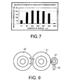
- FIG. 7 is a graph showing the relationship between diameter of vesicle of sponge and weight of paper-dust gatherring amount
- FIG. 8 is a conceptual diagram showing a usage pattern of a feed roller, a reversing roller and a cleaning roller.
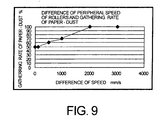
- FIG. 9 is a graph showing the results of the experiments conducted for the relative rotational speed of the feed roller and the reversing roller (a peripheral speed difference of rollers) and a gathering rate of paper-dust.
- FIG. 1 is a top view showing the rough construction of a face culler canceller 1 of a sheet processing apparatus involved in the embodiment of this invention, which cancels postal indicias such as stamps pasted on postal matters P, sorts and stacks them.
- Face culler canceller 1 is composed of an insert port 2, a take-out portion 4, an inspection portion 5, a rejection stacker 6, detectors 7a and 7b, a reversing portion 8, a sealing portion 9, and a sorting stacker 10.
- Postal matters P sheets
- Inspection portion 5 inspects postal matters P taken out on conveying route 3 for postal matters containing foreign matters and irregular-size postal matters.
- Inspection portions 7a and 7b detect postal indicias pasted on the surfaces of postal matters P passed through inspection portion 5 and judged to be normal postal matters that can be processed.
- reversing portion 8 postal matters P are turned over upside down selectively based on the detection result in inspection portions 7a and 7b.
- sealing portion 9 postal indicias pasted on postal matters P passed through reversing portion 8 are stamped as necessary.
- Sorting stacker 10 is composed of sorting boxes 10a to 10f and postal matters P are sorted and stacked in sorting boxes 10a to 10f according to the detection results by detectors 7a and 7b. Detectors 7a and 7b, reversing portion 8 and sealing portion 9 partially comprise the processing means to make the face culler cancellation.
- Face culler canceller 1 displays various operational guides to operator and an operation panel 11 to accept various operating inputs made by operator is provided near insert portion 2.
- insert portion 2 plural postal matters P are housed in the state of upright position with the long side in contact with the base. Postal matters P inserted through insert portion 2 are inserted in the loose upside-down and front/back state. Insert portion 2 has a backup plate 2a to press all housed postal matters P toward take-out portion 4 along their stacking direction.
- Take-out portion 4 takes out postal matters inserted into insert portion 2 from the most remote end at the opposite side of pickup plate 2a on conveying route 3 one by one.
- supplied postal matters P are pressed to a take-out roller 20 side by backup plate 2a (not shown in FIG. 2) and a postal matter P at the most remote side is supplied to a feed roller 21 side by take-out roller 20.
- a reversing roller (a separation roller) 22 that will be described later is provided facing to feed roller 21.
- Conveying roller pairs 23 and 24 are provided at the inner side from feed roller 21 in the apparatus to convey postal matters P to inspection portion 5.
- a cleaning roller 27 that is described later is provided to rotate in contact with take-out roller 20, feed roller 21 and conveying rollers 23, 24.
- FIG. 4 is a diagram showing a case wherein two postal matters are taken out by take-out roller 20. In this case, reversing roller 22 rotates in the reverse direction and pushes back a second postal matter P2. After a sensor (not illustrated) detects that a first postal matter P1 passed completely, second postal matter P2 is sent to feed roller 21.
- FIG. 5 is a conceptual diagram showing the experiment made for a paper-dust gatherring capacity of a sheet of paper 50 using a roller-shape member. After sliding a roller 51 rotating at a constant speed with a constant load applied on sheet of paper 50 moving at a constant speed, weights of paper-dust on the surface of roller 51 were measured. Paper-dust weights were measured on roller 51 using various rubber sponges, rubbers, nylon sponges, nylon brushes, leathers and nonwoven clothes, respectively. Materials in hardness within the ranges of HA20 to HA90 (JIS K 6253 Type A) were evaluated. As seen from FIG. 6 showing the results of experiments, paper-dust collection capacity is excellent in rubber sponge, nonwoven cotton cloth and nonwoven rayon cloth and it was revealed that soft materials have especially high paper-dust collecting capacity.
- FIG. 8 is a conceptual diagram showing the using pattern of feed roller 21, reversing roller 22 and cleaning roller 27 described above.
- feed roller 21 and reversing roller 22 are kept in contact with each other except a time when a postal matter P passes. Paper-dust falling from postal matter P is adhered to the surfaces of both rollers of feed roller 21 and reversing roller 22.
- FIG. 9 shows the results of experiment to examine to which roller of feed roller 21 and reversing roller 22 in contact with each other paper-dust adhered on their surfaces moved when a relative rotational speeds of both rollers (a difference in roller peripheral speeds) were optionally changed. It was cleared that when a relative speed difference becomes large, paper-dust was concentrated on the roller at a high-speed rotating side but weights of paper-dust adhered on both rollers tend to be divided equally.
- paper-dust is adhered much to reversing roller 22 side that is mainly sliding together with postal matter P immediately after postal matter P passed.
- paper-dust is divided on both rollers almost equally 2, 3 seconds later.
- Cleaning roller 27 is in contact with feed roller 21 and driven to turn at a higher speed than feed roller 21. Accordingly, paper-dust adhered to feed roller 1 is collected to cleaning roller 27 and paper-dust attached to reversing roller 22 is also collected to cleaning roller 27 through feed roller 21 and cleaned simultaneously.
- cleaning roller 27 is covered by paper-dust in several hours.
- Cellulose fibers are captured mechanically in sponge vesicles of cleaning roller 27 and therefore, paper-dust will not drop from cleaning roller 27 when two rollers are rotating jointly.
- Feed roller 21 and reversing roller 22 are cleaned with the driving of the apparatus and a paper-dust layer is formed on the surface of cleaning roller 27.
- This paper-dust layer becomes a nonwoven cotton (cellulose fiber) cloth roller in a manner. Because of this, as can be presumed from a graph shown in FIG.
- a nonwoven cotton cloth is high in paper-dust gatherring performance and even when a paper-dust layer is formed on the surface of cleaning roller 27, its paper-dust gatherring performance does not drop. Further, the increased diameter of cleaning roller 27 by paper-dust is absorbed by the elastic deformation of sponge.
- the diameter of cleaning roller 27 is increased gradually by a paper-dust layer.
- a scraping plate 28 is provided at a position separated by a fixed space from cleaning roller 27 as shown in FIG. 8.
- paper-dust adhered to cleaning roller 27 is scraped off by scraping plate 28 when cleaning roller 27 is rotated.
- the paper-dust layer can be peeled off easily with a tooth brush or other cleaning jigs, and a frictional coefficients of feed roller 21 and reversing roller 22 can be maintained for an extended period without dropping the take-out efficiency when cleaning roller 27 is cleaned in a periodic maintenance work.
- Cleaning roller 27 may be provided so as to rotate in contact with take-out roller 20, conveying roller 23 and further, conveying belt 24 as shown in FIG. 2. It is clear when providing conveying roller 23 and conveying belt 24, it is effective to install a cleaning roller to both of two conveying rollers and the conveying belt which are rotating in contact with each other.
- the apparatus is explained by taking an example of the take-out roller as a friction roller. It is also possible to make the take-out roller as a suction take-out device using a suction drum for a take-out unit.
- a cleaning roller is provided only to such a conveying means as conveying roller, conveying belts, etc.
- a cleaning roller should be driven to rotate with a relative velocity difference between peripheral velocities of conveying roller and conveying belt as described above.
- the apparatus is explained by taking postal matters as an example but it can be also applicable to such processing apparatus as a banknote processing apparatus, a copier, a printer, etc.
- a sheet processing apparatus that is capable of efficiently cleaning paper-dust attached to conveying means such as a take-out roller, a feed roller or a conveying roller, a conveying belt, etc. It is explicitly stated that all features disclosed in the description and/or the claims are intended to be disclosed separately and independently from each other for the purpose of original disclosure as well as for the purpose of restricting the claimed invention independent of the composition of the features in the embodiments and/or the claims. It is explicitly stated that all value ranges or indications of groups of entities disclose every possible intermediate value or intermediate entity for the purpose of original disclosure as well as for the purpose of restricting the claimed invention, in particular as limits of value ranges.
Landscapes
- Engineering & Computer Science (AREA)
- Mechanical Engineering (AREA)
- Delivering By Means Of Belts And Rollers (AREA)
- Feeding Of Articles By Means Other Than Belts Or Rollers (AREA)
- Sheets, Magazines, And Separation Thereof (AREA)
Applications Claiming Priority (2)
| Application Number | Priority Date | Filing Date | Title |
|---|---|---|---|
| JP2004147807A JP2005330029A (ja) | 2004-05-18 | 2004-05-18 | 紙葉類処理装置 |
| JP2004147807 | 2004-05-18 |
Publications (1)
| Publication Number | Publication Date |
|---|---|
| EP1598294A2 true EP1598294A2 (de) | 2005-11-23 |
Family
ID=34935303
Family Applications (1)
| Application Number | Title | Priority Date | Filing Date |
|---|---|---|---|
| EP05008405A Withdrawn EP1598294A2 (de) | 2004-05-18 | 2005-04-18 | Bogenbearbeitungseinrichtung |
Country Status (4)
| Country | Link |
|---|---|
| US (1) | US20050258590A1 (de) |
| EP (1) | EP1598294A2 (de) |
| JP (1) | JP2005330029A (de) |
| KR (1) | KR100639456B1 (de) |
Cited By (1)
| Publication number | Priority date | Publication date | Assignee | Title |
|---|---|---|---|---|
| WO2008119920A1 (en) * | 2007-03-30 | 2008-10-09 | Talaris Holdings Limited | Sheet sensing apparatus and method |
Families Citing this family (4)
| Publication number | Priority date | Publication date | Assignee | Title |
|---|---|---|---|---|
| JP5581926B2 (ja) * | 2010-09-14 | 2014-09-03 | セイコーエプソン株式会社 | 記録装置及び同装置における記録方法 |
| US8540233B2 (en) * | 2010-12-10 | 2013-09-24 | Xerox Corporation | Retard feeder |
| KR101068858B1 (ko) * | 2011-05-12 | 2011-09-29 | 배종수 | 매엽 권취기 |
| US9260267B2 (en) * | 2014-05-21 | 2016-02-16 | Xerox Corporation | Paper dust removal device |
Family Cites Families (3)
| Publication number | Priority date | Publication date | Assignee | Title |
|---|---|---|---|---|
| NL1010934C2 (nl) * | 1998-12-31 | 2000-07-03 | Neopost Bv | Inrichting voor het separeren van vellen. |
| US6695504B2 (en) * | 2000-07-11 | 2004-02-24 | Canon Kabushiki Kaisha | Conveying apparatus and recording apparatus |
| JP3763253B2 (ja) * | 2000-09-29 | 2006-04-05 | ブラザー工業株式会社 | 画像形成装置 |
-
2004
- 2004-05-18 JP JP2004147807A patent/JP2005330029A/ja active Pending
-
2005
- 2005-04-18 EP EP05008405A patent/EP1598294A2/de not_active Withdrawn
- 2005-05-03 US US11/119,824 patent/US20050258590A1/en not_active Abandoned
- 2005-05-17 KR KR1020050041170A patent/KR100639456B1/ko not_active Expired - Fee Related
Cited By (1)
| Publication number | Priority date | Publication date | Assignee | Title |
|---|---|---|---|---|
| WO2008119920A1 (en) * | 2007-03-30 | 2008-10-09 | Talaris Holdings Limited | Sheet sensing apparatus and method |
Also Published As
| Publication number | Publication date |
|---|---|
| JP2005330029A (ja) | 2005-12-02 |
| KR100639456B1 (ko) | 2006-10-27 |
| US20050258590A1 (en) | 2005-11-24 |
| KR20060046079A (ko) | 2006-05-17 |
Similar Documents
| Publication | Publication Date | Title |
|---|---|---|
| EP2184242B1 (de) | Papierdickenerfassungsvorrichtung | |
| US20050258590A1 (en) | Sheet processing apparatus | |
| CN1315706C (zh) | 用于分离薄片材料的设备 | |
| WO1984002066A1 (en) | Paperboard edge buffer and cleaner | |
| US5623722A (en) | Document set compiler and eject system | |
| US4858905A (en) | Dispensing device for sheet material | |
| EP2259234A2 (de) | Medientrennungsvorrichtung einer automatischen medienabgabevorrichtung | |
| US5456457A (en) | High speed separator with movable hold back belt for high speed flats feeder | |
| JP2007521128A (ja) | 印刷ウェブ洗浄機 | |
| EP1352865B1 (de) | Apparat zum Stapeln von Blättern | |
| US7201370B2 (en) | Sheet processing apparatus and sheet processing method | |
| WO2006055394A2 (en) | Automated fold and seal apparatus | |
| JP4488638B2 (ja) | 紙葉類取出装置 | |
| US7778588B2 (en) | Sheet feeding apparatus and image forming apparatus | |
| CN214140733U (zh) | 光学膜的转移收集装置 | |
| JP2023045116A (ja) | 用紙搬送装置 | |
| US12404124B2 (en) | Sheet feeding device and image forming apparatus | |
| JP2020050486A (ja) | 用紙搬送装置 | |
| JPH07270340A (ja) | ワーク検査集積装置 | |
| JP2011100397A (ja) | 硬貨処理装置 | |
| JP3631071B2 (ja) | 画像形成装置に用いる後処理装置 | |
| JPH02305736A (ja) | 紙片の搬送装置 | |
| US1045551A (en) | Automatic sheet-separator for vacuum picking-up rollers. | |
| EP1571108A1 (de) | Zuführvorrichtung für Flachdruckplatten | |
| JPH07266465A (ja) | ワーク搬送装置 |
Legal Events
| Date | Code | Title | Description |
|---|---|---|---|
| PUAI | Public reference made under article 153(3) epc to a published international application that has entered the european phase |
Free format text: ORIGINAL CODE: 0009012 |
|
| 17P | Request for examination filed |
Effective date: 20050418 |
|
| AK | Designated contracting states |
Kind code of ref document: A2 Designated state(s): AT BE BG CH CY CZ DE DK EE ES FI FR GB GR HU IE IS IT LI LT LU MC NL PL PT RO SE SI SK TR |
|
| AX | Request for extension of the european patent |
Extension state: AL BA HR LV MK YU |
|
| STAA | Information on the status of an ep patent application or granted ep patent |
Free format text: STATUS: THE APPLICATION HAS BEEN WITHDRAWN |
|
| 18W | Application withdrawn |
Effective date: 20070619 |