EP1598265B1 - Vorrichtung zum Steuern eines geschleppten Unterwasserobjektes - Google Patents
Vorrichtung zum Steuern eines geschleppten Unterwasserobjektes Download PDFInfo
- Publication number
- EP1598265B1 EP1598265B1 EP20050291003 EP05291003A EP1598265B1 EP 1598265 B1 EP1598265 B1 EP 1598265B1 EP 20050291003 EP20050291003 EP 20050291003 EP 05291003 A EP05291003 A EP 05291003A EP 1598265 B1 EP1598265 B1 EP 1598265B1
- Authority
- EP
- European Patent Office
- Prior art keywords
- fin
- inner portion
- longitudinal axis
- axis
- fins
- Prior art date
- Legal status (The legal status is an assumption and is not a legal conclusion. Google has not performed a legal analysis and makes no representation as to the accuracy of the status listed.)
- Expired - Lifetime
Links
Images


Classifications
-
- G—PHYSICS
- G01—MEASURING; TESTING
- G01V—GEOPHYSICS; GRAVITATIONAL MEASUREMENTS; DETECTING MASSES OR OBJECTS; TAGS
- G01V1/00—Seismology; Seismic or acoustic prospecting or detecting
- G01V1/16—Receiving elements for seismic signals; Arrangements or adaptations of receiving elements
- G01V1/20—Arrangements of receiving elements, e.g. geophone pattern
- G01V1/201—Constructional details of seismic cables, e.g. streamers
-
- B—PERFORMING OPERATIONS; TRANSPORTING
- B63—SHIPS OR OTHER WATERBORNE VESSELS; RELATED EQUIPMENT
- B63B—SHIPS OR OTHER WATERBORNE VESSELS; EQUIPMENT FOR SHIPPING
- B63B21/00—Tying-up; Shifting, towing, or pushing equipment; Anchoring
- B63B21/56—Towing or pushing equipment
- B63B21/66—Equipment specially adapted for towing underwater objects or vessels, e.g. fairings for tow-cables
-
- B—PERFORMING OPERATIONS; TRANSPORTING
- B63—SHIPS OR OTHER WATERBORNE VESSELS; RELATED EQUIPMENT
- B63G—OFFENSIVE OR DEFENSIVE ARRANGEMENTS ON VESSELS; MINE-LAYING; MINE-SWEEPING; SUBMARINES; AIRCRAFT CARRIERS
- B63G8/00—Underwater vessels, e.g. submarines; Equipment specially adapted therefor
- B63G8/42—Towed underwater vessels
-
- G—PHYSICS
- G01—MEASURING; TESTING
- G01V—GEOPHYSICS; GRAVITATIONAL MEASUREMENTS; DETECTING MASSES OR OBJECTS; TAGS
- G01V1/00—Seismology; Seismic or acoustic prospecting or detecting
- G01V1/38—Seismology; Seismic or acoustic prospecting or detecting specially adapted for water-covered areas
- G01V1/3817—Positioning of seismic devices
- G01V1/3826—Positioning of seismic devices dynamic steering, e.g. by paravanes or birds
Definitions
- the invention relates to a device for controlling the navigation of a towed submarine object, such as in particular a towed linear acoustic antenna.
- this antenna is in a way like a long cable.
- several cables are arranged side by side, often ten, towed together.
- the wings and the outer shell will be able to "escape” by pivoting about the longitudinal axis of the body, in case of unexpected encounter with obstacles.
- the device of the invention comprises three wings arranged around the longitudinal axis, with two lower wings defining between them a "V" and a substantially vertical upper wing. , said control means acting on these wings to adapt the depth of immersion and the lateral position of the device relative to a reference axis along which extends generally the towed underwater object.
- the second characteristic above makes it possible in particular to maintain the angles of attack of the wings constants, while allowing a rotation of the device around the so-called "longitudinal" axis of the body.
- the device comprises at least as many circular grooves as said wings, these circular grooves being successively arranged one after the other following said longitudinal axis. , so that the wings are offset relative to each other along this longitudinal axis.
- Another problem encountered relates to the possibility of winding together on large drums, the device of the invention and the underwater object towed (especially if it is a kind of cable as already indicated), without having to remove the control devices of the invention periodically placed along the cable / object and without risk of damaging these devices.
- a device 1 for holding and guiding according to the invention used to support and properly position a towed underwater object, in particular a towed linear acoustic antenna, 3, schematized here in the form of a long cable .
- the device 1 comprises a hollow central body 5, and several stabilizing wings, individually steerable 7a, 7b, 7c, here the number of 3.
- the body 5 has a longitudinal axis 5a.
- This body comprises a fixed central part 9 and a concentric outer shell 11, rotatably mounted with the wings, around the central part and the axis 5a, so that in case of obstacle, the wings can escape laterally. , pivoting about the axis 5a.
- the wings which extend along a transverse axis (radial) to the axis 5a, are further mounted pivotally (about 5 to 30 ° and preferably up to about 20 °) about their respective transverse axis, 13a , 13b, 13c.
- each wing is fixed towards its root, such as 17b for the wing 7b, to a radial shaft (shaft 15b extending along the axis 13b for the wing 7b).
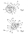
- the radial shaft 15b passes through the outer shell 11 under which it is fixedly connected to a transverse leg 19 provided with a nipple or pin 21 sliding in the groove, or groove 23 of a ring 25 ( Figures 2 and 3 ).
- the groove 23 extends over the entire outer periphery of the ring and in a radial plane to the axis 5a, concentrically.
- the ring 25 is traversed by an oblong hole (or preferably two diametrically opposed holes) 29 in which (each of which) moves a finger 31 ( Figures 2 and 3 ).
- the oblong hole 29 has its axis of elongation parallel to the circular groove 23.
- the finger 31 is an element of a cam (or eccentric) radial device 33 driven by an angle gear 35 controlled by the output shaft 37 (parallel to the axis 5a) of an electric motor 39.
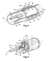
- the shaft 37 is more precisely controlled by a geared motor which rotates an axial screw 41 on which meshes the radial toothed wheel 43, thus defining the angle gear 35 ( figures 3 and 5 ).
- the wheel is extended on either side by an eccentric rod which, with its finger 31, defines the radial cam device 33 ( figure 5 ).
- This device is moved by a shaft 45 (extending in a radial plane to the axis 5a) rotating about its axis 33a and guided by the wheel 43 which rolls in a slot 47 parallel to the axis 5a, under control of the output shaft 37 ( figure 3 ).
- the rings 25, 49, 51 are offset along the axis 5a, as are the three wings (see FIG. figures 1 , 4 and 5 together).
- each wing can thus be adapted according to the situation.
- the upper wing 7a is rotated about its axis 13a, likewise for the two lower wings 7b, 7c (in opposite directions to each other) in order to cancel the moment along the axis 5a in order to keep the entire system upright.
- the resulting applied force is directed laterally with respect to the axis 5a, to the left or right.
- the fixed central portion 9 of the body 5 is provided, at its opposite longitudinal ends, respectively of a first and a second connecting end 53, 55 designed to engage complementary ends provided on the corresponding ends of said upstream and downstream sections 10, 20 of the towed object.
- the outer shell 11 and the wings 7a, 7b, 7c are separable from the part 9 inside the body.
- the wings and the inner part 9 may comprise a removable interlocking system, is known (eg a bayonet system, or a screw connection).
- the outer shell 11 it is advantageously made of two half-shells 11a, 11b joined together in a plane containing the axis 5a and again connected by a removable interlocking system, known per se.
- the device 1 thus provides inter alia a depth control by generating a vertical force on the towed object (at least the sections that are adjacent thereto) to establish at least these sections to a predefined depth.
- the depth control is preferably a local control using a pressure signal.
- This signal may be provided by a local pressure sensor 61 disposed inside the device 1 (body 9, and more particularly zone 9a reserved for electronics on the figure 4 ).
- Another possibility is to use a pressure signal supplied from the outside, for example by a cable connected to the electronics of the device 1. It is then possible to use a sensor arranged remotely and communicating with the electronic processing unit (or microcontroller 60 shown figure 6 ) and of course connected to control means of the inclination of wings already detailed.
- Each wing is also advantageously connected to a position sensor 62 housed at 9a and measuring the angle of inclination (absolute angle) of each wing around its radial axis.
- This position information is loaded into the on-board electronics (microcontroller 60) for control by a control loop.
- the on-board electronics loads into memory data relating to the towed object line which is substantially parallel to it (if such a line exists), so that the device concerned is adapted to apply, (via the wings moved by their actuators 63; figures 5 and 6 ) a lateral force to the adjacent sections on which it can act, to adapt the relative distance with the line (s) close (s).
- the distance data may in particular be provided by a sensor, in particular an acoustic sensor 64, supplying these data to the microcontroller 60, by any appropriate communication means (cable in particular).
- the sensor 64 may be housed at 9a, or located at a distance from the device 1.
- the actuators 63 of the figure 6 relate in particular to the electric motors (such as 39) and the angle and cam (or eccentric) devices 33 presented before (cf. figure 5 ).
- the device 1 comprises three wings
- three motors see figure 4
- three control devices 33, 35 associated with three circular rings (25, 49, 51 on the figure 4 ) sliding parallel to the axis 5a and thus arranged one behind the other, each with an outer peripheral groove (respectively 23, 23 ', 23'') in which moves and turns if necessary the finger of the eccentric corresponding, each ring being traversed, behind, by the light (29, 29 'or 29 ") where engages the finger (31, 31', 31") of the cam 33 concerned.
- the depth control is therefore advantageously provided by a sensor 61 pressure sensitive to the pressure in the environment of the device.
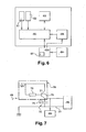
- a power management system 69 (more detailed on the figure 7 ) also makes it possible to escape the problem of the relatively low electric power available.
- the schematic diagram of the figure 7 and the Figures 8 and 9 show that the total cycle of (each) capacitor 70 is Tc + Td (corresponding preferably to the period of acquisition cycles at the input of the acoustic sensor 64).
- each motor (such as 39), here concerned operates at an initial voltage of 12 volts (supplied by a battery of (super) capacitors identified 65 integrated to the interface 67 which receives the data from the sensor 64 to transmit them after treatment to the microcontroller 60, figure 6 for example, between 11 and 12 volts ( figures 7 and 9 ).
- the current source 78 (with for example a storage battery, the transistor 75 and the resistor 79) establishes the maximum current available for the motor 39, when the charge of the capacitor 73 is impairment ( figures 7 and 9 ).
- the discharge in the motors can be triggered / interrupted by comparing the voltage of the capacitors with a theoretical maximum preprogrammed and minimum voltages also predefined.
- a direct measurement can be provided by using a rotary sensor, in particular a Hall-effect non-contact sensor.
- the sensor 62 provided for each wing must be calibrated to operate operationally.
- the two lower wings 7b, 7c are each provided, at their free end, with a heavy mass (lead), respectively 80, 82 on the figure 1 , the upper flange 7a being optionally provided, also at its free end, with a bead 84 enclosing a block of light foam or equivalent, of low density, preferably of lower density than that of water, and therefore floating.
Landscapes
- Engineering & Computer Science (AREA)
- Life Sciences & Earth Sciences (AREA)
- Physics & Mathematics (AREA)
- Mechanical Engineering (AREA)
- General Life Sciences & Earth Sciences (AREA)
- Aviation & Aerospace Engineering (AREA)
- Ocean & Marine Engineering (AREA)
- Combustion & Propulsion (AREA)
- Acoustics & Sound (AREA)
- Environmental & Geological Engineering (AREA)
- Geology (AREA)
- Remote Sensing (AREA)
- Chemical & Material Sciences (AREA)
- General Physics & Mathematics (AREA)
- Geophysics (AREA)
- Oceanography (AREA)
- Control Of Position, Course, Altitude, Or Attitude Of Moving Bodies (AREA)
- Toys (AREA)
- Transmission Devices (AREA)
- Other Liquid Machine Or Engine Such As Wave Power Use (AREA)
- Details Of Aerials (AREA)
- Geophysics And Detection Of Objects (AREA)
- Aiming, Guidance, Guns With A Light Source, Armor, Camouflage, And Targets (AREA)
- Vehicle Cleaning, Maintenance, Repair, Refitting, And Outriggers (AREA)
- Position Fixing By Use Of Radio Waves (AREA)
- Underground Or Underwater Handling Of Building Materials (AREA)
- Catching Or Destruction (AREA)
Claims (18)
- Vorrichtung zum Steuern eines geschleppten Unterwasserobjektes (3), wobei die Vorrichtung umfasst:- einen Körper (5), der eine Längsachse (5a) aufweist und umfasst:* einen inneren Teil (9), der drehfest in Bezug zu dem geschleppten Unterwasserobjekt (3) angeordnet und mit Befestigungsmitteln (53, 55) versehen ist, um ihn demontierbar an dem Objekt zu montieren,* und eine äußere Schale (11), die gegenüber dem festen inneren Teil (9) um die Längsachse (5a) drehbeweglich ist,- mehrere Stabilisationsflügel (7a, 7b, 7c), die jeweils mit dem Körper verbunden sind und sich entlang einer Achse (13a, 13b, 13c) quer zur Längsachse dieses Körpers erstrecken, wobei jeder Flügel in Bezug zum Körper durch Schwenken um seine Querachse mit Hilfe eines Drehantriebssystems (31, 35, 39, 45) und von Steuermitteln (63) ausrichtbar ist, um den Neigungswinkel der Flügel zu verändern, wobei jeder Flügel (7a, 7b, 7c) mit einer Welle (15b) verbunden ist, die sich im Wesentlichen radial in Bezug zur Längsachse (5a) erstreckt, wobei jede Welle (15b) eines Flügels (7a, 7b, 7c) durch die bewegliche äußere Schale (11) hindurchgeht, um mit dieser äußeren Schale und entlang der Längsachse drehbar um den inneren Teil (9), wo die betreffende Welle mit dem System zum Drehantrieb jedes Flügels (7a, 7b, 7c) um seine entsprechende Querachse (13a, 13b, 13c) zusammenwirkt, montiert zu werden,
dadurch gekennzeichnet, dass die Vorrichtung mindestens drei Flügel (7a, 7b, 7c) umfasst, die um die Längsachse angeordnet sind, mit zwei unteren Flügeln, die zwischen sich ein "V" definieren, und einem im Wesentlichen vertikalen oberen Flügel (7a), wobei die Steuermittel (63) auf diese Flügel einwirken, um die Eintauchtiefe und die seitliche Position der Vorrichtung in Bezug zu einer Bezugsachse (5a), entlang der sich das geschleppte Unterwasserobjekt global erstreckt, anzupassen. - Vorrichtung nach Anspruch 1, dadurch gekennzeichnet, dass das Drehantriebssystem der Flügel (7a, 7b, 7c) für jeden Flügel einen Haken (21) umfasst, der mit der Welle (15b) des entsprechenden Flügels zusammenwirkt, wobei der Haken in eine kreisförmige Rille (23, 23', 23") eingreift, die in einem Ring (25, 49, 51) ausgenommen ist, der sich um den festen inneren Teil (9) koaxial erstreckt, wobei der Haken (21) in der Rille gleitet, wenn sich jeder Flügel und die bewegliche äußere Schale um die Längsachse des Körpers (5) drehen.
- Vorrichtung nach einem der vorhergehenden Ansprüche, dadurch gekennzeichnet, dass das Drehantriebssystem jedes Flügels (7a, 7b, 7c), das somit mit dem inneren Teil (9) verbunden ist, mindestens einen Elektromotor (39, 39', 39") umfasst, der in diesem inneren Teil (9) angeordnet ist.
- Vorrichtung nach einem der vorhergehenden Ansprüche, dadurch gekennzeichnet, dass sie eine eingebaute Bearbeitungselektronik (60) umfasst, die in dem inneren Teil (9) angeordnet ist (bei 9a).
- Vorrichtung nach Anspruch 1 oder 2, dadurch gekennzeichnet, dass- sie eine eingebaute Bearbeitungselektronik (60) umfasst und der Drehantrieb jedes Flügels (7a, 7b, 7c) motorisiert ist (39, 39', 39"),- und diese Motorisierung (39, 39', 39") der Flügel sowie die eingebaute Elektronik (60) ausschließlich in dem inneren Teil (9, 9a) des Körpers (5) angeordnet sind, so dass kein Durchgang von elektrischer Leistung oder einer Datenkommunikation zwischen dem inneren Teil (9) und der äußeren Schale (11) des Körpers vorhanden ist.
- Vorrichtung nach einem der vorhergehenden Ansprüche, dadurch gekennzeichnet, dass das Drehantriebssystem jedes Flügels (7a, 7b, 7c) mindestens einen Elektromotor (39, 39', 39") umfasst, der von einer Stromquelle (78) und/oder mit Hilfe von Kondensatoren (65, 73), die in dem inneren Teil (9) angeordnet ist/sind, gespeist wird.
- Vorrichtung nach Anspruch 3 oder 6, dadurch gekennzeichnet, dass der/jeder Elektromotor (39, 39', 39") zum Drehantrieb jedes/der Flügel(s) (7a, 7b, 7c) um seine Querachse intermittierend funktioniert.
- Vorrichtung nach einem der Ansprüche 1 bis 7, dadurch gekennzeichnet, dass die beiden unteren Flügel denselben Winkelabstand zu einer durch den oberen Flügel verlaufenden Vertikale aufweisen.
- Vorrichtung nach einem der Ansprüche 1 bis 7, dadurch gekennzeichnet, dass die Flügel (7a, 7b, 7c) schwer sind und in einem Trieder um die Längsachse (5a) angeordnet sind, wobei die Drehbeweglichkeit der äußeren Schale (11) gegenüber dem festen inneren Teil (9) um diese Längsachse insbesondere im Wasser dem oberen Flügel (7a) eine wesentliche Vertikalität für jede beliebige Ausrichtung des festen inneren Teils um diese Längsachse verleiht.
- Vorrichtung nach Anspruch 2 oder einem der an diesen angeschlossenen Ansprüche 3 bis 7, dadurch gekennzeichnet, dass das Drehantriebssystem jedes Flügels (7a, 7b, 7c) um seine Querachse einen Exzenter (33) umfasst, der an einem ersten Ende mit der Querwelle dieses Flügels und an einem zweiten Ende mit dem Haken (31, 31', 31") verbunden ist, der in der kreisförmigen Rille des entsprechenden Ringes (25, 49, 51) in Eingriff ist, welcher gleitend um den festen inneren Teil (9) koaxial zu diesem montiert ist, so dass die Drehung des betreffenden Flügels um seine Querachse betrachtet durch Verschieben des Ringes entlang der Längsachse des Körpers erfolgt.
- Vorrichtung nach einem der vorhergehenden Ansprüche, dadurch gekennzeichnet, dass der Drehantrieb jedes Flügels (7a, 7b, 7c) um seine Querachse durch eine Nocke (31, 31', 31"; 33) gewährleistet ist, die eine in Bezug zu jener des entsprechenden Flügels versetzte Drehachse besitzt und sich in einer Öffnung (29, 29', 29") bewegt, die sich auf einem Winkelsektor einer im Wesentlichen radialen Ebene zur Längsachse erstreckt, wobei die Nocke von einer Welle (45) bewegt wird, die sich um eine Querachse (33a) zu dieser Längsachse dreht, wobei die Welle von einem Rad (43) angetrieben wird, das in Drehung durch eine Drehvorrichtung mit Winkelumkehr (35) bewegt wird, die selbst von einem drehenden Antriebsmittel (37, 41) angetrieben wird, das sich um eine Achse im Wesentlichen parallel zur Längsachse (5a) des Körpers dreht.
- Vorrichtung nach den Ansprüchen 2 und 11, dadurch gekennzeichnet, dass die drehende Welle (45) an ihrem freien Ende einen Exzenter (31) aufweist, der sich in der Öffnung (29) bewegt und so die Nocke (33) definiert, die die Winkelausrichtung jedes Flügels gewährleistet, wobei die Öffnung in dem Ring (25, 49, 51) ausgenommen ist, der sich um den festen inneren Teil (9) des Körpers (5) erstreckt, so dass die Drehung des betreffenden Flügels um seine Querachse durch Verschieben des Ringes entlang der Längsachse (5a) des Körpers erfolgt.
- Vorrichtung nach einem der vorhergehenden Ansprüche, dadurch gekennzeichnet, dass:- die bewegliche äußere Schale des Körpers zwei voneinander und von dem festen inneren Teil (9) trennbare Halbschalen (11a 11b) umfasst,- und die Drehwelle (15b) jedes Flügels (7a, 7b, 7c) abnehmbar mit dem festen inneren Teil (9) verbunden ist,
so dass die Flügel und die bewegliche äußere Schale (11) des Körpers gegenüber dem inneren Teil dieses Körpers trennbar sind, insbesondere wenn dieser mit dem geschleppten Unterwasserobjekt verbunden ist. - Vorrichtung nach Anspruch 2 oder einem der mit dem Anspruch 2 verbundenen Ansprüche 3 bis 13, dadurch gekennzeichnet, dass sie mindestens ebenso viele kreisförmige Rillen (23, 23', 23") wie Flügel (7a, 7b, 7c) umfasst, wobei diese kreisförmigen Rillen nacheinander entlang der Längsachse (5a) angeordnet sind, so dass die Flügel zueinander entlang dieser Längsachse versetzt sind.
- Vorrichtung nach einem der Ansprüche 3, 5 oder 6, dadurch gekennzeichnet, dass der/jeder Motor (39, 39', 39") intermittierend funktioniert, um den/die betreffenden Flügel abzulenken, wobei der/jeder Motor dazu mit mindestens einem Kondensator (70, 73) verbunden ist, der Lade- und Entladezeiten aufweist, wobei der/jeder Motor während der Entladezeit (Td) des/der Kondensators/-en in Betrieb gesetzt und während seiner/ihrer Ladezeit (Tc) angehalten wird.
- Vorrichtung nach einem der Ansprüche 3, 5 oder 6, dadurch gekennzeichnet, dass die Nutzleistung, um jeden Flügel (7a, 7b, 7c) um seine Querachse zu schwenken, durch mindestens einen Motor (39, 39', 39") geliefert wird, der intermittierend funktioniert, um die Flügel zu bewegen, unter der Steuerung mindestens eines Kondensators (70, 73), der Lade- und Entladezeiten aufweist, wobei der Motor während der Entladezeit (Td) des/der Kondensators/-en in Betrieb gesetzt und während seiner/ihrer Ladezeit (Tc) angehalten wird.
- Vorrichtung nach einem der Ansprüche 15 oder 16, dadurch gekennzeichnet, dass der Kondensator (73) einer elektrischen Schaltung, umfassend eine einstellbare Stromquelle, angehört.
- Vorrichtung nach einem der vorhergehenden Ansprüche, dadurch gekennzeichnet, dass ein Absolutwinkelsensor (62) in dem festen inneren Teil (9) des Körpers angeordnet ist, um den Ausrichtungswinkel jedes Flügels (7a, 7b, 7c) anzuheben.
Applications Claiming Priority (2)
| Application Number | Priority Date | Filing Date | Title |
|---|---|---|---|
| FR0405430 | 2004-05-18 | ||
| FR0405430A FR2870509B1 (fr) | 2004-05-18 | 2004-05-18 | Dispositif de controle de la navigation d'un objet sous-marin remorque |
Publications (3)
| Publication Number | Publication Date |
|---|---|
| EP1598265A2 EP1598265A2 (de) | 2005-11-23 |
| EP1598265A3 EP1598265A3 (de) | 2014-01-01 |
| EP1598265B1 true EP1598265B1 (de) | 2015-05-06 |
Family
ID=34942265
Family Applications (1)
| Application Number | Title | Priority Date | Filing Date |
|---|---|---|---|
| EP20050291003 Expired - Lifetime EP1598265B1 (de) | 2004-05-18 | 2005-05-10 | Vorrichtung zum Steuern eines geschleppten Unterwasserobjektes |
Country Status (5)
| Country | Link |
|---|---|
| US (1) | US7267070B2 (de) |
| EP (1) | EP1598265B1 (de) |
| CN (1) | CN100534857C (de) |
| FR (1) | FR2870509B1 (de) |
| NO (1) | NO337743B1 (de) |
Families Citing this family (21)
| Publication number | Priority date | Publication date | Assignee | Title |
|---|---|---|---|---|
| US7933163B2 (en) * | 2006-07-07 | 2011-04-26 | Kongsberg Seatex As | Method and system for controlling the position of marine seismic streamers |
| FR2903655B1 (fr) | 2006-07-13 | 2009-04-17 | Cybernetix Sa | Dispositif de stabilisation dynamique d'un engin sous-marin. |
| FR2917063B1 (fr) | 2007-06-07 | 2009-12-04 | Cybernetix | Dispositif de fermeture d'un fuselage lie a un objet sous-marin remorque et engin ainsi equipe |
| US8976622B2 (en) | 2008-04-21 | 2015-03-10 | Pgs Geophysical As | Methods for controlling towed marine sensor array geometry |
| FR2940838B1 (fr) | 2009-01-05 | 2012-12-28 | Michel Manin | Procede et dispositif ameliores de prospection sismique marine |
| FR2947390B1 (fr) * | 2009-06-30 | 2011-07-01 | Sercel Rech Const Elect | Procede d'aide au positionnement d'antennes acoustiques lineaires remorquees, comprenant une etape de definition et une etape de generation de cyvles acoustiques distincts |
| NO332115B1 (no) * | 2009-07-07 | 2012-06-25 | Kongsberg Seatex As | Styringsinnretning for posisjonering av instrumentert tauet kabel i vann |
| FR2961317B1 (fr) | 2010-06-10 | 2014-01-17 | Kietta | Procede de prospection sismique en milieu aquatique |
| US8792297B2 (en) | 2010-07-02 | 2014-07-29 | Pgs Geophysical As | Methods for gathering marine geophysical data |
| US9130264B2 (en) | 2012-05-09 | 2015-09-08 | Jeffrey Gervais | Apparatus for raising and lowering antennae |
| US9423527B2 (en) | 2013-03-08 | 2016-08-23 | Cgg Services Sa | Autonomous cleaning device for seismic streamers and method |
| US9375763B2 (en) | 2013-03-08 | 2016-06-28 | Cgg Services Sa | Autonomous cleaning device for seismic streamers and method |
| EP2857869B1 (de) * | 2013-10-07 | 2023-05-03 | Sercel | Betriebsverwaltungssystem zur Ansteuerung einer Navigationssteuerungsvorrichtung entsprechend eines herabgestuften Betriebsmodus |
| CN105129055B (zh) * | 2015-09-09 | 2017-03-29 | 北京南风科创应用技术有限公司 | 一种rov和一种水下扫描方法 |
| FR3043791B1 (fr) | 2015-11-17 | 2018-11-16 | Kietta | Controle de la profondeur d'un cable sismique |
| FR3054890B1 (fr) | 2016-08-02 | 2019-07-05 | Kietta | Controle de la position horizontale d’un cable sismique |
| JP6979828B2 (ja) * | 2017-08-22 | 2021-12-15 | 株式会社日立製作所 | 水中観測装置 |
| CN108545162B (zh) * | 2018-06-20 | 2023-04-28 | 天津中德应用技术大学 | 基于水射流驱动的水下滑翔机器人 |
| CN112703428B (zh) * | 2018-07-10 | 2026-04-24 | 离子地球物理学公司 | 用于地震拖缆装置的闩锁机构 |
| CN113734392A (zh) * | 2021-09-18 | 2021-12-03 | 深圳先进技术研究院 | 舵控操纵装置及方法 |
| CN115535156B (zh) * | 2022-10-18 | 2025-04-25 | 中船黄埔文冲船舶有限公司 | 一种海补管偏向浮力装置及其使用方法 |
Family Cites Families (6)
| Publication number | Priority date | Publication date | Assignee | Title |
|---|---|---|---|---|
| US3943483A (en) * | 1974-05-08 | 1976-03-09 | Western Geophysical Company Of America | Depth controllers for seismic streamer cables with dimension variable lift-producing means |
| AU722852B2 (en) * | 1995-09-22 | 2000-08-10 | Ion Geophysical Corporation | Coil support device for an underwater cable |
| FR2744870B1 (fr) * | 1996-02-13 | 1998-03-06 | Thomson Csf | Procede pour controler la navigation d'une antenne acoustique lineaire remorquee, et dispositifs pour la mise en oeuvre d'un tel procede |
| GB9821277D0 (en) * | 1998-10-01 | 1998-11-25 | Geco As | Seismic data acquisition equipment control system |
| US6011752A (en) * | 1998-08-03 | 2000-01-04 | Western Atlas International, Inc. | Seismic streamer position control module |
| GB9913864D0 (en) * | 1999-06-15 | 1999-08-11 | Shattock Bernard A | Hydrofoil apparatus |
-
2004
- 2004-05-18 FR FR0405430A patent/FR2870509B1/fr not_active Expired - Fee Related
-
2005
- 2005-05-10 EP EP20050291003 patent/EP1598265B1/de not_active Expired - Lifetime
- 2005-05-11 NO NO20052315A patent/NO337743B1/no not_active IP Right Cessation
- 2005-05-18 CN CN200510072723.3A patent/CN100534857C/zh not_active Expired - Fee Related
- 2005-05-18 US US11/131,297 patent/US7267070B2/en not_active Expired - Lifetime
Also Published As
| Publication number | Publication date |
|---|---|
| EP1598265A3 (de) | 2014-01-01 |
| NO337743B1 (no) | 2016-06-13 |
| CN1699111A (zh) | 2005-11-23 |
| NO20052315D0 (no) | 2005-05-11 |
| EP1598265A2 (de) | 2005-11-23 |
| CN100534857C (zh) | 2009-09-02 |
| FR2870509A1 (fr) | 2005-11-25 |
| FR2870509B1 (fr) | 2007-08-17 |
| US20050268835A1 (en) | 2005-12-08 |
| US7267070B2 (en) | 2007-09-11 |
| NO20052315L (no) | 2005-11-21 |
| HK1085175A1 (zh) | 2006-08-18 |
Similar Documents
| Publication | Publication Date | Title |
|---|---|---|
| EP1598265B1 (de) | Vorrichtung zum Steuern eines geschleppten Unterwasserobjektes | |
| FR2651201A1 (fr) | Vehicule a chenilles inclinables. | |
| FR3094151A3 (fr) | Systeme de recharge sans fil, station de recharge sans fil et vehicule | |
| WO1997030361A1 (fr) | Procede pour controler la navigation d'une antenne acoustique lineaire remorquee, et dispositifs pour la mise en ×uvre d'un tel procede | |
| FR2968345A1 (fr) | Dispositif de motorisation de panneaux mobiles et agencement de panneaux equipes de ce dispositif | |
| FR2845048A1 (fr) | Appareil a phare de vehicule oriente horizontalement et verticalement | |
| CA2803739C (fr) | Alimentation electrique des equipements portes par un support rotatif | |
| FR3049572B1 (fr) | Systeme de commande de pas d'helice | |
| CA3106491C (fr) | Dispositif roulant adapte a rouler sur un sol | |
| EP2148413B1 (de) | Integriertes lineares elektrisches Stellglied | |
| WO2014207327A1 (fr) | Contacteur tournant pour une colonne de direction de véhicule automobile | |
| CA2475022C (fr) | Procede de freinage et frein electromecanique mettant en oeuvre ledit procede | |
| CA2845205C (fr) | Actionneur electromecanique pour frein | |
| EP3168126A1 (de) | Tragflügel in form eines umgedrehten t, der angepasst ist, um auf einem boot installiert zu werden | |
| WO2018189259A1 (fr) | Dispositif de déploiement | |
| FR2993911A1 (fr) | Dispositif d'aide a l'enroulement/deroulement d'une couverture souple au-dessus d'un bassin de piscine | |
| EP3739149A1 (de) | Automatische aufrollvorrichtung | |
| FR2498379A1 (fr) | Dispositif d'orientation selon deux axes orthogonaux, utilisation dans une antenne hyperfrequence et antenne hyperfrequence comportant un tel dispositif | |
| EP3562741A1 (de) | Antriebsvorrichtung | |
| FR3063963A1 (fr) | Appareil de manutention a assistance electrique et conducteur a pied | |
| EP3660353B1 (de) | Kraftsensor für stellglied mit kabel und verfahren | |
| FR2776858A1 (fr) | Dispositif de maintien, de positionnement, ou de serrage, a actionnement electrique | |
| FR2552387A1 (fr) | Commande assistee de direction en particulier pour vehicules automobiles | |
| EP3772804A1 (de) | Motorisierungs- und antriebseinheit einer abdeckung für ein schwimmbadbecken | |
| WO2015170019A1 (fr) | Treuil modulaire embarque |
Legal Events
| Date | Code | Title | Description |
|---|---|---|---|
| PUAI | Public reference made under article 153(3) epc to a published international application that has entered the european phase |
Free format text: ORIGINAL CODE: 0009012 |
|
| AK | Designated contracting states |
Kind code of ref document: A2 Designated state(s): AT BE BG CH CY CZ DE DK EE ES FI FR GB GR HU IE IS IT LI LT LU MC NL PL PT RO SE SI SK TR |
|
| AX | Request for extension of the european patent |
Extension state: AL BA HR LV MK YU |
|
| RAP1 | Party data changed (applicant data changed or rights of an application transferred) |
Owner name: SERCEL |
|
| PUAL | Search report despatched |
Free format text: ORIGINAL CODE: 0009013 |
|
| AK | Designated contracting states |
Kind code of ref document: A3 Designated state(s): AT BE BG CH CY CZ DE DK EE ES FI FR GB GR HU IE IS IT LI LT LU MC NL PL PT RO SE SI SK TR |
|
| AX | Request for extension of the european patent |
Extension state: AL BA HR LV MK YU |
|
| RIC1 | Information provided on ipc code assigned before grant |
Ipc: B63G 8/42 20060101ALI20131127BHEP Ipc: B63B 21/66 20060101AFI20131127BHEP |
|
| 17P | Request for examination filed |
Effective date: 20140515 |
|
| RBV | Designated contracting states (corrected) |
Designated state(s): AT BE BG CH CY CZ DE DK EE ES FI FR GB GR HU IE IS IT LI LT LU MC NL PL PT RO SE SI SK TR |
|
| 17Q | First examination report despatched |
Effective date: 20140708 |
|
| AKX | Designation fees paid |
Designated state(s): AT BE BG CH CY CZ DE DK EE ES FI FR GB GR HU IE IS IT LI LT LU MC NL PL PT RO SE SI SK TR |
|
| GRAP | Despatch of communication of intention to grant a patent |
Free format text: ORIGINAL CODE: EPIDOSNIGR1 |
|
| INTG | Intention to grant announced |
Effective date: 20141205 |
|
| GRAS | Grant fee paid |
Free format text: ORIGINAL CODE: EPIDOSNIGR3 |
|
| GRAA | (expected) grant |
Free format text: ORIGINAL CODE: 0009210 |
|
| AK | Designated contracting states |
Kind code of ref document: B1 Designated state(s): AT BE BG CH CY CZ DE DK EE ES FI FR GB GR HU IE IS IT LI LT LU MC NL PL PT RO SE SI SK TR |
|
| REG | Reference to a national code |
Ref country code: GB Ref legal event code: FG4D Free format text: NOT ENGLISH |
|
| REG | Reference to a national code |
Ref country code: CH Ref legal event code: EP |
|
| REG | Reference to a national code |
Ref country code: FR Ref legal event code: PLFP Year of fee payment: 11 |
|
| REG | Reference to a national code |
Ref country code: IE Ref legal event code: FG4D Free format text: LANGUAGE OF EP DOCUMENT: FRENCH |
|
| REG | Reference to a national code |
Ref country code: AT Ref legal event code: REF Ref document number: 725482 Country of ref document: AT Kind code of ref document: T Effective date: 20150615 |
|
| REG | Reference to a national code |
Ref country code: DE Ref legal event code: R096 Ref document number: 602005046488 Country of ref document: DE Effective date: 20150618 |
|
| REG | Reference to a national code |
Ref country code: AT Ref legal event code: MK05 Ref document number: 725482 Country of ref document: AT Kind code of ref document: T Effective date: 20150506 |
|
| REG | Reference to a national code |
Ref country code: NL Ref legal event code: MP Effective date: 20150506 |
|
| REG | Reference to a national code |
Ref country code: LT Ref legal event code: MG4D |
|
| PG25 | Lapsed in a contracting state [announced via postgrant information from national office to epo] |
Ref country code: LT Free format text: LAPSE BECAUSE OF FAILURE TO SUBMIT A TRANSLATION OF THE DESCRIPTION OR TO PAY THE FEE WITHIN THE PRESCRIBED TIME-LIMIT Effective date: 20150506 Ref country code: FI Free format text: LAPSE BECAUSE OF FAILURE TO SUBMIT A TRANSLATION OF THE DESCRIPTION OR TO PAY THE FEE WITHIN THE PRESCRIBED TIME-LIMIT Effective date: 20150506 Ref country code: ES Free format text: LAPSE BECAUSE OF FAILURE TO SUBMIT A TRANSLATION OF THE DESCRIPTION OR TO PAY THE FEE WITHIN THE PRESCRIBED TIME-LIMIT Effective date: 20150506 Ref country code: PT Free format text: LAPSE BECAUSE OF FAILURE TO SUBMIT A TRANSLATION OF THE DESCRIPTION OR TO PAY THE FEE WITHIN THE PRESCRIBED TIME-LIMIT Effective date: 20150907 |
|
| PG25 | Lapsed in a contracting state [announced via postgrant information from national office to epo] |
Ref country code: BG Free format text: LAPSE BECAUSE OF FAILURE TO SUBMIT A TRANSLATION OF THE DESCRIPTION OR TO PAY THE FEE WITHIN THE PRESCRIBED TIME-LIMIT Effective date: 20150806 Ref country code: AT Free format text: LAPSE BECAUSE OF FAILURE TO SUBMIT A TRANSLATION OF THE DESCRIPTION OR TO PAY THE FEE WITHIN THE PRESCRIBED TIME-LIMIT Effective date: 20150506 Ref country code: GR Free format text: LAPSE BECAUSE OF FAILURE TO SUBMIT A TRANSLATION OF THE DESCRIPTION OR TO PAY THE FEE WITHIN THE PRESCRIBED TIME-LIMIT Effective date: 20150807 Ref country code: IS Free format text: LAPSE BECAUSE OF FAILURE TO SUBMIT A TRANSLATION OF THE DESCRIPTION OR TO PAY THE FEE WITHIN THE PRESCRIBED TIME-LIMIT Effective date: 20150906 |
|
| REG | Reference to a national code |
Ref country code: DE Ref legal event code: R119 Ref document number: 602005046488 Country of ref document: DE |
|
| REG | Reference to a national code |
Ref country code: CH Ref legal event code: PL |
|
| PG25 | Lapsed in a contracting state [announced via postgrant information from national office to epo] |
Ref country code: EE Free format text: LAPSE BECAUSE OF FAILURE TO SUBMIT A TRANSLATION OF THE DESCRIPTION OR TO PAY THE FEE WITHIN THE PRESCRIBED TIME-LIMIT Effective date: 20150506 Ref country code: LI Free format text: LAPSE BECAUSE OF NON-PAYMENT OF DUE FEES Effective date: 20150531 Ref country code: CH Free format text: LAPSE BECAUSE OF NON-PAYMENT OF DUE FEES Effective date: 20150531 Ref country code: DK Free format text: LAPSE BECAUSE OF FAILURE TO SUBMIT A TRANSLATION OF THE DESCRIPTION OR TO PAY THE FEE WITHIN THE PRESCRIBED TIME-LIMIT Effective date: 20150506 Ref country code: IT Free format text: LAPSE BECAUSE OF FAILURE TO SUBMIT A TRANSLATION OF THE DESCRIPTION OR TO PAY THE FEE WITHIN THE PRESCRIBED TIME-LIMIT Effective date: 20150506 |
|
| REG | Reference to a national code |
Ref country code: IE Ref legal event code: MM4A |
|
| PG25 | Lapsed in a contracting state [announced via postgrant information from national office to epo] |
Ref country code: SK Free format text: LAPSE BECAUSE OF FAILURE TO SUBMIT A TRANSLATION OF THE DESCRIPTION OR TO PAY THE FEE WITHIN THE PRESCRIBED TIME-LIMIT Effective date: 20150506 Ref country code: RO Free format text: LAPSE BECAUSE OF NON-PAYMENT OF DUE FEES Effective date: 20150506 Ref country code: PL Free format text: LAPSE BECAUSE OF FAILURE TO SUBMIT A TRANSLATION OF THE DESCRIPTION OR TO PAY THE FEE WITHIN THE PRESCRIBED TIME-LIMIT Effective date: 20150506 Ref country code: CZ Free format text: LAPSE BECAUSE OF FAILURE TO SUBMIT A TRANSLATION OF THE DESCRIPTION OR TO PAY THE FEE WITHIN THE PRESCRIBED TIME-LIMIT Effective date: 20150506 Ref country code: MC Free format text: LAPSE BECAUSE OF FAILURE TO SUBMIT A TRANSLATION OF THE DESCRIPTION OR TO PAY THE FEE WITHIN THE PRESCRIBED TIME-LIMIT Effective date: 20150506 |
|
| PLBE | No opposition filed within time limit |
Free format text: ORIGINAL CODE: 0009261 |
|
| STAA | Information on the status of an ep patent application or granted ep patent |
Free format text: STATUS: NO OPPOSITION FILED WITHIN TIME LIMIT |
|
| 26N | No opposition filed |
Effective date: 20160209 |
|
| PG25 | Lapsed in a contracting state [announced via postgrant information from national office to epo] |
Ref country code: DE Free format text: LAPSE BECAUSE OF NON-PAYMENT OF DUE FEES Effective date: 20151201 Ref country code: IE Free format text: LAPSE BECAUSE OF NON-PAYMENT OF DUE FEES Effective date: 20150510 |
|
| REG | Reference to a national code |
Ref country code: FR Ref legal event code: PLFP Year of fee payment: 12 |
|
| PG25 | Lapsed in a contracting state [announced via postgrant information from national office to epo] |
Ref country code: SI Free format text: LAPSE BECAUSE OF FAILURE TO SUBMIT A TRANSLATION OF THE DESCRIPTION OR TO PAY THE FEE WITHIN THE PRESCRIBED TIME-LIMIT Effective date: 20150506 |
|
| REG | Reference to a national code |
Ref country code: FR Ref legal event code: PLFP Year of fee payment: 13 |
|
| PG25 | Lapsed in a contracting state [announced via postgrant information from national office to epo] |
Ref country code: HU Free format text: LAPSE BECAUSE OF FAILURE TO SUBMIT A TRANSLATION OF THE DESCRIPTION OR TO PAY THE FEE WITHIN THE PRESCRIBED TIME-LIMIT; INVALID AB INITIO Effective date: 20050510 |
|
| PG25 | Lapsed in a contracting state [announced via postgrant information from national office to epo] |
Ref country code: CY Free format text: LAPSE BECAUSE OF FAILURE TO SUBMIT A TRANSLATION OF THE DESCRIPTION OR TO PAY THE FEE WITHIN THE PRESCRIBED TIME-LIMIT Effective date: 20150506 Ref country code: SE Free format text: LAPSE BECAUSE OF FAILURE TO SUBMIT A TRANSLATION OF THE DESCRIPTION OR TO PAY THE FEE WITHIN THE PRESCRIBED TIME-LIMIT Effective date: 20150506 Ref country code: NL Free format text: LAPSE BECAUSE OF FAILURE TO SUBMIT A TRANSLATION OF THE DESCRIPTION OR TO PAY THE FEE WITHIN THE PRESCRIBED TIME-LIMIT Effective date: 20150506 |
|
| PG25 | Lapsed in a contracting state [announced via postgrant information from national office to epo] |
Ref country code: BE Free format text: LAPSE BECAUSE OF NON-PAYMENT OF DUE FEES Effective date: 20150531 |
|
| PG25 | Lapsed in a contracting state [announced via postgrant information from national office to epo] |
Ref country code: TR Free format text: LAPSE BECAUSE OF FAILURE TO SUBMIT A TRANSLATION OF THE DESCRIPTION OR TO PAY THE FEE WITHIN THE PRESCRIBED TIME-LIMIT Effective date: 20150506 |
|
| PG25 | Lapsed in a contracting state [announced via postgrant information from national office to epo] |
Ref country code: LU Free format text: LAPSE BECAUSE OF NON-PAYMENT OF DUE FEES Effective date: 20150510 |
|
| REG | Reference to a national code |
Ref country code: FR Ref legal event code: PLFP Year of fee payment: 14 |
|
| PGFP | Annual fee paid to national office [announced via postgrant information from national office to epo] |
Ref country code: FR Payment date: 20190523 Year of fee payment: 15 |
|
| PGFP | Annual fee paid to national office [announced via postgrant information from national office to epo] |
Ref country code: GB Payment date: 20190521 Year of fee payment: 15 |
|
| GBPC | Gb: european patent ceased through non-payment of renewal fee |
Effective date: 20200510 |
|
| PG25 | Lapsed in a contracting state [announced via postgrant information from national office to epo] |
Ref country code: GB Free format text: LAPSE BECAUSE OF NON-PAYMENT OF DUE FEES Effective date: 20200510 Ref country code: FR Free format text: LAPSE BECAUSE OF NON-PAYMENT OF DUE FEES Effective date: 20200531 |