EP1598041B1 - Wheelchair - Google Patents
Wheelchair Download PDFInfo
- Publication number
- EP1598041B1 EP1598041B1 EP05004675A EP05004675A EP1598041B1 EP 1598041 B1 EP1598041 B1 EP 1598041B1 EP 05004675 A EP05004675 A EP 05004675A EP 05004675 A EP05004675 A EP 05004675A EP 1598041 B1 EP1598041 B1 EP 1598041B1
- Authority
- EP
- European Patent Office
- Prior art keywords
- steering wheel
- steering
- wheelchair according
- wheelchair
- tube
- Prior art date
- Legal status (The legal status is an assumption and is not a legal conclusion. Google has not performed a legal analysis and makes no representation as to the accuracy of the status listed.)
- Not-in-force
Links
Images

Classifications
-
- A—HUMAN NECESSITIES
- A61—MEDICAL OR VETERINARY SCIENCE; HYGIENE
- A61G—TRANSPORT, PERSONAL CONVEYANCES, OR ACCOMMODATION SPECIALLY ADAPTED FOR PATIENTS OR DISABLED PERSONS; OPERATING TABLES OR CHAIRS; CHAIRS FOR DENTISTRY; FUNERAL DEVICES
- A61G5/00—Chairs or personal conveyances specially adapted for patients or disabled persons, e.g. wheelchairs
- A61G5/10—Parts, details or accessories
- A61G5/1056—Arrangements for adjusting the seat
- A61G5/1059—Arrangements for adjusting the seat adjusting the height of the seat
-
- A—HUMAN NECESSITIES
- A61—MEDICAL OR VETERINARY SCIENCE; HYGIENE
- A61G—TRANSPORT, PERSONAL CONVEYANCES, OR ACCOMMODATION SPECIALLY ADAPTED FOR PATIENTS OR DISABLED PERSONS; OPERATING TABLES OR CHAIRS; CHAIRS FOR DENTISTRY; FUNERAL DEVICES
- A61G5/00—Chairs or personal conveyances specially adapted for patients or disabled persons, e.g. wheelchairs
- A61G5/10—Parts, details or accessories
- A61G5/1054—Large wheels, e.g. higher than the seat portion
-
- A—HUMAN NECESSITIES
- A61—MEDICAL OR VETERINARY SCIENCE; HYGIENE
- A61G—TRANSPORT, PERSONAL CONVEYANCES, OR ACCOMMODATION SPECIALLY ADAPTED FOR PATIENTS OR DISABLED PERSONS; OPERATING TABLES OR CHAIRS; CHAIRS FOR DENTISTRY; FUNERAL DEVICES
- A61G5/00—Chairs or personal conveyances specially adapted for patients or disabled persons, e.g. wheelchairs
- A61G5/10—Parts, details or accessories
- A61G5/12—Rests specially adapted therefor, e.g. for the head or the feet
- A61G5/128—Rests specially adapted therefor, e.g. for the head or the feet for feet
-
- A—HUMAN NECESSITIES
- A61—MEDICAL OR VETERINARY SCIENCE; HYGIENE
- A61G—TRANSPORT, PERSONAL CONVEYANCES, OR ACCOMMODATION SPECIALLY ADAPTED FOR PATIENTS OR DISABLED PERSONS; OPERATING TABLES OR CHAIRS; CHAIRS FOR DENTISTRY; FUNERAL DEVICES
- A61G5/00—Chairs or personal conveyances specially adapted for patients or disabled persons, e.g. wheelchairs
- A61G5/10—Parts, details or accessories
- A61G5/12—Rests specially adapted therefor, e.g. for the head or the feet
Definitions
- the invention relates to a wheelchair with a frame according to the preamble of the main claim.
- the invention relates to a wheelchair with a frame, at the rear region laterally 'each a drive wheel is mounted and on which at the front of each side a mounted by means of a pivotable steering fork steering wheel or front wheel is mounted.
- Wheelchairs of the type described are known in a variety of embodiments from the prior art. In general, such wheelchairs must be constructed so that they are easily adaptable to the different requirements. These are in particular adjustment options for adapting to different body sizes, different seat heights and different seat depths. It is known to construct wheelchair frame modular. By replacing the modules or changing the assembly of the individual modules, the frame of the wheelchair can be modified accordingly. This approach is associated with a very high assembly costs, has a variety of assembly errors and is unfavorable in terms of manufacturing costs and the cost of the conversion of the frame geometry. The same applies to constructions in which a seat element can be remounted or in which the positions of the individual wheels by changing the articulation of the wheel axles is variable.
- GB 1 321 402 discloses a wheelchair according to the preamble of claim 1.
- the invention has for its object to provide a wheelchair of the type mentioned above, which allows a simple setup and simple, cost manufacturability easy adjustment of different seat heights and seat inclinations.
- the steering fork of the respective steering wheel or front wheel is mounted on a telescopic steering wheel receiving tube which is part-circular arc-shaped, wherein the center of the circular arc is arranged substantially on the axis of rotation of the respective drive wheel (rear wheel).
- the wheelchair according to the invention is characterized by a number of significant advantages.
- the steering-wheel receiving tube comprises an outer, upper telescopic tube which is connected to the frame and an inner, lower telescopic tube guided in this, on which the steering fork is mounted. In this way, the upper portion of the steering wheel receiving tube (outer, upper telescopic tube) can be advantageously integrated into the remaining structure of the frame, without this would affect the adjustability.
- the pivot axis of the steering fork in a substantially vertical orientation on the inner, lower telescopic tube is arranged.
- the pivot axis of the steering fork, about which the front wheel is pivotable does not change its position when the seat height is adjusted by telescoping the steering wheel receiving tube.
- the driving characteristics of the wheelchair thus do not change. This is a very significant advantage that distinguishes the wheelchair according to the invention from the constructions known from the prior art.
- the pivot axis is accommodated in a bearing shell, which is connected to the inner, lower telescopic tube. This results in a stable construction, which does not affect the adjustability and embodiment of the invention Lenkradabilityrohr.
- the invention can thus account for all adjustment measures for adjusting the chassis. Rather, the user of the wheelchair only needs to telescopically adjust the steering wheel receiving tube. This results in a high degree of reliability in the wheelchair according to the invention.
- the wheelchair comprises a seat surface element which is adjustably mounted on the frame. This gives the possibility to make additional adjustment steps.
- the steering wheel receiving tube can also be infinitely adjustable and fixed, for example by means of a clamping device.
- the wheelchair according to the invention comprises a rigid, non-collapsible frame, on each of which a lateral drive wheel 1, which is manually operable, is mounted on its rear regions.
- the wheel axles are mounted on a common axle strut 11. From the axle strut 11 extend lateral spars 12 forward, the front ends are each connected to a steering wheel receiving tube 4 and pass into this.
- To increase the stability contributes to a front cross member 13 at which telescopic footrest struts 14 are mounted, which height adjustable store a common base plate 15.
- the steering wheel receiving tube 4 comprises an outer, upper telescopic tube 6, which is connected via a connecting strut 16 with the respective principal 100°strebe 14.
- an inner, lower telescopic tube 7 is guided telescopically.
- the steering wheel receiving tube 4 is formed in the side view arcuate or part circular arc. As can be seen in particular from FIG. 1 (see radius 17), the center point 5 of the pitch circle of the steering wheel receiving tube 4 lies essentially on the axis of rotation of the drive wheel 1. Telescoping of the steering wheel receiving tube 4 thus leads to a pivoting of the frame or in particular of the spars 12, about the center 5, which coincides with the axis of the drive wheel 1. As a result, the seat height can be adjusted in a particularly simple and effective manner.
- a bearing sleeve 9 is fixed, which supports or defines a pivot axis 8 of a steering fork 2.
- a steering wheel 3 front wheel is rotatably mounted. By pivoting the steering fork 2 is thus a steering of the wheelchair to realize cornering.
- the steering wheel receiving tube 4 is adjustable by means of a step-shaped latching device, not shown in detail.
- a depressible locking button or the like may be provided to allow an adjustment or locking in individual stages. The same applies to the footrest strut 14th
- a seat surface element 10 On the frame of the wheelchair, a seat surface element 10 is mounted, which includes lateral seat stays 18, which merge into spine struts 19, which in turn support a backrest 20.
- the two seat stays 18 are mounted adjustably at their rear end region on a bearing plate 21.
- the bearing plate 21 has a multiplicity of bores (see FIGS. 2 and 3) which can be screwed to a slot rail of the respective seat stay 18 (not shown in detail).
- an angular adjustment of the seat post 18 is possible, which is for this purpose mounted on a front bearing plate to the respective spar 12.
- the bearing plate 22 may also be attached to the seat stays 18.
Abstract
Description
Die Erfindung bezieht sich auf einen Rollstuhl mit einem Rahmen gemäß dem Oberbegriff des Hauptanspruchs.The invention relates to a wheelchair with a frame according to the preamble of the main claim.
Im Einzelnen bezieht sich die Erfindung auf einen Rollstuhl mit einem Rahmen, an dessen hinterem Bereich seitlich' jeweils ein Antriebsrad gelagert ist und an welchem am vorderen Bereich seitlich jeweils ein mittels einer schwenkbaren Lenkgabel gelagertes Lenkrad oder Vorderrad angebracht ist.In detail, the invention relates to a wheelchair with a frame, at the rear region laterally 'each a drive wheel is mounted and on which at the front of each side a mounted by means of a pivotable steering fork steering wheel or front wheel is mounted.
Rollstühle der beschriebenen Art sind in unterschiedlichsten Ausgestaltungsformen aus dem Stand der Technik bekannt. Ganz generell müssen derartige Rollstühle so aufgebaut sein, dass sie in einfacher Weise an die unterschiedlichen Anforderungen anpassbar sind. Dies sind insbesondere Einstellmöglichkeiten zum Anpassen an unterschiedliche Körpergrößen, unterschiedliche Sitzhöhen und unterschiedliche Sitztiefen. Es ist bekannt, Rollstuhlrahmen modular aufzubauen. Durch Austausch der Module bzw. geänderte Montage der einzelnen Module kann der Rahmen des Rollstuhls entsprechend modifiziert werden. Diese Vorgehensweise ist mit einem sehr hohen Montageaufwand verbunden, birgt vielfältige Montagefehler und ist hinsichtlich der Herstellungskosten sowie der Kosten für die Umstellung der Rahmengeometrie ungünstig. Gleiches gilt für Konstruktionen, bei welchen ein Sitzelement ummontiert werden kann oder bei welchen die Positionen der einzelnen Räder durch Änderung der Anlenkung der Radachsen variabel ist. Die GB 1 321 402 offenbart einen Rollstuhl gemäß dem Oberbegriff von Anspruch 1.Wheelchairs of the type described are known in a variety of embodiments from the prior art. In general, such wheelchairs must be constructed so that they are easily adaptable to the different requirements. These are in particular adjustment options for adapting to different body sizes, different seat heights and different seat depths. It is known to construct wheelchair frame modular. By replacing the modules or changing the assembly of the individual modules, the frame of the wheelchair can be modified accordingly. This approach is associated with a very high assembly costs, has a variety of assembly errors and is unfavorable in terms of manufacturing costs and the cost of the conversion of the frame geometry. The same applies to constructions in which a seat element can be remounted or in which the positions of the individual wheels by changing the articulation of the wheel axles is variable. GB 1 321 402 discloses a wheelchair according to the preamble of claim 1.
Der Erfindung liegt die Aufgabe zugrunde, einen Rollstuhl der eingangs genannten Art zu schaffen, welcher bei einfachem Aufbau und einfacher, kostengünstiger Herstellbarkeit eine leichte Einstellung unterschiedlicher Sitzhöhen und Sitzneigungen ermöglicht.The invention has for its object to provide a wheelchair of the type mentioned above, which allows a simple setup and simple, cost manufacturability easy adjustment of different seat heights and seat inclinations.
Erfindungsgemäß wird die Aufgabe durch die Merkmalskombination des Hauptanspruchs gelöst, die Unteransprüche zeigen weitere vorteilhafte Ausgestaltungen der Erfindung.According to the invention the object is achieved by the feature combination of the main claim, the subclaims show further advantageous embodiments of the invention.
Erfindungsgemäß ist somit vorgesehen, dass die Lenkgabel des jeweiligen Lenkrades oder Vorderrades an einem teleskopierbaren Lenkradaufnahmerohr gelagert ist, welches teilkreisbogenförmig ausgebildet ist, wobei der Mittelpunkt des Kreisbogens im Wesentlichen auf der Drehachse des jeweiligen Antriebsrades (Hinterrades) angeordnet ist.According to the invention, it is thus provided that the steering fork of the respective steering wheel or front wheel is mounted on a telescopic steering wheel receiving tube which is part-circular arc-shaped, wherein the center of the circular arc is arranged substantially on the axis of rotation of the respective drive wheel (rear wheel).
Der erfindungsgemäße Rollstuhl zeichnet sich durch eine Reihe erheblicher Vorteile aus.The wheelchair according to the invention is characterized by a number of significant advantages.
Durch die teleskopierbare Ausgestaltung des Lenkradaufnahmerohrs und durch dessen bogenförmige Gestalt verbleibt der Krümmungsmittelpunkt des Lenkradaufnahmerohrs stets unverändert, unabhängig von der Teleskopstellung des Lenkradaufnahmerohrs. Dieses kann somit eingeschoben oder ausgezogen werden, um die gewünschte Sitzhöhe bzw. Neigung der Sitzfläche zu realisieren. Dieser Vorgang kann auch durch ungeübte Bedienungspersonen einfach und schnell durchgeführt werden. Dies ist insbesondere bei Rollstühlen besonders günstig, die nur kurzzeitig von der jeweiligen Person zu benutzen sind. Aufwendige Einstell- und Montageschritte können somit gänzlich entfallen. Besonders günstig ist es, wenn das Lenkradaufnahmerohr ein äußeres, oberes Teleskoprohr umfasst, welches mit dem Rahmen verbunden ist sowie ein in diesem geführtes inneres, unteres Teleskoprohr, an welchem die Lenkgabel gelagert ist. Hierdurch kann der obere Bereich des Lenkradaufnahmerohrs (äußeres, oberes Teleskoprohr) vorteilhaft in den restlichen Aufbau des Rahmens integriert werden, ohne dass hierdurch die Verstellbarkeit beeinträchtigt würde.Due to the telescopic design of the steering wheel receiving tube and the arcuate shape of the center of curvature of the steering wheel receiving tube always remains unchanged, regardless of the telescopic position of the steering wheel receiving tube. This can thus be inserted or withdrawn to realize the desired seat height or inclination of the seat. This process can also be performed easily and quickly by inexperienced operators. This is especially favorable for wheelchairs, which are only to be used by the respective person for a short time. Elaborate adjustment and assembly steps can thus be completely eliminated. It is particularly favorable if the steering-wheel receiving tube comprises an outer, upper telescopic tube which is connected to the frame and an inner, lower telescopic tube guided in this, on which the steering fork is mounted. In this way, the upper portion of the steering wheel receiving tube (outer, upper telescopic tube) can be advantageously integrated into the remaining structure of the frame, without this would affect the adjustability.
Besonders günstig ist es, wenn die Schwenkachse der Lenkgabel in einer im Wesentlichen vertikalen Ausrichtung an dem inneren, unteren Teleskoprohr angeordnet ist. Somit ändert die Schwenkachse der Lenkgabel, um welche das Vorderrad verschwenkbar ist, nicht ihre Position, wenn die Sitzhöhe durch Teleskopieren des Lenkradaufnahmerohrs angepasst wird. Die Fahreigenschaften des Rollstuhls ändern sich somit nicht. Dies ist ein ganz wesentlicher Vorteil, der den erfindungsgemäßen Rollstuhl von den aus dem Stand der Technik bekannten Konstruktionen unterscheidet.It is particularly advantageous if the pivot axis of the steering fork in a substantially vertical orientation on the inner, lower telescopic tube is arranged. Thus, the pivot axis of the steering fork, about which the front wheel is pivotable, does not change its position when the seat height is adjusted by telescoping the steering wheel receiving tube. The driving characteristics of the wheelchair thus do not change. This is a very significant advantage that distinguishes the wheelchair according to the invention from the constructions known from the prior art.
Bevorzugter Weise ist die Schwenkachse in einer Lagerhülle aufgenommen, welche mit dem inneren, unteren Teleskoprohr verbunden ist. Hierdurch ergibt sich eine stabile Konstruktion, die die erfindungsgemäße Verstellbarkeit und Ausgestaltungsform des Lenkradaufnahmerohrs nicht beeinträchtigt.Preferably, the pivot axis is accommodated in a bearing shell, which is connected to the inner, lower telescopic tube. This results in a stable construction, which does not affect the adjustability and embodiment of the invention Lenkradaufnahmerohr.
Erfindungsgemäß können somit sämtliche Einstellmaßnahmen zur Einstellung des Fahrwerks entfallen. Vielmehr braucht der Benutzer des Rollstuhls lediglich das Lenkradaufnahmerohr teleskopisch zu verstellen. Hieraus ergibt sich ein hohes Maß an Betriebssicherheit bei dem erfindungsgemäßen Rollstuhl.According to the invention can thus account for all adjustment measures for adjusting the chassis. Rather, the user of the wheelchair only needs to telescopically adjust the steering wheel receiving tube. This results in a high degree of reliability in the wheelchair according to the invention.
Weiterhin ist es günstig, wenn der Rollstuhl ein Sitzflächenelement umfasst, welches verstellbar an dem Rahmen gelagert ist. Hierdurch ergibt sich die Möglichkeit, zusätzliche Einstellschritte vorzunehmen.Furthermore, it is favorable if the wheelchair comprises a seat surface element which is adjustably mounted on the frame. This gives the possibility to make additional adjustment steps.
Zur einfachen Verstellbarkeit trägt auch bei, wenn das Lenkradaufnahmerohr stufenweise verstellbar ist, bevorzugter Weise mittels einer Rastvorrichtung. Somit werden keine zusätzlichen Werkzeuge benötigt, um die Verstellung vorzunehmen.For ease of adjustment also contributes when the steering wheel receiving tube is gradually adjustable, preferably by means of a locking device. Thus, no additional tools are needed to make the adjustment.
Das Lenkradaufnahmerohr kann auch stufenlos verstellbar sein und beispielsweise mittels einer Klemmeinrichtung fixiert werden.The steering wheel receiving tube can also be infinitely adjustable and fixed, for example by means of a clamping device.
Im Folgenden wird die Erfindung anhand eines Ausführungsbeispiels in Verbindung mit der Zeichnung beschrieben. Dabei zeigt:
- Fig. 1
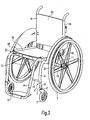
- eine schematische Teil-Seitenansicht eines erfindungsgemäßen Rollstuhls,
- Fig. 2
- eine perspektivische Seiten-Vorderansicht des in Fig. 1 gezeigten Rollstuhls, und
- Fig. 3
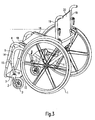
- eine perspektivische Seiten-Rückansicht des erfindungsgemäßen Rollstuhls.
- Fig. 1
- a schematic partial side view of a wheelchair according to the invention,
- Fig. 2
- a side perspective front view of the wheelchair shown in Fig. 1, and
- Fig. 3
- a side perspective rear view of the wheelchair according to the invention.
Der erfindungsgemäße Rollstuhl umfasst einen starren, nicht zusammenlegbaren Rahmen, an welchem an dessen hinteren Bereichen jeweils ein seitliches Antriebsrad 1 gelagert ist, welches manuell betätigbar ist. Die Radachsen sind an einer gemeinsamen Achsstrebe 11 gelagert. Von der Achsstrebe 11 erstrecken sich seitliche Holme 12 nach vorne, deren vordere Enden jeweils mit einem Lenkradaufnahmerohr 4 verbunden sind bzw. in dieses übergehen. Zur Erhöhung der Stabilität trägt eine vordere Querstrebe 13 bei, an welcher teleskopische Fußstützenstreben 14 gelagert sind, welche höheneinstellbar eine gemeinsame Fußplatte 15 lagern.The wheelchair according to the invention comprises a rigid, non-collapsible frame, on each of which a lateral drive wheel 1, which is manually operable, is mounted on its rear regions. The wheel axles are mounted on a
Das Lenkradaufnahmerohr 4 umfasst ein äußeres, oberes Teleskoprohr 6, welches über eine Verbindungsstrebe 16 mit der jeweiligen Fußstützenstrebe 14 verbunden ist. In dem äußeren, oberen Teleskoprohr 6 ist teleskopisch ein inneres, unteres Teleskoprohr 7 geführt.The steering
Das Lenkradaufnahmerohr 4 ist in der Seitenansicht bogenförmig oder teilkreisbogenförmig ausgebildet. Wie insbesondere aus Fig. 1 ersichtlich ist (siehe Radius 17), liegt der Mittelpunkt 5 des Teilkreises des Lenkradaufnahmerohrs 4 im Wesentlichen auf der Drehachse des Antriebsrads 1. Eine Teleskopierung des Lenkradaufnahmerohrs 4 führt somit zu einer Verschwenkung des Rahmens bzw. insbesondere der Holme 12, um den Mittelpunkt 5, der mit der Achse des Antriebsrads 1 zusammenfällt. Hierdurch kann die Sitzhöhe auf besonders einfache und wirksame Weise eingestellt werden.The steering
An dem inneren, unteren Teleskoprohr 7 ist eine Lagerhülse 9 befestigt, welche eine Schwenkachse 8 einer Lenkgabel 2 lagert bzw. definiert. An der Lenkgabel 2 ist drehbar ein Lenkrad 3 (Vorderrad) gelagert. Durch Verschwenkung der Lenkgabel 2 erfolgt somit ein Lenken des Rollstuhls, um Kurvenfahrten zu realisieren.On the inner, lower telescopic tube 7, a bearing sleeve 9 is fixed, which supports or defines a pivot axis 8 of a
Das Lenkradaufnahmerohr 4 ist mittels einer im Einzelnen nicht dargestellten stufenförmigen Verrastungseinrichtung verstellbar. Hierzu kann beispielsweise ein eindrückbarer Sperrknopf oder Ähnliches vorgesehen sein, um eine Verstellung oder Verrastung in einzelnen Stufen zu ermöglichen. Gleiches gilt für die Fußstützenstrebe 14.The steering
An dem Rahmen des Rollstuhls ist ein Sitzflächenelement 10 gelagert, welches seitliche Sitzstreben 18 umfasst, die in Rückenstreben 19 übergehen, welche wiederum eine Rückenlehne 20 lagern. Die beiden Sitzstreben 18 sind an ihrem hinteren Endbereich an einer Lagerplatte 21 verstellbar gelagert. Die Lagerplatte 21 weist hierfür eine Vielzahl von Bohrungen auf (siehe Fig. 2 und 3), welche mit einer im Einzelnen nicht näher gezeigten Langloch-Schiene der jeweiligen Sitzstrebe 18 verschraubt werden kann. Somit ist eine winkelmäßige Einstellung der Sitzstrebe 18 möglich, die hierzu an einer vorderen Lagerplatte an den jeweiligen Holm 12 gelagert ist. Die Lagerplatte 22 kann auch an den Sitzstreben 18 befestigt sein. Somit ist es möglich, die Position des Sitzflächenelements hinsichtlich seiner winkelmäßigen Ausrichtung zu verstellen.On the frame of the wheelchair, a
- 11
- Antriebsraddrive wheel
- 22
- Lenkgabelsteering fork
- 33
- Lenkradsteering wheel
- 44
- LenkradaufnahmerohrSteering wheel holding tube
- 55
- MittelpunktFocus
- 66
- Äußeres, oberes TeleskoprohrOuter, upper telescopic tube
- 77
- Inneres, unteres TeleskoprohrInner, lower telescopic tube
- 88th
- Schwenkachseswivel axis
- 99
- Lagerhülsebearing sleeve
- 1010
- SitzflächenelementSeat element
- 1111
- AchsstrebeTorque rod
- 1212
- HolmHolm
- 1313
- Querstrebecrossmember
- 1414
- FußstützenstrebeFußstützenstrebe
- 1515
- Fußplattefootplate
- 1616
- Verbindungsstrebeconnecting strut
- 1717
- Radiusradius
- 1818
- Sitzstrebeseat stay
- 1919
- Rückenstrebeback strut
- 2020
- Rückenlehnebackrest
- 2121
- Lagerplattebearing plate
- 2222
- Lagerplattebearing plate
Claims (10)
- Wheelchair having a frame, in whose rear region in each case a drive wheel (1) is mounted at the sides and on which, in the front region, a steering wheel (3) is mounted at the sides in each case by means of a pivotable steering fork (2), the steering fork (2) being mounted on a telescopic steering wheel holding tube (4), characterized in that the steering wheel holding tube (4) is formed in the shape of part of a circular arc, the centre (5) of the circular arc being arranged substantially on the axis of rotation of the respective drive wheel (1).
- Wheelchair according to Claim 1, characterized in that the steering wheel holding tube (4) comprises an upright telescopic tube (6) connected to the frame and a lower telescopic tube (7) which is guided in the latter and on which the steering fork (2) is mounted.
- Wheelchair according to Claim 2, characterized in that the pivot axis (8) of the steering fork (2) is arranged in a substantially vertical alignment on the lower telescopic tube (7).
- Wheelchair according to one of Claims 1 to 3, characterized in that the pivot axis (8) of the steering fork (2) is accommodated in a bearing sleeve (9) which is connected to the lower telescopic tube (7).
- Wheelchair according to one of Claims 1 to 3, characterized in that the pivot axis (8) of the steering fork (2) is accommodated in a bearing sleeve (9) which is connected to the steering fork (2).
- Wheelchair according to one of Claims 1 to 5, characterized in that a seating area element (10) is adjustably mounted on the frame.
- Wheelchair according to one of Claims 1 to 6, characterized in that the steering wheel holding tube (4) can be adjusted step by step.
- Wheelchair according to one of Claims 1 to 7, characterized in that the steering wheel holding tube (4) can be adjusted by means of a latching device.
- Wheelchair according to one of Claims 1 to 6, characterized in that the steering wheel holding tube (4) can be adjusted continuously.
- Wheelchair according to one of Claims 1 to 9, characterized in that the steering wheel holding tube can be adjusted by means of a clamp connection.
Applications Claiming Priority (2)
| Application Number | Priority Date | Filing Date | Title |
|---|---|---|---|
| DE202004007928U | 2004-05-17 | ||
| DE202004007928U DE202004007928U1 (en) | 2004-05-17 | 2004-05-17 | wheelchair |
Publications (2)
| Publication Number | Publication Date |
|---|---|
| EP1598041A1 EP1598041A1 (en) | 2005-11-23 |
| EP1598041B1 true EP1598041B1 (en) | 2006-11-08 |
Family
ID=32748667
Family Applications (1)
| Application Number | Title | Priority Date | Filing Date |
|---|---|---|---|
| EP05004675A Not-in-force EP1598041B1 (en) | 2004-05-17 | 2005-03-03 | Wheelchair |
Country Status (5)
| Country | Link |
|---|---|
| EP (1) | EP1598041B1 (en) |
| AT (1) | ATE344650T1 (en) |
| DE (2) | DE202004007928U1 (en) |
| DK (1) | DK1598041T3 (en) |
| ES (1) | ES2277303T3 (en) |
Families Citing this family (4)
| Publication number | Priority date | Publication date | Assignee | Title |
|---|---|---|---|---|
| US8573622B2 (en) | 2006-04-04 | 2013-11-05 | Lu Papi & Associates Pty Ltd | Wheelchair |
| US20110018222A1 (en) | 2007-12-21 | 2011-01-27 | Michael Knopf | Caster Strut, Wheelchair Frame and Wheelchair |
| EP2174630B1 (en) | 2008-10-10 | 2011-01-26 | Sunrise Medical GmbH & Co. KG | Wheelchair comprising a foot support |
| DE102010017958A1 (en) | 2010-04-22 | 2011-10-27 | Dietz Gmbh | Wheelchair for use by people, has driving wheel and steering wheel arranged on sides of frame via pivoting front fork, where fork is supported at receiving element that comprises fixing member connected with bearing shell arranged at frame |
Family Cites Families (2)
| Publication number | Priority date | Publication date | Assignee | Title |
|---|---|---|---|---|
| FI46026C (en) * | 1971-01-11 | 1972-12-11 | Suomen Vanutehdas Finnwad | Wheelchair that can be used on the stairs. |
| US6431650B1 (en) * | 2001-01-26 | 2002-08-13 | Jeremy D. Visone | Height adjustable wheelchair apparatus |
-
2004
- 2004-05-17 DE DE202004007928U patent/DE202004007928U1/en not_active Expired - Lifetime
-
2005
- 2005-03-03 ES ES05004675T patent/ES2277303T3/en active Active
- 2005-03-03 DK DK05004675T patent/DK1598041T3/en active
- 2005-03-03 EP EP05004675A patent/EP1598041B1/en not_active Not-in-force
- 2005-03-03 DE DE502005000169T patent/DE502005000169D1/en active Active
- 2005-03-03 AT AT05004675T patent/ATE344650T1/en active
Also Published As
| Publication number | Publication date |
|---|---|
| DK1598041T3 (en) | 2007-03-05 |
| ES2277303T3 (en) | 2007-07-01 |
| DE202004007928U1 (en) | 2004-07-22 |
| ATE344650T1 (en) | 2006-11-15 |
| EP1598041A1 (en) | 2005-11-23 |
| DE502005000169D1 (en) | 2006-12-21 |
Similar Documents
| Publication | Publication Date | Title |
|---|---|---|
| DE10136368C2 (en) | Small vehicle, especially a wheelchair | |
| EP0887064A2 (en) | Wheelchair with front wheel holder, wheelchair with adjustable inclination of the seat, wheelchair with variable inclination of the back wheel axis, seat module for wheelchair, use of the seat module and use of the wheelchair | |
| DE102004025884B4 (en) | Telescopic bike | |
| EP1598041B1 (en) | Wheelchair | |
| EP1789304B1 (en) | Collapsible frame for a pushchair | |
| EP1279391A2 (en) | Small-sized vehicle, in particular wheelchair | |
| EP2106777B1 (en) | Wheelchair | |
| EP0827729B1 (en) | Wheelchair | |
| DE69921783T2 (en) | WHEELCHAIR AND CONNECTION DEVICE TO BE USED ON A WHEELCHAIR | |
| DE2516513B2 (en) | HAND CART WITH FOLDING WHEELS, IN PARTICULAR GOLF COOKER TROLLEYS | |
| DE202013002877U1 (en) | Wheelchair with adjustable seat unit | |
| EP1534208B1 (en) | Wheelchair, particularly electric wheelchair | |
| DE202006010445U1 (en) | Walking aid comprises a frame with side frames having a front strut supporting a front wheel and which is partially bent | |
| EP1772129B1 (en) | Wheelchair frame | |
| DE202008009608U1 (en) | Folding wheelchair with variable seat width | |
| DE60218731T2 (en) | wheelchair | |
| DE102011050800B4 (en) | Wheelchair, cross strut assembly for a wheelchair and method of adjusting the side frame spacing | |
| EP0824907A1 (en) | Device for adjusting the camber of wheelchairs | |
| EP0538610A1 (en) | Wheelchair | |
| EP1584313B1 (en) | Wheelchair frame | |
| DE202014102088U1 (en) | Scooter and assembly kit for it | |
| EP1516608B1 (en) | Wheelchair frame | |
| DE10343784B3 (en) | Wheelchair has side frames in the form of an arc profile and extending in a partially convex manner above the rear wheel from a rear stanchion to the steering region of the front wheel | |
| DE10338753B4 (en) | stroller | |
| DE19932109C1 (en) | Spring suspension for a wheelchair has a spring joint to support the wheel or wheel structure with a spring unit over the wheel axis which can be fitted to folding wheelchairs |
Legal Events
| Date | Code | Title | Description |
|---|---|---|---|
| PUAI | Public reference made under article 153(3) epc to a published international application that has entered the european phase |
Free format text: ORIGINAL CODE: 0009012 |
|
| 17P | Request for examination filed |
Effective date: 20050908 |
|
| AK | Designated contracting states |
Kind code of ref document: A1 Designated state(s): AT BE BG CH CY CZ DE DK EE ES FI FR GB GR HU IE IS IT LI LT LU MC NL PL PT RO SE SI SK TR |
|
| AX | Request for extension of the european patent |
Extension state: AL BA HR LV MK YU |
|
| GRAP | Despatch of communication of intention to grant a patent |
Free format text: ORIGINAL CODE: EPIDOSNIGR1 |
|
| AKX | Designation fees paid |
Designated state(s): AT BE BG CH CY CZ DE DK EE ES FI FR GB GR HU IE IS IT LI LT LU MC NL PL PT RO SE SI SK TR |
|
| GRAS | Grant fee paid |
Free format text: ORIGINAL CODE: EPIDOSNIGR3 |
|
| GRAA | (expected) grant |
Free format text: ORIGINAL CODE: 0009210 |
|
| AK | Designated contracting states |
Kind code of ref document: B1 Designated state(s): AT BE BG CH CY CZ DE DK EE ES FI FR GB GR HU IE IS IT LI LT LU MC NL PL PT RO SE SI SK TR |
|
| PG25 | Lapsed in a contracting state [announced via postgrant information from national office to epo] |
Ref country code: SK Free format text: LAPSE BECAUSE OF FAILURE TO SUBMIT A TRANSLATION OF THE DESCRIPTION OR TO PAY THE FEE WITHIN THE PRESCRIBED TIME-LIMIT Effective date: 20061108 Ref country code: SI Free format text: LAPSE BECAUSE OF FAILURE TO SUBMIT A TRANSLATION OF THE DESCRIPTION OR TO PAY THE FEE WITHIN THE PRESCRIBED TIME-LIMIT Effective date: 20061108 Ref country code: RO Free format text: LAPSE BECAUSE OF FAILURE TO SUBMIT A TRANSLATION OF THE DESCRIPTION OR TO PAY THE FEE WITHIN THE PRESCRIBED TIME-LIMIT Effective date: 20061108 Ref country code: PL Free format text: LAPSE BECAUSE OF FAILURE TO SUBMIT A TRANSLATION OF THE DESCRIPTION OR TO PAY THE FEE WITHIN THE PRESCRIBED TIME-LIMIT Effective date: 20061108 Ref country code: IE Free format text: LAPSE BECAUSE OF FAILURE TO SUBMIT A TRANSLATION OF THE DESCRIPTION OR TO PAY THE FEE WITHIN THE PRESCRIBED TIME-LIMIT Effective date: 20061108 Ref country code: FI Free format text: LAPSE BECAUSE OF FAILURE TO SUBMIT A TRANSLATION OF THE DESCRIPTION OR TO PAY THE FEE WITHIN THE PRESCRIBED TIME-LIMIT Effective date: 20061108 Ref country code: CZ Free format text: LAPSE BECAUSE OF FAILURE TO SUBMIT A TRANSLATION OF THE DESCRIPTION OR TO PAY THE FEE WITHIN THE PRESCRIBED TIME-LIMIT Effective date: 20061108 |
|
| REG | Reference to a national code |
Ref country code: GB Ref legal event code: FG4D Free format text: NOT ENGLISH |
|
| REG | Reference to a national code |
Ref country code: CH Ref legal event code: EP |
|
| REG | Reference to a national code |
Ref country code: IE Ref legal event code: FG4D Free format text: LANGUAGE OF EP DOCUMENT: GERMAN |
|
| REF | Corresponds to: |
Ref document number: 502005000169 Country of ref document: DE Date of ref document: 20061221 Kind code of ref document: P |
|
| REG | Reference to a national code |
Ref country code: SE Ref legal event code: TRGR |
|
| PG25 | Lapsed in a contracting state [announced via postgrant information from national office to epo] |
Ref country code: BG Free format text: LAPSE BECAUSE OF FAILURE TO SUBMIT A TRANSLATION OF THE DESCRIPTION OR TO PAY THE FEE WITHIN THE PRESCRIBED TIME-LIMIT Effective date: 20070208 |
|
| REG | Reference to a national code |
Ref country code: CH Ref legal event code: NV Representative=s name: KELLER & PARTNER PATENTANWAELTE AG WINTERTHUR |
|
| REG | Reference to a national code |
Ref country code: DK Ref legal event code: T3 |
|
| GBT | Gb: translation of ep patent filed (gb section 77(6)(a)/1977) |
Effective date: 20070213 |
|
| PG25 | Lapsed in a contracting state [announced via postgrant information from national office to epo] |
Ref country code: IS Free format text: LAPSE BECAUSE OF FAILURE TO SUBMIT A TRANSLATION OF THE DESCRIPTION OR TO PAY THE FEE WITHIN THE PRESCRIBED TIME-LIMIT Effective date: 20070308 |
|
| PG25 | Lapsed in a contracting state [announced via postgrant information from national office to epo] |
Ref country code: PT Free format text: LAPSE BECAUSE OF FAILURE TO SUBMIT A TRANSLATION OF THE DESCRIPTION OR TO PAY THE FEE WITHIN THE PRESCRIBED TIME-LIMIT Effective date: 20070409 |
|
| ET | Fr: translation filed | ||
| REG | Reference to a national code |
Ref country code: IE Ref legal event code: FD4D |
|
| REG | Reference to a national code |
Ref country code: ES Ref legal event code: FG2A Ref document number: 2277303 Country of ref document: ES Kind code of ref document: T3 |
|
| PLBE | No opposition filed within time limit |
Free format text: ORIGINAL CODE: 0009261 |
|
| STAA | Information on the status of an ep patent application or granted ep patent |
Free format text: STATUS: NO OPPOSITION FILED WITHIN TIME LIMIT |
|
| 26N | No opposition filed |
Effective date: 20070809 |
|
| PG25 | Lapsed in a contracting state [announced via postgrant information from national office to epo] |
Ref country code: MC Free format text: LAPSE BECAUSE OF NON-PAYMENT OF DUE FEES Effective date: 20070331 |
|
| PG25 | Lapsed in a contracting state [announced via postgrant information from national office to epo] |
Ref country code: GR Free format text: LAPSE BECAUSE OF FAILURE TO SUBMIT A TRANSLATION OF THE DESCRIPTION OR TO PAY THE FEE WITHIN THE PRESCRIBED TIME-LIMIT Effective date: 20070209 |
|
| PG25 | Lapsed in a contracting state [announced via postgrant information from national office to epo] |
Ref country code: LT Free format text: LAPSE BECAUSE OF FAILURE TO SUBMIT A TRANSLATION OF THE DESCRIPTION OR TO PAY THE FEE WITHIN THE PRESCRIBED TIME-LIMIT Effective date: 20061108 |
|
| PG25 | Lapsed in a contracting state [announced via postgrant information from national office to epo] |
Ref country code: EE Free format text: LAPSE BECAUSE OF FAILURE TO SUBMIT A TRANSLATION OF THE DESCRIPTION OR TO PAY THE FEE WITHIN THE PRESCRIBED TIME-LIMIT Effective date: 20061108 |
|
| PG25 | Lapsed in a contracting state [announced via postgrant information from national office to epo] |
Ref country code: LU Free format text: LAPSE BECAUSE OF NON-PAYMENT OF DUE FEES Effective date: 20070303 Ref country code: CY Free format text: LAPSE BECAUSE OF FAILURE TO SUBMIT A TRANSLATION OF THE DESCRIPTION OR TO PAY THE FEE WITHIN THE PRESCRIBED TIME-LIMIT Effective date: 20061108 |
|
| PG25 | Lapsed in a contracting state [announced via postgrant information from national office to epo] |
Ref country code: TR Free format text: LAPSE BECAUSE OF FAILURE TO SUBMIT A TRANSLATION OF THE DESCRIPTION OR TO PAY THE FEE WITHIN THE PRESCRIBED TIME-LIMIT Effective date: 20061108 Ref country code: HU Free format text: LAPSE BECAUSE OF FAILURE TO SUBMIT A TRANSLATION OF THE DESCRIPTION OR TO PAY THE FEE WITHIN THE PRESCRIBED TIME-LIMIT Effective date: 20070509 |
|
| PGFP | Annual fee paid to national office [announced via postgrant information from national office to epo] |
Ref country code: CH Payment date: 20120323 Year of fee payment: 8 |
|
| PGFP | Annual fee paid to national office [announced via postgrant information from national office to epo] |
Ref country code: SE Payment date: 20120322 Year of fee payment: 8 Ref country code: DK Payment date: 20120326 Year of fee payment: 8 Ref country code: GB Payment date: 20120322 Year of fee payment: 8 Ref country code: IT Payment date: 20120324 Year of fee payment: 8 Ref country code: BE Payment date: 20120323 Year of fee payment: 8 |
|
| PGFP | Annual fee paid to national office [announced via postgrant information from national office to epo] |
Ref country code: NL Payment date: 20120327 Year of fee payment: 8 |
|
| PGFP | Annual fee paid to national office [announced via postgrant information from national office to epo] |
Ref country code: AT Payment date: 20120321 Year of fee payment: 8 |
|
| PGFP | Annual fee paid to national office [announced via postgrant information from national office to epo] |
Ref country code: FR Payment date: 20130329 Year of fee payment: 9 |
|
| PGFP | Annual fee paid to national office [announced via postgrant information from national office to epo] |
Ref country code: ES Payment date: 20120326 Year of fee payment: 8 |
|
| REG | Reference to a national code |
Ref country code: DE Ref legal event code: R082 Ref document number: 502005000169 Country of ref document: DE Representative=s name: HOEFER & PARTNER PATENTANWAELTE MBB, DE Ref country code: DE Ref legal event code: R082 Ref document number: 502005000169 Country of ref document: DE Representative=s name: HOEFER & PARTNER, DE Ref country code: DE Ref legal event code: R082 Ref document number: 502005000169 Country of ref document: DE |
|
| BERE | Be: lapsed |
Owner name: MEYRA WILHELM MEYER G.M.B.H. & CO. KG Effective date: 20130331 |
|
| REG | Reference to a national code |
Ref country code: NL Ref legal event code: V1 Effective date: 20131001 |
|
| REG | Reference to a national code |
Ref country code: DK Ref legal event code: EBP Effective date: 20130331 Ref country code: DK Ref legal event code: EBP |
|
| REG | Reference to a national code |
Ref country code: SE Ref legal event code: EUG |
|
| PG25 | Lapsed in a contracting state [announced via postgrant information from national office to epo] |
Ref country code: SE Free format text: LAPSE BECAUSE OF NON-PAYMENT OF DUE FEES Effective date: 20130304 |
|
| REG | Reference to a national code |
Ref country code: CH Ref legal event code: PL |
|
| REG | Reference to a national code |
Ref country code: AT Ref legal event code: MM01 Ref document number: 344650 Country of ref document: AT Kind code of ref document: T Effective date: 20130303 |
|
| GBPC | Gb: european patent ceased through non-payment of renewal fee |
Effective date: 20130303 |
|
| REG | Reference to a national code |
Ref country code: FR Ref legal event code: ST Effective date: 20131129 |
|
| PG25 | Lapsed in a contracting state [announced via postgrant information from national office to epo] |
Ref country code: GB Free format text: LAPSE BECAUSE OF NON-PAYMENT OF DUE FEES Effective date: 20130303 Ref country code: AT Free format text: LAPSE BECAUSE OF NON-PAYMENT OF DUE FEES Effective date: 20130303 Ref country code: LI Free format text: LAPSE BECAUSE OF NON-PAYMENT OF DUE FEES Effective date: 20130331 Ref country code: FR Free format text: LAPSE BECAUSE OF NON-PAYMENT OF DUE FEES Effective date: 20130402 Ref country code: BE Free format text: LAPSE BECAUSE OF NON-PAYMENT OF DUE FEES Effective date: 20130331 Ref country code: CH Free format text: LAPSE BECAUSE OF NON-PAYMENT OF DUE FEES Effective date: 20130331 |
|
| PG25 | Lapsed in a contracting state [announced via postgrant information from national office to epo] |
Ref country code: NL Free format text: LAPSE BECAUSE OF NON-PAYMENT OF DUE FEES Effective date: 20131001 Ref country code: IT Free format text: LAPSE BECAUSE OF NON-PAYMENT OF DUE FEES Effective date: 20130303 |
|
| PG25 | Lapsed in a contracting state [announced via postgrant information from national office to epo] |
Ref country code: DK Free format text: LAPSE BECAUSE OF NON-PAYMENT OF DUE FEES Effective date: 20130331 |
|
| REG | Reference to a national code |
Ref country code: ES Ref legal event code: FD2A Effective date: 20140611 |
|
| PG25 | Lapsed in a contracting state [announced via postgrant information from national office to epo] |
Ref country code: ES Free format text: LAPSE BECAUSE OF NON-PAYMENT OF DUE FEES Effective date: 20130304 |
|
| PGFP | Annual fee paid to national office [announced via postgrant information from national office to epo] |
Ref country code: DE Payment date: 20160331 Year of fee payment: 12 |
|
| REG | Reference to a national code |
Ref country code: DE Ref legal event code: R119 Ref document number: 502005000169 Country of ref document: DE |
|
| PG25 | Lapsed in a contracting state [announced via postgrant information from national office to epo] |
Ref country code: DE Free format text: LAPSE BECAUSE OF NON-PAYMENT OF DUE FEES Effective date: 20171003 |