EP1597642B1 - Pulsausgabefunktion mit linearer frequenzänderung für eine speicherprogrammierbare steuerung - Google Patents
Pulsausgabefunktion mit linearer frequenzänderung für eine speicherprogrammierbare steuerung Download PDFInfo
- Publication number
- EP1597642B1 EP1597642B1 EP04715031A EP04715031A EP1597642B1 EP 1597642 B1 EP1597642 B1 EP 1597642B1 EP 04715031 A EP04715031 A EP 04715031A EP 04715031 A EP04715031 A EP 04715031A EP 1597642 B1 EP1597642 B1 EP 1597642B1
- Authority
- EP
- European Patent Office
- Prior art keywords
- frequency
- pulse
- specified
- user
- time
- Prior art date
- Legal status (The legal status is an assumption and is not a legal conclusion. Google has not performed a legal analysis and makes no representation as to the accuracy of the status listed.)
- Expired - Lifetime
Links
Images


Classifications
-
- G—PHYSICS
- G05—CONTROLLING; REGULATING
- G05B—CONTROL OR REGULATING SYSTEMS IN GENERAL; FUNCTIONAL ELEMENTS OF SUCH SYSTEMS; MONITORING OR TESTING ARRANGEMENTS FOR SUCH SYSTEMS OR ELEMENTS
- G05B19/00—Program-control systems
- G05B19/02—Program-control systems electric
- G05B19/04—Program control other than numerical control, i.e. in sequence controllers or logic controllers
- G05B19/05—Programmable logic controllers, e.g. simulating logic interconnections of signals according to ladder diagrams or function charts
-
- G—PHYSICS
- G05—CONTROLLING; REGULATING
- G05B—CONTROL OR REGULATING SYSTEMS IN GENERAL; FUNCTIONAL ELEMENTS OF SUCH SYSTEMS; MONITORING OR TESTING ARRANGEMENTS FOR SUCH SYSTEMS OR ELEMENTS
- G05B19/00—Program-control systems
- G05B19/02—Program-control systems electric
- G05B19/18—Numerical control [NC], i.e. automatically operating machines, in particular machine tools, e.g. in a manufacturing environment, so as to execute positioning, movement or co-ordinated operations by means of program data in numerical form
- G05B19/416—Numerical control [NC], i.e. automatically operating machines, in particular machine tools, e.g. in a manufacturing environment, so as to execute positioning, movement or co-ordinated operations by means of program data in numerical form characterised by control of velocity, acceleration or deceleration
-
- H—ELECTRICITY
- H02—GENERATION; CONVERSION OR DISTRIBUTION OF ELECTRIC POWER
- H02P—CONTROL OR REGULATION OF ELECTRIC MOTORS, ELECTRIC GENERATORS OR DYNAMO-ELECTRIC CONVERTERS; CONTROLLING TRANSFORMERS, REACTORS OR CHOKE COILS
- H02P8/00—Arrangements for controlling dynamo-electric motors rotating step by step
- H02P8/14—Arrangements for controlling speed or speed and torque
-
- G—PHYSICS
- G05—CONTROLLING; REGULATING
- G05B—CONTROL OR REGULATING SYSTEMS IN GENERAL; FUNCTIONAL ELEMENTS OF SUCH SYSTEMS; MONITORING OR TESTING ARRANGEMENTS FOR SUCH SYSTEMS OR ELEMENTS
- G05B2219/00—Program-control systems
- G05B2219/30—Nc systems
- G05B2219/34—Director, elements to supervisory
- G05B2219/34016—Pulse processor
-
- G—PHYSICS
- G05—CONTROLLING; REGULATING
- G05B—CONTROL OR REGULATING SYSTEMS IN GENERAL; FUNCTIONAL ELEMENTS OF SUCH SYSTEMS; MONITORING OR TESTING ARRANGEMENTS FOR SUCH SYSTEMS OR ELEMENTS
- G05B2219/00—Program-control systems
- G05B2219/30—Nc systems
- G05B2219/41—Servomotor, servo controller till figures
- G05B2219/41276—Displacement as function of width, amplitude pulse to motor
Definitions
- Programmable logic controllers can be supplied with some means of producing pulsed outputs on their discrete output points that can be used for controlling the motion of stepper motors, pulse input controlled servo-motor controllers, and/or for other equipment that is controlled by an input pulse frequency, pulse width, and/or number of pulses.
- a desired motion profile can be described in terms of desired pulse frequency versus time.
- Such profiles can be used in industry to describe, for example, the speed of a motor positioning a tool, where the frequency of pulses delivered to the motor system controls the rotational speed.
- Typical motor systems used in industry today have scaling factors of from 200 to 200000 pulses per revolution.
- Typical acceleration times from minimum to maximum frequency can range from a few milliseconds up to many seconds.
- the actual object of the motion is often to move a specific distance, expressed as a specific number of pulses, while satisfying constraints on acceleration, and change in acceleration.
- Certain exemplary embodiments provide a pulse output function for a programmable logic controller.
- the pulse output function can provide a means for producing a user specified frequency of pulses, for varying the pulse frequency according to a user specified linear rate of change with time (constant acceleration), and/or for varying the frequency in response to a user specified linear variation in acceleration with respect to time.
- the function can provide for user specified pulse frequency output profiles consisting of an indefinitely large and indefinitely intermixed sequence of line segments, each line segment representing an increasing frequency, decreasing frequency, and/or constant frequency output.
- the frequency magnitude, rate, and polarity of change in frequency, and rate and polarity of change in acceleration can be independently specified for each line segment.
- each line segment can be independently specified as a number of pulses, as an indefinite length to be terminated by an external event, and/or as an indefinite length to be terminated by reaching a specific frequency goal.
- the operation of a specified line segment can be interrupted (as, for example, by an emergency stop function). On such line segment interruption, the pulse output can be abruptly terminated, and/or a transition can be ordered to a newly specified line segment (as, for example, an item in an emergency shut-down sequence) without discontinuities in the pulse generation.
- Programmable logic controllers can be supplied with some means of producing pulsed outputs on their discrete output points that can be used for controlling stepper motors, pulse input controlled servo-motor controllers, and/or for other equipment that is controlled by an input pulse frequency, pulse width, and/or number of pulses.
- Programmable logic controllers can focus on user specification of pulse width as a simple implementation.
- Programmable logic controllers can include a means for delivering a sequence of user specifications so as to produce a desired profile of pulse width outputs.
- Programmable logic controllers can include a means of interpolating changes in pulse width between specification points so as to reduce generally undesired discontinuities in pulse width while following a specified ramped change in pulse width.
- pulse width is inversely related to frequency. Mechanisms that depend on pulse width and change in pulse width specification can be inconvenient to use when the user desired specification is in frequency and change in frequency. In particular, in attempting to describe frequency changes with respect to time (acceleration), and changes in acceleration with respect to time, the use of pulse width and change in pulse width specifications can require an inconveniently large number of points to describe a line segment with sufficient accuracy.
- Certain exemplary embodiments can provide dedicated logic to perform these calculations, coupled with input data pipelining mechanisms to allow a consistent supply of timely new data, and state machine logic to manage the calculations, deliver correct calculation results to the pulse generator, and manage transitions between desired operating modes.
- the dedicated logic can use fixed point calculations rather than the generally more complicated and more expensive floating point calculation mechanisms.
- the computation of target frequency and target acceleration at a particular time can be carried out as a cumulative addition of incremental changes. By allowing the rate of such cumulative additions to be independently specified, the fixed point additions can be scaled to cover a range of frequency/time/rate of change values that might otherwise require excessive word length or floating point calculation hardware.
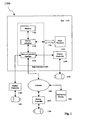
- FIG. 1 is a block diagram of an exemplary embodiment of a system 1000.
- System 1000 can include an information device such as a programmable logic controller ("PLC") 1100 comprising a main processor 1120 coupled via a connector 1130 to a pulse generator 1140.
- PLC programmable logic controller
- pulse generator 1140 can connect to a connector 1300 such as a system backplane and/or an expansion input/output bus of PLC 1100.
- Pulse generator 1140 can be integral to PLC 1100. That is, once installed, pulse generator 1140 can be a component of PLC 1100, rather than free standing. Pulse generator 1140 can include a motion processor 1150 having a memory 1160, such as a dual port RAM. Motion processor 1150 can be a commercially available general-purpose microprocessor. In another embodiment, motion processor 1150 can be an Application Specific Integrated Circuit (ASIC) that has been designed to implement in its hardware and/or firmware at least a part of a method in accordance with an embodiment of the present invention. In yet another embodiment, motion processor 1150 can be a Field Programmable Gate Array (FPGA).
- ASIC Application Specific Integrated Circuit
- Memory 1160 can contain instructions that can be embodied in software, which can take any of numerous forms that are well known in the art.
- Pulse generator 1140 also can include a communications interface 1170, such as a bus, a connector, a telephone line interface, a wireless network interface, a cellular network interface, a local area network interface, a broadband cable interface, etc.
- Pulse generator 1140 can affect a motion device.
- a motion device can be any device capable of being controlled by a variable frequency pulse train, including a motion controller, such as a stepper motor controller, a servo controller, an actuator controller, etc.; a motion drive, such as a stepper drive, servo drive, etc.; and/or a actuator, such as a stepper motor, servomotor, linear motor, motor, ball screw, servo valve, hydraulic actuator, pneumatic valve, etc.
- Pulse generator 1140 can produce a series of pulses, called a pulse train.
- a variable frequency pulse generator can produce a pulse train that can vary in frequency, count, width, and/or differential width (also referred to herein as "change in pulse width").
- the frequency of the pulse train can control speed and/or the pulse count can control position.
- Pulse generator 1140 can be connected to a motion controller 1300 that is separate from PLC 1100. Motion controller 1300 can be connected to a motion drive and/or an actuator 1400. Pulse generator 1140 also can be connected via a network 1500 to a motion controller 1600 that is separate from PLC 1100. Network 1500 can be a public switched telephone network (PSTN), a wireless network, a cellular network, a local area network, the Internet, etc. Motion controller 1600 can be connected to a motion drive and/or an actuator 1700. Further, pulse generator 1140 can be connected to a motion controller 1180 that is integral to PLC 1100. Motion controller 1180 can be connected to a motion drive and/or an actuator 1200.
- PSTN public switched telephone network
- Motion controller 1600 can be connected to a motion drive and/or an actuator 1700.
- pulse generator 1140 can be connected to a motion controller 1180 that is integral to PLC 1100. Motion controller 1180 can be connected to a motion drive and/or an actuator 1200.
- Connected to network 1500 also can be an information device 1900, such as a traditional telephone, telephonic device, cellular telephone, mobile terminal, Bluetooth device, communicator, pager, facsimile, computer terminal, personal computer, etc.
- Information device 1900 can be used to program, interact with, and/or monitor pulse generator 1140.
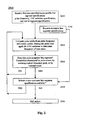
- FIG. 2 is a flow chart of an exemplary embodiment of a method 2000.
- a first user-specified line segment specification can be received and/or derived, such as from a graphical pulse frequency output profile.
- the profile can comprise a plurality of line segments, each of the line segments representing a frequency output selected from an increasing frequency output, a decreasing frequency output, and/or a constant frequency output.
- At least the first line segment can include a first or initial pulse frequency specification.
- Each line segment can comprise a plurality of user-specifiable variation characteristics, such as a magnitude of change, a rate of change, a polarity of change, a duration, and/or a length.
- One or more of the line segments can have a length specified as a number of pulses.
- One or more of the line segments can have an indefinite length terminable by a predetermined external event or reaching a predetermined frequency goal.
- an additional successor line segment specification can be received or derived.
- the additional line segment specification can include a new first frequency, a new linear-time-rate variation, and/or a new line segment termination specification.
- a pulse width can be computed from the pulse frequency.
- the user-specified linear-time-rate (“LTR") variation associated with the current line segment can be applied to determine the frequency of the next pulse .
- the LTR variation can be a change in a pulse frequency with respect to time, a change in a controlled system velocity with respect to time, a change in a pulse acceleration with respect to time, and/or a change in a controlled system acceleration with respect to time.
- a comparison can be made to determine if a target pulse frequency corresponding to a second user-specified pulse frequency has been reached.
- the second user-specified pulse frequency can be an explicitly specified frequency goal, a result of accumulating changes in frequency until a specified pulse count is reached, and/or a result of accumulating changes in frequency until an occurrence of an external event. If the target frequency has not been reached, control can return to activity 2200, and pulses can continue to be output at frequencies varying between the user-specified first pulse frequency and the second pulse frequency. If the target frequency (or end of line segment) has been reached, control can be transferred to activity 2400.
- the user-specified linear-time-rate variation can be automatically changed, such as from one line segment to a successor line segment of a pulse frequency output profile.
- the profile can be comprised of a plurality of line segments each having a length specified as terminating on reaching a number of pulses, an indefinite length that is terminated by an external event, and/or a length that is terminated by reaching a specified frequency goal. If a new successor line segment specification is available from activity 2201, this new specification can be made active and the process can resume at activity 2200. If a successor line segment has not been received at activity 2201, control can transfer to activity 2500.
- the output of pulses can be halted.
- FIG. 3 is a block diagram of an exemplary embodiment of an information device 3000, which can represent any of information devices 1100, 1300, 1600, and/or 1900, etc. of FIG. 1 .
- Information device 3000 can comprise any of numerous well-known components, such as for example, one or more network interfaces 3100, one or more processors 3200, one or more memories 3300 containing instructions 3400, one or more input/output (I/O) devices 3500, and/or one or more user interfaces 3600 coupled to I/O device 3500, etc.
- I/O input/output
- the term "information device” means any device capable of processing information , such as any general purpose and/or special purpose computer, such as a personal computer, workstation, server, minicomputer, mainframe, supercomputer, computer terminal, laptop, wearable computer, and/or Personal Digital Assistant (PDA), mobile terminal, Bluetooth device, communicator, "smart” phone (such as a Handspring Treo-like device), messaging service (e.g., Blackberry) receiver, pager, facsimile, cellular telephone, a traditional telephone, telephonic device, a programmed microprocessor or microcontroller and/or peripheral integrated circuit elements, an ASIC or other integrated circuit, a hardware electronic logic circuit such as a discrete element circuit, and/or a programmable logic device such as a PLD, PLA, FPGA, or PAL, or the like, etc.
- PDA Personal Digital Assistant
- mobile terminal such as a personal computer, workstation, server, minicomputer, mainframe, supercomputer, computer terminal, laptop, wearable computer, and/or Personal Digital Assistant (
- any device on which resides a finite state machine capable of implementing at least a portion of a method, structure, and/or or graphical user interface described herein may be used as an information device.
- An information device can include well-known components such as one or more network interfaces, one or more processors, one or more memories containing instructions, and/or one or more input/output (I/O) devices, one or more user interfaces, etc.
- network interface means any device, system, or subsystem capable of coupling an information device to a network.
- a network interface can be a telephone, cellular phone, cellular modem, telephone data modem, fax modem, wireless transceiver, ethernet card, cable modem, digital subscriber line interface, bridge, hub, router, or other similar device.
- processor means a device for processing machine-readable instruction.
- a processor can be a central processing unit, a local processor, a remote processor, parallel processors, and/or distributed processors, etc.
- the processor can be a general-purpose microprocessor, such the Pentium III series of microprocessors manufactured by the Intel Corporation of Santa Clara, California.
- the processor can be an Application Specific Integrated Circuit (ASIC) or a Field Programmable Gate Array (FPGA) that has been designed to implement in its hardware and/or firmware at least a part of an embodiment disclosed herein.
- ASIC Application Specific Integrated Circuit
- FPGA Field Programmable Gate Array
- a "memory device” means any hardware element capable of data storage, such as for example, a non-volatile memory, volatile memory, Random Access Memory, RAM, Read Only Memory, ROM, flash memory, magnetic media, a hard disk, a floppy disk, a magnetic tape, an optical media, an optical disk, a compact disk, a CD, a digital versatile disk, a DVD, and/or a raid array, etc.
- firmware means machine-readable instructions that are stored in a read-only memory (ROM).
- ROM's can comprise PROMs and EPROMs.
- I/O device means any sensory-oriented input and/or output device, such as an audio, visual, haptic, olfactory, and/or taste-oriented device, including, for example, a monitor, display, projector, overhead display, keyboard, keypad, mouse, trackball, joystick, gamepad, wheel, touchpad, touch panel, pointing device, microphone, speaker, video camera, camera, scanner, printer, haptic device, vibrator, tactile simulator, and/or tactile pad, potentially including a port to which an I/O device can be attached or connected.
- an audio, visual, haptic, olfactory, and/or taste-oriented device including, for example, a monitor, display, projector, overhead display, keyboard, keypad, mouse, trackball, joystick, gamepad, wheel, touchpad, touch panel, pointing device, microphone, speaker, video camera, camera, scanner, printer, haptic device, vibrator, tactile simulator, and/or tactile pad, potentially including a port to which an I/O device can be attached or connected.
- haptic means both the human sense of kinesthetic movement and the human sense of touch.
- many potential haptic experiences are numerous sensations, body-positional differences in sensations, and time-based changes in sensations that are perceived at least partially in non-visual, non-audible, and non-olfactory manners, including the experiences of tactile touch (being touched), active touch, grasping, pressure, friction, traction, slip, stretch, force, torque, impact, puncture, vibration, motion, acceleration, jerk, pulse, orientation, limb position, gravity, texture, gap, recess, viscosity, pain, itch, moisture, temperature, thermal conductivity, and thermal capacity.
- a user interface means any device for rendering information to a user and/or requesting information from the user.
- a user interface includes at least one of textual, graphical, audio, video, animation, and/or haptic elements.
- a textual element can be provided, for example, by a printer, monitor, display, projector, etc.
- a graphical element can be provided, for example, via a monitor, display, projector, and/or visual indication device, such as a light, flag, beacon, etc.
- An audio element can be provided, for example, via a speaker, microphone, and/or other sound generating and/or receiving device.
- a video element or animation element can be provided, for example, via a monitor, display, projector, and/or other visual device.
- a haptic element can be provided, for example, via a very low frequency speaker, vibrator, tactile stimulator, tactile pad, simulator, keyboard, keypad, mouse, trackball, joystick, gamepad, wheel, touchpad, touch panel, pointing device, and/or other haptic device, etc.
- a user interface can include one or more textual elements such as, for example, one or more letters, number, symbols, etc.
- a user interface can include one or more graphical elements such as, for example, an image, photograph, drawing, icon, window, title bar, panel, sheet, tab, drawer, matrix, table, form, calendar, outline view, frame, dialog box, static text, text box, list, pick list, pop-up list, pull-down list, menu, tool bar, dock, check box, radio button, hyperlink, browser, button, control, palette, preview panel, color wheel, dial, slider, scroll bar, cursor, status bar, stepper, and/or progress indicator, etc.
- a textual and/or graphical element can be used for selecting, programming, adjusting, changing, specifying, etc.
- a user interface can include one or more audio elements such as, for example, a volume control, pitch control, speed control, voice selector, and/or one or more elements for controlling audio play, speed, pause, fast forward, reverse, etc.
- a user interface can include one or more video elements such as, for example, elements controlling video play, speed, pause, fast forward, reverse, zoom-in, zoom-out, rotate, and/or tilt, etc.
- a user interface can include one or more animation elements such as, for example, elements controlling animation play, pause, fast forward, reverse, zoom-in, zoom-out, rotate, tilt, color, intensity, speed, frequency, appearance, etc.
- a user interface can include one or more haptic elements such as, for example, elements utilizing tactile stimulus, force, pressure, vibration, motion, displacement, temperature, etc.
- a user via one or more user interfaces 3600, such as a graphical user interface, a user can provide a desired motion profile.
- FIG. 4 is a diagram of an exemplary typical desired motion profile 4000, described in terms of desired pulse frequency versus time.
- Such profiles can be used in industry to describe, for example, the speed of a motor positioning a tool, where the frequency of pulses delivered to the motor system controls the rotational speed.
- Typical motor systems used in industry today have scaling factors of from 200 to 200000 pulses per revolution.
- Typical acceleration times from minimum to maximum frequency can range from a few milliseconds up to many seconds.
- the actual object of the motion is often to move a specific distance, expressed as a specific number of pulses, while satisfying constraints on acceleration, and change in acceleration.
- Controlled changes in acceleration represented by the curved portions of the illustrative profile, might or might not be included in a particular application, but are increasingly valued as users strive for higher speed movement without introducing disruptive jerks.
- the motion represented by the profile in Fig. 4 can start and stop with abrupt changes between 0 and some minimum finite frequency. This can be minimally required by the nature of the system, since frequency can be expressed as a series of finite width pulses. Further, typical motors have minimum start and stop speeds of, for example, 5% or 10% of maximum rated speed, below which minimums the motor might stall or operate erratically. After the initial step to the minimum start frequency, acceleration can be smoothly increased to some maximum amount, then can be smoothly decreased to zero to achieve a constant speed at the top of the profile, followed by a similar reverse process to smoothly slow down to minimum speed and stop. As used herein, a factor df means a change in frequency per unit time, and a factor ddf describes a change in df per unit time. That is, df represents an acceleration and ddf a rate of change in acceleration.
- regimes 4100-4900 which can be comprised of one or more line segments, and which can be described as follows:
- Line segment Parameters of each line segment can be independently specified or maintained from a previous segment. This example is deliberately asymmetrical to illustrate flexibility of line segment description.
- the number of line segments can be indefinitely extensible, and can loaded from some external storage.
- the term "line segment" means a portion of the curve, whether or not straight, controlled by a single load from the pipeline registers.
- Fig. 4 represents a simple motion profile of start, speed up to some constant frequency, slow down, and stop
- Such profiles might include multiple intervals of constant speed, connected by intervening accelerations of different magnitudes, and perhaps including segments that are indefinitely extended, requiring some external signal or external data input to the system to determine the timing and nature of a next step.
- Parameters for each segment of the profile can be independently,specified, or maintained from the previous segment, allowing for considerable flexibility in application.
- FIG. 5 is a block diagram of an exemplary embodiment of a system 5000, which can include a number of components.
- start-frequency (sf) variable 5110 can be utilized to determine a working frequency (wf) variable 5210.
- a delta frequency pipeline (dfh) variable 5120 can be used to determine a delta_frequency (df) variable 5220.
- a delta delta frequency pipeline (ddfh) variable 5130 can be used to determine a delta delta_frequency (ddf) variable 5230.
- a compare pipeline (cmprh) variable 5140 can be used to determine a compare (cmpr) variable 5430.
- Control and/or status flags 5150 can control the operation of a state machine 5440.
- Adder 5310 can provide a new value to working frequency (wf) variable 5210 and/or input to compare variable 5430.
- Adder 5320 can provide a new value to delta frequency (df) variable 5220.
- Interval timer 5330 can provide input to state machine 5440 to control the rate at which adder 5310 and adder 5320 operations are applied.
- Divider 5410 can receive input from working frequency variable 5210 and/or source frequency 5420 and can output a pulse width variable 5510 which can flow to a pulse width counter . 5610.
- any of the following features can be provided:
- a pulse train generation function can be included in an integrated circuit with a general purpose processor, general purpose communications circuits, a programmable high speed counter for counting pulses produced by the pulse train generation function, and/or other specialty circuits convenient to the embodiment of a programmable logic controller.
- the output of the pulse generation function can be coupled to a discrete output of the programmable logic controller, which can be a transistor, opto-coupled transistor, relay, and/or other switching device that delivers the pulses as electrical signals appropriate to various end receivers.
- the linear ramp Pulse Train Output (Ipto) system can allow specification of the pulse train in terms of frequency and change in frequency per unit time.
- the modes of operation can be as follows :
- run_steps_n run for a specified number of pulses, starting from a specified frequency and changing the frequency at a specified rate per unit time. At the completion of the pulse count, load a new step specification.
- run_steps_f run until a specified frequency target is reached, starting from a specified frequency and changing the frequency at a specified rate per unit time. On achieving the specified frequency, load a new step specification.
- run_continuous run at constant frequency for an indefinite time
- abort state is entered due to an abort command or certain error events.
- Abort mode halts any frequency change in progress, and disables pipeline loads or state transitions. Reliable set up for a graceful shut-down is possible, or the unit can simply be commanded to stop.
- last_step_n run for a specified number of pulses, starting from a specified frequency and changing the frequency at a specified rate per unit time. Stop at the completion of the pulse count.
- last_step_f run until a specified frequency target is reached, starting from a specified frequency and changing the frequency at a specified rate per unit time. On achieving the specified frequency stop.
- the data registers that specify the operation are :
- start frequency (sf) The first frequency value that will be used to generate a pulse width specification.
- source frequency src_f
- output pulse width in system clocks integer(src_f / wf).
- delta frequency (df) This is stored as a composite value, including a magnitude value to add to the working frequency, and a rate value, specifying the interval at which the addition takes place. This register is accessed by firmware by loading the dfh (delta frequency pipeline).
- a wide range of interval selections allows a fixed point calculation of wf+df_magnitude to cover a very wide range of desired frequency slopes.
- delta change in frequency (ddf) : Same format as the magnitude and sign portion of the df register, and accessed by firmware by loading the ddfh (delta delta_frequency pipeline).
- the signed addition df ⁇ df+ ddf , repeated at regular counted clock intervals, provides for linear changes in acceleration with respect to time.
- the df and ddf registers are updated on the same schedule. An alternate schedule for the ddf register update is also possible.
- this register counts the pulses.
- this register contains the value of the desired end point frequency. This register is accessed by firmware by loading the cmprh (compare register pipeline).
- pulse width (pw) read for diagnostic use only, contains the currently used value of pulse width in system clocks.
- abort Firmware command to enter abort mode, holding frequency constant and blocking pipeline loads. In the case of an add_error, firmware sets this bit to acknowledge awareness of the add_error and that the lpto has entered abort mode automatically.
- run_ack state machine acknowledgement that the lpto is running.
- abort_ack state machine acknowledgement that the lpto has observed the abort bit assertion and is in the abort mode.
- active_pulse indicator that a pulse is committed or in progress, primarily useful at the end of sequence where the negation of active_pulse indicates the sequence is complete.
- pipe_loaded indicates that some pipe register (sf, dfh, cmprh) is loaded. Negation of pipe_loaded signals the firmware that new information is required to continue the linear pto sequence.
- add_error indicates that the lpto has encountered some condition that makes further automatic changes in the frequency problematic.
- the generic term add error includes all mathematical errors, data format errors, and pipeline status errors that may be detected and reported. On add_error, the lpto enters the abort mode automatically.
- transfer pipeline command (xfr_pipe) : A write to the xfr_pipe address causes the lpto state machine to load the frequency divider and get ready to make the first pulse of a new sequence. Used to start the machine from idle or pick up a new specification to leave run_continuous state.
- src_f the frequency of the system clock available to measure pulse width as a number of counted clocks.
- src_f is presumed to remain constant for a complete motion, src_f may be fixed for a system or provided as some selectable clock source.
- Processor loads the remaining data pipeline registers, wfh, dfh, ddfh, and cmprh as desired, and writes a xfr_pipeline command to load the working registers wf, df, ddf, cmpr.
- the pipeline registers are now written with a second set of values to be ready for the next line segment.
- the initial working frequency specification, wf is loaded to the divider.
- the divider determines a first pulse width specification by dividing src_f / wf.
- the division result is loaded to a buffered pulse width specification register, pw.
- the pulse width counter obtains the value of pw, and begins producing pulses by counting clocks. Each output pulse is high for approximately one-half the specified pw count, and low for the remainder of the pw count. At the completion of each pw count, a new value of the buffered pw from the divider is fetched and another pulse width is counted out.
- an interval timer is marking update events as specified by the time specification portion of the df register.
- wf is loaded with a new value of wf + df
- df is loaded with a new value of df + ddf.
- the latest value of pw is available to the pulse width counter to use for timing the next pulse on each pulse boundary. Note that pulse widths are changing throughout a sequence, while the update interval is fixed. New values of pw may be presented at any time during a pulse, and may be replaced by yet new values before the next pulse start requires a new pw. Synchronous machinery assures that only valid values of pw are transferred to the pulse width counter.
- the processor commanding an abort, an error escape from any mode.
- the pulse width counter is commanded to stop issuing pulses on the completion of a pulse, and the processor is notified of process completion. Additional line segments, with possible changes in mode carried in their specifications, may be loaded indefinitely.
- a xfr_pipetine command during run_continuous mode causes new line segment specifications to be loaded, which may include a change in mode. Typically this would be a run_steps_f line segment to transition to a new speed or a last_step_f segment to decelerate to a smooth stop. Additional line segments, with possible changes in mode carried in their specifications, may be loaded indefinitely.
- An abort command may be initiated as a response to internal errors (e.g. an illegal result in a math operation), or external events (e.g., an unexpected shut down request in the larger programmable logic control system).
- the abort command stops operation of the update interval timer, the divider, and pipeline loads, readying the system to be set up for a new line segment.
- the pulse width counter continues to issue pulses at the last pw value specified, maintaining the external motor or other target device at a constant speed.
- the processor may command an immediate stop, or, more typically, load a new line segment specification in the pipe line registers and execute a xfr_pipeline command to initiate the new segment.
- the new line segment might be a smooth transition to a new operating point or a smooth deceleration to stop.
Landscapes
- Engineering & Computer Science (AREA)
- Physics & Mathematics (AREA)
- General Physics & Mathematics (AREA)
- Automation & Control Theory (AREA)
- Power Engineering (AREA)
- Human Computer Interaction (AREA)
- Manufacturing & Machinery (AREA)
- Programmable Controllers (AREA)
- Networks Using Active Elements (AREA)
- Stabilization Of Oscillater, Synchronisation, Frequency Synthesizers (AREA)
Claims (40)
- Verfahren zum Erzeugen von Pulsausgängen aus einer speicherprogrammierbaren Steuerung (PLC), welches folgendes umfasst:automatisches Ändern einer ersten vom Benutzer spezifizierten Pulsfrequenz in eine zweite Pulsfrequenz; undautomatisches Ausgeben einer Mehrzahl von Pulsen aus der speicherprogrammierbaren Steuerung (PLC) mit Frequenzen, die entsprechend einer vom Benutzer spezifizierten linearen Zeit/Geschwindigkeit-Änderung zwischen der ersten vom Benutzer spezifizierten Pulsfrequenz und der zweiten Pulsfrequenz variieren, dadurch gekennzeichnet, dass die vom Benutzer spezifizierte lineare Zeit/Geschwindigkeit-Änderung von einem Pulsfrequenz-Ausgangsprofil empfangen wird, das eine Mehrzahl von Liniensegmenten umfasst, wobei mindestens eines dieser Liniensegmente eine unbestimmte Länge hat, die durch ein vorab festgelegtes externes Ereignis oder durch Erreichen eines vorab festgelegten Frequenzziels beendet werden kann.
- Verfahren gemäß Anspruch 1, wobei die vom Benutzer spezifizierte lineare Zeit/Geschwindigkeit-Änderung eine Änderung der Pulsfrequenz in Bezug auf die Zeit ist.
- Verfahren gemäß Anspruch 1, wobei die vom Benutzer spezifizierte lineare Zeit/Geschwindigkeit-Änderung eine Änderung einer kontrollierten Systemgeschwindigkeit in Bezug auf die Zeit ist.
- Verfahren gemäß Anspruch 1, wobei die vom Benutzer spezifizierte lineare Zeit/Geschwindigkeit-Änderung eine Änderung einer Pulsbeschleunigung in Bezug auf die Zeit ist.
- Verfahren gemäß Anspruch 1, wobei die vom Benutzer spezifizierte lineare Zeit/Geschwindigkeit-Änderung eine Änderung einer kontrollierten Systembeschleunigung in Bezug auf die Zeit ist.
- Verfahren gemäß Anspruch 1, welches ferner folgendes umfasst:Empfangen eines Signals, das die vom Benutzer spezifizierte lineare Zeit/Geschwindigkeit-Änderung anzeigt.
- Verfahren gemäß Anspruch 1, welches ferner folgendes umfasst:Berechnen einer Mehrzahl von Pulsfrequenzen entsprechend der vom Benutzer spezifizierten linearen Zeit/Geschwindigkeit-Änderung zwischen der ersten vom Benutzer spezifizierten Pulsfrequenz und der zweiten Pulsfrequenz.
- Verfahren gemäß Anspruch 1, welches ferner folgendes umfasst:Berechnen einer Mehrzahl von Pulsbeschleunigungen entsprechend der vom Benutzer spezifizierten linearen Zeit/Geschwindigkeit-Änderung zwischen der ersten vom Benutzer spezifizierten Pulsfrequenz und der zweiten Pulsfrequenz.
- Verfahren gemäß Anspruch 1, welches ferner folgendes umfasst:Berechnen einer Zielpulsfrequenz entsprechend der zweiten Pulsfrequenz, wobei die zweite Pulsfrequenz vom Benutzer spezifiziert ist.
- Verfahren gemäß Anspruch 1, welches ferner folgendes umfasst:Berechnen einer Zielpulsfrequenz entsprechend der zweiten Pulsfrequenz, wobei die zweite Pulsfrequenz nicht vom Benutzer spezifiziert ist.
- Verfahren gemäß Anspruch 1, welches ferner folgendes umfasst:Berechnen einer Zielpulsbeschleunigung entsprechend der vom Benutzer spezifizierten linearen Zeit/Geschwindigkeit-Änderung.
- Verfahren gemäß Anspruch 1, wobei die vom Benutzer spezifizierte lineare Zeit/Geschwindigkeit-Änderung von einem grafischen Pulsfrequenz-Ausgangsprofil empfangen wird.
- Verfahren gemäß Anspruch 1, wobei die vom Benutzer spezifizierte lineare Zeit/Geschwindigkeit-Änderung von einem grafischen Pulsfrequenz-Ausgangsprofil abgeleitet wird.
- Verfahren gemäß Anspruch 1, wobei die von Benutzer spezifizierte lineare Zeit/Geschwindigkeit-Änderung von einem Pulsfrequenz-Ausgangsprofil empfangen wird, das eine Mehrzahl von Liniensegmenten umfasst, wobei jedes dieser Liniensegmente einen Frequenzausgang repräsentiert, der aus einem ansteigenden Frequenzausgang, einem absteigenden Frequenzausgang und einem konstanten Frequenzausgang ausgewählt ist.
- Verfahren gemäß Anspruch 1, wobei die von Benutzer spezifizierte lineare Zeit/Geschwindigkeit-Änderung von einem Pulsfrequenz-Ausgangsprofil empfangen wird, das eine Mehrzahl von Liniensegmenten umfasst, wobei jedes dieser Liniensegmente eine Mehrzahl von benutzerdefinierbaren Änderungsmerkmalen umfasst.
- Verfahren gemäß Anspruch 1, wobei die von Benutzer spezifizierte lineare Zeit/Geschwindigkeit-Änderung von einem Pulsfrequenz-Ausgangsprofil empfangen wird, das eine Mehrzahl von Liniensegmenten umfasst, wobei jedes dieser Liniensegmente vom Benutzer spezifizierbare Eigenschaften umfasst, die ausgewählt sind aus einer Größe der Änderung, einer Geschwindigkeit der Änderung, einer Polarität der Änderung, einer Dauer und einer Länge.
- Verfahren gemäß Anspruch 1, wobei die von Benutzer spezifizierte lineare Zeit/Geschwindigkeit-Änderung von einem Pulsfrequenz-Ausgangsprofil empfangen wird, das eine Mehrzahl von Liniensegmenten umfasst, wobei für mindestens eines der Liniensegmente eine Länge als eine Anzahl von Pulsen spezifiziert ist.
- Verfahren gemäß Anspruch 1, welches ferner folgendes umfasst:abruptes Beenden der Mehrzahl von Pulsen.
- Verfahren gemäß Anspruch 1, welches ferner folgendes umfasst:automatisches Ändern der vom Benutzer spezifizierten linearen Zeit/Geschwindigkeit-Änderung von einem Liniensegment auf ein nachfolgendes Liniensegment eines Pulsfrequenz-Ausgangsprofils, das eine Mehrzahl von Liniensegmenten umfasst, die jeweils eine Länge haben, welche als Anzahl von Pulsen spezifiziert ist, die eine unbestimmte Länge haben, welche durch ein externes Ereignis beendet wird, oder eine Länge haben, welche durch Erreichen eines spezifizierten Frequenzziels beendet wird.
- Verfahren gemäß Anspruch 1, wobei die zweite Pulsfrequenz ein Ergebnis des Akkumulierens von Änderungen der Frequenz bis zum Erreichen einer spezifizierten Anzahl von Pulsen ist.
- Verfahren gemäß Anspruch 1, wobei die zweite Pulsfrequenz ein Ergebnis des Akkumulierens von Änderungen der Frequenz bis zum Eintreten eines externen Ereignisses ist.
- Verfahren gemäß Anspruch 1, wobei die zweite Pulsfrequenz ein explizit spezifiziertes Frequenzziel ist.
- Maschinenlesbarer Datenträger, der Instruktionen für eine speicherprogrammierbare Steuerung (PLC) enthält, um ein Verfahren gemäß einem der vorstehenden Ansprüche durchzuführen, wenn die Instruktionen in der speicherprogrammierbaren Steuerung ausgeführt werden.
- System zum Erzeugen von Pulsausgängen, welches folgendes umfasst:einen Pulsgenerator, der dafür ausgelegt ist, lineare Änderungen der Frequenz in Bezug auf die Zeit zu erzeugen, indem er in regelmäßigen spezifizierten Intervallen ein spezifiziertes Frequenzinkrement zu einer spezifizierten Frequenz addiert bzw. von dieser subtrahiert, um eine Frequenzspezifikation zu erzeugen,einen Dividierermechanismus, der dafür ausgelegt ist, die Frequenzspezifikation in eine Pulsbreitenspezifikation umzuwandeln,einen Pulsbreitengenerator, der einen gewünschten Pulsausgang erzeugt, indem er Takte einer fixen Referenzfrequenz gemäß der Pulsbreitenspezifikation zählt, gekennzeichnet durch eine Mehrzahl von Pipeline-Datenregistern und einen steuernden Zustandsautomaten, wobei die besagten Pipeline-Datenregister und der besagte Zustandsautomat dafür ausgelegt sind, eine planmäßige automatische Änderung von einer ersten Pulsausgabespezifikation auf eine zweite Pulsausgabespezifikation bereitzustellen, wobei eine Dauer der ersten Pulsausgabespezifikation unbestimmt ausgedehnt ist bis zum Eintreten eines externen Ereignisses.
- System nach Anspruch 24, wobei der besagte Pulsgenerator dafür ausgelegt ist, lineare Änderungen der Beschleunigung in Bezug auf die Zeit zu erzeugen, indem er ein spezifiziertes Beschleunigungsinkrement zu dem spezifizierten Frequenzinkrement addiert bzw. von diesem subtrahiert.
- System gemäß Anspruch 24, ferner umfassend eine Mehrzahl von Pipeline-Datenregistern und einen steuernden Zustandsautomaten, wobei die besagten Pipeline-Datenregister und der besagte steuernde Zustandsautomat dafür ausgelegt sind, eine planmäßige automatische Änderung von einer Spezifikation einer ersten Pulsausgabe zu einer zweiten Pulsausgabespezifikation bereitzustellen, sobald eine spezifizierte Anzahl von Pulsen für die erste Pulsausgabe abgeschlossen ist.
- System gemäß Anspruch 24, ferner umfassend eine Mehrzahl von Pipeline-Datenregistern und einen steuernden Zustandsautomaten, wobei die besagten Pipeline-Datenregister und der besagte steuernde Zustandsautomat dafür ausgelegt sind, eine planmäßige automatische Änderung von einer Spezifikation einer ersten Pulsausgabe zu einer zweiten Pulsausgabespezifikation bereitzustellen, sobald ein spezifiziertes Frequenzziel für die erste Pulsausgabe erreicht ist.
- System gemäß Anspruch 24, ferner umfassend eine Mehrzahl von Pipeline-Datenregistern und einen steuernden Zustandsautomaten, wobei die besagten Pipeline-Datenregister und der besagte steuernde Zustandsautomat dafür ausgelegt sind, die Ausführung einer laufenden Pulsausgabespezifikation abzubrechen.
- System gemäß Anspruch 24, ferner umfassend eine Mehrzahl von Pipeline-Datenregistern und einen steuernden Zustandsautomaten, wobei die besagten Pipeline-Datenregister und der besagte steuernde Zustandsautomat dafür ausgelegt sind, eine planmäßige automatische Änderung von einer ersten Pulsausgabespezifikation zu einer zweiten Pulsausgabespezifikation zu blockieren.
- System nach Anspruch 24, ferner umfassend eine Mehrzahl von Pipeline-Datenregistern und einen steuernden Zustandsautomaten, der einen "abort"-Zustand umfasst, in dem eine Aktion eines ersten aktuell ausgeführten Liniensegments unterbrochen wird, indem weitere Änderungen der Frequenz und Beschleunigung ausgesetzt werden und eine planmäßige automatische Änderung von einer Spezifikation des ersten aktuell ausgeführten Liniensegments auf eine Spezifikation eines zweiten geplanten Liniensegments ausgesetzt wird, und die Beibehaltung einer stationären Pulsfolge zugelassen wird, während eine neue Spezifikation an die Stelle des zweiten geplanten Liniensegments gesetzt wird, wobei der Übergang in den "abort"-Zustand durch einen externen Befehl, durch Erkennung eines einsetzenden mathematischen Fehlers oder durch Erkennen von unvollständigen Spezifikationsdaten im Zusammenhang mit dem zweiten geplanten Liniensegment erfolgt.
- System nach Anspruch 24, ferner umfassend einen Aktualisierungsintervallzähler und ein codiertes spezifiziertes Intervall.
- System nach Anspruch 24, ferner umfassend einen Aktualisierungsintervallzähler und ein codiertes spezifiziertes Intervall, wobei eine Dauer des regelmäßigen spezifizierten Intervalls eine Wiederholung der inkrementellen Additionen zu Frequenz und Beschleunigung steuert.
- System nach Anspruch 24, ferner umfassend ein Anhalteelement, das dafür ausgelegt ist, die Pulsausgabe exakt bei Beendigung einer finalen Spezifikation anzuhalten.
- System nach Anspruch 24, ferner umfassend einen Zähler, der dafür ausgelegt ist, die absolute und die relative Position über eine unbestimmt ausgedehnte Sequenz von kontrollierten Frequenzpulsfolge-Operationen zu überwachen.
- System nach Anspruch 24, ferner umfassend einen Zähler, der dafür ausgelegt ist, die Anzahl Pulse über eine unbestimmt ausgedehnte Sequenz von kontrollierten Frequenzpulsfolge-Operationen zu überwachen.
- System nach Anspruch 24, ferner umfassend eine wählbare Takteingangsfrequenz.
- System nach Anspruch 24, wobei das besagte System in einer integrierten Schaltung implementiert ist.
- System nach Anspruch 24, wobei das besagte System in einer speicherprogrammierbaren Steuerung (PLC) implementiert ist.
- System nach Anspruch 24, wobei das besagte System in einem Informationsverarbeitungsgerät implementiert ist, welches eine Netzwerkschnittstelle umfasst.
- System nach Anspruch 24, wobei das besagte System in einem Informationsverarbeitungsgerät implementiert ist, welches eine Internet-Schnittstelle umfasst.
Applications Claiming Priority (5)
| Application Number | Priority Date | Filing Date | Title |
|---|---|---|---|
| US45021003P | 2003-02-26 | 2003-02-26 | |
| US450210P | 2003-02-26 | ||
| US10/770,663 US7171578B2 (en) | 2003-02-26 | 2004-02-03 | Pulse output function for programmable logic controller with linear frequency change |
| US770663 | 2004-02-03 | ||
| PCT/US2004/005681 WO2004077176A2 (en) | 2003-02-26 | 2004-02-26 | Pulse output function for programmable logic controller with linear frequency change |
Publications (2)
| Publication Number | Publication Date |
|---|---|
| EP1597642A2 EP1597642A2 (de) | 2005-11-23 |
| EP1597642B1 true EP1597642B1 (de) | 2009-08-26 |
Family
ID=32930546
Family Applications (1)
| Application Number | Title | Priority Date | Filing Date |
|---|---|---|---|
| EP04715031A Expired - Lifetime EP1597642B1 (de) | 2003-02-26 | 2004-02-26 | Pulsausgabefunktion mit linearer frequenzänderung für eine speicherprogrammierbare steuerung |
Country Status (8)
| Country | Link |
|---|---|
| US (1) | US7171578B2 (de) |
| EP (1) | EP1597642B1 (de) |
| CN (1) | CN102393674B (de) |
| AT (1) | ATE441138T1 (de) |
| CA (1) | CA2516650C (de) |
| DE (1) | DE602004022780D1 (de) |
| ES (1) | ES2329575T3 (de) |
| WO (1) | WO2004077176A2 (de) |
Families Citing this family (18)
| Publication number | Priority date | Publication date | Assignee | Title |
|---|---|---|---|---|
| US8040100B2 (en) * | 2008-06-16 | 2011-10-18 | International Business Machines Corporation | Automatically determining optimal pulse duration for a stepper motor |
| US8760273B2 (en) * | 2008-12-16 | 2014-06-24 | Dell Products, Lp | Apparatus and methods for mounting haptics actuation circuitry in keyboards |
| US8711011B2 (en) * | 2008-12-16 | 2014-04-29 | Dell Products, Lp | Systems and methods for implementing pressure sensitive keyboards |
| US9246487B2 (en) | 2008-12-16 | 2016-01-26 | Dell Products Lp | Keyboard with user configurable granularity scales for pressure sensitive keys |
| US8674941B2 (en) * | 2008-12-16 | 2014-03-18 | Dell Products, Lp | Systems and methods for implementing haptics for pressure sensitive keyboards |
| US20100249952A1 (en) * | 2009-03-31 | 2010-09-30 | Schneider Electric/Square D Company | Direct Control of Devices Through a Programmable Controller Using Internet Protocol |
| CN101860123B (zh) * | 2009-04-13 | 2012-03-21 | 中山大洋电机股份有限公司 | 一种电机 |
| DE202011100573U1 (de) * | 2011-05-12 | 2012-08-13 | Grass Gmbh | Vorrichtung zum Bewegen eines bewegbaren Möbelteils und Möbel |
| US8700829B2 (en) | 2011-09-14 | 2014-04-15 | Dell Products, Lp | Systems and methods for implementing a multi-function mode for pressure sensitive sensors and keyboards |
| US9343248B2 (en) | 2013-08-29 | 2016-05-17 | Dell Products Lp | Systems and methods for implementing spring loaded mechanical key switches with variable displacement sensing |
| US9368300B2 (en) | 2013-08-29 | 2016-06-14 | Dell Products Lp | Systems and methods for lighting spring loaded mechanical key switches |
| US9111005B1 (en) | 2014-03-13 | 2015-08-18 | Dell Products Lp | Systems and methods for configuring and controlling variable pressure and variable displacement sensor operations for information handling systems |
| CN103885381B (zh) * | 2014-03-18 | 2016-09-07 | 深圳市汇川控制技术有限公司 | 一种宽压plc输入电路 |
| US9106216B1 (en) * | 2014-07-31 | 2015-08-11 | Microsoft Technology Licensing Llc | Programmable pulse generation |
| CN111522289B (zh) * | 2020-04-03 | 2021-08-10 | 北京齐乐无穷文化科技有限公司 | 基于plc的伺服运动控制系统、方法及vr设备 |
| CN111437595B (zh) | 2020-04-23 | 2022-11-15 | 腾讯科技(深圳)有限公司 | 滑觉模拟装置、被控机器人和游戏手柄 |
| CN113705768B (zh) * | 2020-05-22 | 2025-08-12 | 北京灵汐科技有限公司 | 一种频率编码脉冲数据的生成方法和装置 |
| CN111711751B (zh) * | 2020-06-16 | 2021-03-12 | 南京认知物联网研究院有限公司 | 基于plc脉冲信号的拍照控制及处理照片的方法、系统和设备 |
Family Cites Families (9)
| Publication number | Priority date | Publication date | Assignee | Title |
|---|---|---|---|---|
| US4103216A (en) * | 1976-05-28 | 1978-07-25 | Tally Corporation | Stepping motor closed loop constant velocity control system |
| JPH07194193A (ja) * | 1993-12-27 | 1995-07-28 | Canon Inc | モータ制御方法 |
| DE4417424A1 (de) | 1994-05-18 | 1995-11-23 | Siemens Ag | Steuerung für einen Schrittantrieb |
| DE19501652C2 (de) | 1995-01-18 | 1998-06-04 | Siemens Ag | Verfahren und Einrichtung zur Generierung von Frequenzrampen |
| JP3023648B2 (ja) * | 1995-06-05 | 2000-03-21 | ファナック株式会社 | 位置制御装置 |
| JPH1169886A (ja) * | 1997-08-20 | 1999-03-09 | Nippon Parusumootaa Kk | ステッピングモータ等の駆動制御集積回路及びその駆動制御集積回路を備えたステッピングモータ |
| JP3817920B2 (ja) * | 1998-08-26 | 2006-09-06 | 松下電工株式会社 | 加減速制御回路 |
| US6717383B1 (en) * | 2000-08-30 | 2004-04-06 | Chris S. Brunt | Fountain control for generating dynamically changing flow patterns |
| JP4174972B2 (ja) * | 2001-02-09 | 2008-11-05 | 三菱電機株式会社 | 位置決め制御方法 |
-
2004
- 2004-02-03 US US10/770,663 patent/US7171578B2/en not_active Expired - Fee Related
- 2004-02-26 WO PCT/US2004/005681 patent/WO2004077176A2/en not_active Ceased
- 2004-02-26 EP EP04715031A patent/EP1597642B1/de not_active Expired - Lifetime
- 2004-02-26 ES ES04715031T patent/ES2329575T3/es not_active Expired - Lifetime
- 2004-02-26 CN CN201110389608.4A patent/CN102393674B/zh not_active Expired - Fee Related
- 2004-02-26 CA CA002516650A patent/CA2516650C/en not_active Expired - Fee Related
- 2004-02-26 AT AT04715031T patent/ATE441138T1/de active
- 2004-02-26 DE DE602004022780T patent/DE602004022780D1/de not_active Expired - Lifetime
Also Published As
| Publication number | Publication date |
|---|---|
| CA2516650C (en) | 2008-09-30 |
| WO2004077176A3 (en) | 2005-03-03 |
| US20040174200A1 (en) | 2004-09-09 |
| CN102393674A (zh) | 2012-03-28 |
| WO2004077176A2 (en) | 2004-09-10 |
| DE602004022780D1 (de) | 2009-10-08 |
| CA2516650A1 (en) | 2004-09-10 |
| ATE441138T1 (de) | 2009-09-15 |
| CN102393674B (zh) | 2014-06-11 |
| EP1597642A2 (de) | 2005-11-23 |
| US7171578B2 (en) | 2007-01-30 |
| ES2329575T3 (es) | 2009-11-27 |
Similar Documents
| Publication | Publication Date | Title |
|---|---|---|
| EP1597642B1 (de) | Pulsausgabefunktion mit linearer frequenzänderung für eine speicherprogrammierbare steuerung | |
| CA2472018C (en) | Pulse output function for programmable logic controller | |
| US4134106A (en) | Absolute resolver angle to digital converter circuit | |
| EP1959323B1 (de) | Eliminierung unbeabsichtigter Geschwindigkeitsumwandlungen in S-Kurven-Geschwindigkeitsprofilen | |
| EP3904998A1 (de) | Vorrichtung zur synchronen steuerung, system zur synchronen steuerung, verfahren zur synchronen steuerung und simulationsvorrichtung | |
| CN102097991B (zh) | 步进电动机驱动装置及驱动方法 | |
| JPS62192803A (ja) | 原点復帰方法 | |
| JP2003532904A (ja) | 高分解能位置センサ装置及び方法 | |
| CN100498610C (zh) | 一种对定位对象进行定位的方法和装置 | |
| Gong et al. | LabVIEW-base automatic rising and falling speed control of stepper motor | |
| CN118282262B (zh) | 一种步进电机的控制方法、控制系统、电子设备及存储介质 | |
| CN101349907A (zh) | 一种数控系统及其数据流优化方法 | |
| CN110262386A (zh) | 一种连续运转冷床的控制方法、系统以及计算机设备 | |
| CN1781063A (zh) | 具有线性频率变化的可编程逻辑控制器的脉冲输出功能 | |
| JP4194836B2 (ja) | インクリメンタルセンサ・シミュレーションとして、複数の電気パルスを数値設定に基づき自動的に形成する方法 | |
| KR930001582B1 (ko) | 원점 복귀방법 | |
| CN111162703B (zh) | 步进电机控制方法、装置及存储介质 | |
| Lewin | Mathematics of motion control profiles | |
| CN101369131B (zh) | 用于产生可变频率脉冲的方法、装置和系统 | |
| CN111614301A (zh) | 马达编码器的动态采样方法 | |
| Zeqiri | Functional parameters and performance requirement in the industrial system | |
| CN104635625A (zh) | 基于ip核的运动控制方法及装置 | |
| JP6773072B2 (ja) | 制御装置、システムおよび制御方法 | |
| KR100405718B1 (ko) | 위치제어를 위한 원호 보간 방법 및 시스템 | |
| CN118131827A (zh) | 一种自适应的伺服电机追切控制方法、装置及系统 |
Legal Events
| Date | Code | Title | Description |
|---|---|---|---|
| PUAI | Public reference made under article 153(3) epc to a published international application that has entered the european phase |
Free format text: ORIGINAL CODE: 0009012 |
|
| 17P | Request for examination filed |
Effective date: 20050818 |
|
| AK | Designated contracting states |
Kind code of ref document: A2 Designated state(s): AT BE BG CH CY CZ DE DK EE ES FI FR GB GR HU IE IT LI LU MC NL PT RO SE SI SK TR |
|
| AX | Request for extension of the european patent |
Extension state: AL LT LV MK |
|
| DAX | Request for extension of the european patent (deleted) | ||
| 17Q | First examination report despatched |
Effective date: 20080220 |
|
| GRAP | Despatch of communication of intention to grant a patent |
Free format text: ORIGINAL CODE: EPIDOSNIGR1 |
|
| GRAS | Grant fee paid |
Free format text: ORIGINAL CODE: EPIDOSNIGR3 |
|
| GRAA | (expected) grant |
Free format text: ORIGINAL CODE: 0009210 |
|
| AK | Designated contracting states |
Kind code of ref document: B1 Designated state(s): AT BE BG CH CY CZ DE DK EE ES FI FR GB GR HU IE IT LI LU MC NL PT RO SE SI SK TR |
|
| REG | Reference to a national code |
Ref country code: GB Ref legal event code: FG4D |
|
| REG | Reference to a national code |
Ref country code: CH Ref legal event code: EP |
|
| REG | Reference to a national code |
Ref country code: IE Ref legal event code: FG4D |
|
| REF | Corresponds to: |
Ref document number: 602004022780 Country of ref document: DE Date of ref document: 20091008 Kind code of ref document: P |
|
| REG | Reference to a national code |
Ref country code: ES Ref legal event code: FG2A Ref document number: 2329575 Country of ref document: ES Kind code of ref document: T3 |
|
| PG25 | Lapsed in a contracting state [announced via postgrant information from national office to epo] |
Ref country code: SE Free format text: LAPSE BECAUSE OF FAILURE TO SUBMIT A TRANSLATION OF THE DESCRIPTION OR TO PAY THE FEE WITHIN THE PRESCRIBED TIME-LIMIT Effective date: 20090826 Ref country code: FI Free format text: LAPSE BECAUSE OF FAILURE TO SUBMIT A TRANSLATION OF THE DESCRIPTION OR TO PAY THE FEE WITHIN THE PRESCRIBED TIME-LIMIT Effective date: 20090826 |
|
| NLV1 | Nl: lapsed or annulled due to failure to fulfill the requirements of art. 29p and 29m of the patents act | ||
| PG25 | Lapsed in a contracting state [announced via postgrant information from national office to epo] |
Ref country code: NL Free format text: LAPSE BECAUSE OF FAILURE TO SUBMIT A TRANSLATION OF THE DESCRIPTION OR TO PAY THE FEE WITHIN THE PRESCRIBED TIME-LIMIT Effective date: 20090826 Ref country code: SI Free format text: LAPSE BECAUSE OF FAILURE TO SUBMIT A TRANSLATION OF THE DESCRIPTION OR TO PAY THE FEE WITHIN THE PRESCRIBED TIME-LIMIT Effective date: 20090826 |
|
| PG25 | Lapsed in a contracting state [announced via postgrant information from national office to epo] |
Ref country code: CY Free format text: LAPSE BECAUSE OF FAILURE TO SUBMIT A TRANSLATION OF THE DESCRIPTION OR TO PAY THE FEE WITHIN THE PRESCRIBED TIME-LIMIT Effective date: 20090826 Ref country code: PT Free format text: LAPSE BECAUSE OF FAILURE TO SUBMIT A TRANSLATION OF THE DESCRIPTION OR TO PAY THE FEE WITHIN THE PRESCRIBED TIME-LIMIT Effective date: 20091228 Ref country code: BG Free format text: LAPSE BECAUSE OF FAILURE TO SUBMIT A TRANSLATION OF THE DESCRIPTION OR TO PAY THE FEE WITHIN THE PRESCRIBED TIME-LIMIT Effective date: 20091126 |
|
| PG25 | Lapsed in a contracting state [announced via postgrant information from national office to epo] |
Ref country code: DK Free format text: LAPSE BECAUSE OF FAILURE TO SUBMIT A TRANSLATION OF THE DESCRIPTION OR TO PAY THE FEE WITHIN THE PRESCRIBED TIME-LIMIT Effective date: 20090826 Ref country code: EE Free format text: LAPSE BECAUSE OF FAILURE TO SUBMIT A TRANSLATION OF THE DESCRIPTION OR TO PAY THE FEE WITHIN THE PRESCRIBED TIME-LIMIT Effective date: 20090826 Ref country code: CZ Free format text: LAPSE BECAUSE OF FAILURE TO SUBMIT A TRANSLATION OF THE DESCRIPTION OR TO PAY THE FEE WITHIN THE PRESCRIBED TIME-LIMIT Effective date: 20090826 Ref country code: RO Free format text: LAPSE BECAUSE OF FAILURE TO SUBMIT A TRANSLATION OF THE DESCRIPTION OR TO PAY THE FEE WITHIN THE PRESCRIBED TIME-LIMIT Effective date: 20090826 |
|
| PG25 | Lapsed in a contracting state [announced via postgrant information from national office to epo] |
Ref country code: SK Free format text: LAPSE BECAUSE OF FAILURE TO SUBMIT A TRANSLATION OF THE DESCRIPTION OR TO PAY THE FEE WITHIN THE PRESCRIBED TIME-LIMIT Effective date: 20090826 |
|
| PLBE | No opposition filed within time limit |
Free format text: ORIGINAL CODE: 0009261 |
|
| STAA | Information on the status of an ep patent application or granted ep patent |
Free format text: STATUS: NO OPPOSITION FILED WITHIN TIME LIMIT |
|
| 26N | No opposition filed |
Effective date: 20100527 |
|
| REG | Reference to a national code |
Ref country code: CH Ref legal event code: PL |
|
| PG25 | Lapsed in a contracting state [announced via postgrant information from national office to epo] |
Ref country code: MC Free format text: LAPSE BECAUSE OF NON-PAYMENT OF DUE FEES Effective date: 20100301 Ref country code: CH Free format text: LAPSE BECAUSE OF NON-PAYMENT OF DUE FEES Effective date: 20100228 Ref country code: GR Free format text: LAPSE BECAUSE OF FAILURE TO SUBMIT A TRANSLATION OF THE DESCRIPTION OR TO PAY THE FEE WITHIN THE PRESCRIBED TIME-LIMIT Effective date: 20091127 Ref country code: LI Free format text: LAPSE BECAUSE OF NON-PAYMENT OF DUE FEES Effective date: 20100228 |
|
| PG25 | Lapsed in a contracting state [announced via postgrant information from national office to epo] |
Ref country code: IE Free format text: LAPSE BECAUSE OF NON-PAYMENT OF DUE FEES Effective date: 20100226 |
|
| PG25 | Lapsed in a contracting state [announced via postgrant information from national office to epo] |
Ref country code: IT Free format text: LAPSE BECAUSE OF NON-PAYMENT OF DUE FEES Effective date: 20100226 |
|
| REG | Reference to a national code |
Ref country code: ES Ref legal event code: PC2A Owner name: SIEMENS INDUSTRY, INC. Effective date: 20110428 |
|
| REG | Reference to a national code |
Ref country code: GB Ref legal event code: 732E Free format text: REGISTERED BETWEEN 20110602 AND 20110608 |
|
| REG | Reference to a national code |
Ref country code: FR Ref legal event code: TP |
|
| PG25 | Lapsed in a contracting state [announced via postgrant information from national office to epo] |
Ref country code: LU Free format text: LAPSE BECAUSE OF NON-PAYMENT OF DUE FEES Effective date: 20100226 Ref country code: HU Free format text: LAPSE BECAUSE OF FAILURE TO SUBMIT A TRANSLATION OF THE DESCRIPTION OR TO PAY THE FEE WITHIN THE PRESCRIBED TIME-LIMIT Effective date: 20100227 |
|
| PG25 | Lapsed in a contracting state [announced via postgrant information from national office to epo] |
Ref country code: TR Free format text: LAPSE BECAUSE OF FAILURE TO SUBMIT A TRANSLATION OF THE DESCRIPTION OR TO PAY THE FEE WITHIN THE PRESCRIBED TIME-LIMIT Effective date: 20090826 |
|
| REG | Reference to a national code |
Ref country code: FR Ref legal event code: PLFP Year of fee payment: 13 |
|
| REG | Reference to a national code |
Ref country code: FR Ref legal event code: PLFP Year of fee payment: 14 |
|
| PGFP | Annual fee paid to national office [announced via postgrant information from national office to epo] |
Ref country code: DE Payment date: 20170419 Year of fee payment: 14 |
|
| PGFP | Annual fee paid to national office [announced via postgrant information from national office to epo] |
Ref country code: ES Payment date: 20170327 Year of fee payment: 14 |
|
| REG | Reference to a national code |
Ref country code: FR Ref legal event code: PLFP Year of fee payment: 15 |
|
| PGFP | Annual fee paid to national office [announced via postgrant information from national office to epo] |
Ref country code: GB Payment date: 20180212 Year of fee payment: 15 |
|
| PGFP | Annual fee paid to national office [announced via postgrant information from national office to epo] |
Ref country code: AT Payment date: 20180104 Year of fee payment: 15 Ref country code: IT Payment date: 20180226 Year of fee payment: 15 Ref country code: BE Payment date: 20180216 Year of fee payment: 15 Ref country code: FR Payment date: 20180221 Year of fee payment: 15 |
|
| REG | Reference to a national code |
Ref country code: DE Ref legal event code: R119 Ref document number: 602004022780 Country of ref document: DE |
|
| PG25 | Lapsed in a contracting state [announced via postgrant information from national office to epo] |
Ref country code: DE Free format text: LAPSE BECAUSE OF NON-PAYMENT OF DUE FEES Effective date: 20180901 |
|
| REG | Reference to a national code |
Ref country code: ES Ref legal event code: FD2A Effective date: 20190801 |
|
| REG | Reference to a national code |
Ref country code: AT Ref legal event code: MM01 Ref document number: 441138 Country of ref document: AT Kind code of ref document: T Effective date: 20190226 |
|
| GBPC | Gb: european patent ceased through non-payment of renewal fee |
Effective date: 20190226 |
|
| PG25 | Lapsed in a contracting state [announced via postgrant information from national office to epo] |
Ref country code: ES Free format text: LAPSE BECAUSE OF NON-PAYMENT OF DUE FEES Effective date: 20180227 |
|
| REG | Reference to a national code |
Ref country code: BE Ref legal event code: MM Effective date: 20190228 |
|
| PG25 | Lapsed in a contracting state [announced via postgrant information from national office to epo] |
Ref country code: AT Free format text: LAPSE BECAUSE OF NON-PAYMENT OF DUE FEES Effective date: 20190226 |
|
| PG25 | Lapsed in a contracting state [announced via postgrant information from national office to epo] |
Ref country code: GB Free format text: LAPSE BECAUSE OF NON-PAYMENT OF DUE FEES Effective date: 20190226 |
|
| PG25 | Lapsed in a contracting state [announced via postgrant information from national office to epo] |
Ref country code: IT Free format text: LAPSE BECAUSE OF NON-PAYMENT OF DUE FEES Effective date: 20190226 Ref country code: FR Free format text: LAPSE BECAUSE OF NON-PAYMENT OF DUE FEES Effective date: 20190228 Ref country code: BE Free format text: LAPSE BECAUSE OF NON-PAYMENT OF DUE FEES Effective date: 20190228 |