EP1597414B1 - Elektrolyseapparatur und verfahren zur herstellung von wasserstoff - Google Patents
Elektrolyseapparatur und verfahren zur herstellung von wasserstoff Download PDFInfo
- Publication number
- EP1597414B1 EP1597414B1 EP04712926A EP04712926A EP1597414B1 EP 1597414 B1 EP1597414 B1 EP 1597414B1 EP 04712926 A EP04712926 A EP 04712926A EP 04712926 A EP04712926 A EP 04712926A EP 1597414 B1 EP1597414 B1 EP 1597414B1
- Authority
- EP
- European Patent Office
- Prior art keywords
- anode
- cathode
- hydrogen
- oxygen
- electrolyte
- Prior art date
- Legal status (The legal status is an assumption and is not a legal conclusion. Google has not performed a legal analysis and makes no representation as to the accuracy of the status listed.)
- Expired - Lifetime
Links
- 239000001257 hydrogen Substances 0.000 title claims abstract description 83
- 229910052739 hydrogen Inorganic materials 0.000 title claims abstract description 83
- UFHFLCQGNIYNRP-UHFFFAOYSA-N Hydrogen Chemical compound [H][H] UFHFLCQGNIYNRP-UHFFFAOYSA-N 0.000 title claims abstract description 80
- 238000000034 method Methods 0.000 title claims description 26
- 238000004519 manufacturing process Methods 0.000 title description 11
- 239000003792 electrolyte Substances 0.000 claims abstract description 81
- QVGXLLKOCUKJST-UHFFFAOYSA-N atomic oxygen Chemical compound [O] QVGXLLKOCUKJST-UHFFFAOYSA-N 0.000 claims abstract description 65
- 239000001301 oxygen Substances 0.000 claims abstract description 65
- 229910052760 oxygen Inorganic materials 0.000 claims abstract description 65
- 239000007789 gas Substances 0.000 claims abstract description 46
- 238000000926 separation method Methods 0.000 claims abstract description 32
- 239000012528 membrane Substances 0.000 claims abstract description 31
- XLYOFNOQVPJJNP-UHFFFAOYSA-N water Substances O XLYOFNOQVPJJNP-UHFFFAOYSA-N 0.000 claims abstract description 16
- 239000000047 product Substances 0.000 claims abstract description 10
- 239000006227 byproduct Substances 0.000 claims abstract description 7
- 239000007788 liquid Substances 0.000 claims description 29
- KWYUFKZDYYNOTN-UHFFFAOYSA-M Potassium hydroxide Chemical compound [OH-].[K+] KWYUFKZDYYNOTN-UHFFFAOYSA-M 0.000 claims description 22
- 239000011244 liquid electrolyte Substances 0.000 claims description 22
- 238000007789 sealing Methods 0.000 claims description 15
- 150000002431 hydrogen Chemical class 0.000 claims description 14
- 238000002955 isolation Methods 0.000 claims description 12
- 238000004891 communication Methods 0.000 claims description 9
- 239000007864 aqueous solution Substances 0.000 claims description 7
- 230000005611 electricity Effects 0.000 claims description 4
- 239000000203 mixture Substances 0.000 claims 4
- 150000002500 ions Chemical class 0.000 claims 1
- 238000005868 electrolysis reaction Methods 0.000 abstract description 8
- MYMOFIZGZYHOMD-UHFFFAOYSA-N Dioxygen Chemical compound O=O MYMOFIZGZYHOMD-UHFFFAOYSA-N 0.000 abstract description 7
- 229910001882 dioxygen Inorganic materials 0.000 abstract description 7
- 238000003860 storage Methods 0.000 description 11
- 239000000523 sample Substances 0.000 description 10
- 238000010276 construction Methods 0.000 description 5
- 239000000446 fuel Substances 0.000 description 5
- 239000000463 material Substances 0.000 description 5
- 238000013461 design Methods 0.000 description 4
- 229910052751 metal Inorganic materials 0.000 description 4
- 239000002184 metal Substances 0.000 description 4
- 238000002485 combustion reaction Methods 0.000 description 2
- 238000005457 optimization Methods 0.000 description 2
- 230000032258 transport Effects 0.000 description 2
- 238000013022 venting Methods 0.000 description 2
- 238000006424 Flood reaction Methods 0.000 description 1
- 229910000831 Steel Inorganic materials 0.000 description 1
- 238000013459 approach Methods 0.000 description 1
- 230000004888 barrier function Effects 0.000 description 1
- 239000002131 composite material Substances 0.000 description 1
- 230000006835 compression Effects 0.000 description 1
- 238000007906 compression Methods 0.000 description 1
- 239000004020 conductor Substances 0.000 description 1
- 238000011217 control strategy Methods 0.000 description 1
- 238000010586 diagram Methods 0.000 description 1
- 239000003989 dielectric material Substances 0.000 description 1
- 238000005538 encapsulation Methods 0.000 description 1
- 238000004146 energy storage Methods 0.000 description 1
- 238000003754 machining Methods 0.000 description 1
- 238000012423 maintenance Methods 0.000 description 1
- 230000000737 periodic effect Effects 0.000 description 1
- 230000036316 preload Effects 0.000 description 1
- 238000012545 processing Methods 0.000 description 1
- 230000001105 regulatory effect Effects 0.000 description 1
- 238000004513 sizing Methods 0.000 description 1
- 239000000243 solution Substances 0.000 description 1
- 239000010959 steel Substances 0.000 description 1
- 238000003466 welding Methods 0.000 description 1
Images
Classifications
-
- C—CHEMISTRY; METALLURGY
- C25—ELECTROLYTIC OR ELECTROPHORETIC PROCESSES; APPARATUS THEREFOR
- C25B—ELECTROLYTIC OR ELECTROPHORETIC PROCESSES FOR THE PRODUCTION OF COMPOUNDS OR NON-METALS; APPARATUS THEREFOR
- C25B1/00—Electrolytic production of inorganic compounds or non-metals
- C25B1/01—Products
- C25B1/02—Hydrogen or oxygen
- C25B1/04—Hydrogen or oxygen by electrolysis of water
-
- C—CHEMISTRY; METALLURGY
- C25—ELECTROLYTIC OR ELECTROPHORETIC PROCESSES; APPARATUS THEREFOR
- C25B—ELECTROLYTIC OR ELECTROPHORETIC PROCESSES FOR THE PRODUCTION OF COMPOUNDS OR NON-METALS; APPARATUS THEREFOR
- C25B9/00—Cells or assemblies of cells; Constructional parts of cells; Assemblies of constructional parts, e.g. electrode-diaphragm assemblies; Process-related cell features
- C25B9/05—Pressure cells
-
- C—CHEMISTRY; METALLURGY
- C25—ELECTROLYTIC OR ELECTROPHORETIC PROCESSES; APPARATUS THEREFOR
- C25B—ELECTROLYTIC OR ELECTROPHORETIC PROCESSES FOR THE PRODUCTION OF COMPOUNDS OR NON-METALS; APPARATUS THEREFOR
- C25B9/00—Cells or assemblies of cells; Constructional parts of cells; Assemblies of constructional parts, e.g. electrode-diaphragm assemblies; Process-related cell features
- C25B9/17—Cells comprising dimensionally-stable non-movable electrodes; Assemblies of constructional parts thereof
- C25B9/19—Cells comprising dimensionally-stable non-movable electrodes; Assemblies of constructional parts thereof with diaphragms
-
- C—CHEMISTRY; METALLURGY
- C25—ELECTROLYTIC OR ELECTROPHORETIC PROCESSES; APPARATUS THEREFOR
- C25B—ELECTROLYTIC OR ELECTROPHORETIC PROCESSES FOR THE PRODUCTION OF COMPOUNDS OR NON-METALS; APPARATUS THEREFOR
- C25B9/00—Cells or assemblies of cells; Constructional parts of cells; Assemblies of constructional parts, e.g. electrode-diaphragm assemblies; Process-related cell features
- C25B9/70—Assemblies comprising two or more cells
- C25B9/73—Assemblies comprising two or more cells of the filter-press type
-
- C—CHEMISTRY; METALLURGY
- C02—TREATMENT OF WATER, WASTE WATER, SEWAGE, OR SLUDGE
- C02F—TREATMENT OF WATER, WASTE WATER, SEWAGE, OR SLUDGE
- C02F2201/00—Apparatus for treatment of water, waste water or sewage
- C02F2201/002—Construction details of the apparatus
- C02F2201/003—Coaxial constructions, e.g. a cartridge located coaxially within another
-
- Y—GENERAL TAGGING OF NEW TECHNOLOGICAL DEVELOPMENTS; GENERAL TAGGING OF CROSS-SECTIONAL TECHNOLOGIES SPANNING OVER SEVERAL SECTIONS OF THE IPC; TECHNICAL SUBJECTS COVERED BY FORMER USPC CROSS-REFERENCE ART COLLECTIONS [XRACs] AND DIGESTS
- Y02—TECHNOLOGIES OR APPLICATIONS FOR MITIGATION OR ADAPTATION AGAINST CLIMATE CHANGE
- Y02E—REDUCTION OF GREENHOUSE GAS [GHG] EMISSIONS, RELATED TO ENERGY GENERATION, TRANSMISSION OR DISTRIBUTION
- Y02E60/00—Enabling technologies; Technologies with a potential or indirect contribution to GHG emissions mitigation
- Y02E60/30—Hydrogen technology
- Y02E60/36—Hydrogen production from non-carbon containing sources, e.g. by water electrolysis
Definitions
- the present invention concerns an electrolyzer apparatus and method to produce high-pressure hydrogen at pressures up to 68,948 KPa (10,000 psig) or higher, by means of electrolysis of water and without necessity of separate compression equipment. Direct electrolytic generation of such high-pressure hydrogen (and by-product oxygen) is attainable by the practices of the present invention.
- Electrolytic production of hydrogen is, of course, well known, as illustrated by U. S. Patents 3,812,026 for " Pressurized Electrolyzer Including Gas Product -Electrolyte Separating Means", 5,665,211 for “Electrolysis Apparatus for Producing Hydrogen”; 6,033, 549 for “Method of Electrolysis”; 6,071, 386 for “Electrolysis Apparatus; and 6,153, 083 for "Electrolyzer Isolated by Encapsulation with Respect to Pressurized Water".
- Electrodes using liquid electrolyte to generate hydrogen, operates in the following way.
- Two electrodes are placed in a bath of liquid electrolyte, such as an aqueous solution of potassium hydroxide (KOH).
- KOH potassium hydroxide
- a broad range of potassium hydroxide concentration may be used, but optimally, a concentration of about 25 to 28% by weight KOH solution is used.
- the electrodes are separated from each other by a separation membrane that selectively allows passage of liquid but not gas through it.
- a voltage is impressed across the electrodes (about 2 volts)
- current flows through the electrolyte between the electrodes. Hydrogen gas is produced at the cathode and oxygen gas is produced at the anode.
- the separation membrane keeps the hydrogen and oxygen gases separated as the generated gas bubbles rise through the liquid electrolyte.
- a disengagement space above the liquid electrolyte comprised of two separate chambers or two sections isolated from each other by being separated by a gas-tight barrier into two separate sections, one chamber or section to receive the hydrogen gas and the other to receive the oxygen gas. The two gases are separately removed from the respective sections of the disengagement space for storage or venting.
- an electrolytic apparatus and a method of generating pressurized hydrogen and by-product oxygen directly from the apparatus, without necessity of a separate pressurization step.
- the electrolytic apparatus usually referred to as an "electrolyzer"
- a tubular separation membrane is disposed between the anode and the cathode to divide the electrolyte chamber into an anode sub-chamber and an electrolyte sub-chamber.
- the anode, separation membrane and cathode have a coaxial configuration, so that the anode sub-chamber and the cathode sub-chamber are of concentric, annular configuration.
- the two electrolyte sub-chambers are respectively connected in gas-flow communication to respective gas/liquid separators to provide segregated hydrogen and oxygen sections from which the two generated gases are separately withdrawn.
- an electrolyzer cell for the electrolysis of water having first and second opposite ends and comprising the following components.
- a cathode of tubular configuration is connectable to a source of DC electricity, and defines a cathode active inner surface and a cathode outer surface.
- An anode is connectable to a source of DC electricity, defines an anode active outer surface, and is disposed within the cathode to define therewith an annular electrolyte chamber disposed between the cathode inner surface and the anode outer surface.
- a separation membrane of tubular configuration is disposed within the electrolyte chamber between the cathode and the anode to divide the electrolyte chamber into an anode sub-chamber and a cathode sub-chamber.
- the separation membrane serves to seal against the passage therethrough of gases.
- First and second gas-tight seals are disposed at, respectively, the first and second opposite ends of the cell.
- a gas take-off connection is in liquid-and gas-flow communication with the electrolyte chamber for removing from the cell gases generated in the electrolyte chamber.
- the gas take-off connection is dimensioned and configured to remove gas generated in the cathode sub-chamber separately from gas generated in the anode sub-chamber.
- the cathode, separation membrane and anode are all disposed coaxially relative to each other, and the cathode inner surface, the anode outer surface and the separation membrane are each of circular configuration in transverse cross section.
- the cathode itself comprises a pressure vessel.
- the pressure vessel is capable of containing gas at an elevated pressure, which elevated pressure is at least 68.948 KPa (10 psig). In some cases, the elevated pressure is not greater than 68,948 KPa (10,000 psig), e.g., is not greater than 34,474 KPa (5,000 psig).
- At least one of the gas-tight seals comprises an anode-sealing collar affixed to the anode adjacent one end thereof; an electrical isolation bushing, which may be cup-shaped to define a recess in which the anode- receiving collar is received, the bushing being affixed to the anode between the anode-sealing collar and the one end of the anode, the bushing engaging the anode-sealing collar; and an end fitting engaging the bushing and providing a gas-tight seal of the cathode at one end thereof.
- Another aspect of the invention provides an electrolyzer comprising a plurality of electrolyzer cells as described above, first gas-flow conduits connected in liquid-and gas-flow communication between the respective cathode sub-chambers of the plurality of cells and a first gas collector; and second gas-flow conduits connected in liquid-and gas-flow communication between the anode sub-chambers of the plurality of cells and a second gas collector.
- a method of electrolyzing water to generate pressurized hydrogen and oxygen therefrom utilizing an electrolyzer comprising one or more electrolyzer cells.
- the cells individually comprise (i) a cathode of tubular configuration within which a rod-shaped anode is disposed to define an annular-shaped electrolyte chamber between the cathode and the anode, (ii) a separation membrane of tubular configuration disposed within the electrolyte chamber between the cathode and the anode to divide the electrolyte chamber into an anode sub-chamber and a cathode sub-chamber and seal the sub-chambers against gas flow therebetween.
- the method comprises the following steps: (a) introducing an aqueous solution of electrolyte, e.g., an aqueous solution of potassium hydroxide, into both sub-chambers of the electrolyte chamber; (b) applying a DC voltage drop across the respective anodes and cathodes of the cells to dissociate water into hydrogen at the cathode and into oxygen at the anode; and (c) separately withdrawing hydrogen and oxygen from the one or more electrolyzer cells.
- electrolyte e.g., an aqueous solution of potassium hydroxide
- the cell further comprises a pressure vessel and the hydrogen and oxygen are generated at an elevated pressure of at least about 68.948 KPa (10 psig).
- the elevated pressure is not greater than 68,948 KPa (10,000 psig), e.g., is not greater than 34,474 KPa (5,000 psig).
- Method aspects of the present invention include one or more of the following, alone or in suitable combinations: the pressure differential between the hydrogen and oxygen withdrawn from the cells is maintained at not more than 1.7237 KPa (0.25 psig), preferably, not more than 1.379 KPa (0.2 psig), and more preferably not more than 1.1721 KPa (0.17 psig).
- Electrolyte and product hydrogen are flowed into a hydrogen separator, electrolyte and by-product oxygen are flowed into an oxygen separator, the respective electrolyte liquid levels in the hydrogen and oxygen separators are sensed and controlled to maintain a pressure differential between the hydrogen and oxygen withdrawn from the cells of not more than 1.379 KPa (0.2 psig).
- the electrolyte may be, but need not be, recirculated through the electrolyzer in a continuous operation.
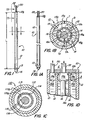
- a gas-generation cell 10 comprising a cathode 12 which also serves as an outer containment shell, a separation membrane 14 ( Figure 1B ) and an anode 16.
- Cathode 12 has an inner surface 12a and anode 16 has an outer surface 16a.
- Surfaces 12a and 16a are active electrode surfaces which are exposed to, and in contact with, a liquid electrolyte 18 which is contained within electrolyte chamber 15 of gas-generation cell 10.
- Electrolyte chamber 15 is defined by the space between surfaces 12a and 16a.
- separation membrane 14 divides electrolyte chamber 15 into an anode sub-chamber 15a containing an anode portion 18a of electrolyte 18, and a cathode sub-chamber 15b, containing a cathode portion 18b of electrolyte 18.
- anode 16, cathode 12, and separation membrane 14 are configured coaxially, with the tubular separation membrane 14 disposed coaxially within the tubular cathode 12 and the rod-shaped anode 16 disposed coaxially within the separation membrane 14.
- cathode 12 and separation membrane 14 are of annular shape in transverse cross section, thereby imparting the same cross-sectional annular shape to the anode and cathode sub-chambers 15a and 15b.
- Cathode 12 is separated from the anode and sealed at one end against high pressure by seal 13 ( Figures 1 and 1A ).
- a gas-tight seal 12b ( Figure 1D ) closes the other end of cell 10.
- Gas-tight seal 12b is shown in simplified schematic form for simplicity of illustration; its construction will be similar to that of gas-tight seal 13 except that, as shown in Figure 1D , the anode 16 does not protrude through it, but stops short of it.
- a pair of gas take-off lines 20 and 22 protrudes through gas-tight seal 12b to establish liquid-and gas-flow communication with the interior of gas-generation cell 10, as described below.
- the cathode 12 serves as the hydrogen-generating electrode and the anode 16 serves as the oxygen-generating electrode.
- the illustrated configuration of cell 10 separates the liquid electrolyte 18 into an anode electrolyte portion 18a and a cathode electrolyte portion 18b.
- the liquid electrolyte may be, for example, a 25% to 28% by weight KOH aqueous solution contained within electrolyte chamber 15, i.e., between the electrodes 12,16 on both sides of the separation membrane 14.
- a plurality of individual gas-generation cells formed in this manner may be assembled into an array for use in an electrolyzer, as described below.
- DC direct current
- hydrogen gas is generated at cathode 12 within cathode sub-chamber 15b of electrolyte chamber 15, and oxygen gas is generated at anode 16 within anode sub-chamber 15a of electrolyte chamber 15.
- the cathode component may, but need not necessarily, also serve as the pressure boundary of the electrolysis cell. That is, in some embodiments the cathode also serves as the containment or pressure vessel, whereas in other embodiments the co-axially disposed anode, separation membrane and cathode may all be contained within a pressure vessel, enabling thin- wall construction of the cathode as well as the anode.
- the wall thickness T of cathode 12 and consequently the outside diameter D of the cell 10 is dictated by the desired generation pressure, by material properties such as yield strength and electrical conductivity of the metal from which cathode 12 is made, and by practical considerations limiting the wall thickness of cathode 12 which, as noted above, also may serve as the containment vessel of cell 10.
- the diameter D of individual cells for generation at 68,948 KPa (10,000 psig).
- the wall thickness T of cathode 12 is determined by the desired gas-generation rate, generation pressure, and annular flow gaps.
- the length L of the cell 10 is from about 2 to 6 feet (about 0.61 to 1.83 meters).
- the annular flow gaps are shown in Figure 1B by the radial dimension lines go (cathode annular flow gap) and ga (anode annular flow gap).
- Typical dimensions for the cathode annular flow gap gc are from about 3/16 to 3/8 inches (about 0.48 to 0.96 cm), and for the anode annular flow gap ga are from about 1/8 to 1/4 inches (about 0.32 to 0.64cm).
- a simple construction, shown in Figure 1D is used to maintain the balance of pressure across the separation membrane 14 within the individual cells 10 to within 2 inches of water (less than 0.68 KPa (0.1 psig). Maintaining such pressure balance enables maintaining product (hydrogen) purity because the separation membrane 14 cannot seal against gas leakage at pressure differentials exceeding a few inches of water.
- Gas-tight seal 12b has a circular flange 11 on the inside thereof in which is formed a groove (unnumbered) within which the end of separation membrane 14 is received to provide a gas-tight seal between cathode disengagement space 19a and anode disengagement space 19b.
- a similar grooved-flange construction may or may not be supplied at the inside of seal 13 ( Figures 1 and 1A ) to seal the opposite end of separation membrane 14.
- Gas off-take line 20 transports hydrogen gas from cathode disengagement space 19a ( Figure 1D ) within cell 10 above the level 1 of cathode electrolyte portion 18b of liquid electrolyte 18.
- Gas take-off line 22 transports oxygen gas from anode disengagement space 19b within cell 10 above the level 1'of anode electrolyte portion 18a of a liquid electrolyte 18.
- the respective hydrogen and oxygen disengagement spaces are isolated from each other by a gas-tight bulkhead structure (not shown).
- Figure 1C shows a second embodiment of the invention, wherein parts identical or similar to those of the embodiment of Figure 1B are numbered 100 higher than the numbers used in Figure 1B .
- the parts and their function of cell 110 of Figure 1C are identical to those of the corresponding parts of the embodiment of Figure 1B , and therefore a description of their structure and function is not repeated.
- anode 112 is not designed to resist the operating pressures of cell 110, and there is therefore provided a pressure vessel 113 which is separate from, but surrounds and contacts, the outer surface (unnumbered) of cathode 112.
- Pressure vessel 113 has end portions (not shown) which encase the first and second ends of cell 110 to provide an effective pressure vessel for cell 110.
- the illustrated configuration of cell 10 enables optimization of the electrode areas for the cathode and anode. Because the gas-generation rate (of hydrogen) at the cathode is twice the gas-generation rate (of oxygen) at the anode, the respective surface areas of cathode inner surface 12a and anode outer surface 16a ideally should have the same 2: 1 ratio, or at least an approximation thereof, to allow the maximum gas-generation rate for a cell of given dimensions.
- the gas-generation rate is normally determined by the surface area 12a of the cathode for a given material and surface conditions. In prior art parallel plate electrode configurations, where the anode and cathode are of equal surface area, there is a wasteful excess of anode surface area.
- the diameter of the anode is smaller than the diameter of the cathode as measured at its inner surface 12a.
- the anode (outer) surface area is therefore smaller than the inner surface area of the cathode.
- the anode (outer) surface and the cathode inner surface are the surfaces in contact with the liquid electrolyte and therefore constitute the active electrode surfaces.
- the respective electrode diameters and annular flow gaps can be established to create a cathode-to-anode active surface area ratio near or at the optimum 2 to 1 value.
- the separation membrane 14 of Figure 1B and the separation membrane 114 of Figure 1C will be dimensioned and configured so that the volume of sub-chambers 15b and 115b are approximately twice the volume of their respective associated sub-chambers 15a and 115a.
- the individual cells 10 are sealed by providing a seal between the anode 16 and the containment vessel provided by the cathode 12 at each end of the latter.
- the seal must provide low voltage (-2 volts) electrical isolation between the anode and cathode as well as sealing the cell 10 against liquid leakage with internal pressures in the cell of up to 68,948 KPa (10,000 psig) or more.
- Figure 2 is an illustration of a simple and effective seal design.
- the seal 13 is comprised of four basic components.
- An anode-sealing collar 24 is made of metal and is welded to the anode 16 at an appropriate location to align it with the lower end of cathode 12 ( Figure 1 ).
- Collar 24 may alternately be made by machining anode 16 from a larger-diameter rod so that collar 24 and anode 16 are of one-piece, unitary construction.
- An O- ring groove 24a is machined into the bottom end surface (unnumbered) of sealing collar 24 to receive an O-ring 24b.
- An electrical isolation bushing 26 is of cup shape and is made of a dielectric material to provide an electrical isolation piece through which the anode 16 passes.
- Bushing 26 is made from non-conducting material and has an O-ring groove (unnumbered) formed about the periphery thereof to receive an O-ring 26a.
- a high-pressure end fitting28 is made of metal and provides an end piece through which the anode passes and which seals the lower end of the cathode 12 by means of either threading or welding.
- the outer diameter of the end fitting28 may be threaded to provide exterior threads 28a to mate with inner diameter threads (not shown) provided at both ends of the inner surface 12a ( Figure 1B ) of the containment vessel wall provided by cathode 12.
- the end fitting may be welded to the lower end of the cathode. Either arrangement forms a seal against the high gas pressure generated within cathode 12.
- An electrical insulating sleeve 30 has a sleeve bore 33 extending through it and is disposed within the end-fitting bore (unnumbered) extending through high-pressure end fitting 28. Anode 16 is received within the sleeve bore 33. Electrical insulating sleeve 30 thus serves to maintain electrical isolation between the anode 16 and cathode 12 outside the pressurized area within cathode 12.
- Sleeve 30 also has an end flange 30a that electrically isolates a nut 32 which is threaded onto the anode 16, at threads 17 formed at or near the end thereof, and is used to preload and hold the entire assembly together.
- a washer 34 is interposed between nut 32 and end flange 30a.
- anode-sealing collar 24, electrical isolation bushing 26, and end fitting 28 are so dimensioned and configured as to position and maintain anode 16 at the center of the electrolyte chamber 15 ( Figure 1B ) defined between cathode 12 and anode 16.
- Structure is similarly provided to position and hold separation membrane 14 in place concentrically relative to anode 16 and cathode 12. This may be accomplished by one or more suitable positioning members which are dimensioned and configured to position and maintain separation membrane 14 in place.
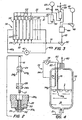
- an electrolyzer apparatus 36 comprises an array 38 of individual cells 10 across each of which an electric potential is imposed by an electrical energy source provided, in the illustrated embodiment, by a DC generator 40. Electrical leads from generator 40 to cells 10 are schematically illustrated by electrical leads 42a, 42b. A given hydrogen production capacity for electrolyzer apparatus 36 is attained by appropriately sizing individual cells 10 and selecting an appropriate number of such cells for connection to a common manifold system as described below.
- a method for producing hydrogen is carried out by utilizing an electrolytic apparatus as described above to produce hydrogen (and oxygen by-product) at an elevated pressure of up to 68,948 KPa (10,000 pounds per square inch gauge (“psig"), for example, a pressure range from 0 to 68,948 KPa (10,000 psig).
- the upper end of this pressure range (from 34,474 KPa to 68,948 KPa (5,000 to 10,000 psig) is uniquely well suited to directly provide hydrogen fuel for storage in high-pressure storage vessels of hydrogen-based fuel cell-powered automobiles or other self-propelled vehicles, or portable or stationary devices.
- Any pressure ranges between 0 to 68,948 KPa (0 to 10,000 psig) may of course be used. Typical of such intermediate ranges are pressures above 20,684 KPa (3,000 psig), e.g., from above 20,684 KPa (3,000 psig) to 68,948 KPa (10,000 psig); from 24132 KPa to 55158 KPa (3,500 psig to 8,000 psig); and from 24132 KPa to 68,948 KPa (3,500 psig to 10,000 psig).
- Generation of hydrogen at pressures above 68,948 KPa (10,000 psig) may be feasible in certain aspects of the invention, provided that it is economically practical for the contemplated use to provide pressure vessels and associated equipment capable of sustaining such high pressures.
- An electrolyte reservoir 44 is supplied by make-up water pump 48 with make-up water from water treatment and storage zone 46 in order to replenish water which was dissociated by electrolysis to provide product hydrogen and oxygen.
- Electrolyte is taken from the electrolyte reservoir 44 and is fed by supply line 45 to electrolyte-replenishing pump 50 from which it is transported via electrolyte feed line 51 to an electrolyte manifold 52 which supplies the electrolyte liquid to individual cells 10 via electrolyte feed lines 54.
- Hydrogen gas generated within cells 10 and some electrolyte 18 ( Figure 1B ) is removed via gas off-take lines 20 and hydrogen manifold line 21 to hydrogen separator 56, wherein liquid electrolyte 18 ( Figure 1B ) is separated from the hydrogen gas.
- Hydrogen product from hydrogen separator 56 is flowed via hydrogen discharge line 60 and is free to flow through check valve 62 and into hydrogen storage tank 63, or to use or further treatment. Separated electrolyte provides a liquid seal within hydrogen separator 56. Hydrogen pressure will continue to rise as hydrogen is supplied to the fixed volume storage tank 63.
- oxygen and liquid electrolyte 18 is removed from cells 10 by gas off-take lines 22, which supply oxygen manifold line 23.
- the oxygen gas and liquid electrolyte 18 flow via line 23 to oxygen separator 64 in which liquid electrolyte is separated from the oxygen.
- Separated oxygen flows via oxygen discharge line 68 at a rate, which is controlled by oxygen pressure regulator 70, to an oxygen storage tank (not shown) or to venting or to use or further treatment.
- Separated electrolyte provides a liquid seal within oxygen separator 64.
- the oxygen flow rate is controlled to maintain the liquid level in separator 64 to be equal to the liquid level in separator 56. The same operational function could be performed by maintaining the pressure in separator 64 to be equal to the pressure in separator 56.
- the separators 56 and 64 are sized in cross-section so as to act as a liquid trap preventing or greatly reducing electrolyte carry over and loss of potassium hydroxide.
- Make-up potassium hydroxide may be added to the system as needed, e.g., manually during shutdowns for periodic maintenance.
- the oxygen gas exiting the oxygen separator is connected to the gas space over the liquid in the electrolyte reservoir to maintain reservoir pressure at near cell pressure. This enables the electrolyte supply pump to operate as a low differential pressure circulator. Make-up water is only added to the electrolyte reservoir when level sensors in the reservoir (not shown) indicate the need to replenish the reservoir liquid.
- Check valve 62 allows the hydrogen product gas to flow through line 60 into a storage tank 63 or to further processing or use when the hydrogen gas pressure in cells 10 exceeds that in line 60, e.g., in the hydrogen storage tank 63.
- a pressure sensor (not shown) acts to automatically shut off the electrical current to the electrolyzer apparatus 36 when the maximum design pressure in hydrogen storage tank 63 has been reached.
- the liquid level in the hydrogen separator 56 is sensed by a simple level-sensing device, shown in Figure 4 , which is mounted on hydrogen separator 56.
- Level-sensing device 72 comprises a pair (or more) of electrically isolated probes 74,76 that extend into the separator 56 at lengths that define the maximum and minimum desired level 1 of liquid electrolyte 18 in the separator 56 at, respectively, probe tips 74a and 76a.
- the electrically isolating seal is essentially the same design as the cathode/anode seal 13 ( Figures 1 and 1A ) described above.
- a low-voltage source 78 is connected by electrical leads 80, 82 to probes 74, 76 and is grounded to separator 56 by electrical ground lead 84. Electrical continuity is checked between the probes 74, 76 and the shell of separator 56. If the electrolyte level drops below the lower level, i.e., no continuity is found in either probe, the electrolyte supply pump 50 is actuated and electrolyte is sent to the cells. When electrical continuity is sensed on both probes 74 and 76, the electrolyte has reached the maximum level and the electrolyte supply pump 50 is stopped, and no more electrolyte is sent to the cells. If the conductive electrolyte is between the two probe lengths, i.e., continuity is found on one probe only, the make-up water pump 48 status is left unchanged, whether on or off, until one of the two above mentioned conditions is met.
- the flow of oxygen can be easily controlled to minimize the pressure differential between the separators (and therefore across the diaphragm) in either of two ways: differential pressure sensing, or liquid-level sensing.
- the flow from the oxygen separator 64 is controlled by pneumatically actuated pressure regulator valve 70.
- the actuator diaphragm (not shown) of valve 70 is connected by lines (not shown) to sense the pressure differential between the gas in the oxygen separator 64 and hydrogen separator 56, and opens to vent the gas space of oxygen separator 64 to maintain a set pressure differential.
- This pressure differential is set at near zero, e.g., a pressure differential of from 1.1721 KPa to 1.379 KPa (0.17 psig to 0.2 psig), so that the pressure balance inherently keeps the liquid levels in the two separators 56, 64 stable and equal to within the differential pressure setting.
- valve 70 In the direct liquid-level sensing technique, a liquid-level sensor identical to liquid- level sensing of Figure 4 is installed on device 72 in the oxygen separator 64. In this case the valve 70 regulating the flow of gas from the oxygen separator 64 cycles between high and low (or on and off) settings. This simple level-control scheme is satisfactory for operation of cells 10.
- the setting of valve 70 is determined by the liquid electrolyte level in separator 64 as follows. When the valve 70 is at its high flow setting and the liquid level in the oxygen separator 64 rises and reaches the high level contact (analogous to probe tip 74a of Figure 4 ), the valve 70 is switched to its low flow-rate position by a suitable electronic control device (not shown). When the valve 70 is in the low flow setting and the liquid level drops and reaches the low level contact (analogous to probe tip 76a of Figure 4 ), the valve 70 is switched to its high flow-rate position by the control device.
- the electrolyte is circulated in a continuous recycle operation.
- This continuous-operation embodiment enables the production of high-pressure hydrogen with the potential to increase the length, and therefore the production rate, for a given cell.
- the individual cell length is limited by a combination of the cell dimension (flow gap), gas volume generation rate, and bubble rise rate. Circulating the electrolyte upward through the cell at appropriate rates in a continuous recycle embodiment of the invention will increase the bubble rise rate via entrainment and allow longer cathode and electrode length for otherwise similarly dimensioned cells.
- separator reservoirs (items 56 and 64 in Figure 3 ) would be altered by adding a return path for the electrolyte from separators 56 and 64 back to the electrolyte reservoir (item 44 in Figure 3 ).
- the remainder of the apparatus schematically shown in Figure 3 and the basic control system as described above for the batch mode embodiment stays largely unaltered for the electrolyte-circulating continuous recycle embodiment.
- the present invention provides at least the following advantages over the prior art.
- the apparatus and method of the present invention can produce such high-pressure hydrogen without need for a separate compressor to pressurize the product hydrogen gas.
- Producing 68,948 KPa (10,000 psig) is key to supplying compressed hydrogen gas for fuel-cell-powered or internal combustion engine-powered vehicles at acceptable volume-to-weight ratios for onboard storage that yields a single-tank driving range equivalent to gasoline powered vehicles.
- the present invention allows high-pressure hydrogen production to be performed in a unique way that reduces the component cost and system complexity so that the equipment is easily affordable by individuals for commuter vehicle home fueling and for small fleet fueling applications.
- the invention is scalable to any given production capacity and is also practical for service-station type applications for dispensing of hydrogen to fuel-cell-powered vehicles and equipment.
- the apparatus and method of the present invention may be utilized to generate pressurized hydrogen on site at locations such as service stations for hydrogen fuel cell-powered automobiles; service stations, hardware/home improvement stores, and local energy distributors for retail sale of hydrogen fuel via high-pressure canisters; and in residences, factories and office buildings for on-site energy storage and/or use in fuel cell or internal combustion engine- based portable power supply or home, garden or other appliance applications.
Landscapes
- Chemical & Material Sciences (AREA)
- Engineering & Computer Science (AREA)
- Chemical Kinetics & Catalysis (AREA)
- Electrochemistry (AREA)
- Materials Engineering (AREA)
- Metallurgy (AREA)
- Organic Chemistry (AREA)
- Inorganic Chemistry (AREA)
- Electrolytic Production Of Non-Metals, Compounds, Apparatuses Therefor (AREA)
Claims (22)
- Unter Druck stehende Elektrolysezelle (10) mit einem ersten und einem zweiten, entgegengesetzten Ende, Folgendes aufweisend:eine rohrförmig aufgebaute Kathode (12), die an eine Gleichstromquelle angeschlossen werden kann und eine aktive Kathodeninnenfläche (12a), an der Wasserstoff erzeugt wird, und eine Kathodenaußenfläche festlegt;eine Anode (16), die an eine Gleichstromquelle angeschlossen werden kann, eine aktive Anodenaußenfläche (16a) festlegt, an der Sauerstoff erzeugt wird, und in der Kathode angeordnet ist, um mit dieser eine ringförmige Elektrolytkammer (15) zu bilden, die zwischen der Kathodeninnenfläche und der Anodenaußenfläche angeordnet ist;eine rohrförmig aufgebaute Trennmembran (14), die in der Elektrolytkammer zwischen der Kathode und der Anode angeordnet ist, um die Elektrolytkammer (15) in eine Anodenteilkammer (15a) und eine Kathodenteilkammer (15b) zu unterteilen, wobei die Trennmembran gegen den Durchgang von Gasen durch sie hindurch abdichtet, aber den Durchgang von in einer Flüssigkeit vorhandenen Ionen zulässt;eine erste und zweite gasdichte Dichtung (12b, 13), die am ersten bzw. zweiten, entgegengesetzten Ende der Zelle angeordnet sind; undeinen Gasabzugsanschluss (20, 22), der in Gasflussverbindung mit der Elektrolytkammer steht, um die in der Elektrolytkammer erzeugten Wasserstoff- und Sauerstoffgase abzuziehen,dadurch gekennzeichnet, dass die Kathode (12) einen äußeren Drucksicherheitsbehälter aufweist; undwobei mindestens eine der gasdichten Dichtungen (12b, 13) aufweist:eine anodenabdichtende Manschette (24), die an der Anode (16) angrenzend an ein Ende von dieser befestigt ist;eine Elektroisolationsdurchführung (26), durch welche die Anode hindurchgeht, und die an der Anode zwischen der anodenabdichtenden Manschette und dem einen Ende der Anode befestigt ist, wobei die Durchführung die anodenabdichtende Manschette in Eingriff nimmt;ein Endanschlussstück (28), das die Durchführung in Eingriff nimmt und eine gasdichte Abdichtung der Kathode (12) an einem Ende von dieser bereitstellt; undeine elektrisch isolierende Hülse (30), die in dem Endanschlussstück (28) angeordnet ist und die Anode (16) aufnimmt.
- Elektrolysezelle nach Anspruch 1, wobei der Gasabzugsanschluss separate Abzugsanschlüsse (20, 22) aufweist, die dazu ausgelegt sind, Wasserstoff, der in der Kathodenteilkammer erzeugt wurde, separat vom Sauerstoff abzuziehen, der in der Anodenteilkammer erzeugt wurde.
- Elektrolysezelle nach Anspruch 1, wobei die Kathode (12), die Trennmembran (14) und die Anode (16) alle in Bezug aufeinander koaxial angeordnet sind, und die Kathodeninnenfläche (12a), die Anodenaußenfläche (16a) und die Trennmembran (14) im Querschnitt jeweils kreisförmig aufgebaut sind.
- Elektrolysezelle nach Anspruch 1, Anspruch 2 oder Anspruch 3, wobei das Verhältnis der Kathodeninnenfläche (12a) zur Anodenaußenfläche (16a) 2 : 1 beträgt.
- Elektrolysezelle nach Anspruch 1, Anspruch 2 oder Anspruch 3, wobei das Verhältnis des Volumens der Kathodenteilkammer (15b) zur Anodenteilkammer (15a) 2 : 1 beträgt.
- Elektrolysezelle nach Anspruch 1, wobei der Drucksicherheitsbehälter fähig ist, Gas mit einem hohen Druck zu enthalten, der mindestens 68,948 KPa (10 psig) und nicht mehr als 68.948 KPa (10.000 psig) beträgt.
- Elektrolysezelle nach Anspruch 1, wobei die Elektroisolationsdurchführung (26) napfförmig ist, um eine Vertiefung zu bilden, in der die anodenabdichtende Manschette (24) aufgenommen ist; wobei das Endanschlussstück (28) eine sich durch dieses erstreckende Längsbohrung hat, und die Elektroisolationsdurchführung (26) und das eine Ende der Anode (16) in der Längsbohrung aufgenommen und am Endanschlussstück befestigt sind.
- Elektrolysevorrichtung, Folgendes aufweisend:(a) mehrere Elektrolysezellen (10) nach Anspruch 1,(b) erste Gasflussleitungen (20), die in Gasflussverbindung zwischen den jeweiligen Kathodenteilkammern (15b) der Elektrolysezellen und einem Wasserstoffabscheider (56) angeschlossen sind; und(c) zweite Gasflussleitungen (22), die in Gasflussverbindung zwischen den Anodenteilkammern (15a) der Elektrolysezellen und einem Sauerstoffabscheider (64) angeschlossen sind.
- Elektrolysevorrichtung nach Anspruch 8, wobei der Wasserstoffabscheider (56) dazu ausgelegt ist, ein der Kathodenteilkammer (15b) entzogenes Wasserstoff- und Flüssigelektrolytgemisch aufzunehmen;
der Sauerstoffabscheider (64) dazu ausgelegt ist, ein der Anodenteilkammer (15a) entzogenes Sauerstoff- und Flüssigelektrolytgemisch aufzunehmen; und Steuereinrichtungen zum Steuern des Verhältnisses der Flüssigkeitspegelveränderung im Wasserstoff- und Sauerstoffabscheider (56, 64) vorgesehen sind, um die Druckdifferenz zwischen dem entzogenen Wasserstoff und Sauerstoff aufrechtzuerhalten. - Elektrolysevorrichtung nach Anspruch 8, darüber hinaus erste elektrische Verbinder (42a) an den jeweiligen Anoden der Zellen und zweite elektrische Verbinder (42b) an den jeweiligen Kathoden der Zellen umfassend, wobei die ersten und zweiten elektrischen Verbinder zum Anschließen der Zellen an eine Gleichstromquelle (40) bemessen und aufgebaut sind, um einen Spannungsabfall an der Anode und Kathode jeweiliger der Zellen zu erzeugen.
- Verfahren zur Elektrolyse von Wasser, um daraus unter Druck stehenden Wasserstoff und Sauerstoff zu erzeugen, und zwar unter Nutzung einer Elektrolysevorrichtung, die eine oder mehrere Elektrolysezelle/n (10) aufweist, wobei die Zellen einzeln aufweisen:(i) eine rohrförmig aufgebaute Kathode (12), die selbst dazu ausgelegt ist, einen Drucksicherheitsbehälter bereitzustellen, in dem eine stabförmige Anode (16) angeordnet ist, um eine ringförmige Elektrolytkammer (15) zwischen der Kathode und der Anode zu bilden,(ii) eine rohrförmig aufgebaute Trennmembran (14), die in der Elektrolytkammer (15) zwischen der Kathode und der Anode angeordnet ist, um die Elektrolytkammer (15) in eine Anodenteilkammer (15a) und eine Kathodenteilkammer (15b) zu unterteilen und die Teilkammern gegen einen Gasfluss zwischen diesen abzudichten, wobei das Verfahren die folgenden Schritte umfasst:(a) Einleiten einer wässrigen Elektrolytlösung (18) in beide Teilkammern der Elektrolytkammer;(b) Bewirken eines Gleichspannungsabfalls an den jeweiligen Anoden und Kathoden der Zellen, um Wasser an der Kathode zu Wasserstoff und an der Anode zu Sauerstoff aufzuspalten;(c) separates Entziehen von Wasserstoff und Sauerstoff aus der einen oder den mehreren Elektrolysezelle/n, indem ein der Kathodenteilkammer (15b) entzogenes Wasserstoff- und Flüssigelektrolytgemisch zu einem Wasserstoffabscheider (56) und ein der Anodenteilkammer (15a) entzogenes Sauerstoff- und Flüssigelektrolytgemisch zu einem Sauerstoffabscheider (64) geleitet wird, und(d) Unterhalten einer ersten und zweiten gasdichten Dichtung (12b, 13), die am ersten bzw. zweiten, entgegengesetzten Ende der einen oder mehreren Zelle/n (10) angeordnet sind, wobei mindestens eine der gasdichten Dichtungen (12b, 13) aufweist:eine anodenabdichtende Manschette (24), die an der Anode (16) angrenzend an ein Ende von dieser befestigt ist;eine Elektroisolationsdurchführung (26), durch welche die Anode hindurchgeht, und die an der Anode zwischen der anodenabdichtenden Manschette und dem einen Ende der Anode befestigt ist, wobei die Durchführung die anodenabdichtende Manschette in Eingriff nimmt;ein Endanschlussstück (28), das die Durchführung in Eingriff nimmt und eine gasdichte Abdichtung der Kathode (12) an einem Ende von dieser bereitstellt; undeine elektrisch isolierende Hülse (30), die in dem Endanschlussstück (28) angeordnet ist und die Anode aufnimmt.
- Verfahren nach Anspruch 1, darüber hinaus umfassend:(e) Aufrechterhalten einer Druckdifferenz zwischen dem entzogenen Wasserstoff und Sauerstoff, indem die jeweiligen Elektrolytteilkammern (15a, 15b) dazu ausgelegt werden, miteinander in Flüssigkeitsverbindung zu stehen, und das Verhältnis der Flüssigkeitspegelveränderung in den Wasserstoff- und Sauerstoffabscheidern (56, 64) gesteuert wird, um die Druckdifferenz zwischen dem entzogenen Wasserstoff und Sauerstoff aufrechtzuerhalten.
- Verfahren nach Anspruch 11 oder Anspruch 12, wobei der Wasserstoff und der Sauerstoff bei einem hohen Druck erzeugt werden, der mindestens 68,948 KPa (10 psig) beträgt.
- Verfahren nach Anspruch 12 oder Anspruch 13, wobei der hohe Druck nicht höher als 68.948 KPa (10.000 psig) ist.
- Verfahren nach Anspruch 12 oder Anspruch 13, wobei der hohe Druck nicht höher als 34.474 KPa (5.000 psig) ist.
- Verfahren nach Anspruch 12 oder Anspruch 13 oder Anspruch 14 oder Anspruch 15, darüber hinaus umfassend, die Druckdifferenz zwischen dem aus den Zellen entzogenen Wasserstoff und Sauerstoff auf nicht mehr als 1,7237 KPa (0,25 psig) zu halten.
- Verfahren nach Anspruch 16, umfassend, die Druckdifferenz auf nicht mehr als ca. 1,1721 KPa (0,17 psig) zu halten.
- Verfahren nach Anspruch 12 oder Anspruch 13 oder Anspruch 14 oder Anspruch 15, wobei das Steuern des Verhältnisses einer Flüssigkeitspegelveränderung in den Wasserstoff- und Sauerstoffabscheidern (56, 64) umfasst: Elektrolyt und Produkt Wasserstoff in den Wasserstoffabscheider (56) einströmen zulassen, Elektrolyt und Nebenprodukt Sauerstoff in den Sauerstoffabscheider (64) einströmen zu lassen, Erfassen der jeweiligen Flüssigkeitspegel des Elektrolyts (18) im Wasserstoff- und Sauerstoffabscheider, und Steuern der Flüssigkeitspegel, um eine Druckdifferenz zwischen dem aus den Zellen entzogenen Wasserstoff und Sauerstoff auf nicht mehr als ca. 1,379 KPa (0,2 psig) zu halten.
- Verfahren nach Anspruch 12 oder Anspruch 13 oder Anspruch 14 oder Anspruch 15, wobei man den Elektrolyt (18) in einem Dauerbetrieb durch die Elektrolysevorrichtung zirkulieren lässt.
- Verfahren nach Anspruch 12 oder Anspruch 13 oder Anspruch 14 oder Anspruch 15, wobei es sich bei der wässrigen Elektrolytlösung (18) um eine wässrige Kaliumhydroxidlösung handelt.
- Verfahren nach Anspruch 12 oder Anspruch 13 oder Anspruch 14 oder Anspruch 15, wobei die Elektrolysevorrichtung mehrere Elektrolysezellen (10) umfasst.
- Elektrolysevorrichtung nach Anspruch 1 oder Anspruch 8, wobei die elektrisch isolierende Hülse (30) eine elektrische Isolierung zwischen der Anode (16) und der Kathode (12) außerhalb des unter Druck stehenden Bereichs in der Kathode (12) aufrechterhält.
Applications Claiming Priority (3)
| Application Number | Priority Date | Filing Date | Title |
|---|---|---|---|
| US44957203P | 2003-02-21 | 2003-02-21 | |
| US449572P | 2003-02-21 | ||
| PCT/US2004/005182 WO2004076721A2 (en) | 2003-02-21 | 2004-02-19 | Electrolyzer apparatus and method for hydrogen production |
Publications (3)
| Publication Number | Publication Date |
|---|---|
| EP1597414A2 EP1597414A2 (de) | 2005-11-23 |
| EP1597414A4 EP1597414A4 (de) | 2006-07-26 |
| EP1597414B1 true EP1597414B1 (de) | 2011-04-06 |
Family
ID=32927537
Family Applications (1)
| Application Number | Title | Priority Date | Filing Date |
|---|---|---|---|
| EP04712926A Expired - Lifetime EP1597414B1 (de) | 2003-02-21 | 2004-02-19 | Elektrolyseapparatur und verfahren zur herstellung von wasserstoff |
Country Status (9)
| Country | Link |
|---|---|
| US (1) | US7510633B2 (de) |
| EP (1) | EP1597414B1 (de) |
| JP (1) | JP4611281B2 (de) |
| CN (1) | CN1751139B (de) |
| AT (1) | ATE504674T1 (de) |
| AU (1) | AU2004214963B2 (de) |
| CA (1) | CA2513539A1 (de) |
| DE (1) | DE602004032110D1 (de) |
| WO (1) | WO2004076721A2 (de) |
Cited By (1)
| Publication number | Priority date | Publication date | Assignee | Title |
|---|---|---|---|---|
| WO2023085938A1 (en) | 2021-11-11 | 2023-05-19 | Hydro-Gen Bv | High-pressure electrolysis device |
Families Citing this family (79)
| Publication number | Priority date | Publication date | Assignee | Title |
|---|---|---|---|---|
| US9168318B2 (en) | 2003-12-30 | 2015-10-27 | Oculus Innovative Sciences, Inc. | Oxidative reductive potential water solution and methods of using the same |
| US8172990B2 (en) | 2009-02-17 | 2012-05-08 | Mcalister Technologies, Llc | Apparatus and method for controlling nucleation during electrolysis |
| JP4909521B2 (ja) * | 2005-03-23 | 2012-04-04 | 日立造船株式会社 | 固体高分子型水電解槽 |
| EP1863502B1 (de) | 2005-03-23 | 2018-09-12 | Sonoma Pharmaceuticals, Inc. | Verfahren zur behandlung von hautgeschwüren mit einer wasserlösung mit oxidations- und reduktionspotenzial |
| US20060228619A1 (en) * | 2005-04-12 | 2006-10-12 | General Electric Company | Electrochemical cell structure |
| CN101189017B (zh) | 2005-05-02 | 2013-04-03 | 奥古露丝创新科学公司 | 在牙科应用中使用氧化还原电位水溶液的方法 |
| JP2008546626A (ja) * | 2005-06-23 | 2008-12-25 | ジーアールディーシー,エルエルシー | 水素の効率的な生産 |
| BRPI0706671A2 (pt) | 2006-01-20 | 2011-04-12 | Oculus Innovative Sciences Inc | métodos de tratamento ou prevenção de inflamação e hipersensibilidade com solução aquosa com potencial de oxirredução |
| GB0605393D0 (en) * | 2006-03-16 | 2006-04-26 | Itm Fuel Cells Ltd | Composite menbranes for electrochemical cells |
| WO2008064159A1 (en) * | 2006-11-19 | 2008-05-29 | Wood Stone Corporation | Hydrogen producing unit |
| US20100252445A1 (en) * | 2007-07-07 | 2010-10-07 | Donald James Highgate | Electrolysis of Salt Water |
| DE102008003126A1 (de) * | 2007-08-06 | 2009-02-12 | Clean World Energies Gmbh | Verbrennungskraftmaschine und Verfahren zum Betrieb einer Verbrennungskraftmaschine |
| US20090159454A1 (en) * | 2007-12-20 | 2009-06-25 | Air Products And Chemicals, Inc. | Divided electrochemical cell and low cost high purity hydride gas production process |
| US20100000876A1 (en) * | 2008-07-02 | 2010-01-07 | Sandbox Energy Systems, LLC | Caviation assisted sonochemical hydrogen production system |
| US9255333B2 (en) * | 2008-10-15 | 2016-02-09 | GM Global Technology Operations LLC | High pressure proton exchange membrane based water electrolyzer system |
| MY154200A (en) * | 2009-02-17 | 2015-05-15 | Mcalister Technologies Llc | Apparatus and method for controlling nucleation during electrolysis |
| CA2752825C (en) | 2009-02-17 | 2014-01-14 | Mcalister Technologies, Llc | Electrolytic cell and method of use thereof |
| US9040012B2 (en) | 2009-02-17 | 2015-05-26 | Mcalister Technologies, Llc | System and method for renewable resource production, for example, hydrogen production by microbial electrolysis, fermentation, and/or photosynthesis |
| US8075750B2 (en) | 2009-02-17 | 2011-12-13 | Mcalister Technologies, Llc | Electrolytic cell and method of use thereof |
| JP5341547B2 (ja) * | 2009-02-18 | 2013-11-13 | 本田技研工業株式会社 | 水電解システム |
| US9534303B2 (en) | 2009-04-30 | 2017-01-03 | GM Global Technology Operations LLC | High pressure electrolysis cell for hydrogen production from water |
| MX348304B (es) | 2009-06-15 | 2017-06-02 | Invekra S A P I De C V | Solucion que contiene acido hipocloroso y metodos para usar la misma. |
| US20110017607A1 (en) * | 2009-07-22 | 2011-01-27 | Green On Demand, LLP (G.O.D.) | On demand hydrogen production unit and method for the on demand production of hydrogen |
| DE102009035440A1 (de) * | 2009-07-31 | 2011-02-03 | Siemens Aktiengesellschaft | Verfahren und Vorrichtung zur Erzeugung von Wasserstoff und Sauerstoff |
| WO2011020172A1 (en) * | 2009-08-19 | 2011-02-24 | Next Hydrogen Corporation | Proton exchange membrane water electrolyser cell module design |
| US8147661B2 (en) * | 2009-08-31 | 2012-04-03 | Green On Demand Gmbh | Unit for the electrolysis of water |
| US8685224B2 (en) * | 2009-09-04 | 2014-04-01 | Innovative Energy Systems And Design, Llc | Method and apparatus for hydrogen generation |
| CN102639754B (zh) * | 2009-12-01 | 2015-03-11 | 威斯康星校友研究基金会 | 缓冲氧化钴催化剂 |
| US20110147204A1 (en) | 2009-12-17 | 2011-06-23 | Green On Demand, LLP (G.O.D.) | Apparatus for on demand production of hydrogen by electrolysis of water |
| US8454808B2 (en) | 2010-03-15 | 2013-06-04 | Hno Greenfuels, Inc. | Hydrogen supplemental system for on-demand hydrogen generation for internal combustion engines |
| US9453457B2 (en) | 2010-03-15 | 2016-09-27 | HNO Green Fuels, Inc. | Hydrogen supplemental system for on-demand hydrogen generation for internal combustion engines |
| US9574492B2 (en) | 2010-03-15 | 2017-02-21 | HNO Green Fuels, Inc. | Portable hydrogen supplemental system and method for lowering particulate matter and other emissions in diesel engines at idle |
| US8499722B2 (en) * | 2010-05-28 | 2013-08-06 | Hno Greenfuels, Inc. | Hydrogen supplemental system for on-demand hydrogen generation for internal combustion engines |
| US9399946B2 (en) | 2010-05-28 | 2016-07-26 | Donald W. Owens | Hydrogen supplemental system for on-demand hydrogen generation for internal combustion engines |
| US9476357B2 (en) | 2010-03-15 | 2016-10-25 | HNO Green Fuels, Inc. | Method and apparatus for increasing combustion efficiency and reducing particulate matter emissions in jet engines |
| US8449735B2 (en) * | 2010-03-15 | 2013-05-28 | Hno Greenfuels, Inc. | Hydrogen supplemental system for on-demand hydrogen generation for internal combustion engines |
| US20110233069A1 (en) * | 2010-03-24 | 2011-09-29 | Rasirc | Method and system for electrochemical hydrogen generation |
| US8757107B2 (en) | 2010-05-28 | 2014-06-24 | Hno Greenfuels, Inc. | Hydrogen supplemental system for on-demand hydrogen generation for internal combustion engines |
| US9011651B2 (en) | 2010-12-09 | 2015-04-21 | Ut-Battelle, Llc | Apparatus and method for the electrolysis of water |
| US8852410B1 (en) * | 2011-01-16 | 2014-10-07 | Luke J. Turgeon | Electrolytic hydrogen generator and method |
| RU2551365C2 (ru) | 2011-02-28 | 2015-05-20 | Вито Нв | Новый сепаратор, электрохимическая ячейка с новым сепаратором и применение нового сепаратора в электрохимической ячейке |
| DE102011002104A1 (de) | 2011-04-15 | 2012-10-18 | Kumatec Sondermaschinenbau & Kunststoffverarbeitung Gmbh | Elektrolyseur |
| US9464356B2 (en) | 2011-09-21 | 2016-10-11 | Encite Llc | High pressure gas system |
| WO2013066331A2 (en) * | 2011-11-03 | 2013-05-10 | Avalence Llc | Method for controlling cell-presssure balance and separator liquid level in an electrolyzer and apparatus thereof |
| CN102603036B (zh) * | 2012-03-23 | 2014-01-22 | 烟台市马可波罗电子科技有限公司 | 一种制造氢水的装置 |
| RU2501890C1 (ru) * | 2012-05-11 | 2013-12-20 | Открытое акционерное общество "УРАЛЬСКИЙ ЭЛЕКТРОХИМИЧЕСКИЙ КОМБИНАТ" | Электролизер для получения водорода и кислорода из воды |
| CN102677084A (zh) * | 2012-05-22 | 2012-09-19 | 浙江师范大学 | 一种电解水制氢的方法和装置 |
| WO2013177700A1 (en) | 2012-05-28 | 2013-12-05 | Hydrogenics Corporation | Electrolyser and energy system |
| BR112014031220A2 (pt) | 2012-06-12 | 2017-06-27 | Univ Monash | estrutura de eletrodo com capacidade de respiração e método e sistema para uso em separação da água |
| WO2014043651A2 (en) * | 2012-09-14 | 2014-03-20 | Liquid Light, Inc. | High pressure electrochemical cell and process for the electrochemical reduction of carbon dioxide |
| US9487875B2 (en) * | 2012-12-27 | 2016-11-08 | Osaka Electro-Communication University | Producing electrolyzed liquid |
| US9546428B2 (en) | 2013-03-01 | 2017-01-17 | Osaka Electro-Communication University | Producing electrolyzed liquid |
| US9127244B2 (en) | 2013-03-14 | 2015-09-08 | Mcalister Technologies, Llc | Digester assembly for providing renewable resources and associated systems, apparatuses, and methods |
| WO2014153389A1 (en) * | 2013-03-19 | 2014-09-25 | Gilman Brian Daniel | Portable hydrogen and oxygen supply system |
| KR102355899B1 (ko) * | 2013-07-01 | 2022-02-08 | 스카이어, 아이엔씨. | 수소 시스템 및 작동 방법 |
| JP2016532008A (ja) | 2013-07-31 | 2016-10-13 | アクアハイドレックス プロプライエタリー リミテッドAquahydrex Pty Ltd | 気体拡散電極(複数可)を備えた電解合成又は電気エネルギーセル |
| CN103789784B (zh) * | 2013-11-28 | 2017-03-01 | 林信涌 | 模组化保健气体产生器 |
| CN103794810A (zh) * | 2013-12-05 | 2014-05-14 | 南通百应能源有限公司 | 一种燃料电池的制氢设备 |
| TWI550135B (zh) * | 2014-02-12 | 2016-09-21 | bo-yu Huang | Hydrogen machine |
| CN103936109B (zh) * | 2014-04-12 | 2016-08-17 | 大连双迪创新科技研究院有限公司 | 饮水电解制取装置 |
| CN104122904B (zh) * | 2014-07-16 | 2017-05-24 | 山东中实易通集团有限公司 | 一种具有多种功能的制氢站液位比值控制系统及方法 |
| DE102015111103A1 (de) * | 2014-07-23 | 2016-01-28 | Innovatec Gerätetechnik Gmbh | Elektrolysezelle und Verfahren zum Betreiben einer Elektrolysezelle |
| FR3025055B1 (fr) * | 2014-08-19 | 2016-08-26 | Jomi Leman | Dispositif electrochimique pour le stockage de l'energie electrique et la production d'hydrogene, et procede de production d'hydrogene |
| KR101724060B1 (ko) * | 2016-05-18 | 2017-04-06 | 주식회사 두산 | 알칼리 수전해 장치 및 이의 운전 방법 |
| CN106115857A (zh) * | 2016-08-08 | 2016-11-16 | 新疆融通利和水处理技术有限公司 | 一种集束管电化学水处理装置 |
| CN106283101B (zh) * | 2016-08-29 | 2018-08-10 | 山东泓达生物科技有限公司 | 一种超纯氢的制备方法 |
| RU171421U1 (ru) * | 2016-09-14 | 2017-05-31 | Общество с ограниченной ответственностью "Делфин Аква" | Электрохимический реактор для получения продуктов анодного окисления растворов хлоридов щелочных или щелочноземельных металлов |
| RU168370U1 (ru) * | 2016-09-14 | 2017-01-31 | Общество с ограниченной ответственностью "Делфин Аква" | Электрохимическая модульная ячейка для обработки растворов электролитов |
| CN108531930B (zh) * | 2017-03-06 | 2020-02-04 | 林信涌 | 气体产生器 |
| CN109579403A (zh) * | 2017-09-29 | 2019-04-05 | 青岛海尔股份有限公司 | 冷藏冷冻设备 |
| JP6767431B2 (ja) * | 2018-06-06 | 2020-10-14 | 株式会社日本トリム | 水素ガス溶解装置 |
| AU2020216203A1 (en) | 2019-02-01 | 2021-08-05 | Aquahydrex, Inc. | Electrochemical system with confined electrolyte |
| NL2023635B1 (en) | 2019-08-12 | 2021-02-23 | Meerkerk Project Eng Bv | High-pressure electrolysis device |
| AU2021331483A1 (en) * | 2020-08-27 | 2023-03-09 | H2U Technologies, Inc. | System for managing fuel generation |
| US20220349069A1 (en) * | 2021-04-28 | 2022-11-03 | Messer Industries Usa, Inc. | Argon stripping from water for high purity hydrogen and oxygen production |
| CN113213596A (zh) * | 2021-05-27 | 2021-08-06 | 成都工业学院 | 一种含砷废水处理装置 |
| GB2607288B (en) * | 2021-05-28 | 2024-01-10 | Ecomotus Ltd | Method and means for increasing the efficiency of an internal combustion engine |
| WO2023161535A1 (es) * | 2022-02-23 | 2023-08-31 | Hydris Ecotech, S.L. | Dispositivo para generar gas hidrogeno y gas oxigeno a partir de agua, e instalacion para el mismo fin que incluye dicho dispositivo |
| CN114990596B (zh) * | 2022-06-17 | 2023-12-29 | 天府新能源研究院 | 电解水制氢装置 |
Citations (4)
| Publication number | Priority date | Publication date | Assignee | Title |
|---|---|---|---|---|
| US3652431A (en) * | 1970-03-12 | 1972-03-28 | Julian Louis Reynolds | Method of operating an electrolysis cell for the production of gases under hydrostatic pressure |
| US4388162A (en) * | 1982-02-08 | 1983-06-14 | Institute Of Gas Technology | Continuous flow electrochemical cell and process |
| US4834858A (en) * | 1988-03-23 | 1989-05-30 | Montvale Process Company, Inc. | Electrolytic reactor |
| US5783052A (en) * | 1996-03-11 | 1998-07-21 | Rscecat, Usa, Inc. | Electrochemical cell |
Family Cites Families (6)
| Publication number | Priority date | Publication date | Assignee | Title |
|---|---|---|---|---|
| FR2126928B1 (de) * | 1971-01-26 | 1973-11-30 | Commissariat Energie Atomique | |
| US3984303A (en) * | 1975-07-02 | 1976-10-05 | Diamond Shamrock Corporation | Membrane electrolytic cell with concentric electrodes |
| US3933614A (en) * | 1975-07-07 | 1976-01-20 | Trienco, Inc. | Pressure vessel for hydrogen generator |
| US4374014A (en) * | 1981-03-20 | 1983-02-15 | The United States Of America As Represented By The Secretary Of The Navy | High pressure electrolytic oxygen generator |
| JP3035478B2 (ja) * | 1995-06-22 | 2000-04-24 | スガ試験機株式会社 | 酸素・水素電解ガス製造装置および該装置を用いた超高純度水製造装置 |
| CN2319846Y (zh) * | 1997-11-10 | 1999-05-19 | 北京市质新仪器技术公司 | 一种改进压力控制器的共阳极氢气发生器 |
-
2004
- 2004-02-19 CA CA002513539A patent/CA2513539A1/en not_active Abandoned
- 2004-02-19 AU AU2004214963A patent/AU2004214963B2/en not_active Ceased
- 2004-02-19 CN CN2004800047591A patent/CN1751139B/zh not_active Expired - Fee Related
- 2004-02-19 DE DE602004032110T patent/DE602004032110D1/de not_active Expired - Lifetime
- 2004-02-19 EP EP04712926A patent/EP1597414B1/de not_active Expired - Lifetime
- 2004-02-19 US US10/546,614 patent/US7510633B2/en not_active Expired - Fee Related
- 2004-02-19 WO PCT/US2004/005182 patent/WO2004076721A2/en active Application Filing
- 2004-02-19 AT AT04712926T patent/ATE504674T1/de not_active IP Right Cessation
- 2004-02-19 JP JP2006503772A patent/JP4611281B2/ja not_active Expired - Fee Related
Patent Citations (4)
| Publication number | Priority date | Publication date | Assignee | Title |
|---|---|---|---|---|
| US3652431A (en) * | 1970-03-12 | 1972-03-28 | Julian Louis Reynolds | Method of operating an electrolysis cell for the production of gases under hydrostatic pressure |
| US4388162A (en) * | 1982-02-08 | 1983-06-14 | Institute Of Gas Technology | Continuous flow electrochemical cell and process |
| US4834858A (en) * | 1988-03-23 | 1989-05-30 | Montvale Process Company, Inc. | Electrolytic reactor |
| US5783052A (en) * | 1996-03-11 | 1998-07-21 | Rscecat, Usa, Inc. | Electrochemical cell |
Cited By (2)
| Publication number | Priority date | Publication date | Assignee | Title |
|---|---|---|---|---|
| WO2023085938A1 (en) | 2021-11-11 | 2023-05-19 | Hydro-Gen Bv | High-pressure electrolysis device |
| NL2029726B1 (en) | 2021-11-11 | 2023-06-08 | Hydro Gen Bv | Improvements in or relating to high-pressure electrolysis device |
Also Published As
| Publication number | Publication date |
|---|---|
| US7510633B2 (en) | 2009-03-31 |
| ATE504674T1 (de) | 2011-04-15 |
| EP1597414A4 (de) | 2006-07-26 |
| CA2513539A1 (en) | 2004-09-10 |
| WO2004076721A3 (en) | 2004-10-28 |
| WO2004076721A2 (en) | 2004-09-10 |
| JP2006518812A (ja) | 2006-08-17 |
| EP1597414A2 (de) | 2005-11-23 |
| JP4611281B2 (ja) | 2011-01-12 |
| US20070151865A1 (en) | 2007-07-05 |
| DE602004032110D1 (de) | 2011-05-19 |
| AU2004214963A1 (en) | 2004-09-10 |
| AU2004214963B2 (en) | 2010-01-07 |
| CN1751139A (zh) | 2006-03-22 |
| CN1751139B (zh) | 2010-12-08 |
Similar Documents
| Publication | Publication Date | Title |
|---|---|---|
| EP1597414B1 (de) | Elektrolyseapparatur und verfahren zur herstellung von wasserstoff | |
| US5693202A (en) | Pressure-compensated electrochemical cell | |
| US4379043A (en) | Water-decomposition and gas-generating apparatus | |
| CN102317505B (zh) | 高压电解槽 | |
| KR20040080332A (ko) | 고압수소의 제조장치 및 제조방법 | |
| EP2705173B1 (de) | Wasserstoffgasgenerator | |
| US3812026A (en) | Pressurized electrolyzer including gas product-electrolyte separating means | |
| US20040025807A1 (en) | Method of and an apparatus for supplying fuel to a vehicle | |
| WO2013066331A2 (en) | Method for controlling cell-presssure balance and separator liquid level in an electrolyzer and apparatus thereof | |
| US3330755A (en) | Electrolytic apparatus | |
| CN114525532B (zh) | 一种水电解槽及电解制氢系统 | |
| US5766427A (en) | Electrolyzer with reduced parasitic currents | |
| US20170342579A1 (en) | Pressure releasing method of high-pressure water electrolysis system and pressure releasing method in water electrolysis system | |
| EP1181398B1 (de) | Drucksteuerungsanlage für wasser-elektrolysezellen | |
| CN100999824A (zh) | 一种压力型水电解槽 | |
| JP4635514B2 (ja) | 固体高分子型水電解槽を用いた水素供給装置 | |
| JP6367860B2 (ja) | 高圧水電解システムの吸着材交換方法 | |
| CN114990596B (zh) | 电解水制氢装置 | |
| JP4635567B2 (ja) | 水電解水素発生装置における容器収納型水電解装置 | |
| WO2023224654A1 (en) | Passive dual modulating regulator for hydrogen generation | |
| CN117210836A (zh) | 一种高压氢气电解装置及其使用方法 | |
| PL229230B1 (pl) | Zespół generatora wodoru oraz tlenu | |
| Schubert et al. | Water electrolysis | |
| IE85791B1 (en) | End cap for an electrolytic cell |
Legal Events
| Date | Code | Title | Description |
|---|---|---|---|
| PUAI | Public reference made under article 153(3) epc to a published international application that has entered the european phase |
Free format text: ORIGINAL CODE: 0009012 |
|
| 17P | Request for examination filed |
Effective date: 20050707 |
|
| AK | Designated contracting states |
Kind code of ref document: A2 Designated state(s): AT BE BG CH CY CZ DE DK EE ES FI FR GB GR HU IE IT LI LU MC NL PT RO SE SI SK TR |
|
| AX | Request for extension of the european patent |
Extension state: AL LT LV MK |
|
| A4 | Supplementary search report drawn up and despatched |
Effective date: 20060622 |
|
| 17Q | First examination report despatched |
Effective date: 20070926 |
|
| GRAP | Despatch of communication of intention to grant a patent |
Free format text: ORIGINAL CODE: EPIDOSNIGR1 |
|
| GRAS | Grant fee paid |
Free format text: ORIGINAL CODE: EPIDOSNIGR3 |
|
| GRAA | (expected) grant |
Free format text: ORIGINAL CODE: 0009210 |
|
| AK | Designated contracting states |
Kind code of ref document: B1 Designated state(s): AT BE BG CH CY CZ DE DK EE ES FI FR GB GR HU IE IT LI LU MC NL PT RO SE SI SK TR |
|
| AX | Request for extension of the european patent |
Extension state: AL LT LV MK |
|
| REG | Reference to a national code |
Ref country code: GB Ref legal event code: FG4D |
|
| REG | Reference to a national code |
Ref country code: CH Ref legal event code: EP |
|
| REG | Reference to a national code |
Ref country code: IE Ref legal event code: FG4D |
|
| REF | Corresponds to: |
Ref document number: 602004032110 Country of ref document: DE Date of ref document: 20110519 Kind code of ref document: P |
|
| REG | Reference to a national code |
Ref country code: DE Ref legal event code: R096 Ref document number: 602004032110 Country of ref document: DE Effective date: 20110519 |
|
| REG | Reference to a national code |
Ref country code: NL Ref legal event code: T3 |
|
| REG | Reference to a national code |
Ref country code: CH Ref legal event code: NV Representative=s name: LEMAN CONSULTING S.A. |
|
| PG25 | Lapsed in a contracting state [announced via postgrant information from national office to epo] |
Ref country code: SI Free format text: LAPSE BECAUSE OF FAILURE TO SUBMIT A TRANSLATION OF THE DESCRIPTION OR TO PAY THE FEE WITHIN THE PRESCRIBED TIME-LIMIT Effective date: 20110406 |
|
| LTIE | Lt: invalidation of european patent or patent extension |
Effective date: 20110406 |
|
| PG25 | Lapsed in a contracting state [announced via postgrant information from national office to epo] |
Ref country code: SE Free format text: LAPSE BECAUSE OF FAILURE TO SUBMIT A TRANSLATION OF THE DESCRIPTION OR TO PAY THE FEE WITHIN THE PRESCRIBED TIME-LIMIT Effective date: 20110406 Ref country code: PT Free format text: LAPSE BECAUSE OF FAILURE TO SUBMIT A TRANSLATION OF THE DESCRIPTION OR TO PAY THE FEE WITHIN THE PRESCRIBED TIME-LIMIT Effective date: 20110808 |
|
| PG25 | Lapsed in a contracting state [announced via postgrant information from national office to epo] |
Ref country code: ES Free format text: LAPSE BECAUSE OF FAILURE TO SUBMIT A TRANSLATION OF THE DESCRIPTION OR TO PAY THE FEE WITHIN THE PRESCRIBED TIME-LIMIT Effective date: 20110717 Ref country code: AT Free format text: LAPSE BECAUSE OF FAILURE TO SUBMIT A TRANSLATION OF THE DESCRIPTION OR TO PAY THE FEE WITHIN THE PRESCRIBED TIME-LIMIT Effective date: 20110406 Ref country code: FI Free format text: LAPSE BECAUSE OF FAILURE TO SUBMIT A TRANSLATION OF THE DESCRIPTION OR TO PAY THE FEE WITHIN THE PRESCRIBED TIME-LIMIT Effective date: 20110406 Ref country code: CY Free format text: LAPSE BECAUSE OF FAILURE TO SUBMIT A TRANSLATION OF THE DESCRIPTION OR TO PAY THE FEE WITHIN THE PRESCRIBED TIME-LIMIT Effective date: 20110406 Ref country code: GR Free format text: LAPSE BECAUSE OF FAILURE TO SUBMIT A TRANSLATION OF THE DESCRIPTION OR TO PAY THE FEE WITHIN THE PRESCRIBED TIME-LIMIT Effective date: 20110707 |
|
| PG25 | Lapsed in a contracting state [announced via postgrant information from national office to epo] |
Ref country code: CZ Free format text: LAPSE BECAUSE OF FAILURE TO SUBMIT A TRANSLATION OF THE DESCRIPTION OR TO PAY THE FEE WITHIN THE PRESCRIBED TIME-LIMIT Effective date: 20110406 Ref country code: EE Free format text: LAPSE BECAUSE OF FAILURE TO SUBMIT A TRANSLATION OF THE DESCRIPTION OR TO PAY THE FEE WITHIN THE PRESCRIBED TIME-LIMIT Effective date: 20110406 |
|
| PLBE | No opposition filed within time limit |
Free format text: ORIGINAL CODE: 0009261 |
|
| STAA | Information on the status of an ep patent application or granted ep patent |
Free format text: STATUS: NO OPPOSITION FILED WITHIN TIME LIMIT |
|
| PG25 | Lapsed in a contracting state [announced via postgrant information from national office to epo] |
Ref country code: SK Free format text: LAPSE BECAUSE OF FAILURE TO SUBMIT A TRANSLATION OF THE DESCRIPTION OR TO PAY THE FEE WITHIN THE PRESCRIBED TIME-LIMIT Effective date: 20110406 Ref country code: RO Free format text: LAPSE BECAUSE OF FAILURE TO SUBMIT A TRANSLATION OF THE DESCRIPTION OR TO PAY THE FEE WITHIN THE PRESCRIBED TIME-LIMIT Effective date: 20110406 Ref country code: DK Free format text: LAPSE BECAUSE OF FAILURE TO SUBMIT A TRANSLATION OF THE DESCRIPTION OR TO PAY THE FEE WITHIN THE PRESCRIBED TIME-LIMIT Effective date: 20110406 |
|
| 26N | No opposition filed |
Effective date: 20120110 |
|
| REG | Reference to a national code |
Ref country code: DE Ref legal event code: R097 Ref document number: 602004032110 Country of ref document: DE Effective date: 20120110 |
|
| BERE | Be: lapsed |
Owner name: AVALENCE LLC Effective date: 20120228 |
|
| REG | Reference to a national code |
Ref country code: NL Ref legal event code: V1 Effective date: 20120901 |
|
| PG25 | Lapsed in a contracting state [announced via postgrant information from national office to epo] |
Ref country code: MC Free format text: LAPSE BECAUSE OF NON-PAYMENT OF DUE FEES Effective date: 20120229 |
|
| REG | Reference to a national code |
Ref country code: CH Ref legal event code: PL |
|
| GBPC | Gb: european patent ceased through non-payment of renewal fee |
Effective date: 20120219 |
|
| PG25 | Lapsed in a contracting state [announced via postgrant information from national office to epo] |
Ref country code: LI Free format text: LAPSE BECAUSE OF NON-PAYMENT OF DUE FEES Effective date: 20120229 Ref country code: CH Free format text: LAPSE BECAUSE OF NON-PAYMENT OF DUE FEES Effective date: 20120229 |
|
| REG | Reference to a national code |
Ref country code: IE Ref legal event code: MM4A |
|
| REG | Reference to a national code |
Ref country code: FR Ref legal event code: ST Effective date: 20121031 |
|
| PG25 | Lapsed in a contracting state [announced via postgrant information from national office to epo] |
Ref country code: IT Free format text: LAPSE BECAUSE OF NON-PAYMENT OF DUE FEES Effective date: 20120219 |
|
| REG | Reference to a national code |
Ref country code: DE Ref legal event code: R119 Ref document number: 602004032110 Country of ref document: DE Effective date: 20120901 |
|
| PG25 | Lapsed in a contracting state [announced via postgrant information from national office to epo] |
Ref country code: BE Free format text: LAPSE BECAUSE OF NON-PAYMENT OF DUE FEES Effective date: 20120228 |
|
| PG25 | Lapsed in a contracting state [announced via postgrant information from national office to epo] |
Ref country code: FR Free format text: LAPSE BECAUSE OF NON-PAYMENT OF DUE FEES Effective date: 20120229 Ref country code: IE Free format text: LAPSE BECAUSE OF NON-PAYMENT OF DUE FEES Effective date: 20120219 Ref country code: NL Free format text: LAPSE BECAUSE OF NON-PAYMENT OF DUE FEES Effective date: 20120901 Ref country code: GB Free format text: LAPSE BECAUSE OF NON-PAYMENT OF DUE FEES Effective date: 20120219 |
|
| PG25 | Lapsed in a contracting state [announced via postgrant information from national office to epo] |
Ref country code: BG Free format text: LAPSE BECAUSE OF FAILURE TO SUBMIT A TRANSLATION OF THE DESCRIPTION OR TO PAY THE FEE WITHIN THE PRESCRIBED TIME-LIMIT Effective date: 20110706 Ref country code: DE Free format text: LAPSE BECAUSE OF NON-PAYMENT OF DUE FEES Effective date: 20120901 |
|
| PG25 | Lapsed in a contracting state [announced via postgrant information from national office to epo] |
Ref country code: TR Free format text: LAPSE BECAUSE OF FAILURE TO SUBMIT A TRANSLATION OF THE DESCRIPTION OR TO PAY THE FEE WITHIN THE PRESCRIBED TIME-LIMIT Effective date: 20110406 |
|
| PG25 | Lapsed in a contracting state [announced via postgrant information from national office to epo] |
Ref country code: LU Free format text: LAPSE BECAUSE OF NON-PAYMENT OF DUE FEES Effective date: 20120219 |
|
| PG25 | Lapsed in a contracting state [announced via postgrant information from national office to epo] |
Ref country code: HU Free format text: LAPSE BECAUSE OF FAILURE TO SUBMIT A TRANSLATION OF THE DESCRIPTION OR TO PAY THE FEE WITHIN THE PRESCRIBED TIME-LIMIT Effective date: 20040219 |