EP1596972B1 - Procede et dispositif permettant de generer un mouvement dans une pellicule liquide de faible epaisseur - Google Patents
Procede et dispositif permettant de generer un mouvement dans une pellicule liquide de faible epaisseur Download PDFInfo
- Publication number
- EP1596972B1 EP1596972B1 EP04705396A EP04705396A EP1596972B1 EP 1596972 B1 EP1596972 B1 EP 1596972B1 EP 04705396 A EP04705396 A EP 04705396A EP 04705396 A EP04705396 A EP 04705396A EP 1596972 B1 EP1596972 B1 EP 1596972B1
- Authority
- EP
- European Patent Office
- Prior art keywords
- substrate
- liquid film
- accordance
- generating
- interdigital transducer
- Prior art date
- Legal status (The legal status is an assumption and is not a legal conclusion. Google has not performed a legal analysis and makes no representation as to the accuracy of the status listed.)
- Expired - Lifetime
Links
- 239000007788 liquid Substances 0.000 title claims abstract description 133
- 238000000034 method Methods 0.000 title claims abstract description 62
- 239000000758 substrate Substances 0.000 claims abstract description 174
- 238000002604 ultrasonography Methods 0.000 claims abstract description 32
- 230000008878 coupling Effects 0.000 claims description 24
- 238000010168 coupling process Methods 0.000 claims description 24
- 238000005859 coupling reaction Methods 0.000 claims description 24
- 239000000463 material Substances 0.000 claims description 9
- 239000000853 adhesive Substances 0.000 claims description 6
- 230000001070 adhesive effect Effects 0.000 claims description 6
- 230000005855 radiation Effects 0.000 claims description 6
- 230000007246 mechanism Effects 0.000 claims description 2
- 239000013078 crystal Substances 0.000 description 21
- 238000002493 microarray Methods 0.000 description 18
- 229920002521 macromolecule Polymers 0.000 description 13
- 238000002156 mixing Methods 0.000 description 13
- 239000000523 sample Substances 0.000 description 9
- 238000010897 surface acoustic wave method Methods 0.000 description 9
- 230000000694 effects Effects 0.000 description 8
- 239000012530 fluid Substances 0.000 description 7
- 239000011521 glass Substances 0.000 description 6
- 230000001965 increasing effect Effects 0.000 description 4
- 238000005339 levitation Methods 0.000 description 4
- 125000006850 spacer group Chemical group 0.000 description 4
- 230000009870 specific binding Effects 0.000 description 4
- 230000005284 excitation Effects 0.000 description 3
- 239000011159 matrix material Substances 0.000 description 3
- 239000000203 mixture Substances 0.000 description 3
- VYPSYNLAJGMNEJ-UHFFFAOYSA-N Silicium dioxide Chemical compound O=[Si]=O VYPSYNLAJGMNEJ-UHFFFAOYSA-N 0.000 description 2
- 238000004458 analytical method Methods 0.000 description 2
- 238000006243 chemical reaction Methods 0.000 description 2
- 239000011248 coating agent Substances 0.000 description 2
- 238000000576 coating method Methods 0.000 description 2
- 238000005260 corrosion Methods 0.000 description 2
- 230000007797 corrosion Effects 0.000 description 2
- 230000007423 decrease Effects 0.000 description 2
- 238000013461 design Methods 0.000 description 2
- 238000009792 diffusion process Methods 0.000 description 2
- 238000005530 etching Methods 0.000 description 2
- 238000002474 experimental method Methods 0.000 description 2
- 238000000265 homogenisation Methods 0.000 description 2
- 239000010410 layer Substances 0.000 description 2
- 238000001459 lithography Methods 0.000 description 2
- 238000005259 measurement Methods 0.000 description 2
- 239000012528 membrane Substances 0.000 description 2
- 238000002161 passivation Methods 0.000 description 2
- 230000000737 periodic effect Effects 0.000 description 2
- 229910000679 solder Inorganic materials 0.000 description 2
- 235000019687 Lamb Nutrition 0.000 description 1
- 229910004298 SiO 2 Inorganic materials 0.000 description 1
- 239000000427 antigen Substances 0.000 description 1
- 102000036639 antigens Human genes 0.000 description 1
- 108091007433 antigens Proteins 0.000 description 1
- 238000013016 damping Methods 0.000 description 1
- 230000005684 electric field Effects 0.000 description 1
- 238000005516 engineering process Methods 0.000 description 1
- 230000002349 favourable effect Effects 0.000 description 1
- 239000005329 float glass Substances 0.000 description 1
- 108010025899 gelatin film Proteins 0.000 description 1
- 239000003292 glue Substances 0.000 description 1
- 238000009396 hybridization Methods 0.000 description 1
- 230000001939 inductive effect Effects 0.000 description 1
- GQYHUHYESMUTHG-UHFFFAOYSA-N lithium niobate Chemical compound [Li+].[O-][Nb](=O)=O GQYHUHYESMUTHG-UHFFFAOYSA-N 0.000 description 1
- 238000004519 manufacturing process Methods 0.000 description 1
- 229910052751 metal Inorganic materials 0.000 description 1
- 239000002184 metal Substances 0.000 description 1
- 238000012543 microbiological analysis Methods 0.000 description 1
- 102000039446 nucleic acids Human genes 0.000 description 1
- 108020004707 nucleic acids Proteins 0.000 description 1
- 150000007523 nucleic acids Chemical class 0.000 description 1
- 230000003287 optical effect Effects 0.000 description 1
- 238000000206 photolithography Methods 0.000 description 1
- 239000000047 product Substances 0.000 description 1
- 239000011241 protective layer Substances 0.000 description 1
- 108090000623 proteins and genes Proteins 0.000 description 1
- 102000004169 proteins and genes Human genes 0.000 description 1
- 239000000376 reactant Substances 0.000 description 1
- 239000012488 sample solution Substances 0.000 description 1
- 239000000126 substance Substances 0.000 description 1
- 239000006228 supernatant Substances 0.000 description 1
- 230000002123 temporal effect Effects 0.000 description 1
- 238000012546 transfer Methods 0.000 description 1
- 230000001052 transient effect Effects 0.000 description 1
- XLYOFNOQVPJJNP-UHFFFAOYSA-N water Substances O XLYOFNOQVPJJNP-UHFFFAOYSA-N 0.000 description 1
Images


Classifications
-
- B—PERFORMING OPERATIONS; TRANSPORTING
- B01—PHYSICAL OR CHEMICAL PROCESSES OR APPARATUS IN GENERAL
- B01L—CHEMICAL OR PHYSICAL LABORATORY APPARATUS FOR GENERAL USE
- B01L3/00—Containers or dishes for laboratory use, e.g. laboratory glassware; Droppers
- B01L3/50—Containers for the purpose of retaining a material to be analysed, e.g. test tubes
- B01L3/502—Containers for the purpose of retaining a material to be analysed, e.g. test tubes with fluid transport, e.g. in multi-compartment structures
- B01L3/5027—Containers for the purpose of retaining a material to be analysed, e.g. test tubes with fluid transport, e.g. in multi-compartment structures by integrated microfluidic structures, i.e. dimensions of channels and chambers are such that surface tension forces are important, e.g. lab-on-a-chip
- B01L3/50273—Containers for the purpose of retaining a material to be analysed, e.g. test tubes with fluid transport, e.g. in multi-compartment structures by integrated microfluidic structures, i.e. dimensions of channels and chambers are such that surface tension forces are important, e.g. lab-on-a-chip characterised by the means or forces applied to move the fluids
-
- B—PERFORMING OPERATIONS; TRANSPORTING
- B01—PHYSICAL OR CHEMICAL PROCESSES OR APPARATUS IN GENERAL
- B01F—MIXING, e.g. DISSOLVING, EMULSIFYING OR DISPERSING
- B01F31/00—Mixers with shaking, oscillating, or vibrating mechanisms
- B01F31/80—Mixing by means of high-frequency vibrations above one kHz, e.g. ultrasonic vibrations
- B01F31/86—Mixing by means of high-frequency vibrations above one kHz, e.g. ultrasonic vibrations with vibration of the receptacle or part of it
-
- B—PERFORMING OPERATIONS; TRANSPORTING
- B01—PHYSICAL OR CHEMICAL PROCESSES OR APPARATUS IN GENERAL
- B01F—MIXING, e.g. DISSOLVING, EMULSIFYING OR DISPERSING
- B01F33/00—Other mixers; Mixing plants; Combinations of mixers
- B01F33/30—Micromixers
-
- B—PERFORMING OPERATIONS; TRANSPORTING
- B01—PHYSICAL OR CHEMICAL PROCESSES OR APPARATUS IN GENERAL
- B01L—CHEMICAL OR PHYSICAL LABORATORY APPARATUS FOR GENERAL USE
- B01L3/00—Containers or dishes for laboratory use, e.g. laboratory glassware; Droppers
- B01L3/50—Containers for the purpose of retaining a material to be analysed, e.g. test tubes
- B01L3/502—Containers for the purpose of retaining a material to be analysed, e.g. test tubes with fluid transport, e.g. in multi-compartment structures
- B01L3/5027—Containers for the purpose of retaining a material to be analysed, e.g. test tubes with fluid transport, e.g. in multi-compartment structures by integrated microfluidic structures, i.e. dimensions of channels and chambers are such that surface tension forces are important, e.g. lab-on-a-chip
- B01L3/502715—Containers for the purpose of retaining a material to be analysed, e.g. test tubes with fluid transport, e.g. in multi-compartment structures by integrated microfluidic structures, i.e. dimensions of channels and chambers are such that surface tension forces are important, e.g. lab-on-a-chip characterised by interfacing components, e.g. fluidic, electrical, optical or mechanical interfaces
-
- B—PERFORMING OPERATIONS; TRANSPORTING
- B01—PHYSICAL OR CHEMICAL PROCESSES OR APPARATUS IN GENERAL
- B01L—CHEMICAL OR PHYSICAL LABORATORY APPARATUS FOR GENERAL USE
- B01L3/00—Containers or dishes for laboratory use, e.g. laboratory glassware; Droppers
- B01L3/50—Containers for the purpose of retaining a material to be analysed, e.g. test tubes
- B01L3/508—Containers for the purpose of retaining a material to be analysed, e.g. test tubes rigid containers not provided for above
- B01L3/5085—Containers for the purpose of retaining a material to be analysed, e.g. test tubes rigid containers not provided for above for multiple samples, e.g. microtitration plates
-
- B—PERFORMING OPERATIONS; TRANSPORTING
- B01—PHYSICAL OR CHEMICAL PROCESSES OR APPARATUS IN GENERAL
- B01F—MIXING, e.g. DISSOLVING, EMULSIFYING OR DISPERSING
- B01F2101/00—Mixing characterised by the nature of the mixed materials or by the application field
- B01F2101/23—Mixing of laboratory samples e.g. in preparation of analysing or testing properties of materials
-
- B—PERFORMING OPERATIONS; TRANSPORTING
- B01—PHYSICAL OR CHEMICAL PROCESSES OR APPARATUS IN GENERAL
- B01F—MIXING, e.g. DISSOLVING, EMULSIFYING OR DISPERSING
- B01F2101/00—Mixing characterised by the nature of the mixed materials or by the application field
- B01F2101/44—Mixing of ingredients for microbiology, enzymology, in vitro culture or genetic manipulation
-
- B—PERFORMING OPERATIONS; TRANSPORTING
- B01—PHYSICAL OR CHEMICAL PROCESSES OR APPARATUS IN GENERAL
- B01F—MIXING, e.g. DISSOLVING, EMULSIFYING OR DISPERSING
- B01F2215/00—Auxiliary or complementary information in relation with mixing
- B01F2215/04—Technical information in relation with mixing
- B01F2215/0413—Numerical information
- B01F2215/0418—Geometrical information
- B01F2215/0427—Numerical distance values, e.g. separation, position
-
- B—PERFORMING OPERATIONS; TRANSPORTING
- B01—PHYSICAL OR CHEMICAL PROCESSES OR APPARATUS IN GENERAL
- B01F—MIXING, e.g. DISSOLVING, EMULSIFYING OR DISPERSING
- B01F2215/00—Auxiliary or complementary information in relation with mixing
- B01F2215/04—Technical information in relation with mixing
- B01F2215/0413—Numerical information
- B01F2215/0418—Geometrical information
- B01F2215/0431—Numerical size values, e.g. diameter of a hole or conduit, area, volume, length, width, or ratios thereof
-
- B—PERFORMING OPERATIONS; TRANSPORTING
- B01—PHYSICAL OR CHEMICAL PROCESSES OR APPARATUS IN GENERAL
- B01F—MIXING, e.g. DISSOLVING, EMULSIFYING OR DISPERSING
- B01F2215/00—Auxiliary or complementary information in relation with mixing
- B01F2215/04—Technical information in relation with mixing
- B01F2215/0413—Numerical information
- B01F2215/0436—Operational information
- B01F2215/045—Numerical flow-rate values
-
- B—PERFORMING OPERATIONS; TRANSPORTING
- B01—PHYSICAL OR CHEMICAL PROCESSES OR APPARATUS IN GENERAL
- B01F—MIXING, e.g. DISSOLVING, EMULSIFYING OR DISPERSING
- B01F2215/00—Auxiliary or complementary information in relation with mixing
- B01F2215/04—Technical information in relation with mixing
- B01F2215/0413—Numerical information
- B01F2215/0436—Operational information
- B01F2215/0454—Numerical frequency values
-
- B—PERFORMING OPERATIONS; TRANSPORTING
- B01—PHYSICAL OR CHEMICAL PROCESSES OR APPARATUS IN GENERAL
- B01F—MIXING, e.g. DISSOLVING, EMULSIFYING OR DISPERSING
- B01F2215/00—Auxiliary or complementary information in relation with mixing
- B01F2215/04—Technical information in relation with mixing
- B01F2215/0413—Numerical information
- B01F2215/0436—Operational information
- B01F2215/0468—Numerical pressure values
-
- B—PERFORMING OPERATIONS; TRANSPORTING
- B01—PHYSICAL OR CHEMICAL PROCESSES OR APPARATUS IN GENERAL
- B01F—MIXING, e.g. DISSOLVING, EMULSIFYING OR DISPERSING
- B01F2215/00—Auxiliary or complementary information in relation with mixing
- B01F2215/04—Technical information in relation with mixing
- B01F2215/0413—Numerical information
- B01F2215/0436—Operational information
- B01F2215/0477—Numerical time values
-
- B—PERFORMING OPERATIONS; TRANSPORTING
- B01—PHYSICAL OR CHEMICAL PROCESSES OR APPARATUS IN GENERAL
- B01L—CHEMICAL OR PHYSICAL LABORATORY APPARATUS FOR GENERAL USE
- B01L2300/00—Additional constructional details
- B01L2300/08—Geometry, shape and general structure
- B01L2300/0809—Geometry, shape and general structure rectangular shaped
- B01L2300/0829—Multi-well plates; Microtitration plates
-
- B—PERFORMING OPERATIONS; TRANSPORTING
- B01—PHYSICAL OR CHEMICAL PROCESSES OR APPARATUS IN GENERAL
- B01L—CHEMICAL OR PHYSICAL LABORATORY APPARATUS FOR GENERAL USE
- B01L2400/00—Moving or stopping fluids
- B01L2400/04—Moving fluids with specific forces or mechanical means
- B01L2400/0403—Moving fluids with specific forces or mechanical means specific forces
- B01L2400/0433—Moving fluids with specific forces or mechanical means specific forces vibrational forces
- B01L2400/0439—Moving fluids with specific forces or mechanical means specific forces vibrational forces ultrasonic vibrations, vibrating piezo elements
-
- B—PERFORMING OPERATIONS; TRANSPORTING
- B01—PHYSICAL OR CHEMICAL PROCESSES OR APPARATUS IN GENERAL
- B01L—CHEMICAL OR PHYSICAL LABORATORY APPARATUS FOR GENERAL USE
- B01L3/00—Containers or dishes for laboratory use, e.g. laboratory glassware; Droppers
- B01L3/50—Containers for the purpose of retaining a material to be analysed, e.g. test tubes
- B01L3/502—Containers for the purpose of retaining a material to be analysed, e.g. test tubes with fluid transport, e.g. in multi-compartment structures
- B01L3/5027—Containers for the purpose of retaining a material to be analysed, e.g. test tubes with fluid transport, e.g. in multi-compartment structures by integrated microfluidic structures, i.e. dimensions of channels and chambers are such that surface tension forces are important, e.g. lab-on-a-chip
Definitions
- the invention relates to a method for generating movement in a thin liquid film and to an apparatus for carrying out the method.
- Such liquid films may, for.
- a rapid method for the analysis of macromolecules uses microarrays in which known first, possibly different macromolecules at different locations z. B. are arranged in a matrix form on a substrate. These macromolecules are also referred to as probe molecules.
- a liquid containing second macromolecules (sample molecules) is rinsed through the microarray, which is filled with at least one type of probe molecules on the microarray Microarray can undergo a specific binding (hybridization). If the liquid is then removed again from the surface, the sample molecules to be examined remain predominantly only at the points of specific binding. With the help of a spatially resolved measurement, z.
- the duration of a corresponding analysis experiment is to a large extent determined by the diffusion of the sample molecules to the probe molecules and may therefore take some time. Is z. For example, if the concentration of the macromolecule to be studied in the liquid is low, it may take a long time for it to find its specific binding partner on the array. It would therefore be desirable to have a device with which the liquid can be mixed in order to achieve a homogeneous distribution of the macromolecules on the microarray at all times.
- the piezoelectric transducer comprises, for. B. an interdigital transducer.
- Such interdigital transducer are comb-like metallic electrodes whose double finger spacing defines the wavelength of the surface acoustic wave and by optical photolithography z. B. can be made in the range of 10 microns finger spacing.
- Such interdigital transducers are z. B. on piezoelectric crystals provided to excite surface acoustic waves in a conventional manner.
- WO 97/25531 A describes a method and apparatus for generating movement in a liquid in a channel. With the help of ultrasonic energy, membrane vibrations are generated in a solid-state membrane that is in contact with the liquid.
- WO 02/28523 A2 describes devices for generating forces on a substrate, wherein these devices are arranged on the liquid-side of the substrate.
- the object of the present invention is to provide an improved method and an improved device for generating movement in a thin liquid film, in particular in a capillary gap, which are also simple and inexpensive to manufacture and use.
- the liquid film is separated from the at least one ultrasonic generating device by the substrate.
- a separate passivation or protective layer that would separate the ultrasonic generator from the liquid film is not necessary.
- the process is simple and inexpensive to perform. Particularly advantageous is the application for liquid films which are delimited by a capillary gap.
- a liquid film of a thickness of a few micrometers to 5 millimeters from the ultrasonic device, for. B. a piezoelectric transducer that generates sound waves in a frequency range of several MHz to several 100 MHz, are separated by the substrate.
- the piezoelectric transducer may have a size of a few square millimeters to a few square centimeters and a thickness of several tens of micrometers to several millimeters.
- the substrate is thinner than a few centimeters, but thicker than 1 ⁇ 4 of the ultrasonic wavelength.
- it is possible to effectively prevent so-called "flexural plate wave modes" or Lamb modes from forming in the substrate. It can have an area of a few square millimeters to several tens of square centimeters.
- the surface facing the liquid is a planar substrate surface in the method according to the invention. Fluidic problems that arise due to laterally different surface textures of the substrate can be dispensed with. In particular, a smooth substrate surface is easier to clean than a heterogeneous surface.
- the sound wave coupled into the fluid causes a flow along closed streamlines.
- the sound wave itself is strongly localized in the liquid around the coupling site.
- the range of the flow depends on the gap thickness and is the larger the farther the capillary gap is. In general, the flow rate drops exponentially with the distance from Einkoppelort. at In a capillary gap of 100 ⁇ m height, on the other hand, in order to increase the range by 1 mm, in which homogeneous mixing is achieved, the power must be approx be increased by a factor of 10.
- ultrasound is coupled into the liquid film with the aid of an ultrasonic wave generating device such that the liquid is set in motion at least at two movement poles or coupling points.
- Possible is z. B. a lateral distance of a few 100 microns, preferably several millimeters.
- the motion poles can be arranged such that their fields of action overlap or are further apart.
- Two motion poles or Einkoppelorte z. B. be obtained by means of an ultrasonic wave generating device which radiates bidirectionally.
- the ultrasonic wave is generated by means of a surface wave generation device, preferably an interdigital transducer, on the side of the substrate facing away from the liquid film.
- volume sound waves can be generated in the substrate in a different manner, which transpose this obliquely.
- the interdigital transducer generates a bi-directionally radiating interfacial wave (LSAW) at the interface between the piezoelectric crystal and the substrate on which it is deposited.
- This interface leakage wave radiates energy as volume sound waves (BAW) into the substrate.
- BAW volume sound waves
- An emission into the substrate is therefore
- transversal waves are typically excited in the substrate because the longitudinal speed of sound in the substrate is greater than the velocity of the interface leaky-wave, a typical value for the interface-leakage-wave velocity is, for example, 3900 m / s.
- Both mechanisms allow oblique irradiation of the substrate.
- the entire electrical contacting of the interdigital transducer takes place on the side facing away from the liquid film side of the substrate, so that corrosion of the electrical contact is excluded by aggressive liquids.
- the piezoelectric crystal carrying the interdigital transducer may be glued, pressed, bonded or bonded, pressed or bonded to the substrate via a coupling medium (eg electrostatically or via a gel film). Likewise, the piezoelectric crystal may be the substrate itself.
- a coupling medium eg electrostatically or via a gel film.
- the substrate material which has a low acoustic damping at operating frequency.
- the volume sound wave in the substrate is partially reflected at the interface to the gap, only a fraction of the sound energy penetrates into the liquid.
- the reflected beam can be coupled into the gap at another point after another reflection at another substrate surface.
- the substrate is used like a waveguide to direct and distribute the volume sound wave in the substrate to multiple locations of the gap.
- the substrate is advantageously selected such that at the interface between substrate and liquid part of the ultrasonic energy is coupled, which serves to move the liquid film. Total internal reflection should occur at the other interface of the substrate.
- Particularly suitable z As quartz glass at a frequency of 10 MHz to 250 MHz, preferably 100 MHz to 250 MHz, which showed a nearly complete reflection at an interface to air and about 10% to 20% tige coupling at the interface between the substrate and liquid having.
- one or more interdigital transducer for generating the ultrasonic waves, which are either contacted separately or contacted together in series or parallel to each other and can be controlled separately with different finger electrode spacing on the choice of frequency.
- interdigital transducers with non-constant finger spacing as used for another application e.g. In WO 01/20781 A1 described, allows the selection of the radiation location of the interdigital transducer using the applied frequency. This way you can It can be determined exactly at which point the ultrasonic wave is coupled into the liquid.
- the emission direction ie the Azimuthalwinkel ⁇ in the interface
- the levitation angle ⁇ with the frequency can also be changed by the direct BAW generation at the interdigital transducer.
- an interdigital transducer on an end face of the substrate generates an interface sound wave. This results in the manner described an oblique emission of a volume sound wave in the substrate.
- this volume sound wave is also coupled obliquely into the liquid film in contact with a main surface.
- ultrasonic energy can be coupled into the liquid film at different locations.
- these Einkoppelorte can specify locally accurate. In such a process management several Einkoppelorte be realized without a large number of surface wave generating means would be necessary. Problems that might occur with the wiring or a variety of surface wave generating devices are avoided in this way.
- the flow source in the method according to the invention is two laterally separated unidirectionally driving surface elements of the same size at the interface between substrate and liquid film.
- the fluidic cross-section ie the area over which an interdigital transducer electrode is fluidically active and which can mix an interdigital transducer electrode, is significantly increased. This results in addition to a greater flexibility in the arrangement of the flow sources.
- z. B the distance between the two unidirectionally driving flow sources to each other with the thickness of the substrate. It can be so z. B. mixed with an interdigital transducer element two separate liquids.
- the ultrasonic wave can be diffused by suitable selection of a diffusely scattering end face of the substrate.
- a diffusely scattering end face of the substrate For this purpose, at least one area of the Substrates z. B. roughened. This effect can also be exploited for targeted broadening.
- reflection surfaces may be provided on the end surfaces which do not correspond to the main surfaces. With such reflection surfaces, the ultrasonic wave can be directed in a predetermined manner.
- a major surface of the substrate is provided for contact with the liquid film.
- the ultrasonic wave generating device is configured such that the ultrasonic wave is coupled obliquely into the substrate. It is particularly advantageous if the ultrasonic wave generating device is arranged on a main surface of the substrate, which is arranged opposite the liquid film. However, it is also conceivable that the ultrasonic wave generating means is arranged on a different surface and the ultrasonic wave is directed by reflection within the substrate to the liquid film.
- a device When using a substrate material which has a low acoustic attenuation and corresponding reflection coefficients at the interfaces, a device can be provided in which a longer range of the sound beam is achieved in the manner described by reflection at the interfaces.
- the radiation angle of the volume sound wave generated in the substrate is determined by the sound velocities inside and outside the substrate.
- the volume sound wave is generated obliquely in the substrate and the part which propagates away from the liquid film, at least in part by reflection at the the major surface facing away from the liquid film is reflected in the direction of the interface between the substrate and the liquid film.
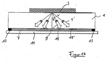
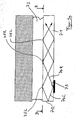
- Fig. 1a 1 denotes a substrate, e.g. B. made of glass. Possible is z. B. the use of a slide. 5 is a piezoelectric crystal element, e.g. B. from lithium niobate. Between the piezoelectric crystal element 5 and the glass body 1 is an interdigital transducer 3, the z. B. was applied in advance on the piezoelectric crystal 5.
- An interdigital transducer is typically formed of comb-like interdigitated metallic electrodes whose double finger spacing defines the wavelength of a surface acoustic wave generated by applying a high frequency alternating field (in the range of, for example, a few MHz to several hundred MHz) to the interdigital transducer in the piezoelectric crystal be stimulated.
- a high frequency alternating field in the range of, for example, a few MHz to several hundred MHz
- surface acoustic wave should also include interfacial waves at the interface between piezoelectric element 5 and substrate 1.
- Such Interdigital transducers are in DE-A-101 17 772 described and known from surface wave filter technology.
- For connecting the electrodes of the Interdigitaitransducers serve metallic leads 16, which lead to a high-frequency source, not shown.
- the substrate 1 is via spacers 13 on a further substrate 11, for. B. also stored a glass slide.
- the spacers may be separate elements or integrally molded with one of the substrates 1, 11.
- Between the substrates 1 and 11 is a liquid film 7, which is to be mixed.
- the capillary gap, in which the liquid is 7, is a few micrometers, z. 30 to several 100 microns.
- the spots has in a regular arrangement, where different macromolecules are bound.
- the liquid 7 z. B. other macromolecules present whose reaction properties to be examined with the macromolecules of the microarray.
- the ultrasonic wave generating device is arranged on the liquid film opposite side of the substrate 1.
- the ultrasonic wave generating device may also be arranged on the side of the other substrate 11 opposite the liquid film.
- ultrasonic waves 9 can be generated in the specified direction, which as described above at an angle ⁇ to the normal of the substrate 1 as a volume sound wave pass through the substrate 1. 15, those areas of the interface between the liquid 7 and the substrate 1 are schematically indicated, which are substantially affected by the volume sound wave 9.
- the exit sites 15 of the sound wave in the liquid a distance of about 8 mm and are arranged symmetrically to the sound source. If the interdigital transducer is operated at a high frequency power of 500 mW, the range is about 5 mm, which is sufficient for mixing a liquid in a capillary gap over a microarray on the substrate 11 an area of 0.8 to 1.25 cm 2 .
- FIG. 1 b serves for explanation in order to show how, with an embodiment of FIG. 1 a, different coupling-in angles can be set by selecting different frequencies.
- FIG. 2 shows a sectional view in the direction of view A according to the indication in FIG. 1.
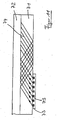
- FIG. 3 shows an alternative design.
- the interdigital transducer on the piezoelectric crystal 5 is connected to a side surface of the substrate 1.
- a volume sound wave 9 is radiated into the substrate 1 at an angle when a high-frequency voltage is applied to the interdigital transducer.
- the electrodes necessary for this purpose are not shown separately in FIG. 3 for the sake of clarity.
- the portion of the volume sound wave blasted in the direction of the capillary gap with the liquid 7 strikes directly at the interface between substrate 1 and liquid film 7.
- the volume sound wave emitted upward in FIG. 3 is at least partially reflected at the surface of substrate 1 in direction 17 and impinges elsewhere on the interface between liquid film 7 and substrate. 1
- FIG. 4 shows an embodiment in which the interdigital transducer 3 is not arranged at the interface between the substrate 1 and the piezoelectric crystal 5, but rather on the side of the piezoelectric crystal 5 facing away from the substrate 1.
- FIG. 5 shows an embodiment in which the piezoelectric crystal 5 is connected to the interdigital transducer 3 via a coupling medium 19 for secure and full-surface coupling to the substrate 1.
- a coupling medium z.
- the coupling medium can increase the efficiency of the sound generation in the substrate 1 with a suitable design (thickness, material).
- a thin coupling layer influences the angle ⁇ only negligibly.
- Such a coupling medium can be used in all process guides.
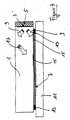
- the electrical contacting of the interdigital transducer electrode in the embodiments of Figures 1, 2, 3 and 5 is shown schematically in Figure 6 in three different embodiments.
- metallic interconnects are applied to the substrate (on the back or for the embodiment of Figure 3 frontally).
- the piezoelectric transducer 5 is placed on the substrate so as to overlap the metallic electrode on the substrate with an electrode of the interdigital transducer on the piezoelectric transducer.
- bonding the piezoelectric transducer to the substrate is glued in the overlap region with electrically conductive adhesive, whereas the remaining surface is glued with conventional non-electrically conductive adhesive.
- the electrical contact 22 of the metallic interconnects on the substrate in Direction high frequency generator electronics is done by a solder joint, an adhesive connection or a spring contact pin.
- the contact 22 sets directly on the applied on the piezoelectric transducer electrical leads 16.
- the contact can be soldered, glued, bonded or done by means of a spring contact pin.
- the substrate 1 is provided with a hole 23 per electrical contact and the piezoelectric transducer 5 is placed on the substrate 1, that applied to the piezoelectric transducer electrical supply lines can be contacted through the holes 23 therethrough.
- the electrical contact can be made in this case by a spring contact pin directly on the electrical leads on the piezoelectric transducer 5.
- Another possibility is to fill the hole with a conductive adhesive 23 or glue it to a metallic bolt. The further contacting 22 in the direction of high-frequency generator electronics is then done by a solder joint, another adhesive connection or a spring contact pin.
- the electrical leads to the interdigital transducer electrodes are formed such that they serve as an antenna for contactless control of the high-frequency signal.
- this is an annular electrode on the piezoelectric transducer, which serves as a secondary circuit of a high-frequency transformer whose primary circuit with the high-frequency generator electronics connected is. This is kept external and is mounted directly adjacent to the piezoelectric transducer.
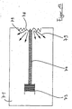
- Figure 7 shows the use of a piezoelectric volume vibrator, z. B. a piezoelectric thickness vibrator 30 which is arranged such that an oblique coupling of a sound wave takes place.
- a so-called wedge transducer is used, which is connected to a high-frequency source 31.
- the angle ⁇ can also be 90 °.
- the sounder 300 is disposed on an end face of the substrate 1. This arrangement of the sounder 300 is indicated by dashed lines in Figure 7.
- FIG. 7 Not shown in FIG. 7 are spacers between the substrate 1 and the second substrate 11 for producing the capillary gap, in which the liquid 7 is present. Both in this embodiment and in the embodiments of FIGS. 1 to 5, such a microarray may be located on the substrate 1 or the substrate 11.
- a microarray 21 is indicated in FIG. 7 in order to illustrate one of the possible applications of a mixing device or of the mixing method.
- the microarray 21 includes spots in a regular arrangement, for. B. in matrix form, which are functionalized to z. B. to react with macromolecules in the liquid 7.
- the piezoelectric element 5 is pressed firmly against the substrate 1.
- the substrate 11 may be provided with a microarray. Thereafter, a substrate 1 with a surface acoustic wave generation device is placed over spacers 13, as shown in Figures 1 to 4.
- the liquid 7 can be transported in the capillary gap. The liquid spreads substantially independently in the gap due to capillary forces.
- the liquid can also be applied to the substrate 11 in advance.
- Application of a high-frequency electric field to the interdigital transducer 3 generates interfacial sound waves at the interface between the piezoelectric crystal 5 and the substrate, which lead to the excitation of volume sound waves 9 in the substrate 1.
- the volume sound wave 9 propagates in the substrate 1 in the directions indicated in FIGS. 1 to 4.
- FIG. 1b shows how a device of FIG. 1a can be used for the direct excitation of volume modes in order to adjust the location of the coupling into the liquid film by varying the excitation frequency.
- the substrate 1, the liquid 7 and the substrate 11 are prepared in the manner described. Only then is the piezoelectric crystal 5 placed on the coupling medium 19 with the interdigital transducer 3. Then, a high-frequency field is applied to the interdigital transducer 3 in the manner described in order to produce a volume wave 9 in the substrate 1.
- the microarray 21 is exemplarily located on the substrate 1.
- Application of a high-frequency field to the piezoelectric sounder 30 generates an oblique volume sound wave in the substrate 1, which strikes the interface between liquid film 7 and substrate 1.
- an impulse transfer takes place on the liquid film 7 or material contained therein, in order to conduct there for thorough mixing or homogenization.
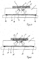
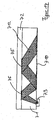
- Figure 8 shows an embodiment in which a substrate 71 is used, which has a low acoustic attenuation for the ultrasonic frequencies used.
- a substrate 71 which has a low acoustic attenuation for the ultrasonic frequencies used.
- quartz glass preferably 100 MHz to 250 MHz, can be used.
- a volume sound wave 74 which enters the substrate obliquely, is generated. This strikes the interface between substrate 71 and liquid 72 at points 75.
- Appropriate selection of the substrate material 71 causes a portion of the ultrasonic wave 74 to be reflected at points 75 and 76, respectively, and another portion to be decoupled.
- the thickness of the substrate in this way, the points 75, at which a part of the ultrasonic wave from the substrate 71 is coupled into the liquid 72, are determined locally precisely, and in this way a desired movement pattern in the liquid 72 are generated.
- a flow can be generated in this way, which is adapted to move the fluid in one direction.
- Figure 8 can in this way, for. B. a flow in a fluid along the direction of sound shown in direction 711 are induced, with the aid of which, for example, a dye in about 100 seconds over a distance of 40 mm in the fluid can be moved.
- a dye in about 100 seconds over a distance of 40 mm in the fluid can be moved.
- Figure 9 shows a variation of the arrangement of Figure 8.
- Figure 9a is a side sectional view is shown. From the bidirectionally emitting interdigital transducer 73, a beam 74L goes to the left in FIG. 9 and a beam 74R to the right into the substrate 71. At the edge 712 of the substrate 71, the sound beam 74L is reflected and toward the interface between substrate 71 and liquid 72 distracted. He hits the interface for the first time at point 75L. The sound beam 74R strikes the interface at location 75R. In this way, the density of Einkoppelrelates can be increased. This is shown schematically once again in FIG. 9b in the viewing direction B of FIG. 9a.
- FIG. 10 a shows a plan view of a cross-section of an arrangement, approximately at the level of the interface between liquid 72 and substrate 71, which enables a special steering of the sound beam in the substrate 71.
- FIG. 10b shows an arrangement with which it can be achieved that a planar substrate can be covered almost completely with the aid of only one bidirectionally emitting interdigital transducer 73 in this manner, this being achieved by means of multiple reflections on the side surfaces 77 of the substrate 71 ,
- the reflection points on the main surface of the substrate 71 are not shown for the sake of clarity, but only the direction of propagation of the ultrasound waves 74 caused by reflections on the major surfaces of the substrate 71, such as, for example, FIG. B. described with reference to Figure 8a, is effected.
- FIG. 11 shows, as a lateral section, an arrangement in which the beam cross section is effectively broadened by using a plurality of interdigital transducers 73 to generate parallel beam bundles 74.
- sound can be coupled more homogeneously into the liquid 72 of the capillary gap, which is favorable for a long-range fluidic flow in the capillary gap, in which fluids are to be transported over long distances.
- the described reflection effect by selecting a suitable substrate material can also be generated by means of a volume oscillator 83, as shown in FIG.
- the oblique coupling at the angle ⁇ takes place as described with reference to FIG.
- the sound exit points for the sound beam 84 from the substrate 71 into the liquid 72 are indicated at 85 in FIG.
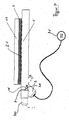
- FIG. 13 shows an embodiment in which an edge 78 of the substrate 71 is roughened in order to produce a diffuse reflection of the incident sound wave 74. This can be useful to disable an unwanted sound beam reflected at an edge. Again, only the entire propagation direction of the beam 74, which is caused by the reflection of the sound wave at the main surfaces of the substrate 71, is indicated in FIG.
- FIG. 14 shows an embodiment in which the back surface 710 of the substrate 71 is roughened.
- the interdigital transducer 73 is located on this rear surface.
- the beam 712 is widened by diffraction due to the roughened surface. This effect is further enhanced with further reflections on surface 710.
- the coupling point is widened accordingly.
- the expansion of the sound beam 713 after coupling from the interdigital transducer 73 into the substrate 71 is achieved by reflection at a curved reflection edge 711.
- focusing can be achieved with the aid of a suitably designed reflection edge.
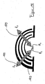
- FIG. 16 shows a further embodiment in a schematic representation.
- only a few interdigitated fingers of the interdigital transducer 103 are shown here for the sake of clarity, although a realized interdigital transducer has a larger number of finger electrodes has.
- the spacing of the individual finger electrodes of the interdigital transducer 103 is not constant.
- the interdigital transducer 103 therefore radiates at a high frequency fed only at a location where the finger spacing correlates with the frequency, as it is for another application z.
- WO 01/20781 A1 is described.
- the finger electrodes are also not straight, but arcuate. Since the interdigital transducer radiates essentially perpendicular to the orientation of the fingers, the direction of the radiated surface acoustic wave can be azimuthally controlled in this way by selecting the supplied high frequency.
- FIG. 16 shows, by way of example, the emission directions 109 for two frequencies f1 and f2, where, at the frequency f1, the emission direction is indicated by the angle ⁇ 1 and for the frequency f2 by the angle ⁇ 2 .
- FIG. 16 shows, by way of example, the emission directions 109 for two frequencies f1 and f2, where, at the frequency f1, the emission direction is indicated by the angle ⁇ 1 and for the frequency f2 by the angle ⁇ 2 .
- FIG. 16 shows schematically again the top view of the interface between the piezoelectric substrate on which the interdigital transducer 103 is applied and the substrate separating the interdigital transducer from the liquid film to be moved, analogous to e.g. B. the cross-section AA, as indicated for the embodiment of Figure 1 in Figure 1.
Landscapes
- Chemical & Material Sciences (AREA)
- Health & Medical Sciences (AREA)
- Chemical Kinetics & Catalysis (AREA)
- Clinical Laboratory Science (AREA)
- General Health & Medical Sciences (AREA)
- Hematology (AREA)
- Analytical Chemistry (AREA)
- Dispersion Chemistry (AREA)
- Transducers For Ultrasonic Waves (AREA)
- Application Of Or Painting With Fluid Materials (AREA)
- Coating Apparatus (AREA)
- Micromachines (AREA)
- Investigating Or Analyzing Materials By The Use Of Ultrasonic Waves (AREA)
Claims (26)
- Procédé pour générer un mouvement dans un film liquide mince en contact avec un substrat (1, 71), en particulier dans un intervalle capillaire, par l'intermédiaire d'un dispositif selon la revendication 13, dans lequel- on envoie au moins une onde d'ultrasons (9, 17, 74, 84, 109, 712, 713) à travers le substrat (1, 71) en direction du film liquide (7, 72),- les ultrasons (9, 17, 74, 84, 109, 712, 713) générés par au moins un dispositif générateur d'ultrasons (3, 73) sont injectés dans le film liquide (7) de telle sorte que le liquide est mis en mouvement à au moins deux pôles de mouvement (15, 75, 85) par l'énergie ultrasonique générée par le dispositif générateur d'ultrasons, et- le film liquide (7, 72) présente une épaisseur de quelques µm jusqu'à 5 mm, de préférence jusqu'à quelques centaines de µm, dans le sens de la direction de propagation de l'onde d'ultrasons.
- Procédé pour générer un mouvement dans un film liquide mince selon la revendication 1, dans lequel ladite au moins une onde d'ultrasons (9, 17, 74, 84, 109, 712, 713) traverse le substrat en oblique par rapport au plan du film liquide (7, 72).
- Procédé pour générer un mouvement dans un film liquide mince selon la revendication 2, dans lequel on utilise à titre de dispositif générateur d'ultrasons un dispositif générateur d'ultrasons à rayonnement bidirectionnel, de préférence un transducteur interdigital (3, 73).
- Procédé pour générer un mouvement dans un film liquide mince selon l'une des revendications 1 à 3, dans lequel on injecte une onde d'ultrasons (74, 84) dans le substrat (71) de manière à être réfléchie au moins une fois à l'intérieur du substrat, en utilisant un substrat dans lequel la réflexion sur la surface limite détournée du liquide est le plus possible totale, et celle sur la surface limite tournée vers le liquide est affectée d'une perte, mais inégale à 0, et la perte à l'intérieur du substrat est aussi faible que possible.
- Procédé selon l'une des revendications 1 à 4, dans lequel lesdits au moins deux pôles de mouvement différents (15, 15') sont générés par variation temporelle de la direction de rayonnement (α, α', θ, θ') dudit au moins un dispositif générateur d'ultrasons (3).
- Procédé pour générer un mouvement dans un film liquide mince selon l'une des revendications 1 à 5, dans lequel ladite au moins une onde d'ultrasons est générée à l'aide d'un transducteur interdigital (103) sur un élément piézoélectrique dans lequel les électrodes à doigts mutuellement engagées du transducteur interdigital présentent une distance non constante dans l'espace, et en ce que l'on règle l'endroit de rayonnement et donc l'endroit d'injection de l'onde d'ultrasons dans le film liquide par modification de la fréquence qui s'applique au transducteur interdigital.
- Procédé pour générer un mouvement dans un film liquide mince selon la revendication 6, dans lequel on utilise un transducteur interdigital (103) dont les électrodes à doits mutuellement engagées ne sont pas linéaires, mais en particulier en forme d'arc, et en ce que l'on choisit la direction de rayonnement et ainsi l'endroit d'injection de l'onde d'ultrasons dans le film liquide par le choix de la fréquence du champ à haute fréquence appliqué.
- Procédé pour générer un mouvement dans un film liquide mince selon l'une des revendications 1 à 7, dans lequel ladite au moins une onde d'ultrasons (9, 74, 109, 712, 713) est générée à l'aide d'un élément générateur d'onde en surface, de préférence un transducteur interdigital (3, 73, 103) sur un élément piézoélectrique (5) sur le côté du substrat (1, 71) détourné du film liquide (7, 72).
- Procédé pour générer un mouvement dans un film liquide mince selon l'une des revendications 1 à 7, dans lequel ladite au moins une onde d'ultrasons (9) est générée à l'aide d'un élément générateur d'onde en surface (3), de préférence un transducteur interdigital (3) sur un élément piézoélectrique (5) sur une surface frontale du substrat (1).
- Procédé pour générer un mouvement dans un film liquide mince selon l'une des revendications 1 à 9, dans lequel on utilise un substrat (71) qui comprend au moins une surface (78, 710) à dispersion diffuse pour élargir ladite au moins une onde d'ultrasons (74, 712) dans le substrat.
- Procédé pour générer un mouvement dans un film liquide mince selon l'une des revendications 1 à 10, dans lequel la direction de propagation de ladite au moins une onde d'ultrasons (74) dans le substrat (71) est dirigée par des surfaces de réflexion (77) qui font partie de surfaces frontales du substrat (71).
- Procédé pour générer un mouvement dans un film liquide mince selon l'une des revendications 1 à 11, dans lequel l'onde d'ultrasons présente une fréquence dans la plage de quelques MHz jusqu'à quelques centaines de MHz.
- Dispositif pour générer un mouvement dans un film liquide mince d'une épaisseur de quelques micromètres jusqu'à 5 mm pour mettre en oeuvre un procédé selon la revendication 1, comportant un substrat (1, 71) avec deux surfaces principales dont l'une sert au contact avec le film liquide (7, 72) et au moins un dispositif générateur d'onde d'ultrasons (3, 73) en contact avec le substrat, le film liquide étant séparé dudit au moins un dispositif générateur d'ultrasons (3, 73) par le substrat, caractérisé en ce que le dispositif générateur d'onde d'ultrasons est conçu de telle sorte qu'au moins une onde d'ultrasons (9, 17, 74, 84, 109, 712, 713) est injectée en oblique dans le substrat.
- Dispositif pour générer un mouvement dans un film liquide mince (7, 72) selon la revendication 13, dans lequel ledit au moins un élément générateur d'onde d'ultrasons (3, 30, 73, 103) est agencé sur une surface principale du substrat (1, 71) qui est opposée à cette surface principale qui sert au contact avec le film liquide (7, 72).
- Dispositif pour générer un mouvement dans un film liquide mince (7) selon la revendication 13, dans lequel ledit au moins un élément générateur d'onde d'ultrasons (3, 30) est agencé sur une surface frontale du substrat (1), qui n'est pas une surface principale.
- Dispositif pour générer un mouvement dans un film liquide mince selon l'une des revendications 13 à 15, dans lequel ledit au moins un élément générateur d'onde d'ultrasons convient pour générer une fréquence de quelques MHz jusqu'à quelques centaines de MHz.
- Dispositif selon l'une des revendications 13 à 16, dans lequel ledit au moins un dispositif générateur d'onde d'ultrasons (3, 73) est à rayonnement bidirectionnel.
- Dispositif selon l'une des revendications 13 à 17, dans lequel le matériau du substrat (71) est choisi de telle sorte que les réflexions sur la surface limite détournée du liquide est le plus possible totale, et les réflexions sur le côté tourné vers le liquide sont affectées d'une perte, mais inégales à 0, et la perte d'intensité ultrasonique à l'intérieur du substrat est aussi faible que possible.
- Dispositif pour générer un mouvement dans un film liquide mince selon l'une des revendications 13 à 18, dans lequel ledit au moins un élément générateur d'onde d'ultrasons (3, 73, 103) comprend un transducteur interdigital (3, 73, 103) sur un élément piézoélectrique (5).
- Dispositif pour générer un mouvement dans un film liquide mince selon la revendication 19, dans lequel le raccordement électrique dudit au moins un transducteur interdigital (3) est formé par une première ligne d'alimentation sur l'élément piézoélectrique (5) et par une seconde ligne d'alimentation sur le substrat (1), qui sont agencées de manière à chevaucher l'une avec l'autre.
- Dispositif pour générer un mouvement dans un film liquide mince selon la revendication 19, dans lequel l'élément piézoélectrique (5) présente un porte-à-faux au-dessus du substrat (1), sur lequel se trouve un emplacement de contact pour la ligne d'alimentation électrique (16) vers ledit au moins un transducteur interdigital (3).
- Dispositif pour générer un mouvement dans un film liquide mince selon la revendication 19, dans lequel ledit au moins un transducteur interdigital (3) est mis en contact à travers un trou à travers le substrat (1), qui est de préférence rempli d'une colle conductrice (23).
- Dispositif pour générer un mouvement dans un film liquide mince selon la revendication 19, dans lequel le transducteur interdigital (3) dispose de moyens formant antenne qui sont utilisables pour l'injection sans contact d'un signal haute fréquence.
- Dispositif pour générer un mouvement dans un film liquide mince selon l'une des revendications 19 à 23, dans lequel les électrodes à doigts du transducteur interdigital (103) ne présentent pas de distance constante dans l'espace les unes des autres.
- Dispositif pour générer un mouvement dans un film liquide mince selon la revendication 24, dans lequel les électrodes à doigts du transducteur interdigital (103) ne sont pas rectilignes, mais conçues en particulier en forme d'arc.
- Dispositif pour générer un mouvement dans un film liquide mince selon l'une des revendications 13 à 25, dans lequel le substrat (71) présente au moins une surface (78, 710) à dispersion diffuse.
Applications Claiming Priority (7)
| Application Number | Priority Date | Filing Date | Title |
|---|---|---|---|
| DE10308622 | 2003-02-27 | ||
| DE10308622 | 2003-02-27 | ||
| DE10309183 | 2003-03-03 | ||
| DE10309183 | 2003-03-03 | ||
| DE10325313 | 2003-06-04 | ||
| DE10325313A DE10325313B3 (de) | 2003-02-27 | 2003-06-04 | Verfahren und Vorrichtung zur Erzeugung von Bewegung in einem dünnen Flüssigkeitsfilm |
| PCT/EP2004/000688 WO2004076047A1 (fr) | 2003-02-27 | 2004-01-27 | Procede et dispositif permettant de generer un mouvement dans une pellicule liquide de faible epaisseur |
Publications (2)
| Publication Number | Publication Date |
|---|---|
| EP1596972A1 EP1596972A1 (fr) | 2005-11-23 |
| EP1596972B1 true EP1596972B1 (fr) | 2008-01-09 |
Family
ID=32930934
Family Applications (1)
| Application Number | Title | Priority Date | Filing Date |
|---|---|---|---|
| EP04705396A Expired - Lifetime EP1596972B1 (fr) | 2003-02-27 | 2004-01-27 | Procede et dispositif permettant de generer un mouvement dans une pellicule liquide de faible epaisseur |
Country Status (4)
| Country | Link |
|---|---|
| US (1) | US20070264161A1 (fr) |
| EP (1) | EP1596972B1 (fr) |
| AT (1) | ATE383197T1 (fr) |
| WO (1) | WO2004076047A1 (fr) |
Families Citing this family (11)
| Publication number | Priority date | Publication date | Assignee | Title |
|---|---|---|---|---|
| DE502004004027D1 (de) * | 2003-02-27 | 2007-07-19 | Advalytix Ag | Verfahren und vorrichtung zur durchmischung kleiner flüssigkeitsmengen in mikrokavitäten |
| DE102004051394B4 (de) * | 2004-10-21 | 2006-08-17 | Advalytix Ag | Verfahren zur Bewegung von kleinen Flüssigkeitsmengen in Mikrokanälen und Mikrokanalsystem |
| WO2007043261A1 (fr) * | 2005-10-14 | 2007-04-19 | Olympus Corporation | Dispositif de brassage, contenant et dispositif d'analyse |
| JP2007178408A (ja) * | 2005-12-28 | 2007-07-12 | Olympus Corp | 反応容器及び分析装置 |
| WO2007088673A1 (fr) * | 2006-01-31 | 2007-08-09 | Olympus Corporation | dispositif de détection de position, procédé de détection de position et dispositif d'analyse |
| GB0914762D0 (en) * | 2009-08-24 | 2009-09-30 | Univ Glasgow | Fluidics apparatus and fluidics substrate |
| FR2955508B1 (fr) | 2010-01-25 | 2012-03-30 | Corning Inc | Microreacteurs avec dispositif microfluidique plan et systeme d'application d'ultrasons ; mise en oeuvre de reactions chimiques en leur sein |
| EP2638381B1 (fr) | 2010-11-10 | 2018-09-05 | Roche Diagnostics Hematology, Inc. | Dispositif automatisé pour préparer des échantillons biologiques à examiner |
| GB201103211D0 (en) * | 2011-02-24 | 2011-04-13 | Univ Glasgow | Fluidics apparatus, use of fluidics apparatus and process for the manufacture of fluidics apparatus |
| ES2939124T3 (es) | 2013-04-05 | 2023-04-19 | Roche Diagnostics Hematology Inc | Sistemas y procedimientos automatizados para preparar muestras biológicas para su examen |
| GB201420061D0 (en) | 2014-11-11 | 2014-12-24 | Univ Glasgow | Nebulisation of liquids |
Family Cites Families (43)
| Publication number | Priority date | Publication date | Assignee | Title |
|---|---|---|---|---|
| US2420864A (en) * | 1943-04-17 | 1947-05-20 | Chilowsky Constantin | Piezoelectric plastic material and method of making same |
| NL6511135A (fr) * | 1965-08-26 | 1967-02-27 | ||
| US3433461A (en) * | 1967-05-22 | 1969-03-18 | Edison Instr Inc | High-frequency ultrasonic generators |
| US3575383A (en) * | 1969-01-13 | 1971-04-20 | John A Coleman | Ultrasonic cleaning system, apparatus and method therefor |
| US3665225A (en) * | 1970-08-28 | 1972-05-23 | Iit Res Inst | Hybrid surface-wave transducer |
| US3745812A (en) * | 1971-07-07 | 1973-07-17 | Zenith Radio Corp | Acoustic imaging apparatus |
| US3727718A (en) * | 1971-11-24 | 1973-04-17 | Us Navy | Surface wave ambiguity analyzer |
| DE2742492C3 (de) * | 1977-03-24 | 1984-07-19 | Kohji Yokosuka Kanagawa Toda | Ultraschallwandler |
| JPS5822915B2 (ja) * | 1978-08-21 | 1983-05-12 | ティーディーケイ株式会社 | 超音波トランスデュ−サ |
| US4691982A (en) * | 1984-03-10 | 1987-09-08 | Canon Kabushiki Kaisha | Optical coupler |
| CA1246891A (fr) * | 1984-06-13 | 1988-12-20 | Alan M. Smith | Instruments photometriques, leur emploi en analyse optique, et leurs accessoires |
| JPH0660896B2 (ja) * | 1984-11-02 | 1994-08-10 | 株式会社日立製作所 | 超音波探触子 |
| US4697195A (en) * | 1985-09-16 | 1987-09-29 | Xerox Corporation | Nozzleless liquid droplet ejectors |
| US4908542A (en) * | 1987-06-24 | 1990-03-13 | Unisys | Saw tapered transducers |
| US4746882A (en) * | 1987-06-24 | 1988-05-24 | Unisys Corporation | Saw multiplexer using tapered transducers |
| GB8911462D0 (en) * | 1989-05-18 | 1989-07-05 | Ares Serono Res & Dev Ltd | Devices for use in chemical test procedures |
| US5006749A (en) * | 1989-10-03 | 1991-04-09 | Regents Of The University Of California | Method and apparatus for using ultrasonic energy for moving microminiature elements |
| WO1994002911A1 (fr) * | 1992-07-24 | 1994-02-03 | Toda Koji | Systeme a ultrasons reagissant au toucher |
| US5639423A (en) * | 1992-08-31 | 1997-06-17 | The Regents Of The University Of Calfornia | Microfabricated reactor |
| US5919712A (en) * | 1993-05-18 | 1999-07-06 | University Of Utah Research Foundation | Apparatus and methods for multi-analyte homogeneous fluoro-immunoassays |
| US5512492A (en) * | 1993-05-18 | 1996-04-30 | University Of Utah Research Foundation | Waveguide immunosensor with coating chemistry providing enhanced sensitivity |
| US5736100A (en) * | 1994-09-20 | 1998-04-07 | Hitachi, Ltd. | Chemical analyzer non-invasive stirrer |
| US6168948B1 (en) * | 1995-06-29 | 2001-01-02 | Affymetrix, Inc. | Miniaturized genetic analysis systems and methods |
| JP3487699B2 (ja) * | 1995-11-08 | 2004-01-19 | 株式会社日立製作所 | 超音波処理方法および装置 |
| US6720710B1 (en) * | 1996-01-05 | 2004-04-13 | Berkeley Microinstruments, Inc. | Micropump |
| AU1358697A (en) * | 1996-01-05 | 1997-08-01 | Berkeley Microinstruments, Inc. | Micropump with sonic energy generator |
| US6010316A (en) * | 1996-01-16 | 2000-01-04 | The Board Of Trustees Of The Leland Stanford Junior University | Acoustic micropump |
| JPH1154471A (ja) * | 1997-08-05 | 1999-02-26 | Tokyo Electron Ltd | 処理装置及び処理方法 |
| JPH11347392A (ja) * | 1998-06-11 | 1999-12-21 | Hitachi Ltd | 攪拌装置 |
| US6948843B2 (en) * | 1998-10-28 | 2005-09-27 | Covaris, Inc. | Method and apparatus for acoustically controlling liquid solutions in microfluidic devices |
| US6210128B1 (en) * | 1999-04-16 | 2001-04-03 | The United States Of America As Represented By The Secretary Of The Navy | Fluidic drive for miniature acoustic fluidic pumps and mixers |
| US6357907B1 (en) * | 1999-06-15 | 2002-03-19 | V & P Scientific, Inc. | Magnetic levitation stirring devices and machines for mixing in vessels |
| US6777245B2 (en) * | 2000-06-09 | 2004-08-17 | Advalytix Ag | Process for manipulation of small quantities of matter |
| AU2001292997A1 (en) * | 2000-09-30 | 2002-04-15 | Aviva Biosciences Corporation | Apparatuses containing multiple force generating elements and uses thereof |
| DE10062246C1 (de) * | 2000-12-14 | 2002-05-29 | Advalytix Ag | Verfahren und Vorrichtung zur Manipulation kleiner Flüssigkeitsmengen |
| DE10117772C2 (de) * | 2001-04-09 | 2003-04-03 | Advalytix Ag | Mischvorrichtung und Mischverfahren für die Durchmischung kleiner Flüssigkeitsmengen |
| DE10142789C1 (de) * | 2001-08-31 | 2003-05-28 | Advalytix Ag | Bewegungselement für kleine Flüssigkeitsmengen |
| US20040105476A1 (en) * | 2002-08-19 | 2004-06-03 | Wasserbauer John G. | Planar waveguide surface emitting laser and photonic integrated circuit |
| GB0221391D0 (en) * | 2002-09-16 | 2002-10-23 | Secr Defence | Apparatus for directing particles in a fluid |
| WO2004112093A2 (fr) * | 2003-06-06 | 2004-12-23 | P.C.T. Systems, Inc. | Procedes et appareil pour traiter des substrats avec de l'energie megasonique |
| JP4365813B2 (ja) * | 2004-09-22 | 2009-11-18 | オリンパス株式会社 | 攪拌装置、容器および攪拌装置を備えた分析装置 |
| US7287431B2 (en) * | 2005-04-14 | 2007-10-30 | Honeywell International Inc. | Wireless oil filter sensor |
| JP2007232522A (ja) * | 2006-02-28 | 2007-09-13 | Olympus Corp | 攪拌装置と分析装置 |
-
2004
- 2004-01-27 US US10/547,263 patent/US20070264161A1/en not_active Abandoned
- 2004-01-27 EP EP04705396A patent/EP1596972B1/fr not_active Expired - Lifetime
- 2004-01-27 AT AT04705396T patent/ATE383197T1/de not_active IP Right Cessation
- 2004-01-27 WO PCT/EP2004/000688 patent/WO2004076047A1/fr active IP Right Grant
Also Published As
| Publication number | Publication date |
|---|---|
| EP1596972A1 (fr) | 2005-11-23 |
| ATE383197T1 (de) | 2008-01-15 |
| WO2004076047A1 (fr) | 2004-09-10 |
| US20070264161A1 (en) | 2007-11-15 |
Similar Documents
| Publication | Publication Date | Title |
|---|---|---|
| EP1596974B1 (fr) | Procede et dispositif pour melanger de petites quantites de liquide dans des microcavites | |
| DE10325307B3 (de) | Verfahren und Vorrichtung zur Durchmischung kleiner Flüssigkeitsmengen in Mikrokavitäten | |
| EP1286774B1 (fr) | Dispositif et procede permettant de manipuler de petites quantites de matiere | |
| US8303778B2 (en) | Method and device for generating movement in a thin liquid film | |
| EP1596972B1 (fr) | Procede et dispositif permettant de generer un mouvement dans une pellicule liquide de faible epaisseur | |
| DE19820466C2 (de) | Vorrichtung und Verfahren zur gezielten Beaufschlagung einer biologischen Probe mit Schallwellen | |
| DE2915761A1 (de) | Vorrichtung zur ultraschall-untersuchung eines objektes | |
| EP1781410B1 (fr) | Procede pour deplacer de petites quantites de liquide dans des microcanaux au moyen d'ondes acoustiques | |
| EP0041664A1 (fr) | Procédé de fabrication d'un agencement d'un transducteur ultrasonique | |
| WO2002082053A2 (fr) | Procede et dispositif pour manipuler de faibles quantites de liquide et/ou des particules contenues dans ce liquide | |
| EP1409722B1 (fr) | Procede d'analyse de macromolecules | |
| EP1345696A1 (fr) | Procede et dispositif de manipulation de petites quantites de liquides | |
| DE10055318A1 (de) | Vorrichtung und Verfahren zum Materietransport kleiner Materiemengen | |
| EP0472085B1 (fr) | Capteur d'ultrason | |
| EP1337998A1 (fr) | Transducteur d'ultrasons et debitmetre a ultrasons | |
| WO2019001760A1 (fr) | Dispositif de mesure et procédé servant à déterminer une grandeur fluidique | |
| EP4056960B1 (fr) | Convertisseur ultrasonique permettant d'émettre et/ou de recevoir des ondes ultrasoniques | |
| DE19928765A1 (de) | Ultraschallwandleranordnung und Verfahren zur Ultraschallprüfung | |
| DE3024457A1 (de) | Ultraschallpruefkopf | |
| DE10141148B4 (de) | Mikrodispenser | |
| DE202021101237U1 (de) | Ultraschallwandler zum Senden und/oder Empfangen von Ultraschallwellen | |
| EP3910297A1 (fr) | Procédé d'excitation sélective de mode d'une onde guidée et dispositif de mesure | |
| DE102017215535A1 (de) | Verpackungsanlage |
Legal Events
| Date | Code | Title | Description |
|---|---|---|---|
| PUAI | Public reference made under article 153(3) epc to a published international application that has entered the european phase |
Free format text: ORIGINAL CODE: 0009012 |
|
| 17P | Request for examination filed |
Effective date: 20050824 |
|
| AK | Designated contracting states |
Kind code of ref document: A1 Designated state(s): AT BE BG CH CY CZ DE DK EE ES FI FR GB GR HU IE IT LI LU MC NL PT RO SE SI SK TR |
|
| AX | Request for extension of the european patent |
Extension state: AL LT LV MK |
|
| DAX | Request for extension of the european patent (deleted) | ||
| RIN1 | Information on inventor provided before grant (corrected) |
Inventor name: RATHGEBER, ANDREAS Inventor name: WASSERMEIER, MATTHIAS |
|
| GRAP | Despatch of communication of intention to grant a patent |
Free format text: ORIGINAL CODE: EPIDOSNIGR1 |
|
| RBV | Designated contracting states (corrected) |
Designated state(s): AT BE BG CH CY CZ DK EE ES FI FR GB GR HU IE IT LI LU MC NL PT RO SE SI SK TR |
|
| REG | Reference to a national code |
Ref country code: DE Ref legal event code: 8566 |
|
| GRAS | Grant fee paid |
Free format text: ORIGINAL CODE: EPIDOSNIGR3 |
|
| RIN1 | Information on inventor provided before grant (corrected) |
Inventor name: WASSERMEIER, MATTHIAS Inventor name: RATHGEBER, ANDREAS |
|
| GRAA | (expected) grant |
Free format text: ORIGINAL CODE: 0009210 |
|
| AK | Designated contracting states |
Kind code of ref document: B1 Designated state(s): AT BE BG CH CY CZ DK EE ES FI FR GB GR HU IE IT LI LU MC NL PT RO SE SI SK TR |
|
| REG | Reference to a national code |
Ref country code: GB Ref legal event code: FG4D Free format text: NOT ENGLISH |
|
| REG | Reference to a national code |
Ref country code: CH Ref legal event code: EP |
|
| REG | Reference to a national code |
Ref country code: IE Ref legal event code: FG4D Free format text: LANGUAGE OF EP DOCUMENT: GERMAN |
|
| GBT | Gb: translation of ep patent filed (gb section 77(6)(a)/1977) |
Effective date: 20080122 |
|
| PG25 | Lapsed in a contracting state [announced via postgrant information from national office to epo] |
Ref country code: SI Free format text: LAPSE BECAUSE OF FAILURE TO SUBMIT A TRANSLATION OF THE DESCRIPTION OR TO PAY THE FEE WITHIN THE PRESCRIBED TIME-LIMIT Effective date: 20080109 Ref country code: NL Free format text: LAPSE BECAUSE OF FAILURE TO SUBMIT A TRANSLATION OF THE DESCRIPTION OR TO PAY THE FEE WITHIN THE PRESCRIBED TIME-LIMIT Effective date: 20080109 |
|
| NLV1 | Nl: lapsed or annulled due to failure to fulfill the requirements of art. 29p and 29m of the patents act | ||
| ET | Fr: translation filed | ||
| BERE | Be: lapsed |
Owner name: ADVALYTIX A.G. Effective date: 20080131 |
|
| PG25 | Lapsed in a contracting state [announced via postgrant information from national office to epo] |
Ref country code: FI Free format text: LAPSE BECAUSE OF FAILURE TO SUBMIT A TRANSLATION OF THE DESCRIPTION OR TO PAY THE FEE WITHIN THE PRESCRIBED TIME-LIMIT Effective date: 20080109 Ref country code: ES Free format text: LAPSE BECAUSE OF FAILURE TO SUBMIT A TRANSLATION OF THE DESCRIPTION OR TO PAY THE FEE WITHIN THE PRESCRIBED TIME-LIMIT Effective date: 20080420 |
|
| PG25 | Lapsed in a contracting state [announced via postgrant information from national office to epo] |
Ref country code: BG Free format text: LAPSE BECAUSE OF FAILURE TO SUBMIT A TRANSLATION OF THE DESCRIPTION OR TO PAY THE FEE WITHIN THE PRESCRIBED TIME-LIMIT Effective date: 20080409 Ref country code: MC Free format text: LAPSE BECAUSE OF NON-PAYMENT OF DUE FEES Effective date: 20080131 |
|
| REG | Reference to a national code |
Ref country code: CH Ref legal event code: PL |
|
| PG25 | Lapsed in a contracting state [announced via postgrant information from national office to epo] |
Ref country code: PT Free format text: LAPSE BECAUSE OF FAILURE TO SUBMIT A TRANSLATION OF THE DESCRIPTION OR TO PAY THE FEE WITHIN THE PRESCRIBED TIME-LIMIT Effective date: 20080609 |
|
| REG | Reference to a national code |
Ref country code: IE Ref legal event code: FD4D |
|
| PG25 | Lapsed in a contracting state [announced via postgrant information from national office to epo] |
Ref country code: CH Free format text: LAPSE BECAUSE OF NON-PAYMENT OF DUE FEES Effective date: 20080131 Ref country code: LI Free format text: LAPSE BECAUSE OF NON-PAYMENT OF DUE FEES Effective date: 20080131 Ref country code: CZ Free format text: LAPSE BECAUSE OF FAILURE TO SUBMIT A TRANSLATION OF THE DESCRIPTION OR TO PAY THE FEE WITHIN THE PRESCRIBED TIME-LIMIT Effective date: 20080109 Ref country code: DK Free format text: LAPSE BECAUSE OF FAILURE TO SUBMIT A TRANSLATION OF THE DESCRIPTION OR TO PAY THE FEE WITHIN THE PRESCRIBED TIME-LIMIT Effective date: 20080109 Ref country code: SK Free format text: LAPSE BECAUSE OF FAILURE TO SUBMIT A TRANSLATION OF THE DESCRIPTION OR TO PAY THE FEE WITHIN THE PRESCRIBED TIME-LIMIT Effective date: 20080109 Ref country code: IE Free format text: LAPSE BECAUSE OF FAILURE TO SUBMIT A TRANSLATION OF THE DESCRIPTION OR TO PAY THE FEE WITHIN THE PRESCRIBED TIME-LIMIT Effective date: 20080109 Ref country code: SE Free format text: LAPSE BECAUSE OF FAILURE TO SUBMIT A TRANSLATION OF THE DESCRIPTION OR TO PAY THE FEE WITHIN THE PRESCRIBED TIME-LIMIT Effective date: 20080409 |
|
| PLBE | No opposition filed within time limit |
Free format text: ORIGINAL CODE: 0009261 |
|
| STAA | Information on the status of an ep patent application or granted ep patent |
Free format text: STATUS: NO OPPOSITION FILED WITHIN TIME LIMIT |
|
| PG25 | Lapsed in a contracting state [announced via postgrant information from national office to epo] |
Ref country code: RO Free format text: LAPSE BECAUSE OF FAILURE TO SUBMIT A TRANSLATION OF THE DESCRIPTION OR TO PAY THE FEE WITHIN THE PRESCRIBED TIME-LIMIT Effective date: 20080109 |
|
| 26N | No opposition filed |
Effective date: 20081010 |
|
| PG25 | Lapsed in a contracting state [announced via postgrant information from national office to epo] |
Ref country code: EE Free format text: LAPSE BECAUSE OF FAILURE TO SUBMIT A TRANSLATION OF THE DESCRIPTION OR TO PAY THE FEE WITHIN THE PRESCRIBED TIME-LIMIT Effective date: 20080109 |
|
| PG25 | Lapsed in a contracting state [announced via postgrant information from national office to epo] |
Ref country code: BE Free format text: LAPSE BECAUSE OF NON-PAYMENT OF DUE FEES Effective date: 20080131 |
|
| PG25 | Lapsed in a contracting state [announced via postgrant information from national office to epo] |
Ref country code: AT Free format text: LAPSE BECAUSE OF NON-PAYMENT OF DUE FEES Effective date: 20080127 |
|
| PG25 | Lapsed in a contracting state [announced via postgrant information from national office to epo] |
Ref country code: CY Free format text: LAPSE BECAUSE OF FAILURE TO SUBMIT A TRANSLATION OF THE DESCRIPTION OR TO PAY THE FEE WITHIN THE PRESCRIBED TIME-LIMIT Effective date: 20080109 |
|
| PG25 | Lapsed in a contracting state [announced via postgrant information from national office to epo] |
Ref country code: IT Free format text: LAPSE BECAUSE OF FAILURE TO SUBMIT A TRANSLATION OF THE DESCRIPTION OR TO PAY THE FEE WITHIN THE PRESCRIBED TIME-LIMIT Effective date: 20080109 |
|
| PG25 | Lapsed in a contracting state [announced via postgrant information from national office to epo] |
Ref country code: LU Free format text: LAPSE BECAUSE OF NON-PAYMENT OF DUE FEES Effective date: 20080127 Ref country code: HU Free format text: LAPSE BECAUSE OF FAILURE TO SUBMIT A TRANSLATION OF THE DESCRIPTION OR TO PAY THE FEE WITHIN THE PRESCRIBED TIME-LIMIT Effective date: 20080710 |
|
| REG | Reference to a national code |
Ref country code: GB Ref legal event code: 732E Free format text: REGISTERED BETWEEN 20100722 AND 20100728 |
|
| PG25 | Lapsed in a contracting state [announced via postgrant information from national office to epo] |
Ref country code: TR Free format text: LAPSE BECAUSE OF FAILURE TO SUBMIT A TRANSLATION OF THE DESCRIPTION OR TO PAY THE FEE WITHIN THE PRESCRIBED TIME-LIMIT Effective date: 20080109 |
|
| REG | Reference to a national code |
Ref country code: GB Ref legal event code: 732E Free format text: REGISTERED BETWEEN 20100819 AND 20100825 |
|
| PG25 | Lapsed in a contracting state [announced via postgrant information from national office to epo] |
Ref country code: GR Free format text: LAPSE BECAUSE OF FAILURE TO SUBMIT A TRANSLATION OF THE DESCRIPTION OR TO PAY THE FEE WITHIN THE PRESCRIBED TIME-LIMIT Effective date: 20080410 |
|
| REG | Reference to a national code |
Ref country code: FR Ref legal event code: CA Ref country code: FR Ref legal event code: TP |
|
| REG | Reference to a national code |
Ref country code: FR Ref legal event code: PLFP Year of fee payment: 13 |
|
| REG | Reference to a national code |
Ref country code: FR Ref legal event code: PLFP Year of fee payment: 14 |
|
| REG | Reference to a national code |
Ref country code: FR Ref legal event code: PLFP Year of fee payment: 15 |
|
| PGFP | Annual fee paid to national office [announced via postgrant information from national office to epo] |
Ref country code: GB Payment date: 20190128 Year of fee payment: 16 Ref country code: FR Payment date: 20190125 Year of fee payment: 16 |
|
| GBPC | Gb: european patent ceased through non-payment of renewal fee |
Effective date: 20200127 |
|
| PG25 | Lapsed in a contracting state [announced via postgrant information from national office to epo] |
Ref country code: FR Free format text: LAPSE BECAUSE OF NON-PAYMENT OF DUE FEES Effective date: 20200131 Ref country code: GB Free format text: LAPSE BECAUSE OF NON-PAYMENT OF DUE FEES Effective date: 20200127 |