EP1596488A2 - Antriebsmotor mit integrierten Wellenverbindungselementen - Google Patents
Antriebsmotor mit integrierten Wellenverbindungselementen Download PDFInfo
- Publication number
- EP1596488A2 EP1596488A2 EP05010193A EP05010193A EP1596488A2 EP 1596488 A2 EP1596488 A2 EP 1596488A2 EP 05010193 A EP05010193 A EP 05010193A EP 05010193 A EP05010193 A EP 05010193A EP 1596488 A2 EP1596488 A2 EP 1596488A2
- Authority
- EP
- European Patent Office
- Prior art keywords
- drive motor
- elements
- driven
- motor according
- component
- Prior art date
- Legal status (The legal status is an assumption and is not a legal conclusion. Google has not performed a legal analysis and makes no representation as to the accuracy of the status listed.)
- Granted
Links
Images

Classifications
-
- B—PERFORMING OPERATIONS; TRANSPORTING
- B65—CONVEYING; PACKING; STORING; HANDLING THIN OR FILAMENTARY MATERIAL
- B65C—LABELLING OR TAGGING MACHINES, APPARATUS, OR PROCESSES
- B65C9/00—Details of labelling machines or apparatus
- B65C9/02—Devices for moving articles, e.g. containers, past labelling station
- B65C9/04—Devices for moving articles, e.g. containers, past labelling station having means for rotating the articles
-
- H—ELECTRICITY
- H02—GENERATION; CONVERSION OR DISTRIBUTION OF ELECTRIC POWER
- H02K—DYNAMO-ELECTRIC MACHINES
- H02K7/00—Arrangements for handling mechanical energy structurally associated with dynamo-electric machines, e.g. structural association with mechanical driving motors or auxiliary dynamo-electric machines
- H02K7/003—Couplings; Details of shafts
Definitions
- the present invention relates to a drive motor according to the preamble of the claim 1.
- Advantageous developments are specified in the subclaims.
- these motors are DC, AC, three-phase motors can act.
- these motors may be servo, synchronous (in the sense of a given movement or motion command following) or act by stepper motors.
- the object and purpose of the present invention is to overcome the disadvantages described above avoid.
- the invention provides that the elements for connecting the two Waves in the interior of the drive motor, in a particularly advantageous embodiment be moved into the interior of the bearing plate of the drive motor.
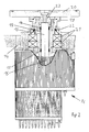
- the bearing plate 14 so train that it is provided in addition to the usual way recording the storage the rotor 15 of the drive motor 16, in addition, is capable of the connecting elements between the output shaft 13 of the drive motor 16 and the component to be driven, resulting in a significant reduction in the required installation space.
- the component to be driven is first a so-called drive element 19, which initially supports the functions of storage and sealing, and above addition, the mounting option for the outside of the drive motor located represents the component to be driven.
- the operative connection between the output shaft 13th the drive motor 16 and the drive element 19 are produced by a shaft tensioning sleeve 17, wherein the shaft tensioning sleeve 17 is deformed or prestressed by pressure pieces 18 is that the shaft tensioning sleeve 17, the output shaft 13 and the drive element 19 fixed without the generation of misalignment or angular offsets combines.
- connecting elements may as connecting elements but others, from the Prior art known elements used to connect the shaft and hub become. This may be e.g. around splined, polygonal, keyed, splined, splined, Screw, conical, annular spring clamping element or press-fit connections act.
- the component to be driven may be such as e.g. shown in FIG Bottle turntable 20 act, whereby the present invention in particular Dimensions suitable for this, the space problems shown above in rotary labeling machines to solve.
- the sealing elements 22 may be e.g. around O-rings, shaft seals or else also Simmerringe act.
- a clamping element 23 is provided, which supports the pressure pieces 18, e.g. through the transmission of the force effect applied by screws with appropriate forces.
- the invention provides, this depending on the planned Use of the drive motor specifically form.
- the drive of a component is planned, which is due to the accessibility of the location of the axis of rotation for direct mounting on the front side of drive element 19 and / or clamping element 23 is suitable, it is provided, drive element 19 and / or clamping element with corresponding fastening options, e.g. Tapped holes, equip.
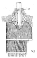
- FIG. 3 shows a further advantageous embodiment of the present invention, in which the torque of the drive motor 16 as possible to save space on the driven Component to be transferred, with this component, since the location of the axis of rotation not usable for attaching a fixture, not for a direct end face Mounting is suitable.
- the drive element of the component to be driven such that it the shape and dimensions of the clamping element 23rd corresponds and thus can take over its function and thus at the same time for attachment the component to be driven is used.
- the clamping element 23 by a appropriate structural design such. radially extending, in a receiving bore opening threaded holes, or also by attaching a Wellenendflansches suitable threaded holes with the drive element of the driven To perform connectable component.
Landscapes
- Engineering & Computer Science (AREA)
- Power Engineering (AREA)
- Connection Of Motors, Electrical Generators, Mechanical Devices, And The Like (AREA)
- Motor Or Generator Frames (AREA)
Abstract
Description
- Figur 1
- eine zum Stand der Technik gehörende Wellenverbindung und die
- Figur 2
- in einer stark vereinfachten Schnittdarstellung einen erfindungsgemäßen Antriebsmotor mit internen Verbindungselementen, wobei dieser Antriebsmotor für die stirnseitige Anordnung eines anzutreibenden Elementes vorgesehen ist, und die
- Figur 3
- in einer ebenfalls stark vereinfachten Schnittdarstellung einen erfindungsgemäßen Antriebsmotor mit internen Verbindungselementen, wobei die Antriebswelle des anzutreibenden Bauteils ein funktionaler Bestandteil der Verbindungselemente ist.
Claims (8)
- Elektrischer Antriebsmotor mit einem Rotor und einer, dass vom Rotor erzeugte Drehmoment abgebenden Abtriebswelle, insbesondere für den Antrieb von Flaschendrehtellern an Rundläufer-Etikettiermaschinen dadurch gekennzeichnet, dass die, die Verbindung zwischen Abtriebswelle (13) des Antriebsmotors (16) und dem anzutreibenden Bauteil herstellenden Verbindungselemente (17, 18, 19, 23) zumindest teilweise innerhalb des Antriebsmotors (16) angeordnet sind.
- Antriebsmotor nach Anspruch 1, dadurch gekennzeichnet, dass die Verbindungselemente (17, 18, 19, 23) zumindest teilweise innerhalb des Lagerschildes (14) angeordnet sind.
- Antriebsmotor nach Anspruch 1 oder 2, dadurch gekennzeichnet, dass die angeordnete Lagerung (21) sowohl zur Lagerung des Rotors (15), als auch zur Lagerung des anzutreibenden Bauteils dient.
- Antriebsmotor nach einem der vorhergehenden Ansprüche, dadurch gekennzeichnet, dass die Verbindungselemente (19, 23) derart ausgebildet sind, dass die Montage von anzutreibenden Bauteilen, bei denen der Ort der Drehachse zugänglich und somit für das Anbringen einer Befestigung verwendbar ist, direkt auf der Stirnseite der Verbindungselemente (19, 23) erfolgen kann.
- Antriebsmotor nach einem der vorhergehenden Ansprüche, dadurch gekennzeichnet, dass das Antriebselement des anzutreibenden Bauteils ein funktionaler Bestandteil der Verbindungselemente (19, 23) ist.
- Antriebsmotor nach einem der vorhergehenden Ansprüche, dadurch gekennzeichnet, dass es sich bei den Verbindungselementen (17, 18) um Elemente zur Verbindung von Wellen und Naben handelt.
- Antriebsmotor nach Anspruch 6, dadurch gekennzeichnet, dass es sich bei den Elementen zur Verbindung von Wellen und Naben um Ringfeder-Spannelemente handelt
- Antriebsmotor nach Anspruch 6, dadurch gekennzeichnet, dass es sich bei den Elementen zur Verbindung von Wellen und Naben um mindestes eine Wellenspannhülse (17) handelt.
Priority Applications (1)
| Application Number | Priority Date | Filing Date | Title |
|---|---|---|---|
| PL05010193T PL1596488T3 (pl) | 2004-05-14 | 2005-05-11 | Silnik napędowy ze zintegrowanymi elementami łączącymi wału |
Applications Claiming Priority (2)
| Application Number | Priority Date | Filing Date | Title |
|---|---|---|---|
| DE102004024136.8A DE102004024136B4 (de) | 2004-05-14 | 2004-05-14 | Antriebsmotor mit integrierten Wellenverbindungselementen |
| DE102004024136 | 2004-05-14 |
Publications (3)
| Publication Number | Publication Date |
|---|---|
| EP1596488A2 true EP1596488A2 (de) | 2005-11-16 |
| EP1596488A3 EP1596488A3 (de) | 2007-03-28 |
| EP1596488B1 EP1596488B1 (de) | 2014-01-01 |
Family
ID=34936373
Family Applications (1)
| Application Number | Title | Priority Date | Filing Date |
|---|---|---|---|
| EP05010193.0A Revoked EP1596488B1 (de) | 2004-05-14 | 2005-05-11 | Antriebsmotor mit integrierten Wellenverbindungselementen |
Country Status (3)
| Country | Link |
|---|---|
| EP (1) | EP1596488B1 (de) |
| DE (1) | DE102004024136B4 (de) |
| PL (1) | PL1596488T3 (de) |
Cited By (13)
| Publication number | Priority date | Publication date | Assignee | Title |
|---|---|---|---|---|
| EP1864911A1 (de) * | 2006-06-06 | 2007-12-12 | Sidel Holdings & Technology S.A. | Motor für eine Trägerplatte in einer Etikettiermaschine |
| WO2008145363A1 (de) * | 2007-05-31 | 2008-12-04 | Khs Ag | Maschine mit direktantrieb zur behandlung von behälter |
| EP2174874A1 (de) * | 2008-10-02 | 2010-04-14 | Schaeffler KG | Maschine zum rotativen Ausrichten eines Adapterelements gegenüber einem feststehenden Maschinenteil |
| WO2011110606A1 (en) | 2010-03-11 | 2011-09-15 | Sacmi Verona S.P.A. | Actuation motor, particularly for supporting pans or for winding spindles associated with a labeling machine |
| DE202015100659U1 (de) | 2015-02-11 | 2016-05-12 | Krones Ag | Behälterbehandlungsmaschine mit einem Drehtellerdirektantrieb |
| DE202016103046U1 (de) | 2016-06-08 | 2016-06-29 | Krones Ag | Ausdrückwerkzeug für einen Elektromotor |
| DE202015106913U1 (de) | 2015-12-17 | 2017-03-20 | Krones Ag | Behandlungsmaschine für Behälter |
| DE102016207583A1 (de) | 2016-05-03 | 2017-11-09 | Baumüller Holding GmbH & Co. KG | Behälterbehandlungsmaschine mit einem Drehtellerdirektantrieb |
| US20180010680A1 (en) * | 2016-07-08 | 2018-01-11 | Goodrich Actuation Systems Limited | Rotary sealing arrangement |
| DE102016124266A1 (de) | 2016-12-13 | 2018-06-14 | Krones Ag | Etikettiermaschine, Druckmaschine, Inspektionsmaschine und Verfahren zur Inbetriebnahme eines Bussystems in einer solchen Maschine |
| DE102015004085B4 (de) | 2015-03-31 | 2019-06-19 | Baumüller Directmotion Gmbh | Elektrischer Antriebsmotor, insbesondere Drehtellerantrieb |
| DE102015004084B4 (de) | 2015-03-31 | 2019-06-19 | Baumüller Directmotion Gmbh | Elektrischer Antriebsmotor, insbesondere Drehtellerantrieb |
| CN113460427A (zh) * | 2021-07-31 | 2021-10-01 | 秦皇岛中德实业有限公司 | 贴标机的伺服托瓶盘防水结构 |
Families Citing this family (1)
| Publication number | Priority date | Publication date | Assignee | Title |
|---|---|---|---|---|
| DE102015219937A1 (de) | 2015-10-14 | 2017-04-20 | Krones Aktiengesellschaft | Behandlungsmaschine für Behälter |
Citations (1)
| Publication number | Priority date | Publication date | Assignee | Title |
|---|---|---|---|---|
| DE10129172A1 (de) | 2001-06-16 | 2002-12-19 | Udo Schmalfus | Elektromotor als Antriebvorrichtung für eine anzutreibende Welle |
Family Cites Families (23)
| Publication number | Priority date | Publication date | Assignee | Title |
|---|---|---|---|---|
| GB674099A (en) | 1949-12-22 | 1952-06-18 | Wright Electric Motors Halifax | An improvement in or relating to means for coupling mechanisms to electric motors |
| DE1226987B (de) | 1961-05-23 | 1966-10-20 | Werner Winckelhaus | Ruehrwerksantrieb |
| CH600650A5 (de) | 1975-11-10 | 1978-06-30 | Magnetic Elektromotoren Ag | |
| DE2806080C2 (de) | 1978-02-14 | 1980-01-24 | Georg Obmann, Polytechnik Dieburg, 6110 Dieburg | Verfahren und Einrichtung zum Entfernen von Etiketten und/oder Halsfolien von Leerflaschen |
| CH657721A5 (de) | 1982-01-11 | 1986-09-15 | Papst Motoren Gmbh & Co Kg | Aussenlaeufer-direktantriebsmotor. |
| DE4302042C2 (de) | 1993-01-26 | 2000-06-08 | Hs Tech & Design | Elektromotor |
| US5450770A (en) | 1993-04-09 | 1995-09-19 | Miles Inc. | Integrated rotary drive apparatus |
| DE4440479C2 (de) | 1994-11-12 | 1997-08-21 | Temic Auto Electr Motors Gmbh | Elektromotorischer Antrieb für ein stirnseitig an einem Motorgehäuse anflanschbares Aggregat |
| US5917259A (en) | 1994-11-21 | 1999-06-29 | Stridsberg Innovation Ab | Coupling of an electric motor to a load |
| DE19607735A1 (de) | 1996-02-29 | 1997-09-04 | Siemens Ag | Verfahren zum Zusammenbau eines Kraftfahrzeug-Antriebes mit einem Elektromotor |
| DE29603843U1 (de) | 1996-03-01 | 1996-06-13 | Gsc Sperandio & Co | Integral-Elektronik für Servomotoren (Rubrik: Servomotoren) |
| DE19629346C2 (de) | 1996-07-20 | 1998-05-14 | Mannesmann Sachs Ag | Hybridantrieb |
| US6287074B1 (en) | 1997-03-31 | 2001-09-11 | Nate International | Mechanical seal for shafts and axles |
| ATE364487T1 (de) | 1998-06-16 | 2007-07-15 | Sumitomo Heavy Industries | Spritzgussmaschine |
| DE19910925A1 (de) | 1999-03-12 | 2000-09-14 | Blocher Motor Gmbh | Hebezeugantrieb |
| DE10034907A1 (de) | 2000-07-18 | 2002-01-31 | Khs Masch & Anlagenbau Ag | Maschine zum Behandeln von Flaschen, Dosen o. dgl. Behälter |
| US6472786B1 (en) | 2000-11-17 | 2002-10-29 | Ametek, Inc. | Bearing protection assembly for motors |
| DE10392007D2 (de) | 2002-04-29 | 2005-04-21 | Luk Lamellen & Kupplungsbau | BLDC-Motorbaugruppe |
| EP1511952B8 (de) | 2002-05-29 | 2008-03-26 | SEW-EURODRIVE GMBH & CO. | Standardantrieb, baureihe mit zwischenflansch |
| DE20304998U1 (de) | 2003-03-27 | 2003-08-21 | Minebea Co., Ltd., Miyota, Kitasaku | Elektromotor mit einem Motorgehäuse und einem Zugangsteil |
| DE10320599B4 (de) | 2003-05-08 | 2010-04-01 | Siemens Ag | Antriebsvorrichtung für Kunststoffextruder mit nach hinten herausnehmbarer Extruderschnecke |
| DE10338351A1 (de) | 2003-08-21 | 2005-03-17 | Faurecia Autositze Gmbh & Co.Kg | Elektromotor, insbesondere für Kraftfahrzeugsitze |
| DE10352014B4 (de) | 2003-11-07 | 2008-06-12 | Siemens Ag | Antrieb für einen Röntgenstrahler |
-
2004
- 2004-05-14 DE DE102004024136.8A patent/DE102004024136B4/de not_active Expired - Lifetime
-
2005
- 2005-05-11 EP EP05010193.0A patent/EP1596488B1/de not_active Revoked
- 2005-05-11 PL PL05010193T patent/PL1596488T3/pl unknown
Patent Citations (1)
| Publication number | Priority date | Publication date | Assignee | Title |
|---|---|---|---|---|
| DE10129172A1 (de) | 2001-06-16 | 2002-12-19 | Udo Schmalfus | Elektromotor als Antriebvorrichtung für eine anzutreibende Welle |
Cited By (21)
| Publication number | Priority date | Publication date | Assignee | Title |
|---|---|---|---|---|
| JP2007326648A (ja) * | 2006-06-06 | 2007-12-20 | Sidel Holdings & Technology Sa | ラベリング・マシンの容器保持プレートを駆動するためのモータ |
| EP1864911A1 (de) * | 2006-06-06 | 2007-12-12 | Sidel Holdings & Technology S.A. | Motor für eine Trägerplatte in einer Etikettiermaschine |
| US8907538B2 (en) | 2006-06-06 | 2014-12-09 | Sidel International Ag | Motor for driving a container-holder plate in a labelling machine |
| CN101087086B (zh) * | 2006-06-06 | 2013-05-08 | 西得乐控股和技术公司 | 用于在贴标机中驱动容器保持板的马达 |
| CN101678910B (zh) * | 2007-05-31 | 2013-12-18 | Khs有限责任公司 | 包括用于处理容器的直接驱动器的机器 |
| WO2008145363A1 (de) * | 2007-05-31 | 2008-12-04 | Khs Ag | Maschine mit direktantrieb zur behandlung von behälter |
| RU2429171C1 (ru) * | 2007-05-31 | 2011-09-20 | Кхс Аг | Машина с непосредственным приводом для обработки емкостей |
| EP2174874A1 (de) * | 2008-10-02 | 2010-04-14 | Schaeffler KG | Maschine zum rotativen Ausrichten eines Adapterelements gegenüber einem feststehenden Maschinenteil |
| WO2011110606A1 (en) | 2010-03-11 | 2011-09-15 | Sacmi Verona S.P.A. | Actuation motor, particularly for supporting pans or for winding spindles associated with a labeling machine |
| DE202015100659U1 (de) | 2015-02-11 | 2016-05-12 | Krones Ag | Behälterbehandlungsmaschine mit einem Drehtellerdirektantrieb |
| EP3056777A1 (de) | 2015-02-11 | 2016-08-17 | Krones AG | Behälterbehandlungsmaschine mit einem drehtellerdirektantrieb |
| DE102015004085B4 (de) | 2015-03-31 | 2019-06-19 | Baumüller Directmotion Gmbh | Elektrischer Antriebsmotor, insbesondere Drehtellerantrieb |
| DE102015004084B4 (de) | 2015-03-31 | 2019-06-19 | Baumüller Directmotion Gmbh | Elektrischer Antriebsmotor, insbesondere Drehtellerantrieb |
| DE202015106913U1 (de) | 2015-12-17 | 2017-03-20 | Krones Ag | Behandlungsmaschine für Behälter |
| DE102016207583A1 (de) | 2016-05-03 | 2017-11-09 | Baumüller Holding GmbH & Co. KG | Behälterbehandlungsmaschine mit einem Drehtellerdirektantrieb |
| DE202016103046U1 (de) | 2016-06-08 | 2016-06-29 | Krones Ag | Ausdrückwerkzeug für einen Elektromotor |
| US20180010680A1 (en) * | 2016-07-08 | 2018-01-11 | Goodrich Actuation Systems Limited | Rotary sealing arrangement |
| WO2018108331A1 (de) | 2016-12-13 | 2018-06-21 | Krones Ag | Etikettiermaschine, druckmaschine, inspektionsmaschine und verfahren zur inbetriebnahme eines bussystems in einer solchen maschine |
| DE102016124266A1 (de) | 2016-12-13 | 2018-06-14 | Krones Ag | Etikettiermaschine, Druckmaschine, Inspektionsmaschine und Verfahren zur Inbetriebnahme eines Bussystems in einer solchen Maschine |
| CN113460427A (zh) * | 2021-07-31 | 2021-10-01 | 秦皇岛中德实业有限公司 | 贴标机的伺服托瓶盘防水结构 |
| CN113460427B (zh) * | 2021-07-31 | 2025-03-14 | 秦皇岛中德实业有限公司 | 贴标机的伺服托瓶盘防水结构 |
Also Published As
| Publication number | Publication date |
|---|---|
| EP1596488A3 (de) | 2007-03-28 |
| EP1596488B1 (de) | 2014-01-01 |
| DE102004024136B4 (de) | 2023-08-10 |
| DE102004024136A1 (de) | 2005-12-01 |
| PL1596488T3 (pl) | 2014-06-30 |
Similar Documents
| Publication | Publication Date | Title |
|---|---|---|
| EP2652347B1 (de) | Elektrische maschine, insbesondere eines pumpenaggregates | |
| EP1596488B1 (de) | Antriebsmotor mit integrierten Wellenverbindungselementen | |
| EP2499361B1 (de) | Windturbine | |
| EP2902345B1 (de) | Trommelmotor für lärmempfindliche Umgebung | |
| DE102013004012B3 (de) | Elektromechanischer Dämpfer | |
| DE102008017262B4 (de) | Wälzlager-Drehverbindung mit integriertem Direktantrieb und mit integrierter Bremse | |
| DE102013208980A1 (de) | Retarderwelle | |
| DE102008018610A1 (de) | Stabilisatoranordnung | |
| AT410019B (de) | Motor-generator-anordnung | |
| DE102017123586A1 (de) | Elektrofahrzeug | |
| DE102012003386A1 (de) | Anordnung umfassend einen Verbrennungsmotor | |
| EP2686575A1 (de) | Bremse für windkraftanlagen | |
| DE102019118708A1 (de) | Druckversorgungseinrichtung mit einer Zahnradpumpe | |
| DE102015201146B4 (de) | Harmonisches Getriebe | |
| DE102015008716A1 (de) | Antriebsanordnung für eine Schwenkbrücke | |
| DE60003093T2 (de) | Kupplung für Pumpe und Motor | |
| DE102014214056A1 (de) | Verbindungsanordnung zwischen einem Wellenelement und einem Nabenelement | |
| DE102022112699A1 (de) | Antriebsvorrichtung zur linearen Kraftübertragung | |
| DE102021121909B3 (de) | Rotoreinheit einer elektrischen Axialflussmaschine und Elektrische Axialflussmaschine | |
| EP3260722B1 (de) | Bremse und antriebssystem mit bremse | |
| DE102006045490A1 (de) | Aktiver Kraftfahrzeugstabilisator mit eingebautem Aktuator | |
| EP4303466B1 (de) | Elektromechanischer linearaktuator mit hohlwellenmotor | |
| DE19903977A1 (de) | Anordnung zum Antrieb von Funktionselementen um mehrere unabhängige Achsen und Verfahren zu ihrer Herstellung | |
| WO2019206369A1 (de) | Hybridmodul, verfahren zur montage des hybridmoduls und antriebsanordnung | |
| DE102021115520B4 (de) | Drehmomentübertragungseinrichtung |
Legal Events
| Date | Code | Title | Description |
|---|---|---|---|
| PUAI | Public reference made under article 153(3) epc to a published international application that has entered the european phase |
Free format text: ORIGINAL CODE: 0009012 |
|
| AK | Designated contracting states |
Kind code of ref document: A2 Designated state(s): AT BE BG CH CY CZ DE DK EE ES FI FR GB GR HU IE IS IT LI LT LU MC NL PL PT RO SE SI SK TR |
|
| AX | Request for extension of the european patent |
Extension state: AL BA HR LV MK YU |
|
| RAP1 | Party data changed (applicant data changed or rights of an application transferred) |
Owner name: KHS AG |
|
| PUAL | Search report despatched |
Free format text: ORIGINAL CODE: 0009013 |
|
| AK | Designated contracting states |
Kind code of ref document: A3 Designated state(s): AT BE BG CH CY CZ DE DK EE ES FI FR GB GR HU IE IS IT LI LT LU MC NL PL PT RO SE SI SK TR |
|
| AX | Request for extension of the european patent |
Extension state: AL BA HR LV MK YU |
|
| AKX | Designation fees paid |
Designated state(s): AT BE BG CH CY CZ DE DK EE ES FI FR GB GR HU IE IS IT LI LT LU MC NL PL PT RO SE SI SK TR |
|
| 17P | Request for examination filed |
Effective date: 20070928 |
|
| RAP1 | Party data changed (applicant data changed or rights of an application transferred) |
Owner name: KHS GMBH |
|
| 17Q | First examination report despatched |
Effective date: 20121011 |
|
| GRAP | Despatch of communication of intention to grant a patent |
Free format text: ORIGINAL CODE: EPIDOSNIGR1 |
|
| INTG | Intention to grant announced |
Effective date: 20130806 |
|
| GRAS | Grant fee paid |
Free format text: ORIGINAL CODE: EPIDOSNIGR3 |
|
| GRAA | (expected) grant |
Free format text: ORIGINAL CODE: 0009210 |
|
| AK | Designated contracting states |
Kind code of ref document: B1 Designated state(s): AT BE BG CH CY CZ DE DK EE ES FI FR GB GR HU IE IS IT LI LT LU MC NL PL PT RO SE SI SK TR |
|
| REG | Reference to a national code |
Ref country code: GB Ref legal event code: FG4D Free format text: NOT ENGLISH |
|
| REG | Reference to a national code |
Ref country code: CH Ref legal event code: EP |
|
| REG | Reference to a national code |
Ref country code: IE Ref legal event code: FG4D Free format text: LANGUAGE OF EP DOCUMENT: GERMAN |
|
| REG | Reference to a national code |
Ref country code: DE Ref legal event code: R096 Ref document number: 502005014147 Country of ref document: DE Effective date: 20140213 |
|
| REG | Reference to a national code |
Ref country code: AT Ref legal event code: REF Ref document number: 647970 Country of ref document: AT Kind code of ref document: T Effective date: 20140215 |
|
| REG | Reference to a national code |
Ref country code: NL Ref legal event code: VDEP Effective date: 20140101 |
|
| REG | Reference to a national code |
Ref country code: LT Ref legal event code: MG4D |
|
| REG | Reference to a national code |
Ref country code: PL Ref legal event code: T3 |
|
| PG25 | Lapsed in a contracting state [announced via postgrant information from national office to epo] |
Ref country code: LT Free format text: LAPSE BECAUSE OF FAILURE TO SUBMIT A TRANSLATION OF THE DESCRIPTION OR TO PAY THE FEE WITHIN THE PRESCRIBED TIME-LIMIT Effective date: 20140101 Ref country code: IS Free format text: LAPSE BECAUSE OF FAILURE TO SUBMIT A TRANSLATION OF THE DESCRIPTION OR TO PAY THE FEE WITHIN THE PRESCRIBED TIME-LIMIT Effective date: 20140501 |
|
| PG25 | Lapsed in a contracting state [announced via postgrant information from national office to epo] |
Ref country code: NL Free format text: LAPSE BECAUSE OF FAILURE TO SUBMIT A TRANSLATION OF THE DESCRIPTION OR TO PAY THE FEE WITHIN THE PRESCRIBED TIME-LIMIT Effective date: 20140101 Ref country code: PT Free format text: LAPSE BECAUSE OF FAILURE TO SUBMIT A TRANSLATION OF THE DESCRIPTION OR TO PAY THE FEE WITHIN THE PRESCRIBED TIME-LIMIT Effective date: 20140502 Ref country code: SE Free format text: LAPSE BECAUSE OF FAILURE TO SUBMIT A TRANSLATION OF THE DESCRIPTION OR TO PAY THE FEE WITHIN THE PRESCRIBED TIME-LIMIT Effective date: 20140101 Ref country code: FI Free format text: LAPSE BECAUSE OF FAILURE TO SUBMIT A TRANSLATION OF THE DESCRIPTION OR TO PAY THE FEE WITHIN THE PRESCRIBED TIME-LIMIT Effective date: 20140101 Ref country code: CY Free format text: LAPSE BECAUSE OF FAILURE TO SUBMIT A TRANSLATION OF THE DESCRIPTION OR TO PAY THE FEE WITHIN THE PRESCRIBED TIME-LIMIT Effective date: 20140101 Ref country code: ES Free format text: LAPSE BECAUSE OF FAILURE TO SUBMIT A TRANSLATION OF THE DESCRIPTION OR TO PAY THE FEE WITHIN THE PRESCRIBED TIME-LIMIT Effective date: 20140101 |
|
| REG | Reference to a national code |
Ref country code: DE Ref legal event code: R026 Ref document number: 502005014147 Country of ref document: DE |
|
| PLBI | Opposition filed |
Free format text: ORIGINAL CODE: 0009260 |
|
| PG25 | Lapsed in a contracting state [announced via postgrant information from national office to epo] |
Ref country code: DK Free format text: LAPSE BECAUSE OF FAILURE TO SUBMIT A TRANSLATION OF THE DESCRIPTION OR TO PAY THE FEE WITHIN THE PRESCRIBED TIME-LIMIT Effective date: 20140101 Ref country code: CZ Free format text: LAPSE BECAUSE OF FAILURE TO SUBMIT A TRANSLATION OF THE DESCRIPTION OR TO PAY THE FEE WITHIN THE PRESCRIBED TIME-LIMIT Effective date: 20140101 Ref country code: EE Free format text: LAPSE BECAUSE OF FAILURE TO SUBMIT A TRANSLATION OF THE DESCRIPTION OR TO PAY THE FEE WITHIN THE PRESCRIBED TIME-LIMIT Effective date: 20140101 Ref country code: RO Free format text: LAPSE BECAUSE OF FAILURE TO SUBMIT A TRANSLATION OF THE DESCRIPTION OR TO PAY THE FEE WITHIN THE PRESCRIBED TIME-LIMIT Effective date: 20140101 |
|
| 26 | Opposition filed |
Opponent name: SEW-EURODRIVE GMBH & CO. KG Effective date: 20140930 Opponent name: KRONES AG Effective date: 20141001 Opponent name: DANFOSS A/S Effective date: 20140929 |
|
| PLAX | Notice of opposition and request to file observation + time limit sent |
Free format text: ORIGINAL CODE: EPIDOSNOBS2 |
|
| PG25 | Lapsed in a contracting state [announced via postgrant information from national office to epo] |
Ref country code: SK Free format text: LAPSE BECAUSE OF FAILURE TO SUBMIT A TRANSLATION OF THE DESCRIPTION OR TO PAY THE FEE WITHIN THE PRESCRIBED TIME-LIMIT Effective date: 20140101 |
|
| REG | Reference to a national code |
Ref country code: DE Ref legal event code: R026 Ref document number: 502005014147 Country of ref document: DE Effective date: 20140929 |
|
| PG25 | Lapsed in a contracting state [announced via postgrant information from national office to epo] |
Ref country code: LU Free format text: LAPSE BECAUSE OF FAILURE TO SUBMIT A TRANSLATION OF THE DESCRIPTION OR TO PAY THE FEE WITHIN THE PRESCRIBED TIME-LIMIT Effective date: 20140511 |
|
| REG | Reference to a national code |
Ref country code: CH Ref legal event code: PL |
|
| PG25 | Lapsed in a contracting state [announced via postgrant information from national office to epo] |
Ref country code: LI Free format text: LAPSE BECAUSE OF NON-PAYMENT OF DUE FEES Effective date: 20140531 Ref country code: MC Free format text: LAPSE BECAUSE OF FAILURE TO SUBMIT A TRANSLATION OF THE DESCRIPTION OR TO PAY THE FEE WITHIN THE PRESCRIBED TIME-LIMIT Effective date: 20140101 Ref country code: CH Free format text: LAPSE BECAUSE OF NON-PAYMENT OF DUE FEES Effective date: 20140531 |
|
| REG | Reference to a national code |
Ref country code: IE Ref legal event code: MM4A |
|
| PLBB | Reply of patent proprietor to notice(s) of opposition received |
Free format text: ORIGINAL CODE: EPIDOSNOBS3 |
|
| PG25 | Lapsed in a contracting state [announced via postgrant information from national office to epo] |
Ref country code: IE Free format text: LAPSE BECAUSE OF NON-PAYMENT OF DUE FEES Effective date: 20140511 |
|
| PG25 | Lapsed in a contracting state [announced via postgrant information from national office to epo] |
Ref country code: SI Free format text: LAPSE BECAUSE OF FAILURE TO SUBMIT A TRANSLATION OF THE DESCRIPTION OR TO PAY THE FEE WITHIN THE PRESCRIBED TIME-LIMIT Effective date: 20140101 |
|
| REG | Reference to a national code |
Ref country code: FR Ref legal event code: PLFP Year of fee payment: 12 |
|
| PG25 | Lapsed in a contracting state [announced via postgrant information from national office to epo] |
Ref country code: BG Free format text: LAPSE BECAUSE OF FAILURE TO SUBMIT A TRANSLATION OF THE DESCRIPTION OR TO PAY THE FEE WITHIN THE PRESCRIBED TIME-LIMIT Effective date: 20140101 |
|
| PG25 | Lapsed in a contracting state [announced via postgrant information from national office to epo] |
Ref country code: GR Free format text: LAPSE BECAUSE OF FAILURE TO SUBMIT A TRANSLATION OF THE DESCRIPTION OR TO PAY THE FEE WITHIN THE PRESCRIBED TIME-LIMIT Effective date: 20140402 |
|
| PG25 | Lapsed in a contracting state [announced via postgrant information from national office to epo] |
Ref country code: BE Free format text: LAPSE BECAUSE OF FAILURE TO SUBMIT A TRANSLATION OF THE DESCRIPTION OR TO PAY THE FEE WITHIN THE PRESCRIBED TIME-LIMIT Effective date: 20140531 Ref country code: TR Free format text: LAPSE BECAUSE OF FAILURE TO SUBMIT A TRANSLATION OF THE DESCRIPTION OR TO PAY THE FEE WITHIN THE PRESCRIBED TIME-LIMIT Effective date: 20140101 Ref country code: HU Free format text: LAPSE BECAUSE OF FAILURE TO SUBMIT A TRANSLATION OF THE DESCRIPTION OR TO PAY THE FEE WITHIN THE PRESCRIBED TIME-LIMIT; INVALID AB INITIO Effective date: 20050511 |
|
| RDAF | Communication despatched that patent is revoked |
Free format text: ORIGINAL CODE: EPIDOSNREV1 |
|
| STAA | Information on the status of an ep patent application or granted ep patent |
Free format text: STATUS: THE PATENT HAS BEEN GRANTED |
|
| APAH | Appeal reference modified |
Free format text: ORIGINAL CODE: EPIDOSCREFNO |
|
| APBM | Appeal reference recorded |
Free format text: ORIGINAL CODE: EPIDOSNREFNO |
|
| APBP | Date of receipt of notice of appeal recorded |
Free format text: ORIGINAL CODE: EPIDOSNNOA2O |
|
| REG | Reference to a national code |
Ref country code: FR Ref legal event code: PLFP Year of fee payment: 13 |
|
| APBQ | Date of receipt of statement of grounds of appeal recorded |
Free format text: ORIGINAL CODE: EPIDOSNNOA3O |
|
| REG | Reference to a national code |
Ref country code: FR Ref legal event code: PLFP Year of fee payment: 14 |
|
| PLAB | Opposition data, opponent's data or that of the opponent's representative modified |
Free format text: ORIGINAL CODE: 0009299OPPO |
|
| R26 | Opposition filed (corrected) |
Opponent name: DANFOSS A/S Effective date: 20140929 |
|
| RAP2 | Party data changed (patent owner data changed or rights of a patent transferred) |
Owner name: KHS GMBH |
|
| REG | Reference to a national code |
Ref country code: DE Ref legal event code: R103 Ref document number: 502005014147 Country of ref document: DE Ref country code: DE Ref legal event code: R064 Ref document number: 502005014147 Country of ref document: DE |
|
| APBU | Appeal procedure closed |
Free format text: ORIGINAL CODE: EPIDOSNNOA9O |
|
| PGFP | Annual fee paid to national office [announced via postgrant information from national office to epo] |
Ref country code: IT Payment date: 20210527 Year of fee payment: 17 Ref country code: FR Payment date: 20210520 Year of fee payment: 17 Ref country code: DE Payment date: 20210520 Year of fee payment: 17 |
|
| RDAG | Patent revoked |
Free format text: ORIGINAL CODE: 0009271 |
|
| STAA | Information on the status of an ep patent application or granted ep patent |
Free format text: STATUS: PATENT REVOKED |
|
| PGFP | Annual fee paid to national office [announced via postgrant information from national office to epo] |
Ref country code: GB Payment date: 20210520 Year of fee payment: 17 Ref country code: PL Payment date: 20210430 Year of fee payment: 17 Ref country code: AT Payment date: 20210520 Year of fee payment: 17 |
|
| REG | Reference to a national code |
Ref country code: FI Ref legal event code: MGE |
|
| 27W | Patent revoked |
Effective date: 20210616 |
|
| GBPR | Gb: patent revoked under art. 102 of the ep convention designating the uk as contracting state |
Effective date: 20210616 |
|
| REG | Reference to a national code |
Ref country code: AT Ref legal event code: MA03 Ref document number: 647970 Country of ref document: AT Kind code of ref document: T Effective date: 20210616 |