EP1596488A2 - Drive motor with integrated shaft connection element - Google Patents
Drive motor with integrated shaft connection element Download PDFInfo
- Publication number
- EP1596488A2 EP1596488A2 EP05010193A EP05010193A EP1596488A2 EP 1596488 A2 EP1596488 A2 EP 1596488A2 EP 05010193 A EP05010193 A EP 05010193A EP 05010193 A EP05010193 A EP 05010193A EP 1596488 A2 EP1596488 A2 EP 1596488A2
- Authority
- EP
- European Patent Office
- Prior art keywords
- drive motor
- elements
- driven
- motor according
- component
- Prior art date
- Legal status (The legal status is an assumption and is not a legal conclusion. Google has not performed a legal analysis and makes no representation as to the accuracy of the status listed.)
- Granted
Links
Images

Classifications
-
- B—PERFORMING OPERATIONS; TRANSPORTING
- B65—CONVEYING; PACKING; STORING; HANDLING THIN OR FILAMENTARY MATERIAL
- B65C—LABELLING OR TAGGING MACHINES, APPARATUS, OR PROCESSES
- B65C9/00—Details of labelling machines or apparatus
- B65C9/02—Devices for moving articles, e.g. containers, past labelling station
- B65C9/04—Devices for moving articles, e.g. containers, past labelling station having means for rotating the articles
-
- H—ELECTRICITY
- H02—GENERATION; CONVERSION OR DISTRIBUTION OF ELECTRIC POWER
- H02K—DYNAMO-ELECTRIC MACHINES
- H02K7/00—Arrangements for handling mechanical energy structurally associated with dynamo-electric machines, e.g. structural association with mechanical driving motors or auxiliary dynamo-electric machines
- H02K7/003—Couplings; Details of shafts
Definitions
- the present invention relates to a drive motor according to the preamble of the claim 1.
- Advantageous developments are specified in the subclaims.
- these motors are DC, AC, three-phase motors can act.
- these motors may be servo, synchronous (in the sense of a given movement or motion command following) or act by stepper motors.
- the object and purpose of the present invention is to overcome the disadvantages described above avoid.
- the invention provides that the elements for connecting the two Waves in the interior of the drive motor, in a particularly advantageous embodiment be moved into the interior of the bearing plate of the drive motor.
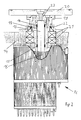
- the bearing plate 14 so train that it is provided in addition to the usual way recording the storage the rotor 15 of the drive motor 16, in addition, is capable of the connecting elements between the output shaft 13 of the drive motor 16 and the component to be driven, resulting in a significant reduction in the required installation space.
- the component to be driven is first a so-called drive element 19, which initially supports the functions of storage and sealing, and above addition, the mounting option for the outside of the drive motor located represents the component to be driven.
- the operative connection between the output shaft 13th the drive motor 16 and the drive element 19 are produced by a shaft tensioning sleeve 17, wherein the shaft tensioning sleeve 17 is deformed or prestressed by pressure pieces 18 is that the shaft tensioning sleeve 17, the output shaft 13 and the drive element 19 fixed without the generation of misalignment or angular offsets combines.
- connecting elements may as connecting elements but others, from the Prior art known elements used to connect the shaft and hub become. This may be e.g. around splined, polygonal, keyed, splined, splined, Screw, conical, annular spring clamping element or press-fit connections act.
- the component to be driven may be such as e.g. shown in FIG Bottle turntable 20 act, whereby the present invention in particular Dimensions suitable for this, the space problems shown above in rotary labeling machines to solve.
- the sealing elements 22 may be e.g. around O-rings, shaft seals or else also Simmerringe act.
- a clamping element 23 is provided, which supports the pressure pieces 18, e.g. through the transmission of the force effect applied by screws with appropriate forces.
- the invention provides, this depending on the planned Use of the drive motor specifically form.
- the drive of a component is planned, which is due to the accessibility of the location of the axis of rotation for direct mounting on the front side of drive element 19 and / or clamping element 23 is suitable, it is provided, drive element 19 and / or clamping element with corresponding fastening options, e.g. Tapped holes, equip.
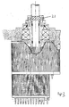
- FIG. 3 shows a further advantageous embodiment of the present invention, in which the torque of the drive motor 16 as possible to save space on the driven Component to be transferred, with this component, since the location of the axis of rotation not usable for attaching a fixture, not for a direct end face Mounting is suitable.
- the drive element of the component to be driven such that it the shape and dimensions of the clamping element 23rd corresponds and thus can take over its function and thus at the same time for attachment the component to be driven is used.
- the clamping element 23 by a appropriate structural design such. radially extending, in a receiving bore opening threaded holes, or also by attaching a Wellenendflansches suitable threaded holes with the drive element of the driven To perform connectable component.
Landscapes
- Engineering & Computer Science (AREA)
- Power Engineering (AREA)
- Connection Of Motors, Electrical Generators, Mechanical Devices, And The Like (AREA)
- Motor Or Generator Frames (AREA)
Abstract
Description
Die vorliegende Erfindung betrifft einen Antriebsmotor gemäß dem Oberbegriff des Anspruches 1. Vorteilhaft Weiterbildungen sind in den Unteransprüchen angegeben.The present invention relates to a drive motor according to the preamble of the claim 1. Advantageous developments are specified in the subclaims.
In der Technik ist es seit langem üblich, für bestimmte Antriebsaufgaben Elektromotoren einzusetzen, wobei es sich bei diesen Motoren um Gleichstrom-, Wechselstrom-, Drehstrommotoren handeln kann. Ebenfalls kann es sich bei diesen Motoren um Servo-, Synchron- (im Sinne von einer vorgegebenen Bewegung oder einem vorgegebenen Bewegungsbefehl folgend) oder auch um Schrittmotoren handeln.In the art, it has long been common for certain drive tasks electric motors be used, these motors are DC, AC, three-phase motors can act. Likewise, these motors may be servo, synchronous (in the sense of a given movement or motion command following) or act by stepper motors.
Ebenfalls ist es üblich, den für eine Antriebsaufgabe eingesetzten Elektromotor mit dem anzutreibenden Element zu verbinden. Dazu wurden im Laufe der Zeit zahlreiche Lösungsvorschläge erarbeitet und vorgestellt. So wurden z.B. zahlreiche Vorrichtungen vorgestellt, bei denen Abtriebswelle und anzutreibende Welle durch starre oder flexible Kupplungen verbunden werden, bei denen je ein Befestigungselement auf einer der beiden Wellen befestigt wird.It is also common for the electric motor used for a drive task with the To connect to be driven element. In the course of time, numerous solutions were proposed developed and presented. For example, numerous devices presented, where the output shaft and driven shaft by rigid or flexible couplings be connected, in which each has a fastener on one of the two Waves is attached.
Ebenfalls wurden Kupplungen vorgestellt, bei denen ein rohrähnliches oder aber auch halbschalenförmiges Element mit beiden Wellen verbunden wird und diese somit miteinander verbindet.Also couplings were presented in which a tube-like or else half-shell-shaped element is connected to both shafts and thus these together combines.
Allen der Anmelderin bekannt gewordenen Elementen zur Verbindung von einer Abtriebswelle und einer anzutreibenden Welle, wobei die Drehachsen beider Wellen im Wesentlichen auf einer Linie liegen, ist gemeinsam, dass der Platzbedarf dieser Elemente groß ist, da die beiden zu verbindenden Wellenenden zumindest so weit in den freien Raum ragen müssen, dass diese Wellenenden in der Lage sind, das oder die auf ihnen zu befestigende(n) Verbindungselement(e) sicher aufnehmen zu können.All of the Applicant become known elements for connection of an output shaft and a driven shaft, wherein the axes of rotation of both shafts substantially lie in a line, have in common that the space requirements of these elements is large, since the two shaft ends to be joined protrude at least as far into free space that these shaft ends are capable of carrying the one or more To receive fastener (s) safely.
Dieses ist insbesondere dann von großem Nachteil, wenn der zur Verfügung stehende Bauraum begrenzt ist.This is particularly disadvantageous if the available Space is limited.
Dieses ist z.B. auch bei bekannten Rundläufer-Etikettiermaschinen, bei denen die dort
vorgesehenen Flaschendrehteller 20 jeweils durch einen Elektromotor angetrieben bzw.
angesteuert werden, der Fall.This is e.g. even with known rotary labeling machines, where the there
provided
Aufgabe und Ziel der vorliegenden Erfindung ist es, die oben dargestellten Nachteile zu vermeiden. Dazu sieht die Erfindung vor, dass die Elemente zur Verbindung der beiden Wellen in das Innere des Antriebsmotors, in einer besonders vorteilhaften Ausgestaltung in das Innere des Lagerschildes des Antriebsmotors verlegt werden.The object and purpose of the present invention is to overcome the disadvantages described above avoid. For this purpose, the invention provides that the elements for connecting the two Waves in the interior of the drive motor, in a particularly advantageous embodiment be moved into the interior of the bearing plate of the drive motor.
Im Nachfolgenden wird die vorliegende Erfindung anhand eines Ausführungsbeispieles näher erläutert.In the following, the present invention will be described with reference to an embodiment explained in more detail.
Im Einzelnen zeigt die
- Figur 1
- eine zum Stand der Technik gehörende Wellenverbindung und die
- Figur 2
- in einer stark vereinfachten Schnittdarstellung einen erfindungsgemäßen Antriebsmotor mit internen Verbindungselementen, wobei dieser Antriebsmotor für die stirnseitige Anordnung eines anzutreibenden Elementes vorgesehen ist, und die
- Figur 3
- in einer ebenfalls stark vereinfachten Schnittdarstellung einen erfindungsgemäßen Antriebsmotor mit internen Verbindungselementen, wobei die Antriebswelle des anzutreibenden Bauteils ein funktionaler Bestandteil der Verbindungselemente ist.
- FIG. 1
- a belonging to the prior art wave connection and the
- FIG. 2
- in a highly simplified sectional view of a drive motor according to the invention with internal connecting elements, said drive motor is provided for the frontal arrangement of a driven element, and the
- FIG. 3
- in a likewise greatly simplified sectional view of a drive motor according to the invention with internal connecting elements, wherein the drive shaft of the component to be driven is a functional part of the connecting elements.
Weiterbildungen, Vorteile und Anwendungsmöglichkeiten der Erfindung ergeben sich aus der nachfolgenden Beschreibung von Ausführungsbeispielen und der Zeichnung. Dabei bilden alle beschriebenen und/oder bildlich dargestellten Merkmale für sich oder in beliebiger Kombination den Gegenstand der Erfindung, unabhängig von ihrer Zusammenfassung in den Ansprüchen oder deren Rückbeziehung. Gleichzeitig wird der Inhalt der Ansprüche zu einem Bestandteil der Beschreibung gemacht.Further developments, advantages and applications of the invention will become apparent the following description of exemplary embodiments and the drawing. there form all described and / or illustrated features alone or in any Combination of the subject matter of the invention, regardless of their summary in the claims or their dependency. At the same time, the content of the claims made part of the description.
Wie in der Figur 2 dargestellt, sieht die vorliegende Erfindung vor, das Lagerschild 14 derart
auszubilden, dass es neben der üblicher Weise vorgesehenen Aufnahme der Lagerung
des Rotors 15 des Antriebsmotors 16, zusätzlich in der Lage ist, die Verbindungselemente
zwischen Abtriebswelle 13 des Antriebsmotors 16 und dem anzutreibenden Bauteil aufzunehmen,
wodurch sich eine deutliche Reduzierung des erforderlichen Bauraumes ergibt.As shown in Figure 2, the present invention, the bearing plate 14 so
train that it is provided in addition to the usual way recording the storage
the
Erfindungsgemäß ist das anzutreibende Bauteil zunächst ein so genannten Antriebselement
19, welches zunächst die Funktionen Lagerung und Abdichtung unterstützt, und darüber
hinaus die Befestigungsmöglichkeit für das außerhalb des Antriebsmotors befindliche
anzutreibende Bauteil darstellt.According to the invention, the component to be driven is first a so-called
Im dargestellten Ausführungsbeispiel wird die Wirkverbindung zwischen Abtriebswelle 13
des Antriebsmotors 16 und dem Antriebselement 19 durch eine Wellenspannhülse 17 hergestellt,
wobei die Wellenspannhülse 17 durch Druckstücke 18 derart verformt bzw. vorgespannt
wird, dass die Wellenspannhülse 17 die Abtriebswelle 13 und das Antriebselement
19 ohne die Erzeugung von Fluchtungsfehlern oder Winkelversätzen fest miteinander
verbindet.In the illustrated embodiment, the operative connection between the output shaft 13th
the
In weiteren Ausbildungen können als Verbindungselemente aber auch andere, aus dem Stand der Technik bekannte Elemente zur Verbindung von Welle und Nabe verwendet werden. Dabei kann es sich z.B. um Vielkeil-, Polygon-, Passfeder- , Keilwellen-, Zahnwellen-, Schraub- , Kegel-, Ringfeder-Spannelement- oder Presssitzverbindungen handeln.In other embodiments may as connecting elements but others, from the Prior art known elements used to connect the shaft and hub become. This may be e.g. around splined, polygonal, keyed, splined, splined, Screw, conical, annular spring clamping element or press-fit connections act.
Auch die Verwendung, weiterer, an dieser Stelle nicht ausdrücklich erwähnter Verbindungselemente führt nicht dazu, dass der Schutzbereich der vorliegenden Erfindung verlassen wird.The use, further, not explicitly mentioned at this point fasteners does not leave the scope of the present invention becomes.
Durch die Verbindung von Abtriebswelle 13 und Antriebselement 19 wird das vom Rotor
15 des Antriebsmotors 16 erzeugte Drehmoment sicher und schlupffrei auf
das Antriebselement 19 und auf das anzutreibende Bauteil übertragen.By the connection of the
Wie die in Figur 2 dargestellte Konstruktion erkennen lässt, dient die in das Lagerschild 14
integrierte Lagerung 21 sowohl zur Lagerung des Rotors 15 des Antriebsmotors 16, als
auch zur Lagerung des Antriebselementes 19, wobei Rotor 15 und Antriebselement 19
durch die Wellenspannhülse 17 auf besonders vorteilhafte Weise miteinander verbunden
sind. Ebenfalls übernimmt die Lagerung 21 - so weit erforderlich - auch die Lagerung des
anzutreibenden Bauteils.As can be seen in the construction shown in FIG. 2, it is used in the end shield 14
integrated storage 21 both for storage of the
Durch diese Vorgehensweise ergeben sich weitere konstruktive und kostenmäßige Vorteile.By doing so, there are more constructive and cost advantages.
Bei dem anzutreibenden Bauteil kann es sich, wie z.B. in der Figur 2 gezeigt, um einen
Flaschendrehteller 20 handeln, wodurch sich die vorliegende Erfindung in besonderem
Maße dazu eignet, die oben dargestellten Raumprobleme bei Rundläufer-Etikettiermaschinen
zu lösen.The component to be driven may be such as e.g. shown in
Ebenfalls dienen das Lagerschild 14 und das Antriebselement 19 auch zur Aufnahme von
Dichtelementen 22, welche den Antriebsmotor vor dem Eindringen von Schmutz und/oder
Feuchtigkeit schützen sollen.Also serve the bearing plate 14 and the
Bei den Dichtelementen 22 kann es sich z.B. um O-Ringe, Wellendichtringe oder aber auch Simmerringe handeln. Bei der Lagerung 21 kann es sich z.B. um Kugellager, Pendelrollenlager, Zylinderrollenlager oder andere geeignete Lagerbauformen handeln. The sealing elements 22 may be e.g. around O-rings, shaft seals or else also Simmerringe act. In storage 21, e.g. around ball bearings, spherical roller bearings, Cylindrical roller bearings or other suitable bearing types act.
Um die Druckstücke 18 mit der, zum hinreichenden Verformen bzw. Vorspannen der Wellenspannhülse
17 erforderlichen Axialkraft beaufschlagen zu können, ist ein Spannelement
23 vorgesehen, welches die Druckstücke 18 z.B. durch die Weiterleitung der Kraftwirkung
von Gewindeschrauben mit entsprechenden Kräften beaufschlagt.To the plungers 18 with, for sufficient deformation or biasing the shaft tension sleeve
To apply 17 required axial force is a
Für die Gestaltung des Spannelementes 23 sieht die Erfindung vor, dieses je nach geplanter
Verwendung des Antriebsmotors spezifisch auszubilden.For the design of the
Ist z.B., so wie in der Figur 2 dargestellt, der Antrieb eines Bauteils geplant, welches sich
aufgrund der Zugänglichkeit des Ortes der Drehachse zur direkten Montage auf der Stirnseite
von Antriebselement 19 und/oder Spannelement 23 eignet, so ist vorgesehen, Antriebselement
19 und/oder Spannelement mit entsprechenden Befestigungsmöglichkeiten,
z.B. Gewindebohrungen, auszustatten.For example, as shown in Figure 2, the drive of a component is planned, which is
due to the accessibility of the location of the axis of rotation for direct mounting on the front side
of
Die Figur 3 zeigt eine weitere vorteilhafte Ausbildung der vorliegenden Erfindung, bei welcher
das Drehmoment des Antriebsmotors 16 möglichst platzsparend auf das anzutreibend
Bauteil übertragen werden soll, wobei sich dieses Bauteil, da der Ort der Drehachse
nicht für die Anbringung einer Befestigung verwendbar ist, nicht für eine direkte stirnseitige
Montage eignet.FIG. 3 shows a further advantageous embodiment of the present invention, in which
the torque of the
Für einen solchen Fall ist vorgesehen, das Antriebselement des anzutreibenden Bauteils derart auszubilden, dass es der Gestalt und den Abmessungen des Spannelementes 23 entspricht und somit dessen Funktion übernehmen kann und somit gleichzeitig zur Befestigung des anzutreibenden Bauteiles dient.For such a case is provided, the drive element of the component to be driven such that it the shape and dimensions of the clamping element 23rd corresponds and thus can take over its function and thus at the same time for attachment the component to be driven is used.
Weiterhin ist in einer weiteren Ausbildung vorgesehen, das Spannelement 23 durch eine
entsprechende konstruktive Gestaltung wie z.B. radial verlaufende, in einer Aufnahmebohrung
mündende Gewindebohrungen, oder aber auch durch zur Befestigung eines Wellenendflansches
geeignete Gewindebohrungen mit dem Antriebselement des anzutreibenden
Bauteils verbindbar auszuführen.Furthermore, it is provided in a further embodiment, the
Auch die Anwendung abweichender, aber wirkungsgleicher konstruktiver Ausgestaltungen führt nicht dazu, dass der Schutzbereich der vorliegenden Erfindung verlassen wird.Also, the use of deviating, but effect same constructive configurations does not cause the scope of protection of the present invention to be abandoned.
Claims (8)
Priority Applications (1)
| Application Number | Priority Date | Filing Date | Title |
|---|---|---|---|
| PL05010193T PL1596488T3 (en) | 2004-05-14 | 2005-05-11 | Drive motor with integrated shaft connection element |
Applications Claiming Priority (2)
| Application Number | Priority Date | Filing Date | Title |
|---|---|---|---|
| DE102004024136.8A DE102004024136B4 (en) | 2004-05-14 | 2004-05-14 | Drive motor with integrated shaft connection elements |
| DE102004024136 | 2004-05-14 |
Publications (3)
| Publication Number | Publication Date |
|---|---|
| EP1596488A2 true EP1596488A2 (en) | 2005-11-16 |
| EP1596488A3 EP1596488A3 (en) | 2007-03-28 |
| EP1596488B1 EP1596488B1 (en) | 2014-01-01 |
Family
ID=34936373
Family Applications (1)
| Application Number | Title | Priority Date | Filing Date |
|---|---|---|---|
| EP05010193.0A Revoked EP1596488B1 (en) | 2004-05-14 | 2005-05-11 | Drive motor with integrated shaft connection element |
Country Status (3)
| Country | Link |
|---|---|
| EP (1) | EP1596488B1 (en) |
| DE (1) | DE102004024136B4 (en) |
| PL (1) | PL1596488T3 (en) |
Cited By (12)
| Publication number | Priority date | Publication date | Assignee | Title |
|---|---|---|---|---|
| EP1864911A1 (en) * | 2006-06-06 | 2007-12-12 | Sidel Holdings & Technology S.A. | Motor for a support plate in a labelling machine |
| WO2008145363A1 (en) * | 2007-05-31 | 2008-12-04 | Khs Ag | Machine having a direct drive for the treatment of containers |
| EP2174874A1 (en) * | 2008-10-02 | 2010-04-14 | Schaeffler KG | Machine for rotating alignment of an adapter element relative to a fixed machine part |
| WO2011110606A1 (en) | 2010-03-11 | 2011-09-15 | Sacmi Verona S.P.A. | Actuation motor, particularly for supporting pans or for winding spindles associated with a labeling machine |
| DE202015100659U1 (en) | 2015-02-11 | 2016-05-12 | Krones Ag | Container handling machine with a turntable direct drive |
| DE202016103046U1 (en) | 2016-06-08 | 2016-06-29 | Krones Ag | Extraction tool for an electric motor |
| DE202015106913U1 (en) | 2015-12-17 | 2017-03-20 | Krones Ag | Treatment machine for containers |
| DE102016207583A1 (en) | 2016-05-03 | 2017-11-09 | Baumüller Holding GmbH & Co. KG | Container handling machine with a turntable direct drive |
| US20180010680A1 (en) * | 2016-07-08 | 2018-01-11 | Goodrich Actuation Systems Limited | Rotary sealing arrangement |
| DE102016124266A1 (en) | 2016-12-13 | 2018-06-14 | Krones Ag | Labeling machine, printing machine, inspection machine and method for commissioning a bus system in such a machine |
| DE102015004084B4 (en) | 2015-03-31 | 2019-06-19 | Baumüller Directmotion Gmbh | Electric drive motor, in particular turntable drive |
| DE102015004085B4 (en) | 2015-03-31 | 2019-06-19 | Baumüller Directmotion Gmbh | Electric drive motor, in particular turntable drive |
Families Citing this family (1)
| Publication number | Priority date | Publication date | Assignee | Title |
|---|---|---|---|---|
| DE102015219937A1 (en) | 2015-10-14 | 2017-04-20 | Krones Aktiengesellschaft | Treatment machine for containers |
Citations (1)
| Publication number | Priority date | Publication date | Assignee | Title |
|---|---|---|---|---|
| DE10129172A1 (en) | 2001-06-16 | 2002-12-19 | Udo Schmalfus | Electric motor as shaft drive arrangement, has through bore machined into housing centrally to motor rotation axis; shaft is inserted in hollow shaft mounted in bore and joined to rotor |
Family Cites Families (24)
| Publication number | Priority date | Publication date | Assignee | Title |
|---|---|---|---|---|
| GB674099A (en) | 1949-12-22 | 1952-06-18 | Wright Electric Motors Halifax | An improvement in or relating to means for coupling mechanisms to electric motors |
| DE897129C (en) | 1951-06-14 | 1953-11-19 | Singer Mfg Co | Electric motor with built-in clutch and brake |
| DE1226987B (en) | 1961-05-23 | 1966-10-20 | Werner Winckelhaus | Agitator drive |
| CH600650A5 (en) | 1975-11-10 | 1978-06-30 | Magnetic Elektromotoren Ag | |
| DE2806080C2 (en) | 1978-02-14 | 1980-01-24 | Georg Obmann, Polytechnik Dieburg, 6110 Dieburg | Method and device for removing labels and / or neck films from empty bottles |
| CH657721A5 (en) | 1982-01-11 | 1986-09-15 | Papst Motoren Gmbh & Co Kg | OUTDOOR RUNNER DIRECT DRIVE MOTOR. |
| DE4302042C2 (en) | 1993-01-26 | 2000-06-08 | Hs Tech & Design | Electric motor |
| US5450770A (en) | 1993-04-09 | 1995-09-19 | Miles Inc. | Integrated rotary drive apparatus |
| DE4440479C2 (en) | 1994-11-12 | 1997-08-21 | Temic Auto Electr Motors Gmbh | Electric motor drive for an aggregate that can be flanged to the front of a motor housing |
| US5917259A (en) | 1994-11-21 | 1999-06-29 | Stridsberg Innovation Ab | Coupling of an electric motor to a load |
| DE19607735A1 (en) | 1996-02-29 | 1997-09-04 | Siemens Ag | Assembling vehicle drive with electric motor |
| DE29603843U1 (en) | 1996-03-01 | 1996-06-13 | Gsc Sperandio & Co | Integral electronics for servo motors (Category: Servo motors) |
| DE19629346C2 (en) | 1996-07-20 | 1998-05-14 | Mannesmann Sachs Ag | Hybrid drive |
| US6287074B1 (en) | 1997-03-31 | 2001-09-11 | Nate International | Mechanical seal for shafts and axles |
| KR100376614B1 (en) | 1998-06-16 | 2003-03-19 | 스미도모쥬기가이고교 가부시키가이샤 | Injection molding machine |
| DE19910925A1 (en) | 1999-03-12 | 2000-09-14 | Blocher Motor Gmbh | Compact gearless drive for lifts carrying individuals or goods, turns electric motor inside-out, mounting stator on bearing support and rotor inside pulley, resulting in compact, maintainable unit |
| DE10034907A1 (en) | 2000-07-18 | 2002-01-31 | Khs Masch & Anlagenbau Ag | Machine for handling bottles, cans or similar containers |
| US6472786B1 (en) | 2000-11-17 | 2002-10-29 | Ametek, Inc. | Bearing protection assembly for motors |
| DE10318972A1 (en) | 2002-04-29 | 2003-11-06 | Luk Lamellen & Kupplungsbau | Brushless D.C. motor unit, e.g. for electronically controlled clutch in vehicle, has second part axially held by first part (metal motor shaft) and/or axially fixed to first part by deforming first part with tool |
| ATE381687T1 (en) | 2002-05-29 | 2008-01-15 | Sew Eurodrive Gmbh & Co | STANDARD DRIVE, SERIES WITH INTERMEDIATE FLANGE |
| DE20304998U1 (en) | 2003-03-27 | 2003-08-21 | Minebea Co Ltd | Electric motor with a motor housing and an access part |
| DE10320599B4 (en) | 2003-05-08 | 2010-04-01 | Siemens Ag | Drive device for plastic extruder with backward removable extruder screw |
| DE10338351A1 (en) | 2003-08-21 | 2005-03-17 | Faurecia Autositze Gmbh & Co.Kg | Electric motor designed for vehicle seats, has insert locked against rotation in recess, with plug-in opening interlocking with motor torque shaft |
| DE10352014B4 (en) | 2003-11-07 | 2008-06-12 | Siemens Ag | Drive for an X-ray source |
-
2004
- 2004-05-14 DE DE102004024136.8A patent/DE102004024136B4/en active Active
-
2005
- 2005-05-11 EP EP05010193.0A patent/EP1596488B1/en not_active Revoked
- 2005-05-11 PL PL05010193T patent/PL1596488T3/en unknown
Patent Citations (1)
| Publication number | Priority date | Publication date | Assignee | Title |
|---|---|---|---|---|
| DE10129172A1 (en) | 2001-06-16 | 2002-12-19 | Udo Schmalfus | Electric motor as shaft drive arrangement, has through bore machined into housing centrally to motor rotation axis; shaft is inserted in hollow shaft mounted in bore and joined to rotor |
Cited By (18)
| Publication number | Priority date | Publication date | Assignee | Title |
|---|---|---|---|---|
| EP1864911A1 (en) * | 2006-06-06 | 2007-12-12 | Sidel Holdings & Technology S.A. | Motor for a support plate in a labelling machine |
| JP2007326648A (en) * | 2006-06-06 | 2007-12-20 | Sidel Holdings & Technology Sa | Motor to drive container-holding plate of labelling machine |
| CN101087086B (en) * | 2006-06-06 | 2013-05-08 | 西得乐控股和技术公司 | Motor for driving a container-holder plate in a labelling machine |
| US8907538B2 (en) | 2006-06-06 | 2014-12-09 | Sidel International Ag | Motor for driving a container-holder plate in a labelling machine |
| WO2008145363A1 (en) * | 2007-05-31 | 2008-12-04 | Khs Ag | Machine having a direct drive for the treatment of containers |
| CN101678910B (en) * | 2007-05-31 | 2013-12-18 | Khs有限责任公司 | Machine having direct drive for treatment of containers |
| EP2174874A1 (en) * | 2008-10-02 | 2010-04-14 | Schaeffler KG | Machine for rotating alignment of an adapter element relative to a fixed machine part |
| WO2011110606A1 (en) | 2010-03-11 | 2011-09-15 | Sacmi Verona S.P.A. | Actuation motor, particularly for supporting pans or for winding spindles associated with a labeling machine |
| DE202015100659U1 (en) | 2015-02-11 | 2016-05-12 | Krones Ag | Container handling machine with a turntable direct drive |
| EP3056777A1 (en) | 2015-02-11 | 2016-08-17 | Krones AG | Machine for treating containers comprising a rotating disc direct drive |
| DE102015004084B4 (en) | 2015-03-31 | 2019-06-19 | Baumüller Directmotion Gmbh | Electric drive motor, in particular turntable drive |
| DE102015004085B4 (en) | 2015-03-31 | 2019-06-19 | Baumüller Directmotion Gmbh | Electric drive motor, in particular turntable drive |
| DE202015106913U1 (en) | 2015-12-17 | 2017-03-20 | Krones Ag | Treatment machine for containers |
| DE102016207583A1 (en) | 2016-05-03 | 2017-11-09 | Baumüller Holding GmbH & Co. KG | Container handling machine with a turntable direct drive |
| DE202016103046U1 (en) | 2016-06-08 | 2016-06-29 | Krones Ag | Extraction tool for an electric motor |
| US20180010680A1 (en) * | 2016-07-08 | 2018-01-11 | Goodrich Actuation Systems Limited | Rotary sealing arrangement |
| DE102016124266A1 (en) | 2016-12-13 | 2018-06-14 | Krones Ag | Labeling machine, printing machine, inspection machine and method for commissioning a bus system in such a machine |
| WO2018108331A1 (en) | 2016-12-13 | 2018-06-21 | Krones Ag | Labeling machine, printing machine, inspection machine, and method for starting up a bus system in such a machine |
Also Published As
| Publication number | Publication date |
|---|---|
| DE102004024136A1 (en) | 2005-12-01 |
| EP1596488A3 (en) | 2007-03-28 |
| EP1596488B1 (en) | 2014-01-01 |
| DE102004024136B4 (en) | 2023-08-10 |
| PL1596488T3 (en) | 2014-06-30 |
Similar Documents
| Publication | Publication Date | Title |
|---|---|---|
| EP1596488B1 (en) | Drive motor with integrated shaft connection element | |
| EP2652347A1 (en) | Electric machine, in particular of a pump unit | |
| DE102013004012B3 (en) | Electromechanical damper | |
| EP2902345B1 (en) | Drum motor for noise-sensitive environment | |
| DE102008017262B4 (en) | Rolling bearing slewing connection with integrated direct drive and with integrated brake | |
| DE102013208980A1 (en) | retarder | |
| DE102008018610A1 (en) | Stabilizer arrangement for balancing of vehicle body movement, has coupling elements supported swivelably on both ends, where coupling elements stay in effective connection with rotary shaft and electrically driveable drive element | |
| EP2003002A1 (en) | Suspension strut for a motor vehicle with an axially adjustable spring disc | |
| EP1119092B1 (en) | Coupling of a motor with a generator | |
| DE102020203487A1 (en) | Rotor of an electric motor | |
| EP2343254B1 (en) | Drum motor | |
| DE102013107378A1 (en) | driving device | |
| WO2012123372A1 (en) | Brake for wind power plants | |
| DE102017123586A1 (en) | electric vehicle | |
| DE102015008716A1 (en) | Drive arrangement for a swivel bridge | |
| DE102006045490A1 (en) | Active divided stabilizer for motor vehicle, has rubber-metal support bearing e.g. roller bearing, provided between actuator housing and stabilizer part or connection part, which is fixedly connected with another stabilizer part | |
| DE102019118708A1 (en) | Pressure supply device with a gear pump | |
| EP2662957A2 (en) | Assembly comprising an internal combustion engine | |
| DE102021121909B3 (en) | Rotor unit of an electric axial flow machine and electric axial flow machine | |
| DE60003093T2 (en) | Coupling for pump and motor | |
| DE202005006571U1 (en) | Electrically motorised drive for beds, chairs and other furniture has two part housing divided at right angle to centre longitudinal axis of spindle with a connecting element on first housing part and guide tube for spindle on second part | |
| EP3784514A1 (en) | Hybrid module, method for assembling the hybrid module and drive arrangement | |
| DE19903977C2 (en) | Arrangement for driving functional elements around several independent axes and method for their production | |
| DE102019106426A1 (en) | Motor shaft bearing for an electric motor | |
| WO2002002968A1 (en) | Drive device |
Legal Events
| Date | Code | Title | Description |
|---|---|---|---|
| PUAI | Public reference made under article 153(3) epc to a published international application that has entered the european phase |
Free format text: ORIGINAL CODE: 0009012 |
|
| AK | Designated contracting states |
Kind code of ref document: A2 Designated state(s): AT BE BG CH CY CZ DE DK EE ES FI FR GB GR HU IE IS IT LI LT LU MC NL PL PT RO SE SI SK TR |
|
| AX | Request for extension of the european patent |
Extension state: AL BA HR LV MK YU |
|
| RAP1 | Party data changed (applicant data changed or rights of an application transferred) |
Owner name: KHS AG |
|
| PUAL | Search report despatched |
Free format text: ORIGINAL CODE: 0009013 |
|
| AK | Designated contracting states |
Kind code of ref document: A3 Designated state(s): AT BE BG CH CY CZ DE DK EE ES FI FR GB GR HU IE IS IT LI LT LU MC NL PL PT RO SE SI SK TR |
|
| AX | Request for extension of the european patent |
Extension state: AL BA HR LV MK YU |
|
| AKX | Designation fees paid |
Designated state(s): AT BE BG CH CY CZ DE DK EE ES FI FR GB GR HU IE IS IT LI LT LU MC NL PL PT RO SE SI SK TR |
|
| 17P | Request for examination filed |
Effective date: 20070928 |
|
| RAP1 | Party data changed (applicant data changed or rights of an application transferred) |
Owner name: KHS GMBH |
|
| 17Q | First examination report despatched |
Effective date: 20121011 |
|
| GRAP | Despatch of communication of intention to grant a patent |
Free format text: ORIGINAL CODE: EPIDOSNIGR1 |
|
| INTG | Intention to grant announced |
Effective date: 20130806 |
|
| GRAS | Grant fee paid |
Free format text: ORIGINAL CODE: EPIDOSNIGR3 |
|
| GRAA | (expected) grant |
Free format text: ORIGINAL CODE: 0009210 |
|
| STAA | Information on the status of an ep patent application or granted ep patent |
Free format text: STATUS: THE PATENT HAS BEEN GRANTED |
|
| AK | Designated contracting states |
Kind code of ref document: B1 Designated state(s): AT BE BG CH CY CZ DE DK EE ES FI FR GB GR HU IE IS IT LI LT LU MC NL PL PT RO SE SI SK TR |
|
| REG | Reference to a national code |
Ref country code: GB Ref legal event code: FG4D Free format text: NOT ENGLISH |
|
| REG | Reference to a national code |
Ref country code: CH Ref legal event code: EP |
|
| REG | Reference to a national code |
Ref country code: IE Ref legal event code: FG4D Free format text: LANGUAGE OF EP DOCUMENT: GERMAN |
|
| REG | Reference to a national code |
Ref country code: DE Ref legal event code: R096 Ref document number: 502005014147 Country of ref document: DE Effective date: 20140213 |
|
| REG | Reference to a national code |
Ref country code: AT Ref legal event code: REF Ref document number: 647970 Country of ref document: AT Kind code of ref document: T Effective date: 20140215 |
|
| REG | Reference to a national code |
Ref country code: NL Ref legal event code: VDEP Effective date: 20140101 |
|
| REG | Reference to a national code |
Ref country code: LT Ref legal event code: MG4D |
|
| REG | Reference to a national code |
Ref country code: PL Ref legal event code: T3 |
|
| PG25 | Lapsed in a contracting state [announced via postgrant information from national office to epo] |
Ref country code: LT Free format text: LAPSE BECAUSE OF FAILURE TO SUBMIT A TRANSLATION OF THE DESCRIPTION OR TO PAY THE FEE WITHIN THE PRESCRIBED TIME-LIMIT Effective date: 20140101 Ref country code: IS Free format text: LAPSE BECAUSE OF FAILURE TO SUBMIT A TRANSLATION OF THE DESCRIPTION OR TO PAY THE FEE WITHIN THE PRESCRIBED TIME-LIMIT Effective date: 20140501 |
|
| PG25 | Lapsed in a contracting state [announced via postgrant information from national office to epo] |
Ref country code: NL Free format text: LAPSE BECAUSE OF FAILURE TO SUBMIT A TRANSLATION OF THE DESCRIPTION OR TO PAY THE FEE WITHIN THE PRESCRIBED TIME-LIMIT Effective date: 20140101 Ref country code: PT Free format text: LAPSE BECAUSE OF FAILURE TO SUBMIT A TRANSLATION OF THE DESCRIPTION OR TO PAY THE FEE WITHIN THE PRESCRIBED TIME-LIMIT Effective date: 20140502 Ref country code: SE Free format text: LAPSE BECAUSE OF FAILURE TO SUBMIT A TRANSLATION OF THE DESCRIPTION OR TO PAY THE FEE WITHIN THE PRESCRIBED TIME-LIMIT Effective date: 20140101 Ref country code: FI Free format text: LAPSE BECAUSE OF FAILURE TO SUBMIT A TRANSLATION OF THE DESCRIPTION OR TO PAY THE FEE WITHIN THE PRESCRIBED TIME-LIMIT Effective date: 20140101 Ref country code: CY Free format text: LAPSE BECAUSE OF FAILURE TO SUBMIT A TRANSLATION OF THE DESCRIPTION OR TO PAY THE FEE WITHIN THE PRESCRIBED TIME-LIMIT Effective date: 20140101 Ref country code: ES Free format text: LAPSE BECAUSE OF FAILURE TO SUBMIT A TRANSLATION OF THE DESCRIPTION OR TO PAY THE FEE WITHIN THE PRESCRIBED TIME-LIMIT Effective date: 20140101 |
|
| REG | Reference to a national code |
Ref country code: DE Ref legal event code: R026 Ref document number: 502005014147 Country of ref document: DE |
|
| PLBI | Opposition filed |
Free format text: ORIGINAL CODE: 0009260 |
|
| PG25 | Lapsed in a contracting state [announced via postgrant information from national office to epo] |
Ref country code: DK Free format text: LAPSE BECAUSE OF FAILURE TO SUBMIT A TRANSLATION OF THE DESCRIPTION OR TO PAY THE FEE WITHIN THE PRESCRIBED TIME-LIMIT Effective date: 20140101 Ref country code: CZ Free format text: LAPSE BECAUSE OF FAILURE TO SUBMIT A TRANSLATION OF THE DESCRIPTION OR TO PAY THE FEE WITHIN THE PRESCRIBED TIME-LIMIT Effective date: 20140101 Ref country code: EE Free format text: LAPSE BECAUSE OF FAILURE TO SUBMIT A TRANSLATION OF THE DESCRIPTION OR TO PAY THE FEE WITHIN THE PRESCRIBED TIME-LIMIT Effective date: 20140101 Ref country code: RO Free format text: LAPSE BECAUSE OF FAILURE TO SUBMIT A TRANSLATION OF THE DESCRIPTION OR TO PAY THE FEE WITHIN THE PRESCRIBED TIME-LIMIT Effective date: 20140101 |
|
| 26 | Opposition filed |
Opponent name: SEW-EURODRIVE GMBH & CO. KG Effective date: 20140930 Opponent name: KRONES AG Effective date: 20141001 Opponent name: DANFOSS A/S Effective date: 20140929 |
|
| PLAX | Notice of opposition and request to file observation + time limit sent |
Free format text: ORIGINAL CODE: EPIDOSNOBS2 |
|
| PG25 | Lapsed in a contracting state [announced via postgrant information from national office to epo] |
Ref country code: SK Free format text: LAPSE BECAUSE OF FAILURE TO SUBMIT A TRANSLATION OF THE DESCRIPTION OR TO PAY THE FEE WITHIN THE PRESCRIBED TIME-LIMIT Effective date: 20140101 |
|
| REG | Reference to a national code |
Ref country code: DE Ref legal event code: R026 Ref document number: 502005014147 Country of ref document: DE Effective date: 20140929 |
|
| PG25 | Lapsed in a contracting state [announced via postgrant information from national office to epo] |
Ref country code: LU Free format text: LAPSE BECAUSE OF FAILURE TO SUBMIT A TRANSLATION OF THE DESCRIPTION OR TO PAY THE FEE WITHIN THE PRESCRIBED TIME-LIMIT Effective date: 20140511 |
|
| REG | Reference to a national code |
Ref country code: CH Ref legal event code: PL |
|
| PG25 | Lapsed in a contracting state [announced via postgrant information from national office to epo] |
Ref country code: LI Free format text: LAPSE BECAUSE OF NON-PAYMENT OF DUE FEES Effective date: 20140531 Ref country code: MC Free format text: LAPSE BECAUSE OF FAILURE TO SUBMIT A TRANSLATION OF THE DESCRIPTION OR TO PAY THE FEE WITHIN THE PRESCRIBED TIME-LIMIT Effective date: 20140101 Ref country code: CH Free format text: LAPSE BECAUSE OF NON-PAYMENT OF DUE FEES Effective date: 20140531 |
|
| REG | Reference to a national code |
Ref country code: IE Ref legal event code: MM4A |
|
| PLBB | Reply of patent proprietor to notice(s) of opposition received |
Free format text: ORIGINAL CODE: EPIDOSNOBS3 |
|
| PG25 | Lapsed in a contracting state [announced via postgrant information from national office to epo] |
Ref country code: IE Free format text: LAPSE BECAUSE OF NON-PAYMENT OF DUE FEES Effective date: 20140511 |
|
| PG25 | Lapsed in a contracting state [announced via postgrant information from national office to epo] |
Ref country code: SI Free format text: LAPSE BECAUSE OF FAILURE TO SUBMIT A TRANSLATION OF THE DESCRIPTION OR TO PAY THE FEE WITHIN THE PRESCRIBED TIME-LIMIT Effective date: 20140101 |
|
| REG | Reference to a national code |
Ref country code: FR Ref legal event code: PLFP Year of fee payment: 12 |
|
| PG25 | Lapsed in a contracting state [announced via postgrant information from national office to epo] |
Ref country code: BG Free format text: LAPSE BECAUSE OF FAILURE TO SUBMIT A TRANSLATION OF THE DESCRIPTION OR TO PAY THE FEE WITHIN THE PRESCRIBED TIME-LIMIT Effective date: 20140101 |
|
| PG25 | Lapsed in a contracting state [announced via postgrant information from national office to epo] |
Ref country code: GR Free format text: LAPSE BECAUSE OF FAILURE TO SUBMIT A TRANSLATION OF THE DESCRIPTION OR TO PAY THE FEE WITHIN THE PRESCRIBED TIME-LIMIT Effective date: 20140402 |
|
| PG25 | Lapsed in a contracting state [announced via postgrant information from national office to epo] |
Ref country code: BE Free format text: LAPSE BECAUSE OF FAILURE TO SUBMIT A TRANSLATION OF THE DESCRIPTION OR TO PAY THE FEE WITHIN THE PRESCRIBED TIME-LIMIT Effective date: 20140531 Ref country code: TR Free format text: LAPSE BECAUSE OF FAILURE TO SUBMIT A TRANSLATION OF THE DESCRIPTION OR TO PAY THE FEE WITHIN THE PRESCRIBED TIME-LIMIT Effective date: 20140101 Ref country code: HU Free format text: LAPSE BECAUSE OF FAILURE TO SUBMIT A TRANSLATION OF THE DESCRIPTION OR TO PAY THE FEE WITHIN THE PRESCRIBED TIME-LIMIT; INVALID AB INITIO Effective date: 20050511 |
|
| RDAF | Communication despatched that patent is revoked |
Free format text: ORIGINAL CODE: EPIDOSNREV1 |
|
| STAA | Information on the status of an ep patent application or granted ep patent |
Free format text: STATUS: THE PATENT HAS BEEN GRANTED |
|
| APAH | Appeal reference modified |
Free format text: ORIGINAL CODE: EPIDOSCREFNO |
|
| APBM | Appeal reference recorded |
Free format text: ORIGINAL CODE: EPIDOSNREFNO |
|
| APBP | Date of receipt of notice of appeal recorded |
Free format text: ORIGINAL CODE: EPIDOSNNOA2O |
|
| REG | Reference to a national code |
Ref country code: FR Ref legal event code: PLFP Year of fee payment: 13 |
|
| APBQ | Date of receipt of statement of grounds of appeal recorded |
Free format text: ORIGINAL CODE: EPIDOSNNOA3O |
|
| REG | Reference to a national code |
Ref country code: FR Ref legal event code: PLFP Year of fee payment: 14 |
|
| PLAB | Opposition data, opponent's data or that of the opponent's representative modified |
Free format text: ORIGINAL CODE: 0009299OPPO |
|
| R26 | Opposition filed (corrected) |
Opponent name: DANFOSS A/S Effective date: 20140929 |
|
| RAP2 | Party data changed (patent owner data changed or rights of a patent transferred) |
Owner name: KHS GMBH |
|
| REG | Reference to a national code |
Ref country code: DE Ref legal event code: R103 Ref document number: 502005014147 Country of ref document: DE Ref country code: DE Ref legal event code: R064 Ref document number: 502005014147 Country of ref document: DE |
|
| APBU | Appeal procedure closed |
Free format text: ORIGINAL CODE: EPIDOSNNOA9O |
|
| PGFP | Annual fee paid to national office [announced via postgrant information from national office to epo] |
Ref country code: IT Payment date: 20210527 Year of fee payment: 17 Ref country code: FR Payment date: 20210520 Year of fee payment: 17 Ref country code: DE Payment date: 20210520 Year of fee payment: 17 |
|
| RDAG | Patent revoked |
Free format text: ORIGINAL CODE: 0009271 |
|
| STAA | Information on the status of an ep patent application or granted ep patent |
Free format text: STATUS: PATENT REVOKED |
|
| PGFP | Annual fee paid to national office [announced via postgrant information from national office to epo] |
Ref country code: GB Payment date: 20210520 Year of fee payment: 17 Ref country code: PL Payment date: 20210430 Year of fee payment: 17 Ref country code: AT Payment date: 20210520 Year of fee payment: 17 |
|
| REG | Reference to a national code |
Ref country code: FI Ref legal event code: MGE |
|
| 27W | Patent revoked |
Effective date: 20210616 |
|
| GBPR | Gb: patent revoked under art. 102 of the ep convention designating the uk as contracting state |
Effective date: 20210616 |
|
| REG | Reference to a national code |
Ref country code: AT Ref legal event code: MA03 Ref document number: 647970 Country of ref document: AT Kind code of ref document: T Effective date: 20210616 |