EP1596366A1 - Dispositif de codage d'un signal numérique et appareil associé utilisant une pluralité de tables à consulter - Google Patents
Dispositif de codage d'un signal numérique et appareil associé utilisant une pluralité de tables à consulter Download PDFInfo
- Publication number
- EP1596366A1 EP1596366A1 EP05251759A EP05251759A EP1596366A1 EP 1596366 A1 EP1596366 A1 EP 1596366A1 EP 05251759 A EP05251759 A EP 05251759A EP 05251759 A EP05251759 A EP 05251759A EP 1596366 A1 EP1596366 A1 EP 1596366A1
- Authority
- EP
- European Patent Office
- Prior art keywords
- frequency band
- input signals
- occupancy rate
- input signal
- bits
- Prior art date
- Legal status (The legal status is an assumption and is not a legal conclusion. Google has not performed a legal analysis and makes no representation as to the accuracy of the status listed.)
- Granted
Links
- 238000000034 method Methods 0.000 title claims abstract description 62
- 239000006185 dispersion Substances 0.000 claims description 12
- 238000013507 mapping Methods 0.000 claims description 9
- 230000005236 sound signal Effects 0.000 description 9
- 230000000873 masking effect Effects 0.000 description 7
- 238000010586 diagram Methods 0.000 description 6
- 230000005540 biological transmission Effects 0.000 description 5
- 238000007906 compression Methods 0.000 description 3
- 230000006835 compression Effects 0.000 description 3
- 230000003247 decreasing effect Effects 0.000 description 3
- 239000000284 extract Substances 0.000 description 3
- 238000013500 data storage Methods 0.000 description 2
- 238000013139 quantization Methods 0.000 description 2
- 230000003044 adaptive effect Effects 0.000 description 1
- 238000013144 data compression Methods 0.000 description 1
- 230000000694 effects Effects 0.000 description 1
- 230000003287 optical effect Effects 0.000 description 1
Images


Classifications
-
- G—PHYSICS
- G10—MUSICAL INSTRUMENTS; ACOUSTICS
- G10L—SPEECH ANALYSIS TECHNIQUES OR SPEECH SYNTHESIS; SPEECH RECOGNITION; SPEECH OR VOICE PROCESSING TECHNIQUES; SPEECH OR AUDIO CODING OR DECODING
- G10L19/00—Speech or audio signals analysis-synthesis techniques for redundancy reduction, e.g. in vocoders; Coding or decoding of speech or audio signals, using source filter models or psychoacoustic analysis
- G10L19/02—Speech or audio signals analysis-synthesis techniques for redundancy reduction, e.g. in vocoders; Coding or decoding of speech or audio signals, using source filter models or psychoacoustic analysis using spectral analysis, e.g. transform vocoders or subband vocoders
- G10L19/032—Quantisation or dequantisation of spectral components
- G10L19/035—Scalar quantisation
-
- C—CHEMISTRY; METALLURGY
- C10—PETROLEUM, GAS OR COKE INDUSTRIES; TECHNICAL GASES CONTAINING CARBON MONOXIDE; FUELS; LUBRICANTS; PEAT
- C10L—FUELS NOT OTHERWISE PROVIDED FOR; NATURAL GAS; SYNTHETIC NATURAL GAS OBTAINED BY PROCESSES NOT COVERED BY SUBCLASSES C10G, C10K; LIQUEFIED PETROLEUM GAS; ADDING MATERIALS TO FUELS OR FIRES TO REDUCE SMOKE OR UNDESIRABLE DEPOSITS OR TO FACILITATE SOOT REMOVAL; FIRELIGHTERS
- C10L5/00—Solid fuels
- C10L5/40—Solid fuels essentially based on materials of non-mineral origin
- C10L5/44—Solid fuels essentially based on materials of non-mineral origin on vegetable substances
-
- B—PERFORMING OPERATIONS; TRANSPORTING
- B30—PRESSES
- B30B—PRESSES IN GENERAL
- B30B11/00—Presses specially adapted for forming shaped articles from material in particulate or plastic state, e.g. briquetting presses, tabletting presses
- B30B11/22—Extrusion presses; Dies therefor
-
- C—CHEMISTRY; METALLURGY
- C10—PETROLEUM, GAS OR COKE INDUSTRIES; TECHNICAL GASES CONTAINING CARBON MONOXIDE; FUELS; LUBRICANTS; PEAT
- C10L—FUELS NOT OTHERWISE PROVIDED FOR; NATURAL GAS; SYNTHETIC NATURAL GAS OBTAINED BY PROCESSES NOT COVERED BY SUBCLASSES C10G, C10K; LIQUEFIED PETROLEUM GAS; ADDING MATERIALS TO FUELS OR FIRES TO REDUCE SMOKE OR UNDESIRABLE DEPOSITS OR TO FACILITATE SOOT REMOVAL; FIRELIGHTERS
- C10L2290/00—Fuel preparation or upgrading, processes or apparatus therefore, comprising specific process steps or apparatus units
- C10L2290/14—Injection, e.g. in a reactor or a fuel stream during fuel production
- C10L2290/141—Injection, e.g. in a reactor or a fuel stream during fuel production of additive or catalyst
-
- C—CHEMISTRY; METALLURGY
- C10—PETROLEUM, GAS OR COKE INDUSTRIES; TECHNICAL GASES CONTAINING CARBON MONOXIDE; FUELS; LUBRICANTS; PEAT
- C10L—FUELS NOT OTHERWISE PROVIDED FOR; NATURAL GAS; SYNTHETIC NATURAL GAS OBTAINED BY PROCESSES NOT COVERED BY SUBCLASSES C10G, C10K; LIQUEFIED PETROLEUM GAS; ADDING MATERIALS TO FUELS OR FIRES TO REDUCE SMOKE OR UNDESIRABLE DEPOSITS OR TO FACILITATE SOOT REMOVAL; FIRELIGHTERS
- C10L2290/00—Fuel preparation or upgrading, processes or apparatus therefore, comprising specific process steps or apparatus units
- C10L2290/24—Mixing, stirring of fuel components
-
- C—CHEMISTRY; METALLURGY
- C10—PETROLEUM, GAS OR COKE INDUSTRIES; TECHNICAL GASES CONTAINING CARBON MONOXIDE; FUELS; LUBRICANTS; PEAT
- C10L—FUELS NOT OTHERWISE PROVIDED FOR; NATURAL GAS; SYNTHETIC NATURAL GAS OBTAINED BY PROCESSES NOT COVERED BY SUBCLASSES C10G, C10K; LIQUEFIED PETROLEUM GAS; ADDING MATERIALS TO FUELS OR FIRES TO REDUCE SMOKE OR UNDESIRABLE DEPOSITS OR TO FACILITATE SOOT REMOVAL; FIRELIGHTERS
- C10L2290/00—Fuel preparation or upgrading, processes or apparatus therefore, comprising specific process steps or apparatus units
- C10L2290/28—Cutting, disintegrating, shredding or grinding
-
- Y—GENERAL TAGGING OF NEW TECHNOLOGICAL DEVELOPMENTS; GENERAL TAGGING OF CROSS-SECTIONAL TECHNOLOGIES SPANNING OVER SEVERAL SECTIONS OF THE IPC; TECHNICAL SUBJECTS COVERED BY FORMER USPC CROSS-REFERENCE ART COLLECTIONS [XRACs] AND DIGESTS
- Y02—TECHNOLOGIES OR APPLICATIONS FOR MITIGATION OR ADAPTATION AGAINST CLIMATE CHANGE
- Y02E—REDUCTION OF GREENHOUSE GAS [GHG] EMISSIONS, RELATED TO ENERGY GENERATION, TRANSMISSION OR DISTRIBUTION
- Y02E50/00—Technologies for the production of fuel of non-fossil origin
- Y02E50/10—Biofuels, e.g. bio-diesel
-
- Y—GENERAL TAGGING OF NEW TECHNOLOGICAL DEVELOPMENTS; GENERAL TAGGING OF CROSS-SECTIONAL TECHNOLOGIES SPANNING OVER SEVERAL SECTIONS OF THE IPC; TECHNICAL SUBJECTS COVERED BY FORMER USPC CROSS-REFERENCE ART COLLECTIONS [XRACs] AND DIGESTS
- Y02—TECHNOLOGIES OR APPLICATIONS FOR MITIGATION OR ADAPTATION AGAINST CLIMATE CHANGE
- Y02E—REDUCTION OF GREENHOUSE GAS [GHG] EMISSIONS, RELATED TO ENERGY GENERATION, TRANSMISSION OR DISTRIBUTION
- Y02E50/00—Technologies for the production of fuel of non-fossil origin
- Y02E50/30—Fuel from waste, e.g. synthetic alcohol or diesel
Definitions
- the present invention relates to a digital signal encoding method and apparatus, and more particularly, to a digital signal encoding method and apparatus using a plurality of lookup tables, which generate the plurality of lookup tables according to characteristics of input signals, select one lookup table among the plurality of lookup tables according to an input signal, and adaptively allocate the number of bits per frequency band from the selected lookup table.
- Digital transmission is much less sensitive to surrounding noise than analog transmission. As such sound quality in the digital audio transmission can be reproduced very clearly.
- various problems such as increase of a memory capacity and a transmission line capacity, are caused.
- a psychoacoustic model is typically used for audio signal encoding.
- a masking effect and a critical band of acoustic characteristics even though an audio signal is encoded with a smaller number of bits than an original sound signal, sound quality having almost the same level as the original sound can be obtained by removing signals which people cannot hear, encoding only necessary signals, and allocating bits to the encoded signals.
- the masking effect indicates an effect that people cannot feel audio signals even though they hear the audio signal by a signal masking another signal due to mutual interference among audio signals.
- the critical band is a kind of unit used for people to discriminate sound frequencies and is typically divided into 24 bands. Since a bandwidth in a higher frequency is getting larger with a log scale, a person cannot easily discriminate a higher frequency signal from a lower frequency signal.
- a signal-to-noise ratio (SNR) and a signal-to-mask ratio (SMR) are obtained, and a mask-to-noise ratio (MNR) must be calculated from the SNR and the SMR.
- SNR signal-to-noise ratio
- SMR signal-to-mask ratio
- MNR mask-to-noise ratio
- bits are repeatedly allocated based on the MNR.
- a lot of computing time is needed for obtaining the MNR, and this means that real-time delay in an encoder is large. Accordingly, necessity to reduce complexity of computation is raised.
- FIG. 1 is a block diagram of a conventional digital signal encoding apparatus using a psychoacoustic model in the MPEG-1 standard.
- the apparatus includes a frequency mapping unit 100, a psychoacoustic model 110, a bit allocator 120, a quantizer 130, and a bitstream generator 140.
- the frequency mapping unit 100 converts an input signal in the time domain into signals in predetermined frequency bands using a band resolution filter.
- the psychoacoustic model 110 is a part in which complexity of computation is largest in the apparatus and calculates and outputs an SMR, which is a standard for bit allocation per frequency band.
- an absolute masking threshold value is calculated.
- tonal and non-tonal sound components of the audio signal are determined.
- a masker is determined.
- each masking threshold value is calculated.
- an entire masking threshold value is calculated.
- a minimum masking threshold value of each band is calculated.
- an SMR value of each band is calculated.
- the bit allocator 120 obtains a bit allocation amount of each band by repeatedly performing a following series of operations based on the SMR values received from the psychoacoustic model 110.
- the MNR value is obtained by subtracting an SMR value from an SNR value.
- the quantizer 130 quantizes the input signal according to a following series of operations.
- X is a value obtained by dividing a sample in each band by a scale factor.
- A*X+B (here, A and B are values in a predetermined table) is calculated.
- bits as many as the number of allocated bits obtained in a bit allocating process are obtained from the calculated values.
- MSB most significant bit
- the bitstream generator 140 generates a bitstream using the quantized input signal.
- the conventional digital signal encoding apparatus using a psychoacoustic model needs nine procedures to obtain the SMR values. Accordingly, complexity of computation is large, which increases execution time. Also, since the MNR values are calculated using the SMR values and a bit allocating loop is repeatedly performed based on the MNR values, a time delay is also generated in this process.
- FIG. 2 is a block diagram of a digital signal encoding apparatus using one lookup table.
- the apparatus uses a conventional digital signal encoding apparatus using a psychoacoustic model.
- the apparatus includes a frequency mapping unit 200, a lookup table 210, a allocated bit number extractor 220, a quantizer 230, and a bitstream generator 240.
- the frequency mapping unit 200 converts an input signal in the time domain into signals in predetermined frequency bands using a band resolution filter.
- the lookup table 210 stores numbers of allocated bits for encoding frequency bands in addresses corresponding to characteristics of the frequency bands.
- the allocated bit number extractor 220 calculates an address value of each frequency band of the input signal and extracts the number of allocated bits of each address having the calculated address value from the lookup table 210.
- the quantizer 230 quantizes the input signal using the number of bits allocated to each frequency band.
- the bitstream generator 240 generates a bitstream using the quantized input signal.
- the conventional digital signal encoding apparatus using one lookup table can prevent complexity of computation and time delay generated by using the psychoacoustic model.
- input signals having different characteristics are encoded using the same lookup table, adaptive encoding according to characteristics of input signals is limited.
- the present invention provides a digital signal encoding method and apparatus using a plurality of lookup tables, generated according to characteristics of input signals, which select one lookup table among the plurality of lookup tables according to a characteristic of an input signal, and adaptively allocate the number of bits per frequency band from the selected lookup table in order to adaptively encode digital signals according to characteristics of input signals.
- a digital signal encoding method using a plurality of lookup tables comprising: preparing a plurality of lookup tables storing numbers of allocated bits for encoding frequency bands of an input signal in a predetermined number of addresses according to a characteristic of the input signal; dividing an input signal in the time domain into signals in predetermined frequency bands; calculating address values of the frequency bands; selecting one of the plurality of lookup tables according to the characteristic of the input signal; extracting numbers of allocated bits of addresses having the calculated address values from the selected lookup table with respect to the frequency bands and allocating the numbers of bits to the frequency bands; and generating a bitstream by quantizing the input signal according to the numbers of allocated bits.
- the characteristic of the input signal can be the number of frequency bands among the frequency bands of the input signal, whose occupancy rate is less than or more than a predetermined standard value. Also, the occupancy rate of each or more than a predetermined standard value. Also, the occupancy rate of each frequency band can be a larger value between an occupancy rate of a scale factor of each frequency band and an occupancy rate of a mean value of input signals in each frequency band or a larger value between an occupancy rate of a square of a scale factor of each frequency band and an occupancy rate of a mean power of input signals in each frequency band.
- Each address of the lookup table can be a dispersion of each frequency band, a scale factor of each frequency band, a square of a scale factor of each frequency band, a mean value of input signals in each frequency band, a mean power of input signals in each frequency band, a larger value between an occupancy rate of a scale factor of each frequency band and an occupancy rate of a mean value of input signals in each frequency band, or a larger value between an occupancy rate of a square of a scale factor of each frequency band and an occupancy rate of a mean power of input signals in each frequency band.
- the method can further comprise, after the allocating the numbers of bits, comparing the number of bits actually allocated to an entire input signal and the number of bits required for the entire input signal and adjusting the number of allocated bits according to the comparison result.
- a method of generating a plurality of lookup tables comprising: generating the plurality of lookup tables storing numbers of allocated bits for encoding frequency bands of an input signal according to a characteristic of the input signal in a predetermined number of addresses.
- the method can also comprise: preparing a predetermined number of input signals classified into input signals having the same characteristic; calculating the number of allocated bits per frequency band with respect to the input signals having the same characteristic using a psychoacoustic model and generating a lookup table by storing the calculated numbers of allocated bits in addresses of the frequency bands; and repeating the above two operations with respect to each characteristic of the input signals.
- the method can comprise: preparing a predetermined number of input signals; classifying the input signals into input signals having the same characteristic; calculating the number of allocated bits per frequency band with respect to the input signals having the same characteristic using a psychoacoustic model and generating a lookup table by storing the calculated numbers of allocated bits in addresses of the frequency bands; and repeating the classifying of the input signals and the generating of the lookup table with respect to each characteristic of the input signals.
- the method can exclude addresses, in which the number of allocated bits is 0, from the lookup table, and if the numbers of allocated bits of consecutive addresses are all the same, the method can store only addresses in which the number of allocated bits is changed in the lookup table.
- a digital signal encoding apparatus using a plurality of lookup tables comprising: a plurality of lookup tables storing numbers of allocated bits for encoding frequency bands of an input signal in a predetermined number of addresses according to a characteristic of the input signal; a frequency mapping unit dividing the input signal in the time domain into signals in predetermined frequency bands; a lookup table selector selecting one of the plurality of lookup tables according to the characteristic of the input signal; an allocated bit number extractor calculating address values of the bands of the input signals, extracting numbers of allocated bits corresponding to the calculated address values from the selected lookup table with respect to the frequency bands, and allocating the numbers of bits to the frequency bands; a quantizer quantizing the input signals using the numbers of bits allocated to the frequency bands; and a bitstream generator generating and outputting a bitstream using the quantized input signals.
- the characteristic of the input signal can be the number of frequency bands among the frequency bands of the input signal, whose occupancy rate is less than or more than a predetermined standard value.
- the occupancy rate of each frequency band can be a larger value between an occupancy rate of a scale factor of each frequency band and an occupancy rate of a mean value of input signals in each frequency band or a larger value between an occupancy rate of a square of a scale factor of each frequency band and an occupancy rate of a mean power of input signals in each frequency band.
- Each address of the lookup table can be a dispersion of each frequency band, a scale factor of each frequency band, a square of a scale factor of each frequency band, a mean value of input signals in each frequency band, a mean power of input signals in each frequency band, a larger value between an occupancy rate of a scale factor of each frequency band and an occupancy rate of a mean value of input signals in each frequency band, or a larger value between an occupancy rate of a square of a scale factor of each frequency band and an occupancy rate of a mean power of input signals in each frequency band.
- the apparatus can further comprise a bit number adjuster comparing the number of bits allocated to an entire input signal by the allocated bit number extractor and the number of bits required for the entire input signal and adjusting the number of bits allocated to each frequency band according to the comparison result.
- a computer readable medium having recorded thereon a computer readable program for performing a digital signal encoding method using a plurality of lookup tables.
- a computer readable medium having recorded thereon a computer readable program for performing a method of generating a plurality of lookup tables.
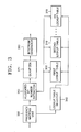
- FIG. 3 is a block diagram of a digital signal encoding apparatus using a plurality of lookup tables according to an embodiment of the present invention.
- the apparatus includes a plurality of lookup tables 300, 310 and 320, a frequency mapping unit 330, a lookup table selector 340, an allocated bit number extractor 350, a quantizer 370, and a bitatream generator 380.
- the plurality of lookup tables 300, 310 and 320 are generated according to characteristics of input signals and store numbers of allocated bits for encoding frequency bands of the input signals in a predetermined number of addresses.
- the characteristic of the input signal can be set to the number of frequency bands among the frequency bands of the input signal, whose occupancy rate is less than or more than a predetermined standard value.
- the occupancy rate of each frequency band can be set to a larger value between an occupancy rate of a square of a scale factor of each frequency band and an occupancy rate of a mean power of each frequency band.
- addresses of the lookup tables are set to values indicating characteristics of the frequency bands.
- each address of the lookup table can be set to a dispersion of each frequency band, a scale factor of each frequency band, a square of a scale factor of each frequency band, a mean value of input signals in each frequency band, a mean power of input signals in each frequency band, a larger value between an occupancy rate of a scale factor of each frequency band and an occupancy rate of a mean value of input signals in each frequency band, or a larger value between an occupancy rate
- scf indicates a scale factor
- mean indicates a mean value
- ch indicates a left channel or a right channel, an occupancy rate of which is calculated in an audio signal
- sb indicates a frequency band having the occupancy rate.
- the frequency mapping unit 330 divides an input signal in the time domain into signals in predetermined frequency bands using a band resolution filter.
- the lookup table selector 340 selects one of the plurality of lookup tables 300, 310 and 320 according to the characteristic of the input signal.
- the characteristic of the input signal considered when the plurality of lookup tables 300, 310 and 320 are generated can be set to the number of frequency bands among the frequency bands of the input signal, whose occupancy rate is less than or more than a predetermined standard value.
- the occupancy rate of each frequency band can be set to a larger value between an occupancy rate of a scale factor of each frequency band and an occupancy rate of a mean value of input signals in each frequency band or a larger value between an occupancy rate of a square of a scale factor of each frequency band and an occupancy rate of a mean power of input signals in each frequency band, which are calculated in Equation 2.
- the allocated bit number extractor 350 calculates address values of the frequency bands of the input signals, extracts numbers of allocated bits corresponding to the calculated address values from the selected lookup table with respect to the frequency bands, and allocates the numbers of bits to the frequency bands.
- the addresses of the frequency bands are set when the plurality of lookup tables 300, 310 and 320 are generated.
- the allocated bit number extractor 350 calculates values indicating characteristics of the frequency bands of the input signals as the address values, and each of the address values can be a dispersion of each frequency band, a scale factor of each frequency band, a square of a scale factor of each frequency band, a mean value of input signals in each frequency band, a mean power of input signals in each frequency band, a larger value between an occupancy rate of a scale factor of each frequency band and an occupancy rate of a mean value of input signals in each frequency band, or a larger value between an occupancy rate of a square of a scale factor of each frequency band and an occupancy rate of a mean power of input signals in each frequency band.
- the quantizer 370 quantizes the input signals using the numbers of bits allocated to the frequency bands.
- the bitstream generator 380 generates a bitstream using the quantized input signals.
- the apparatus can further include a bit number adjuster calculating the number of allocated bits of an entire input signal, which is a sum of the number of bits allocated to each frequency band by the allocated bit number extractor 350, comparing the number of allocated bits of the entire input signal, which is determined by an encoding rate required by the apparatus, and the calculated number of allocated bits, and adjusting the number of bits allocated to each frequency band according to the comparison result.
- a bit number adjuster calculating the number of allocated bits of an entire input signal, which is a sum of the number of bits allocated to each frequency band by the allocated bit number extractor 350, comparing the number of allocated bits of the entire input signal, which is determined by an encoding rate required by the apparatus, and the calculated number of allocated bits, and adjusting the number of bits allocated to each frequency band according to the comparison result.
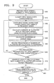
- FIG. 4 is a flowchart of a digital signal encoding method using a plurality of lookup tables according to an embodiment of the present invention.
- the frequency mapping unit 330 converts an input signal in the time domain into signals in predetermined frequency bands using a band resolution filter in operation 400.
- the allocated bit number extractor 350 calculates address values of the frequency bands of the input signals in operation 410.
- the address values of the frequency bands indicate characteristics of frequency bands set as addresses when the plurality of lookup tables 300, 310 and 320 are generated, and each of the address values can be a dispersion of each frequency band, a scale factor of each frequency band, a square of a scale factor of each frequency band, a mean value of input signals in each frequency band, a mean power of input signals in each frequency band, a larger value between an occupancy rate of a scale factor of each frequency band and an occupancy rate of a mean value of input signals in each frequency band, or a larger value between an occupancy rate of a square of a scale factor of each frequency band and an occupancy rate of a mean power of input signals in each frequency band.
- a dispersion characteristic shows how near a distribution of an input signal is distributed with respect to an average distribution. If the dispersion is large, a dynamic area of the input signal is large. Accordingly, to reduce quantization noise, more bits must be allocated. If the dispersion is relatively small, even though the bit allocation amount is small, the quantization noise is not so much generated.
- a mean of an input signal is obtained, the mean value is 0 in a case of a sine wave. Accordingly, a mean power value is used as a characteristic of a frequency band, and more bits are allocated to a frequency band in which a mean power value is large.
- the scale factor is defined as a largest sample value per frequency band, and more bits are allocated to a frequency band in which a scale factor is large.
- the lookup table selector 340 selects one of the plurality of lookup tables 300, 310 and 320 according to the characteristic of the input signal in operation 420.
- the characteristic of the input signal which is a standard of lookup table selection, is considered when the plurality of lookup tables 300, 310 and 320 are generated and can be set to the number of frequency bands among the frequency bands of the input signal, whose occupancy rate is less than or more than a predetermined standard value.
- the occupancy rate of each frequency band can be set to a larger value between an occupancy rate of a scale factor of each frequency band and an occupancy rate of a mean value of input signals in each frequency band or a larger value between an occupancy rate of a square of a scale factor of each frequency band and an occupancy rate of a mean power of input signals in each frequency band, which are calculated in Equation 2.
- the allocated bit number extractor 350 extracts numbers of allocated bits having the address values of frequency bands calculated in operation 410 from the selected lookup table as addresses in operation 430, and allocates the numbers of bits to the frequency bands in operation 440.
- the quantizer 370 quantizes the input signals using the numbers of bits allocated to the frequency bands in operation 450.
- the bitstream generator 380 generates a bitstream using the quantized input signals in operation 460.
- FIG. 5 is a detailed flowchart of a method of allocating the number of allocated bits to each frequency band of FIG. 4. Referring to FIG. 5, numbers of allocated bits of frequency bands extracted from a lookup table are allocated to the frequency bands in operation 500, and the number of bits actually allocated to an entire input signal is calculated by summing the numbers of allocated bits in operation 510.
- the calculated number of bits actually allocated to the entire input signal is equal to the number of required bits determined by a compression ratio required by encoding, for example, the number of entire bits of the input signal is 100 and the number of required bits is 50 when the compression ratio is 50%, in operation 520. If the number of allocated bits is equal to the number of required bits, as many bits as the numbers of bits allocated in operation 500 are allocated to frequency bands.
- the number of allocated bits is not equal to the number of required bits, it is determined whether the number of allocated bits is larger than the number of required bits in operation 530. If the number of allocated bits is larger than the number of required bits, in operation 540, examination is performed from the highest frequency band, and a band whose occupancy rate is lowest and to which more than one bit is allocated is decreased by eliminating one bit until the number of allocated bits is equal to the number of required bits.
- all bands are evenly decreased by designating a lowest priority to the one bit decreased band. Also, decrease from a high frequency band is because important information is mainly concentrated in low frequencies.
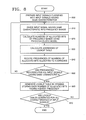
- FIG. 6 is a detailed flowchart of a method of selecting one of a plurality of lookup tables of FIG. 4.
- a scale factor of each frequency band and a mean power of input signals in each frequency band are calculated in operation 600, and an occupancy rate of a square of a scale factor of each frequency band and an occupancy rate of a mean power of input signals in each frequency band are calculated as shown in Equation 2 in operation 610.
- a larger value between the calculated occupancy rates is selected as an occupancy rate of each frequency band in operation 620.
- the number of frequency bands (LP) of which the selected occupancy rate is lower than a predetermined occupancy rate and the number of frequency bands (HP) of which the selected occupancy rate is higher than the predetermined occupancy rate are calculated in operation 630.
- One of a plurality of lookup tables is selected according to the numbers of frequency bands (LP and HP) calculated in operation 630, which are representing a characteristic of an input signal, in operation 640. If the number of frequency bands (LP) of which an occupancy rate is lower than the predetermined occupancy rate is large, input signals are concentratedly distributed in a specific frequency band. Accordingly, a lookup table in which more bits are allocated to frequency bands where input signals are distributed is selected. Also, if the number of frequency bands (HP) of which the selected occupancy rate is higher than the predetermined occupancy rate is small, input signals are concentratedly distributed in a specific frequency band. Accordingly, a lookup table in which more bits are allocated to frequency bands where input signals are distributed is selected.
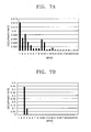
- FIGS. 7A and 7B are graphs showing occupancy rates of frequency bands of input signals.
- FIG. 7A shows input signals having a general characteristic. Referring to FIG. 7A, since LP is small and HP is large, a lookup table in which allocated bits are evenly distributed in every frequency band is selected.
- FIG. 7B shows input signals having a characteristic concentrated in a specific frequency band.
- LP is large and HP is small
- a lookup table in which many allocated bits are stored in a specific frequency band is selected.
- FIG. 8 is a flowchart of a method generating a plurality of lookup tables according to a first embodiment of the present invention.
- a predetermined number of input signals having various signal characteristics and classified into signals having same signal characteristics are prepared in operation 800.
- the characteristic of the input signal can be the number of frequency bands among the frequency bands of the input signal, whose occupancy rate is less or more than a predetermined standard value.
- the occupancy rate of each frequency band can be set to a larger value between an occupancy rate of a scale factor of each frequency band and an occupancy rate of a mean value of input signals in each frequency band or a larger value between an occupancy rate of a square of a scale factor of each frequency band and an occupancy rate of a mean power of input signals in each frequency band, which are calculated in Equation 2.
- One characteristic of the characteristics of the input signals is selected, and one of input signals having the selected characteristic is divided into frequency bands in operation 810. With respect to the input signal, the number of allocated bits of each frequency band is calculated using a psychoacoustic model in operation 820. Since a method of calculating the number of allocated bits is the same as an operation of the psychoacoustic model 110 shown in FIG. 1, description of the method is omitted.
- Address values of frequency bands of the input signal are calculated in operation 830.
- the address values can be set to values indicating characteristics of the frequency bands of the input signal, and each value can be calculated by being set to a dispersion of each frequency band, a scale factor of each frequency band, a square of a scale factor of each frequency band, a mean value of input signals in each frequency band, a mean power of input signals in each frequency band, a larger value between an occupancy rate of a scale factor of each frequency band and an occupancy rate of a mean value of input signals in each frequency band, or a larger value between an occupancy rate of a square of a scale factor of each frequency band and an occupancy rate of a mean power of input signals in each frequency band.
- the numbers of allocated bits calculated in operation 820 are stored in respective addresses having the address values of frequency bands calculated in operation 830, and frequencies that the numbers of allocated bits are stored in the respective addresses are recorded in operation 840.
- a lookup table is generated by storing each value having a largest frequency among the numbers of allocated bits stored in each address of each frequency band as the number of allocated bits in operation 860.
- the size of the lookup table can be reduced by excluding addresses of which the number of allocated bits is 0 from the generated lookup table or storing only addresses, in which the number of allocated bits is changed, in the generated lookup table when the numbers of allocated bits of consecutive addresses are the same.
- FIG. 9 is a flowchart of a method generating a plurality of lookup tables according to a second embodiment of the present invention.
- a predetermined number of input signals having various characteristics are prepared in operation 900.
- the input signals are classified according to a predetermined number of characteristics in operation 910.
- the characteristic of the input signal can be the number of frequency bands, whose occupancy rate is less or more than a predetermined standard value, among the frequency bands of the input signal.
- the occupancy rate of each frequency band can be set to a larger value between an occupancy rate of a scale factor of each frequency band and an occupancy rate of a mean value of input signals in each frequency band or a larger value between an occupancy rate of a square of a scale factor of each frequency band and an occupancy rate of a mean power of input signals in each frequency band, which are calculated in Equation 2.
- One characteristic of the classified characteristics of the input signals is selected, and one of input signals having the selected characteristic is divided into frequency bands in operation 920.
- the number of allocated bits to each frequency band is calculated using a psychoacoustic model in operation 930. Since a method of calculating the number of allocated bits is the same as an operation of the psychoacoustic model 110 shown in FIG. 1, description of the method is omitted.
- Address values of frequency bands of the input signal are calculated in operation 940.
- the address values can be set to values indicating characteristics of the frequency bands of the input signal, and each value can be calculated by being set to a dispersion of each frequency band, a scale factor of each frequency band, a square of a scale factor of each frequency band, a mean value of input signals in each frequency band, a mean power of input signals in each frequency band, a larger value between an occupancy rate of a scale factor of each frequency band and an occupancy rate of a mean value of input signals in each frequency band, or a larger value between an occupancy rate of a square of a scale factor of each frequency band and an occupancy rate of a mean power of input signals in each frequency band.
- the numbers of allocated bits calculated in operation 930 are stored in respective addresses having the address values of frequency bands calculated in operation 940, and frequencies that the numbers of allocated bits are stored in the respective addresses are recorded in operation 950.
- operations 920 through 950 are performed for all input signals having the selected characteristic, operations 920 through 950 are repeated in operation 960.
- a lookup table is generated by storing each value having a largest frequency among the numbers of allocated bits stored in each address of each frequency band as the number of allocated bits in operation 970.
- the size of the lookup table can be reduced by excluding addresses of which the number of allocated bits is 0 from the generated lookup table or storing only addresses, in which the number of allocated bits is changed, in the generated lookup table when the numbers of allocated bits of consecutive addresses are the same.
- FIG. 10 is an example of a method of setting addresses of a lookup table.
- the setting method shown in FIG. 10 uses a larger value between an occupancy rate of a square of a scale factor of each frequency band and an occupancy rate of a mean power of each frequency band as each address of the lookup table. All occupancy rates, which are respective addresses of the lookup table, have values between 0 and 1, and the occupancy rates between 0 and 1 are set to 127 addresses.
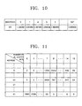
- FIG. 11 is a table illustrating an example of a method of generating a lookup table.
- the generating method shown in FIG. 11 is a method of generating a lookup table using frequencies of the numbers of allocated bits in operation 860 of FIG. 8 or in operation 970 of FIG. 9.
- the number of allocated bits per address for one frequency band is stored in a lookup table.
- 8 having a highest frequency is stored as the final number of allocated bits in a case of an address 5
- 7 having a highest frequency is stored as the final number of allocated bits in a case of an address 30, and 0 having a highest frequency is stored as the final number of allocated bits in a case of an address 61.
- addresses of which the number of allocated bits is 0 can be excluded from the lookup table, or when the numbers of allocated bits of consecutive addresses are the same, only addresses in which the number of allocated bits is changed can be stored in the lookup table.
- the invention can also be embodied as computer readable codes on a computer readable recording medium.
- the computer readable recording medium is any data storage device that can store data which can be thereafter read by a computer system. Examples of the computer readable recording medium include read-only memory (ROM), random-access memory (RAM), CD-ROMs, magnetic tapes, floppy disks, optical data storage devices, and carrier waves (such as data transmission through the Internet).
- bit amount control suitable for a characteristic of an input signal can be performed by extracting numbers of allocated bits of frequency bands from an optimal lookup table selected according to the characteristic of the input signal. Also, an additional computational amount can be reduced by using each occupancy rate per frequency band equal to each address of the lookup table as the characteristic of the input signal.
Landscapes
- Engineering & Computer Science (AREA)
- Physics & Mathematics (AREA)
- Spectroscopy & Molecular Physics (AREA)
- Computational Linguistics (AREA)
- Chemical & Material Sciences (AREA)
- Signal Processing (AREA)
- Health & Medical Sciences (AREA)
- Audiology, Speech & Language Pathology (AREA)
- Human Computer Interaction (AREA)
- Acoustics & Sound (AREA)
- Multimedia (AREA)
- Organic Chemistry (AREA)
- Oil, Petroleum & Natural Gas (AREA)
- Mechanical Engineering (AREA)
- Compression, Expansion, Code Conversion, And Decoders (AREA)
Applications Claiming Priority (2)
| Application Number | Priority Date | Filing Date | Title |
|---|---|---|---|
| KR1020040033381A KR100723400B1 (ko) | 2004-05-12 | 2004-05-12 | 복수의 룩업테이블을 이용한 디지털 신호 부호화 방법 및장치 |
| KR2004033381 | 2004-05-12 |
Publications (2)
| Publication Number | Publication Date |
|---|---|
| EP1596366A1 true EP1596366A1 (fr) | 2005-11-16 |
| EP1596366B1 EP1596366B1 (fr) | 2007-06-06 |
Family
ID=34940618
Family Applications (1)
| Application Number | Title | Priority Date | Filing Date |
|---|---|---|---|
| EP05251759A Active EP1596366B1 (fr) | 2004-05-12 | 2005-03-22 | Dispositif de codage d'un signal numérique et appareil associé utilisant une pluralité de tables à consulter |
Country Status (5)
| Country | Link |
|---|---|
| US (1) | US7650278B2 (fr) |
| EP (1) | EP1596366B1 (fr) |
| JP (1) | JP4628861B2 (fr) |
| KR (1) | KR100723400B1 (fr) |
| DE (1) | DE602005001291T2 (fr) |
Cited By (1)
| Publication number | Priority date | Publication date | Assignee | Title |
|---|---|---|---|---|
| EP1600946A1 (fr) | 2004-05-28 | 2005-11-30 | Samsung Electronics Co., Ltd. | Procédé et dispositif pour le codage/décodage d'un signal numérique |
Families Citing this family (10)
| Publication number | Priority date | Publication date | Assignee | Title |
|---|---|---|---|---|
| JP2007183528A (ja) * | 2005-12-06 | 2007-07-19 | Fujitsu Ltd | 符号化装置、符号化方法、および符号化プログラム |
| US20070230598A1 (en) * | 2006-03-30 | 2007-10-04 | Yi-Hsiu Wang | OFDMA transmitter and method of transmitting OFDMA signals using compress-decompress modulation |
| KR100918115B1 (ko) * | 2007-09-28 | 2009-09-22 | 한국전자통신연구원 | 룩업 테이블에 기초한 복수 개의 가변소자 제어 방법 |
| WO2009059631A1 (fr) * | 2007-11-06 | 2009-05-14 | Nokia Corporation | Appareil de codage audio et procédé associé |
| KR101238239B1 (ko) * | 2007-11-06 | 2013-03-04 | 노키아 코포레이션 | 인코더 |
| US8264975B2 (en) * | 2008-02-20 | 2012-09-11 | Qualcomm Incorporated | FFT-based estimation of thermal noise and rise over thermal in a wireless communication system |
| WO2012081166A1 (fr) * | 2010-12-14 | 2012-06-21 | パナソニック株式会社 | Dispositif de codage, dispositif de décodage et procédés associés |
| CN106409299B (zh) | 2012-03-29 | 2019-11-05 | 华为技术有限公司 | 信号编码和解码的方法和设备 |
| EP3975173B1 (fr) | 2013-12-02 | 2024-01-17 | Top Quality Telephony, Llc | Support de stockage lisible par ordinateur et produit logiciel informatique |
| CN108469560B (zh) * | 2018-03-16 | 2020-01-14 | 武汉大学 | 一种基于快速s变换时频空间模型的电磁干扰客观复杂度评估方法 |
Citations (2)
| Publication number | Priority date | Publication date | Assignee | Title |
|---|---|---|---|---|
| US5732391A (en) * | 1994-03-09 | 1998-03-24 | Motorola, Inc. | Method and apparatus of reducing processing steps in an audio compression system using psychoacoustic parameters |
| US5864802A (en) * | 1995-09-22 | 1999-01-26 | Samsung Electronics Co., Ltd. | Digital audio encoding method utilizing look-up table and device thereof |
Family Cites Families (19)
| Publication number | Priority date | Publication date | Assignee | Title |
|---|---|---|---|---|
| JPH06252773A (ja) * | 1993-02-27 | 1994-09-09 | Sony Corp | 高能率符号化装置 |
| KR100300957B1 (ko) | 1995-09-22 | 2001-11-22 | 윤종용 | 룩업테이블을이용한디지탈오디오부호화방법및장치 |
| KR100300956B1 (ko) | 1995-09-22 | 2001-11-22 | 윤종용 | 룩업테이블을이용한디지탈오디오부호화방법및장치 |
| JP3519859B2 (ja) * | 1996-03-26 | 2004-04-19 | 三菱電機株式会社 | 符号器及び復号器 |
| JPH1055200A (ja) * | 1996-08-12 | 1998-02-24 | Nippon Telegr & Teleph Corp <Ntt> | 音声適応形符号化装置及び復号化装置 |
| JPH10240297A (ja) * | 1996-12-27 | 1998-09-11 | Mitsubishi Electric Corp | 音響信号符号化装置 |
| KR100255861B1 (ko) * | 1997-08-30 | 2000-05-01 | 윤종용 | 복수의 룩업테이블을 이용한 입력 및 출력화상 처리방법과 그 장치 |
| JP2000091920A (ja) * | 1998-09-08 | 2000-03-31 | Hitachi Ltd | 画像音声圧縮装置 |
| US6195633B1 (en) * | 1998-09-09 | 2001-02-27 | Sony Corporation | System and method for efficiently implementing a masking function in a psycho-acoustic modeler |
| US6240379B1 (en) * | 1998-12-24 | 2001-05-29 | Sony Corporation | System and method for preventing artifacts in an audio data encoder device |
| TW477119B (en) * | 1999-01-28 | 2002-02-21 | Winbond Electronics Corp | Byte allocation method and device for speech synthesis |
| US6529634B1 (en) | 1999-11-08 | 2003-03-04 | Qualcomm, Inc. | Contrast sensitive variance based adaptive block size DCT image compression |
| JP2001249699A (ja) * | 2000-03-07 | 2001-09-14 | Hitachi Ltd | 音声圧縮装置 |
| JP2002006895A (ja) * | 2000-06-20 | 2002-01-11 | Fujitsu Ltd | ビット割当装置および方法 |
| US6728669B1 (en) | 2000-08-07 | 2004-04-27 | Lucent Technologies Inc. | Relative pulse position in celp vocoding |
| US6882976B1 (en) * | 2001-02-28 | 2005-04-19 | Advanced Micro Devices, Inc. | Efficient finite length POW10 calculation for MPEG audio encoding |
| CA2354755A1 (fr) * | 2001-08-07 | 2003-02-07 | Dspfactory Ltd. | Amelioration de l'intelligibilite des sons a l'aide d'un modele psychoacoustique et d'un banc de filtres surechantillonne |
| KR100695125B1 (ko) * | 2004-05-28 | 2007-03-14 | 삼성전자주식회사 | 디지털 신호 부호화/복호화 방법 및 장치 |
| US7292163B1 (en) * | 2006-04-14 | 2007-11-06 | Xilinx, Inc. | Circuit for and method of encoding a data stream |
-
2004
- 2004-05-12 KR KR1020040033381A patent/KR100723400B1/ko active IP Right Grant
-
2005
- 2005-03-16 US US11/080,409 patent/US7650278B2/en active Active
- 2005-03-22 EP EP05251759A patent/EP1596366B1/fr active Active
- 2005-03-22 DE DE602005001291T patent/DE602005001291T2/de active Active
- 2005-05-12 JP JP2005139801A patent/JP4628861B2/ja active Active
Patent Citations (2)
| Publication number | Priority date | Publication date | Assignee | Title |
|---|---|---|---|---|
| US5732391A (en) * | 1994-03-09 | 1998-03-24 | Motorola, Inc. | Method and apparatus of reducing processing steps in an audio compression system using psychoacoustic parameters |
| US5864802A (en) * | 1995-09-22 | 1999-01-26 | Samsung Electronics Co., Ltd. | Digital audio encoding method utilizing look-up table and device thereof |
Non-Patent Citations (1)
| Title |
|---|
| OH H-O ET AL: "Low power MPEG/audio encoders using simplified psychoacoustic model and fast bit allocation", INTERNATIONAL CONFERENCE ON CONSUMER ELECTRONICS. 2001 DIGEST OF TECHNICAL PAPERS. ICCE. LOS ANGELES, CA, JUNE 19 - 21, 2001, NEW YORK, NY : IEEE, US, 19 June 2001 (2001-06-19), pages 320 - 321, XP010552184, ISBN: 0-7803-6622-0 * |
Cited By (4)
| Publication number | Priority date | Publication date | Assignee | Title |
|---|---|---|---|---|
| EP1600946A1 (fr) | 2004-05-28 | 2005-11-30 | Samsung Electronics Co., Ltd. | Procédé et dispositif pour le codage/décodage d'un signal numérique |
| EP1600946B1 (fr) * | 2004-05-28 | 2009-11-18 | Samsung Electronics Co., Ltd. | Procédé et dispositif pour le codage d'un signal audio numérique |
| US7752041B2 (en) | 2004-05-28 | 2010-07-06 | Samsung Electronics Co., Ltd. | Method and apparatus for encoding/decoding digital signal |
| CN1702974B (zh) * | 2004-05-28 | 2012-01-25 | 三星电子株式会社 | 用于对数字信号编码/解码的方法和设备 |
Also Published As
| Publication number | Publication date |
|---|---|
| KR100723400B1 (ko) | 2007-05-30 |
| US20050254588A1 (en) | 2005-11-17 |
| JP2005328542A (ja) | 2005-11-24 |
| US7650278B2 (en) | 2010-01-19 |
| DE602005001291D1 (de) | 2007-07-19 |
| EP1596366B1 (fr) | 2007-06-06 |
| KR20050108180A (ko) | 2005-11-16 |
| JP4628861B2 (ja) | 2011-02-09 |
| DE602005001291T2 (de) | 2008-02-07 |
Similar Documents
| Publication | Publication Date | Title |
|---|---|---|
| EP1596366B1 (fr) | Dispositif de codage d'un signal numérique et appareil associé utilisant une pluralité de tables à consulter | |
| US8615391B2 (en) | Method and apparatus to extract important spectral component from audio signal and low bit-rate audio signal coding and/or decoding method and apparatus using the same | |
| FI84538C (fi) | Foerfarande foer transmission av digitaliska audiosignaler. | |
| JP5175028B2 (ja) | デジタル信号の符号化方法及び装置ならびに復号化方法及び装置 | |
| KR100288460B1 (ko) | 신호가중된 양자화비트할당을 사용하는 데이타 압축 장치 및 방법 | |
| JP3274285B2 (ja) | オーディオ信号の符号化方法 | |
| KR100991448B1 (ko) | 스펙트럼 홀 충전을 사용하는 오디오 코딩 시스템 | |
| US5684922A (en) | Encoding and decoding apparatus causing no deterioration of sound quality even when sine-wave signal is encoded | |
| JP3153933B2 (ja) | データ符号化装置及び方法並びにデータ復号化装置及び方法 | |
| KR20090110244A (ko) | 오디오 시맨틱 정보를 이용한 오디오 신호의 부호화/복호화 방법 및 그 장치 | |
| KR101803410B1 (ko) | 인코딩 방법 및 장치 | |
| JP4021124B2 (ja) | デジタル音響信号符号化装置、方法及び記録媒体 | |
| JP3927627B2 (ja) | ディジタル・オーディオ符号化方法 | |
| EP1170727A2 (fr) | Codeur audio avec allocation psychacoustisque des bits | |
| KR0137472B1 (ko) | 오디오 신호 코딩 방법 | |
| US7613609B2 (en) | Apparatus and method for encoding a multi-channel signal and a program pertaining thereto | |
| KR100300957B1 (ko) | 룩업테이블을이용한디지탈오디오부호화방법및장치 | |
| JPH07295594A (ja) | オーディオ信号符号化方法 | |
| JP3134384B2 (ja) | 符号化装置及び方法 | |
| KR100351772B1 (ko) | 디지털부호화장치,디지털기록신호도출장치및디지털신호데이터도출방법 | |
| KR100590340B1 (ko) | 디지털 오디오 부호화 방법 및 장치 | |
| KR100300956B1 (ko) | 룩업테이블을이용한디지탈오디오부호화방법및장치 | |
| JP2000148191A (ja) | ディジタルオーディオ信号の符号化装置 | |
| JPH08167247A (ja) | 高能率符号化方法及び装置、並びに伝送媒体 |
Legal Events
| Date | Code | Title | Description |
|---|---|---|---|
| PUAI | Public reference made under article 153(3) epc to a published international application that has entered the european phase |
Free format text: ORIGINAL CODE: 0009012 |
|
| AK | Designated contracting states |
Kind code of ref document: A1 Designated state(s): AT BE BG CH CY CZ DE DK EE ES FI FR GB GR HU IE IS IT LI LT LU MC NL PL PT RO SE SI SK TR |
|
| AX | Request for extension of the european patent |
Extension state: AL BA HR LV MK YU |
|
| 17P | Request for examination filed |
Effective date: 20060315 |
|
| AKX | Designation fees paid |
Designated state(s): DE FR GB |
|
| 17Q | First examination report despatched |
Effective date: 20060705 |
|
| GRAP | Despatch of communication of intention to grant a patent |
Free format text: ORIGINAL CODE: EPIDOSNIGR1 |
|
| GRAS | Grant fee paid |
Free format text: ORIGINAL CODE: EPIDOSNIGR3 |
|
| GRAA | (expected) grant |
Free format text: ORIGINAL CODE: 0009210 |
|
| AK | Designated contracting states |
Kind code of ref document: B1 Designated state(s): DE FR GB |
|
| REG | Reference to a national code |
Ref country code: GB Ref legal event code: FG4D |
|
| REF | Corresponds to: |
Ref document number: 602005001291 Country of ref document: DE Date of ref document: 20070719 Kind code of ref document: P |
|
| ET | Fr: translation filed | ||
| PLBE | No opposition filed within time limit |
Free format text: ORIGINAL CODE: 0009261 |
|
| STAA | Information on the status of an ep patent application or granted ep patent |
Free format text: STATUS: NO OPPOSITION FILED WITHIN TIME LIMIT |
|
| 26N | No opposition filed |
Effective date: 20080307 |
|
| REG | Reference to a national code |
Ref country code: FR Ref legal event code: PLFP Year of fee payment: 12 |
|
| REG | Reference to a national code |
Ref country code: FR Ref legal event code: PLFP Year of fee payment: 13 |
|
| REG | Reference to a national code |
Ref country code: FR Ref legal event code: PLFP Year of fee payment: 14 |
|
| PGFP | Annual fee paid to national office [announced via postgrant information from national office to epo] |
Ref country code: FR Payment date: 20230221 Year of fee payment: 19 |
|
| P01 | Opt-out of the competence of the unified patent court (upc) registered |
Effective date: 20230519 |
|
| PGFP | Annual fee paid to national office [announced via postgrant information from national office to epo] |
Ref country code: DE Payment date: 20240220 Year of fee payment: 20 Ref country code: GB Payment date: 20240222 Year of fee payment: 20 |