EP1595836B1 - Device for processing stacks of electrostatic rechargeable flat parts - Google Patents
Device for processing stacks of electrostatic rechargeable flat parts Download PDFInfo
- Publication number
- EP1595836B1 EP1595836B1 EP05015721A EP05015721A EP1595836B1 EP 1595836 B1 EP1595836 B1 EP 1595836B1 EP 05015721 A EP05015721 A EP 05015721A EP 05015721 A EP05015721 A EP 05015721A EP 1595836 B1 EP1595836 B1 EP 1595836B1
- Authority
- EP
- European Patent Office
- Prior art keywords
- sheets
- electrostatic
- blowing
- suction
- cutting
- Prior art date
- Legal status (The legal status is an assumption and is not a legal conclusion. Google has not performed a legal analysis and makes no representation as to the accuracy of the status listed.)
- Active
Links
Images
Classifications
-
- B—PERFORMING OPERATIONS; TRANSPORTING
- B65—CONVEYING; PACKING; STORING; HANDLING THIN OR FILAMENTARY MATERIAL
- B65H—HANDLING THIN OR FILAMENTARY MATERIAL, e.g. SHEETS, WEBS, CABLES
- B65H29/00—Delivering or advancing articles from machines; Advancing articles to or into piles
- B65H29/16—Delivering or advancing articles from machines; Advancing articles to or into piles by contact of one face only with moving tapes, bands, or chains
- B65H29/18—Delivering or advancing articles from machines; Advancing articles to or into piles by contact of one face only with moving tapes, bands, or chains and introducing into a pile
-
- B—PERFORMING OPERATIONS; TRANSPORTING
- B65—CONVEYING; PACKING; STORING; HANDLING THIN OR FILAMENTARY MATERIAL
- B65H—HANDLING THIN OR FILAMENTARY MATERIAL, e.g. SHEETS, WEBS, CABLES
- B65H39/00—Associating, collating, or gathering articles or webs
- B65H39/16—Associating two or more webs
-
- B—PERFORMING OPERATIONS; TRANSPORTING
- B65—CONVEYING; PACKING; STORING; HANDLING THIN OR FILAMENTARY MATERIAL
- B65H—HANDLING THIN OR FILAMENTARY MATERIAL, e.g. SHEETS, WEBS, CABLES
- B65H29/00—Delivering or advancing articles from machines; Advancing articles to or into piles
- B65H29/24—Delivering or advancing articles from machines; Advancing articles to or into piles by air blast or suction apparatus
- B65H29/241—Suction devices
- B65H29/242—Suction bands or belts
-
- B—PERFORMING OPERATIONS; TRANSPORTING
- B65—CONVEYING; PACKING; STORING; HANDLING THIN OR FILAMENTARY MATERIAL
- B65H—HANDLING THIN OR FILAMENTARY MATERIAL, e.g. SHEETS, WEBS, CABLES
- B65H35/00—Delivering articles from cutting or line-perforating machines; Article or web delivery apparatus incorporating cutting or line-perforating devices, e.g. adhesive tape dispensers
- B65H35/0006—Article or web delivery apparatus incorporating cutting or line-perforating devices
-
- B—PERFORMING OPERATIONS; TRANSPORTING
- B65—CONVEYING; PACKING; STORING; HANDLING THIN OR FILAMENTARY MATERIAL
- B65H—HANDLING THIN OR FILAMENTARY MATERIAL, e.g. SHEETS, WEBS, CABLES
- B65H35/00—Delivering articles from cutting or line-perforating machines; Article or web delivery apparatus incorporating cutting or line-perforating devices, e.g. adhesive tape dispensers
- B65H35/04—Delivering articles from cutting or line-perforating machines; Article or web delivery apparatus incorporating cutting or line-perforating devices, e.g. adhesive tape dispensers from or with transverse cutters or perforators
-
- B—PERFORMING OPERATIONS; TRANSPORTING
- B65—CONVEYING; PACKING; STORING; HANDLING THIN OR FILAMENTARY MATERIAL
- B65H—HANDLING THIN OR FILAMENTARY MATERIAL, e.g. SHEETS, WEBS, CABLES
- B65H5/00—Feeding articles separated from piles; Feeding articles to machines
- B65H5/004—Feeding articles separated from piles; Feeding articles to machines using electrostatic force
-
- B—PERFORMING OPERATIONS; TRANSPORTING
- B65—CONVEYING; PACKING; STORING; HANDLING THIN OR FILAMENTARY MATERIAL
- B65H—HANDLING THIN OR FILAMENTARY MATERIAL, e.g. SHEETS, WEBS, CABLES
- B65H2301/00—Handling processes for sheets or webs
- B65H2301/40—Type of handling process
- B65H2301/42—Piling, depiling, handling piles
- B65H2301/421—Forming a pile
- B65H2301/4212—Forming a pile of articles substantially horizontal
-
- B—PERFORMING OPERATIONS; TRANSPORTING
- B65—CONVEYING; PACKING; STORING; HANDLING THIN OR FILAMENTARY MATERIAL
- B65H—HANDLING THIN OR FILAMENTARY MATERIAL, e.g. SHEETS, WEBS, CABLES
- B65H2301/00—Handling processes for sheets or webs
- B65H2301/40—Type of handling process
- B65H2301/44—Moving, forwarding, guiding material
- B65H2301/443—Moving, forwarding, guiding material by acting on surface of handled material
- B65H2301/4433—Moving, forwarding, guiding material by acting on surface of handled material by means holding the material
- B65H2301/44334—Moving, forwarding, guiding material by acting on surface of handled material by means holding the material using electrostatic forces
-
- B—PERFORMING OPERATIONS; TRANSPORTING
- B65—CONVEYING; PACKING; STORING; HANDLING THIN OR FILAMENTARY MATERIAL
- B65H—HANDLING THIN OR FILAMENTARY MATERIAL, e.g. SHEETS, WEBS, CABLES
- B65H2301/00—Handling processes for sheets or webs
- B65H2301/50—Auxiliary process performed during handling process
- B65H2301/51—Modifying a characteristic of handled material
- B65H2301/513—Modifying electric properties
- B65H2301/5132—Bringing electrostatic charge
-
- B—PERFORMING OPERATIONS; TRANSPORTING
- B65—CONVEYING; PACKING; STORING; HANDLING THIN OR FILAMENTARY MATERIAL
- B65H—HANDLING THIN OR FILAMENTARY MATERIAL, e.g. SHEETS, WEBS, CABLES
- B65H2301/00—Handling processes for sheets or webs
- B65H2301/50—Auxiliary process performed during handling process
- B65H2301/51—Modifying a characteristic of handled material
- B65H2301/513—Modifying electric properties
- B65H2301/5133—Removing electrostatic charge
-
- B—PERFORMING OPERATIONS; TRANSPORTING
- B65—CONVEYING; PACKING; STORING; HANDLING THIN OR FILAMENTARY MATERIAL
- B65H—HANDLING THIN OR FILAMENTARY MATERIAL, e.g. SHEETS, WEBS, CABLES
- B65H2301/00—Handling processes for sheets or webs
- B65H2301/50—Auxiliary process performed during handling process
- B65H2301/53—Auxiliary process performed during handling process for acting on performance of handling machine
- B65H2301/532—Modifying characteristics of surface of parts in contact with handled material
- B65H2301/5322—Generating electrostatic charge at said surface
Abstract
Description
Die Erfindung betrifft eine Vorrichtung zur Verarbeitung einer mehrlagigen elektrostatisch aufladbaren Materialbahn zu einzelnen übereinanderliegenden Bögen, mit einer Fördervorrichtung zum Transport der Bögen, einer elektrostatischen Entladungsvorrichtung zur elektrostatischen Entladung der Bögen und einer stromabwärts von der Fördervorrichtung gelegenen Stapelablage zur Bildung von Stapeln aus den übereinanderliengenden Bögen, wobei die elektrostatische Entladungsvorrichtung im Bereich der Stapelablage angeordnet ist und eine Einrichtung zum elektrostatischen Aufladen von Druckluft mit gegenüber den Bögen entgegengesetzter Polarität und eine Blasvorrichtung zum Blasen dieser Luft gegen die Bögen aufweist.The invention relates to an apparatus for processing a multilayer electrostatically chargeable web into individual superimposed sheets, comprising a conveyor for transporting the sheets, an electrostatic discharge device for electrostatically discharging the sheets, and a stack tray located downstream of the conveyor for forming stacks of the overlying sheets; wherein the electrostatic discharge device is arranged in the region of the stack tray and has a device for electrostatically charging compressed air with opposite polarity to the sheets and a blowing device for blowing this air against the sheets.
Beim Transport einer mehrlagigen Materialbahn oder von daraus geschnittenen übereinanderliegenden Bögen in der papierverarbeitenden Industrie, beispielsweise von einer Bearbeitungsstation zu einer anderen, zu einer Stapelablage oder zu einer Verpackungsmaschine, sind die Bögen aufgrund von Beschleunigungen oder Verzögerungen durch die Fördervorrichtungen, Abzweigungen u. dgl. im besonderen Maße gefährdet. Insbesondere bei hohen Beschleunigungen und abrupten Richtungsänderungen des Transportweges können die übereinanderliegenden Bögen in sich verrutschen. Deshalb sind schon an die Transportweise und die Ausbildung der Fördervorrichtungen hohe Anforderungen zu stellen; denn verrutschte, außer Form geratene Bogenstapel lassen sich einer Weiterverarbeitung oder Verpackung nicht zuführen. Deshalb wird z.B. in der
Sofern die mehrlagige Materialbahn nicht durch elektrostatische Aufladungsvorrichtungen gezielt elektrostatisch aufgeladen wird, können die während des weiteren Verarbeitungsprozesses stattfindenden Relativbewegungen zwischen Maschinenkomponenten und dem Material und/oder innerhalb des Materials in Abhängigkeit von dem Material und den Umgebungsbedingungen zu elektrostatischen Aufladungen führen. Diese elektrostatischen Aufladungen können den weiteren Verarbeitungsprozess in einer nachfolgenden Vorrichtung behindern. Für die Neutralisierung des elektrostatisch aufgeladenen Materials sind z.B. im Bereich der Fördervorrichtung fest über die gesamte Arbeitsbreite installierte Antistatikeinheiten bekannt, die versuchen, das an ihnen vorbeilaufende Material zu entladen. Die kurze Verweilzeit des Materials unter diesen Antistatikeinheiten während des Transportes führt jedoch nicht zu der gewünschten vollständigen Entladung. Außerdem neigt das Material auf seinem weiteren Weg zur Stapelablage dazu, sich wieder aufzuladen.Unless the multilayer web is electrostatically charged by electrostatic charging devices, the relative movements between machine components and the material and / or within the material occurring during the further processing may result in electrostatic charges depending on the material and environmental conditions. These electrostatic charges may hinder the further processing in a subsequent device. For the neutralization of the electrostatically charged material, e.g. In the area of the conveyor device, anti-statics units installed fixedly over the entire working width are known which attempt to unload the material passing by them. However, the short residence time of the material under these antistatic units during transport does not result in the desired complete discharge. In addition, the material tends to recharge on its way to the stacker tray.
Deshalb wird in der
Die Erfindung schlägt nun vor, bei einer Vorrichtung der eingangs genannten Art die Einrichtung zum elektrostatischen Aufladen von Druckluft mit gegenüber den Bögen entgegengesetzte Polarität und die Blasvorrichtung zum Blasen dieser Luft gegen die Bögen in einem Gehäuse anzuordnen, dessen einer Abschnitt die Stapelablage begrenzt, einen Anschlag für die Stapel bildet und die Blasvorrichtung aufweist.The invention now proposes to arrange in a device of the type mentioned the means for electrostatic charging of compressed air with respect to the arcs opposite polarity and the blowing device for blowing this air against the sheets in a housing whose one section limits the stack tray, a stop forms for the stack and having the blowing device.
Durch die erfindungsgemäße Anordnung wird Blasluft mit elektrostatisch entladender Wirkung gezielt in den Stapelbereich eingebracht. Hierdurch lassen sich gleichzeitig zwei Effekte in vorteilhafter Weise miteinander kombinieren. Zum einen wird eine elektrostatische Neutralisierung der Bögen bewirkt. Zum anderen wird zwischen den absinkenden Bögen in der Stapelablage ein Luftpolster erzeugt, welches in Verbindung mit dem die Stapelablage begrenzenden Abschnitt des Gehäuses, das einen Anschlag für die Stapel bildet, für eine exakte Kantenbildung des entstehenden Stapels sorgt.By means of the arrangement according to the invention, blown air with an electrostatically discharging action is deliberately introduced into the stack area. In this way, two effects can be combined with each other in an advantageous manner at the same time. On the one hand, an electrostatic neutralization of the sheets is effected. On the other hand, an air cushion is produced between the sinking sheets in the stack tray, which, in conjunction with the portion of the housing which delimits the stack tray, which forms a stop for the stacks, ensures that the resulting stack forms an exact edge.
Zwar offenbart die
Insbesondere ist die elektrostatische Entladungsvorrichtung im stromaufwärtigen Abschnitt, vorzugsweise an der stromaufwärtigen Seite, der Stapelablage angeordnet.In particular, the electrostatic discharge device is disposed in the upstream portion, preferably on the upstream side, of the stack tray.
Vorzugsweise bläst die Blasvorrichtung die Luft im Wesentlichen gegen die nachlaufenden Ränder der Bögen.Preferably, the blowing device blows the air substantially against the trailing edges of the sheets.
Zweckmäßigerweise weist die Blasvorrichtung eine Düsenanordnung auf.Expediently, the blowing device has a nozzle arrangement.
Bei einer weiteren bevorzugten Ausführung der Erfindung kann der die Stapelablage begrenzende Abschnitt des Gehäuses mit Öffnungen für das Ausblasen der Luft versehen sein. Diese Öffnungen sind derart gestaitet, dass sie eine Beschleunigung der austretenden Luft mit elektrostatisch entladender Wirkung in Richtung auf den sich bildenden Stapel ermöglichen.In a further preferred embodiment of the invention, the portion of the housing defining the stack tray can be provided with openings for the blowing out of the air. These openings are stiffened so that they allow an acceleration of the exiting air with an electrostatic discharge effect in the direction of the forming stack.
Zweckmäßigerweise besteht das Gehäuse aus einem elektrisch nichtleitenden Material.Conveniently, the housing consists of an electrically non-conductive material.
Insbesondere handelt es sich bei der elektrostatischen Entladungsvorrichtung um eine Entionisiervorrichtung.In particular, the electrostatic discharge device is a deionization device.
Ferner können im unteren Abschnitt der Stapelablage Saugmittel vorgesehen sein, die mit Unterdruckwirkung störende Luft zwischen den sich stapelnden Bögen absaugt.Further, in the lower portion of the stack tray suction means may be provided which sucks disturbing air between the stacking sheets with negative pressure effect.
Bei einer weiteren Ausführung, die mindestens eine Schneidevorrichtung zum Schneiden der mehrlagigen Materialbahn in entsprechende übereinanderliegende Bögen, eine elektrostatische Aufladungsvorrichtung zur elektrostatischen Aufladung der mehrlagigen Materialbahn und eine stromaufwärts vor der Schneidevorrichtung gelegene erste und eine stromabwärts hinter der Schneidevorrichtung gelegene zweite Fördervorrichtung zum Transport der mehrlagigen Materialbahn aufweist, ist die elektrostatische Aufladungsvorrichtung im Bereich der ersten oder der zweiten Fördervorrichtung benachbart zur Schneidevorrichtung angeordnet.In a further embodiment, the at least one cutting device for cutting the multilayer material web into corresponding superimposed sheets, an electrostatic charging device for electrostatic charging of the multilayer material web and a first located upstream of the cutting device and a first located downstream of the cutting device second conveying device for transporting the multilayer material web has the electrostatic charging device in the region of the first or the second conveying device adjacent to the cutting device.
Auf diese Weise wird die Gefahr eines Staus der mehrlagigen Materialbahn im Bereich der Schneidevorrichtung vermieden und dadurch das Schadensrisiko für die verhältnismäßig teure Schneidevorrichtung deutlich herabgesetzt.In this way, the risk of congestion of the multilayer material web in the region of the cutting device is avoided, thereby significantly reducing the risk of damage to the relatively expensive cutting device.
Gemäß einer bevorzugten Weiterbildung kann die elektrostatische Aufladungsvorrichtung im Wesentlichen zwischen der Schneidevorrichtung und der stromaufwärts vor dieser gelegenen ersten oder der stromabwärts hinter dieser gelegenen zweiten Fördervorrichtung angeordnet sein, was allerdings eine überlappende Anordnung gegenüber der ersten oder zweiten Fördervorrichtung nicht auschließt, sofern die elektrostatische Aufladungsvorrichtung benachbart zur Schneidevorrichtung angeordnet ist, so dass eine elektrostatische Aufladung der Materialbahn im Wesentlichen unmittelbar vor oder nach dem Schneiden stattfinden kann.According to a preferred development, the electrostatic charging device may be arranged essentially between the cutting device and the upstream or downstream thereof located second conveying device, but this does not preclude an overlapping arrangement with respect to the first or second conveying device, if the electrostatic charging device adjacent is arranged to the cutting device, so that an electrostatic charge of the material web can take place substantially immediately before or after cutting.
Vorzugsweise weist zumindest die stromabwärts hinter der Schneidevorrichtung gelegene zweite Fördervorrichtung eine endlos umlaufende Förderbandanordnung auf, die lediglich aus einem oder mehreren Unterbändern zu bestehen braucht, auf dem oder denen die aus der mehrlagigen Materialbahn geschnittenen übereinanderliegenden Bögen aufliegen. Dadurch, dass durch die elektrostatische Aufladung die Bögen in sich fixiert sind, können Oberbänder in der zweiten Fördervorrichtung entfallen. Der Wegfall der oberen Bänderbahn führt zu erheblichen konstruktiven Vereinfachungen und somit zu erheblichen Einsparungen. Auch sind nicht wie im Stand der Technik Einstellarbeiten wie beispielsweise Anpassung der Bänderpositionen an die Formate oder Einstellung der Friktion der Unterbänder zu den Oberbändern notwendig. Außerdem ist durch Wegfall der oberen Bänderbahn die zweite Fördervorrichtung von oben leicht zugänglich, wodurch sich Störungen einfacher beseitigen lassen. Schließlich wird durch den oberbandlosen freien Transport die Gefahr von Beschädigungen der transportierten Bögen herabgesetzt, was insbesondere bei gestrichenen Papierbögen aufgrund ihrer hohen Empfindlichkeit besonders relevant ist.Preferably, at least downstream of the cutting device located second conveyor device to an endlessly circulating conveyor belt assembly, which need only consist of one or more sub-bands on which or rest of the multilayer material web cut superimposed sheets. Because the sheets are fixed in themselves by the electrostatic charge, upper bands in the second conveyor can be dispensed with. The omission of the upper strip web leads to considerable structural simplifications and thus to considerable savings. Also, adjustments such as adjustment of the tape positions to the formats or adjustment of the friction of the lower belts to the upper belts are not necessary as in the prior art. In addition, by eliminating the upper band path, the second conveyor from above easily accessible, which can be easier to eliminate interference. Finally, the risk of damage to the transported sheets is reduced by the unobstructed free transport, which is particularly relevant for coated paper sheets due to their high sensitivity.
Zur Erhöhung der Friktion für einen gesicherten Transport der Bögen kann die zweite Fördervorrichtung eine Saugvorrichtung aufweisen, wobei zweckmäßigerweise ein oberer Trum der Förderbandanordnung oberhalb der Saugvorrichtung läuft. Wenn die Saugvorrichtung eine Saugfläche aufweist, sollte ein oberer Trum der Förderbandanordnung auf einer solchen Saugfläche aufliegen. Zur Erhöhung der Saugwirkung sollte zumindest ein Unterband perforiert sein.To increase the friction for secure transport of the sheets, the second conveyor device may have a suction device, wherein expediently an upper run of the conveyor belt arrangement runs above the suction device. If the suction device has a suction surface, an upper run of the conveyor belt assembly should rest on such a suction surface. To increase the suction at least one sub-band should be perforated.
Bevorzugt handelt es sich bei der elektrostatischen Aufladungsvorrichtung um eine lonisiervorrichtung.Preferably, the electrostatic charging device is an ionizing device.
Die Schneidevorrichtung sollte insbesondere einen Querschneider aufweisen.The cutting device should in particular have a cross cutter.
Nachfolgend werden bevorzugte Ausführungsbeispiele der Erfindung anhand der beiliegenden Zeichnungen näher erläutert. Es zeigen:
- Fig. 1
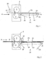
- in schematischer Seitenansicht ausschnittsweise einen eine lonisiervorrichtung aufweisenden Abschnitt einer papierverarbeitenden Maschine mit Anordnung der lonisiervorrichtung vor einem Querschneider;
- Fig. 2
- in schematischer Seitenansicht ausschnittsweise einen eine lonisiervorrichtung aufweisenden Abschnitt einer papierverarbeitenden Maschine, welche sich von
Figur 1 lediglich in der Anordnung der lonisiervorrichtung hinter dem Querschneider unterscheidet; - Fig. 3
- eine Draufsicht auf den Abschnitt einer papierverarbeitenden Maschine von
Figur 1 bzw.Figur 2 - Fig. 4
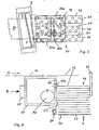
- schematisch im Querschnitt ausschnittsweise einen eine Entionisiereinrichtung aufweisenden weiteren Abschnitt einer papierverarbeitenden Maschine gemäß einer bevorzugten Ausführung der Erfindung.
- Fig. 1
- a schematic side view of a section of an ionizing device having portion of a paper processing machine with arrangement of the ionizing before a cross cutter;
- Fig. 2
- a schematic side view of a section of an ionizing device having a section of a paper-processing machine, which differs from
FIG. 1 only differs in the arrangement of the ionizing behind the cross cutter; - Fig. 3
- a plan view of the section of a paper processing machine of
FIG. 1 respectively.FIG. 2 omitting the ionizing device; and - Fig. 4
- schematically in cross-section detail a Entionisiereinrichtung having another section of a paper processing machine according to a preferred embodiment of the invention.
Ein erster Abschnitt einer papierverarbeitenden Maschine mit einem Querschneider 2 ist ausschnittsweise in dem
Zum Transport der mehrlagigen Papiermaterialbahn 10 in Richtung des Pfeils A ist stromaufwärts des Querschneiders 2 eine erste Fördervorrichtung vorgesehen, die in den Figuren nicht dargestellt ist. Ferner ist hinter dem Querschneider 2 stromabwärts eine zweite Fördervorrichtung 20 angeordnet, die mindestens ein über Umlenkwalzen 22, 24 endlos umlaufendes Unterband 26 aufweist, das mit seinem oberen Trum 26a in Richtung des Pfeils A läuft. Gewöhnlich sind mehrere Unterbänder 26 quer zur Laufrichtung der Bögen 12 gemäß Pfeil A nebeneinander angeordnet.For transporting the
Gemäß
Demgegenüber ist nach
Hinter dem Querschneider 2 werden die abgetrennten Bögen 12 auf oberen Trums 26a der Unterbänder 26 der zweiten Fördervorrichtung 20 transportiert, wobei die einzelnen Bögen 12 wegen der elektrostatischen Aufladung nicht aufblättern können. Zur Erhöhung der Reibung zwischen den Bögen 12 und dem oberen Trum 26a der Unterbänder 26 sind Saugkästen 40 vorgesehen, deren Oberseite eine Saugfläche 42 bildet, über die jeweils ein oberer Trum 26a der Oberbänder 26 läuft. Die Saugkästen 40 sind an eine nicht dargestellte Saugpumpe angeschlossen. Die Saugflächen 42, die den oberen Trum 26a der Unterbänder 26 tragen, sind perforiert, wie
Im übrigen ist es denkbar, die Saugflächen 42 und gegebenenfalls die Saugkästen 40 in Papierlaufrichtung gemäß Pfeil A nicht, wie in den
Aufgrund der zuvor beschriebenen Anordnung kann in der zweiten Fördervorrichtung 20, die die Bögen 12 zu einer nachfolgenden und in den Zeichnungen nicht dargestellten Überlappungsstation transportiert, auf die bisher üblichen Oberbänder verzichtet werden. Deshalb weist die zweite Fördervorrichtung 20 keine Oberbänder auf, wodurch die von der zweiten Fördervorrichtung 20 gebildete Förderstrecke konstruktiv vereinfacht und operativ zugänglicher wird.Due to the arrangement described above, in the second conveying
In
Papierverarbeitende Maschinen, die bahnförmige Materialien von einer oder mehreren Rollen abziehen und zu Formatmaterial verarbeiten, sind in der Mehrzahl der Fälle so konstruiert, dass innerhalb der Maschine ein schuppenförmig überlappter Strom von Bögen 12 erzeugt wird. Diese Schuppenform ist notwendig, um von der hohen Bahnabzugs- und Transportgeschwindigkeit, die aus Gründen der Produktivität der Anlage in dem in den
Sofern nicht eine gezielte elektrostatische Aufladung stattfindet, wie zuvor anhand der
Hierzu ist ein allseitig geschlossenes Gehäuse 60 vorgesehen, das aus einem nichtleitenden Material besteht. Das Gehäuse 60 weist einen Druckluftanschluß 62 auf, der an eine nicht dargestellte Druckluftquelle angeschlossen ist und durch den Druckluft in Richtung des Pfeils B in das Gehäuse 60 gepumpt wird. Mit seiner einen Seite 64 begrenzt das Gehäuse 60 die Stapelablage 50. Diese der Stapelablage 50 zugewandte Seite 64 des Gehäuses 60 bildet im dargestellten Ausführungsbeispiel eine vertikale ebene Fläche, an die der Stapel 14 in Anlage bringbar ist. Somit übernimmt im dargestellten Ausführungsbeispiel die Seite 64 des Gehäuses 60 die Funktion des hinteren Stapelanschlages und übernimmt auch gleichzeitig die Anrichtfunktion. Somit kann diese vertikale Seite 64 des Gehäuses 60 auch als hinterer Anrichter bezeichnet werden.For this purpose, an all-sided
In Förderrichtung wird die Stapelablage 50 durch einen Frontanrichter 68 begrenzt, der als Anschlag für die zur Stapelablage 50 geförderten Bögen 12 dient und im wesentlichen aus einem vertikal angeordneten Plattenkörper besteht. Demnach sind die der Stapelablage 50 zugewandete Seite 64 des Gehäuses 60 und der Frontanrichter 68 Teile eines Anrichtmechanismus bzw. bilden den Anrichtmechanismus.In the conveying direction, the
Ferner sind in der der Stapelablage 50 zugewandeten Seite 64 des Gehäuses 60 mehrere düsenförmige Luftaustrittsöffnungen 66 ausgebildet, und zwar dergestalt, dass sie über die gesamte Arbeitsbreite in regelmäßigen Abständen senkrecht verlaufende Bohrbilder bilden. Diese Öffnungen 66 sind derart gestaltet, dass sie einen beschleunigten Austritt der durch den Druckluftanschluß 62 eintretenden Druckluft in Richtung auf den sich bildenden Stapel erzielen. Die dabei entstehenden Luftströme treten im Wesentlichen in Längsrichtung der den Stapel 14 bildenden Bögen 12 aus und sind auf deren hintere Ränder 12a gerichtet. Auf diese Weise entstehen in der Stapelablage 50 zwischen den absinkenden Bögen 12 Luftpolster, die in Verbindung mit dem bereits erwähnten, jedoch nicht dargestellten Anrichtmechanismus für eine exakte Kantenbildung des entstehenden Stapels 14 sorgen. Denn für die Bildung des Stapels 14 ist es notwendig, dass den Bögen 12, die in schuppenförmig überlappender Anordnung gegen den Frontanrichter 68 einlaufen, sowohl eine gute Relativverschiebung untereinander als auch das Schweben auf einem Luftpolster beim Absinken auf die Oberfläche des sich bildenden Stapels 14 ermöglicht wird.Further, in the
Zur elektrostatischen Entladung der Bögen 12 ist im dargestellten Ausführungsbeispiel innerhalb des Gehäuses 60 eine Entionisiereinrichtung 70 angeordnet, die vorzugsweise aus einem Antistatikstab besteht. Diese Entionisiereinrichtung 70 ionisiert die durch den Druckluftanschluß 62 in das Gehäuse 60 eintretende Druckluft mit gegenüber den Bögen 12 entgegengesetzter Polarität, so dass die aus den Austrittsöffnungen 66 austretende Druckluft gleichzeitig eine entionisierende Wirkung auf die Bögen 12 des sich bildenden Stapels 14 ausübt. Somit wird durch das gezielte Einbringen von Blasluft mit entionisierender Wirkung in den sich bildenden Stapel 14 sowohl eine elektrostatische Neutralisierung der Bögen 12 als auch die Erzeugung des zuvor beschriebenen Luftpolsters genau an dem Ort sichergestellt, an dem diese Wirkungen unbedingt vorhanden sein müssen.For the electrostatic discharge of the
Dabei muß unter allen Umständen darauf geachtet werden, dass das Gehäuse 60 keine elektrisch leitenden Verbindungen erhält. Auch auf der Seite des Luftaustrittes, also außerhalb des Gehäuses 60 im Bereich der Austrittsöffnungen 66, ist unbedingt darauf zu achten, dass die austretende entionisierende Luft im Bereich der Austrittsöffnung 66 und im weiteren Verlauf der Blasrichtung keinesfalls mit elektrisch leitenden Bauteilen in Berührung kommt, da sie sonst sofort neutralisiert würde.It must be ensured under all circumstances that the
Die Stapelablage 50 wird nach unten durch einen Boden 52 begrenzt, auf dem Bögen 12 zur Bildung des Stapels 14 aufgeschichtet werden und der durch eine nicht dargestellte Mechanik in vertikaler Richtung gemäß Doppelpfeil C bewegbar gelagert ist. Während der Bildung des Stapels 14 muß dabei die Absenkbewegung des Bodens 52 so gesteuert werden, dass sich der Stapel 14 mit dem jeweils obersten Bogen 12 und somit seiner dadurch entstehenden Oberseite stets auf der Höhe der Austrittsöffnungen 66 und insbesondere zwischen den oberen und unteren Austrittsöffnungen 66 befindet, um eine funktionsgerechte Ausbildung des Luftpolsters durch die aus den Austrittsöffnungen 66 austretende entionisierende Druckluft zu erzielen.The
Wie schließlich
Claims (17)
- Device for processing a multi-layer electrostatically chargeable material strip into individual superimposed sheets (12), with a conveying device for transporting the sheets (12), an electrostatic discharging device for the electrostatic discharging of the sheets (12) and a stacking unit (50) located downstream of the conveying device for forming stacks (14) of the superimposed sheets (12), wherein the electrostatic discharging device is arranged in the region of the stacking unit (50) and comprises a device (70) for the electrostatic charging of compressed air with a polarity opposite to that of the sheets (12), and a blowing device (66) for blowing this air against the sheets (12), characterised in that the device (70) for the electrostatic charging of the compressed air and the blowing device (66) are located in a housing (60), a section (64) of which delimits the stacking unit (50), forms a stop means for the stacks (14) and comprises the blowing device (66).
- Device according to claim 1, characterised in that the electrostatic discharging device is arranged in the upstream section, preferably on the upstream side, of the stacking unit (50).
- Device according to claim 1 or 2, characterised in that the electrostatic discharging device comprises an air compression device for producing compressed air.
- Device according to at least one of the preceding claims, characterised in that the blowing device blows the air substantially against the passing edges (12a) of the sheets (12).
- Device according to at least one of the preceding claims, characterised in that the blowing device comprises a nozzle arrangement (66).
- Device according to claim 5, characterised in that the section (64) of the housing (60) delimiting the stacking unit (50) is provided with openings (66) for blowing out the air.
- Device according to at least one of the preceding claims, characterised in that the electrostatic discharging device is a deionising device for deionising the sheets.
- Device according to at least one of the preceding claims, characterised by suction means (80) in the lower section of the stacking unit (50).
- Device according to at least one of the preceding claims, characterised by at least one cutting device (2) for cutting the multi-layer material strip (10) into corresponding superimposed sheets (12), an electrostatic charging device (30) for the electrostatic charging of the multi-layer material strip (10) and a first conveying device (20) located upstream of the cutting device (2) and a second conveying device (20) located downstream behind the cutting device (2), for transporting the multi-layer material strip (10, 12), wherein the electrostatic charging device (30) is arranged in the region of the first or second conveying device (20) adjacent to the cutting device (2).
- Device according to claim 9, characterised in that the electrostatic charging device (30) is arranged substantially between the cutting device (2) and the first or second conveying device (20).
- Device according to claim 9 or 10, characterised in that the second conveying device (20) comprises an endless conveyer belt arrangement (26), wherein the endless conveyer belt arrangement consists simply of one or more lower belts (26), on which the multi-layer material strip (12) rests.
- Device according to at least one of claims 9 to 11, characterised in that the second conveying device (20) comprises a suction device (40).
- Device according to claims 11 and 12, characterised in that an upper strand (26a) of the conveyer belt arrangement (26) runs above the suction device (40).
- Device according to claim 13, characterised in that the suction device (40) comprises a suction surface (42), wherein an upper strand (26a) of the conveyer belt arrangement (26) rests on the suction surface (42).
- Device according to claim 13 or 14, characterised in that at least one lower belt (26) is perforated.
- Device according to at least one of claims 9 to 15, characterised in that the electrostatic charging device (30) is an ionising device for ionising the multi-layer material strip (10).
- Device according to at least one of claims 9 to 16, characterised in that the cutting device (2) comprises a crosswise cutter.
Applications Claiming Priority (3)
| Application Number | Priority Date | Filing Date | Title |
|---|---|---|---|
| DE10344192 | 2003-09-22 | ||
| DE10344192A DE10344192B4 (en) | 2003-09-22 | 2003-09-22 | Apparatus for processing stacks of electrostatically chargeable flat parts |
| EP04022117A EP1516838B1 (en) | 2003-09-22 | 2004-09-17 | Device for processing stacks of electrostatic rechargeable flat parts |
Related Parent Applications (1)
| Application Number | Title | Priority Date | Filing Date |
|---|---|---|---|
| EP04022117A Division EP1516838B1 (en) | 2003-09-22 | 2004-09-17 | Device for processing stacks of electrostatic rechargeable flat parts |
Publications (2)
| Publication Number | Publication Date |
|---|---|
| EP1595836A1 EP1595836A1 (en) | 2005-11-16 |
| EP1595836B1 true EP1595836B1 (en) | 2009-01-14 |
Family
ID=34177918
Family Applications (2)
| Application Number | Title | Priority Date | Filing Date |
|---|---|---|---|
| EP04022117A Active EP1516838B1 (en) | 2003-09-22 | 2004-09-17 | Device for processing stacks of electrostatic rechargeable flat parts |
| EP05015721A Active EP1595836B1 (en) | 2003-09-22 | 2004-09-17 | Device for processing stacks of electrostatic rechargeable flat parts |
Family Applications Before (1)
| Application Number | Title | Priority Date | Filing Date |
|---|---|---|---|
| EP04022117A Active EP1516838B1 (en) | 2003-09-22 | 2004-09-17 | Device for processing stacks of electrostatic rechargeable flat parts |
Country Status (14)
| Country | Link |
|---|---|
| US (1) | US20050077171A1 (en) |
| EP (2) | EP1516838B1 (en) |
| JP (1) | JP2005096997A (en) |
| KR (1) | KR100704459B1 (en) |
| CN (1) | CN1673057B (en) |
| AT (2) | ATE398595T1 (en) |
| AU (1) | AU2004212613A1 (en) |
| BR (1) | BRPI0404018A (en) |
| CA (1) | CA2482167A1 (en) |
| DE (3) | DE10344192B4 (en) |
| ES (2) | ES2306945T3 (en) |
| PT (2) | PT1595836E (en) |
| RU (1) | RU2364566C2 (en) |
| ZA (1) | ZA200407562B (en) |
Families Citing this family (22)
| Publication number | Priority date | Publication date | Assignee | Title |
|---|---|---|---|---|
| DE10344192B4 (en) * | 2003-09-22 | 2009-04-30 | E.C.H. Will Gmbh | Apparatus for processing stacks of electrostatically chargeable flat parts |
| NL1029461C2 (en) * | 2005-07-07 | 2007-01-09 | Simco Nederland | Method and device for holding together an electrically non-conductive stack of objects. |
| DE102006009785A1 (en) * | 2006-03-01 | 2007-09-06 | E.C.H. Will Gmbh | Apparatus, method and apparatus for collecting flat parts into stacks |
| DE102007024945A1 (en) * | 2006-06-06 | 2007-12-13 | Eastman Kodak Co. | Sheet transporting method for use in e.g. inkjet printer, involves applying electrical charges in area within which sheet is sucked into rotating conveyor for generating electrostatic retention force between rotating conveyor and sheet |
| JP2008264967A (en) * | 2007-04-24 | 2008-11-06 | Komori Corp | Sheeter device |
| US8559156B2 (en) | 2008-06-03 | 2013-10-15 | Illinois Tool Works Inc. | Method and apparatus for charging or neutralizing an object using a charged piece of conductive plastic |
| KR100929191B1 (en) * | 2009-03-11 | 2009-12-01 | 태평판지 주식회사 | Paper feeding device |
| DE102012206847A1 (en) * | 2012-04-25 | 2013-11-07 | E.C.H. Will Gmbh | Suction conveyor for transporting flat parts |
| WO2015067273A1 (en) * | 2013-11-06 | 2015-05-14 | Jesco Holding Aps | A system and a method for providing ionised air to extrusion blow molded web materials, and a cutter for cutting a tube shaped extrusion blow molded web into two or more webs |
| SE538854C2 (en) | 2014-01-09 | 2017-01-03 | Valmet Oy | Wheelchair for receiving and rolling up a paper web, which comes from a drying cylinder in a paper machine, to a roll, as well as a paper machine using a wheelchair |
| WO2015189801A1 (en) * | 2014-06-13 | 2015-12-17 | Bierrebi Italia S.R.L. | Apparatus for processing, in particular for cutting a corresponding material |
| JP6529305B2 (en) * | 2015-03-26 | 2019-06-12 | 株式会社小森コーポレーション | Sheet discharge device |
| CN106185438A (en) * | 2016-08-24 | 2016-12-07 | 成都瀚江新材科技股份有限公司 | A kind of filling machine automatically |
| AT520462A1 (en) * | 2017-09-15 | 2019-04-15 | Andritz Ag Maschf | Method for cross-cutting a material web moved along a direction of movement, and device for this purpose |
| JP7386605B2 (en) * | 2017-11-30 | 2023-11-27 | ミュラー・マルティニ・ホルディング・アクチエンゲゼルシヤフト | Apparatus and method for cutting or perforating paper webs |
| CN108214611A (en) * | 2018-01-29 | 2018-06-29 | 启东市美迅机械有限公司 | A kind of transverse cutting mechanism |
| CN108622667A (en) * | 2018-04-16 | 2018-10-09 | 泉州市科盛包装机械有限公司 | A kind of cigarette stablizes clamp method |
| CN112041175B (en) * | 2018-07-23 | 2022-06-03 | 惠普发展公司,有限责任合伙企业 | Media transport |
| CN109434932A (en) * | 2018-09-30 | 2019-03-08 | 上海诗冠印刷有限公司 | A kind of material collecting device of die-cutting machine |
| CN113799478B (en) * | 2020-06-17 | 2023-09-12 | 菱铁(厦门)机械有限公司 | Film printing system |
| CN112141769B (en) * | 2020-10-24 | 2022-03-25 | 潍坊合一机械有限公司 | Shoe-shaped gold ingot machine and paper folding process |
| US20230034891A1 (en) * | 2021-07-28 | 2023-02-02 | Inteplast Group Corporation | Sheet product package and method of making dispensable sheet product |
Family Cites Families (17)
| Publication number | Priority date | Publication date | Assignee | Title |
|---|---|---|---|---|
| DE1245702B (en) * | 1961-06-02 | 1967-07-27 | Jagenberg Werke Ag | Device for conveying, overlapping and depositing sheets of paper or the like. |
| DE2100980C3 (en) * | 1971-01-11 | 1973-11-29 | Clark-Aiken International, Inc., Lee, Mass. (V.St.A.) | Conveyor device for a continuous stream of sheets |
| US3892614A (en) * | 1973-03-08 | 1975-07-01 | Simco Co Inc | Electrostatic laminating apparatus and method |
| CA1176277A (en) * | 1980-01-21 | 1984-10-16 | Donald C. Fitzpatrick | Telescoping air jets for piling |
| DE3508514A1 (en) * | 1985-03-09 | 1986-09-11 | E.C.H. Will (Gmbh & Co), 2000 Hamburg | Method and device for stabilising stacks of paper |
| JPH0687178B2 (en) * | 1988-07-01 | 1994-11-02 | バンドー化学株式会社 | Dielectric sheet conveyor |
| US5263697A (en) * | 1989-04-18 | 1993-11-23 | Ricoh Company, Ltd. | Finisher for an image forming apparatus |
| US5062764A (en) * | 1990-01-08 | 1991-11-05 | Robert A. Foisie | Method and apparatus using electrostatic charges to stabilize the upper sheets of a stack of paper |
| US5064180A (en) * | 1990-04-09 | 1991-11-12 | Harris Graphics Corporation | Electrostatic diverter |
| JP3856170B2 (en) * | 1996-11-18 | 2006-12-13 | 富士フイルムホールディングス株式会社 | Web adsorbing force control method and apparatus |
| US6073527A (en) * | 1997-04-11 | 2000-06-13 | Marquip, Inc. | Method and apparatus for direct shingling of cut sheets at the cutoff knife |
| US6309400B2 (en) * | 1998-06-29 | 2001-10-30 | Ethicon Endo-Surgery, Inc. | Curved ultrasonic blade having a trapezoidal cross section |
| DE10043211A1 (en) * | 2000-09-01 | 2002-03-14 | Heidelberger Druckmasch Ag | Electrostatic charge applicator, used for multi-layer strip passing through printing machine, comprises roller surfaces and cutters electrically insulated |
| DE10128653A1 (en) * | 2001-06-15 | 2002-12-19 | Will E C H Gmbh & Co | Conveyor for sheet layers and method for bringing sheet layers together |
| DE10144287A1 (en) * | 2001-09-08 | 2003-04-03 | Lohmann Therapie Syst Lts | Method for the electrostatic fixing of sheet-like objects on a base |
| DE10146919C1 (en) * | 2001-09-24 | 2003-05-15 | Koenig & Bauer Ag | Device for aligning sheets arranged one above the other in a layer |
| DE10344192B4 (en) * | 2003-09-22 | 2009-04-30 | E.C.H. Will Gmbh | Apparatus for processing stacks of electrostatically chargeable flat parts |
-
2003
- 2003-09-22 DE DE10344192A patent/DE10344192B4/en not_active Expired - Lifetime
-
2004
- 2004-09-17 PT PT05015721T patent/PT1595836E/en unknown
- 2004-09-17 ES ES04022117T patent/ES2306945T3/en active Active
- 2004-09-17 EP EP04022117A patent/EP1516838B1/en active Active
- 2004-09-17 PT PT04022117T patent/PT1516838E/en unknown
- 2004-09-17 ES ES05015721T patent/ES2318386T3/en active Active
- 2004-09-17 DE DE502004007379T patent/DE502004007379D1/en active Active
- 2004-09-17 AT AT04022117T patent/ATE398595T1/en active
- 2004-09-17 AT AT05015721T patent/ATE420835T1/en active
- 2004-09-17 EP EP05015721A patent/EP1595836B1/en active Active
- 2004-09-17 DE DE502004008868T patent/DE502004008868D1/en active Active
- 2004-09-20 CA CA002482167A patent/CA2482167A1/en not_active Abandoned
- 2004-09-21 AU AU2004212613A patent/AU2004212613A1/en not_active Abandoned
- 2004-09-21 ZA ZA200407562A patent/ZA200407562B/en unknown
- 2004-09-21 JP JP2004272723A patent/JP2005096997A/en active Pending
- 2004-09-22 KR KR1020040075750A patent/KR100704459B1/en active IP Right Grant
- 2004-09-22 US US10/946,617 patent/US20050077171A1/en not_active Abandoned
- 2004-09-22 BR BR0404018-0A patent/BRPI0404018A/en not_active IP Right Cessation
- 2004-09-22 RU RU2004128325/11A patent/RU2364566C2/en not_active IP Right Cessation
- 2004-09-22 CN CN2004101037692A patent/CN1673057B/en active Active
Also Published As
| Publication number | Publication date |
|---|---|
| ES2306945T3 (en) | 2008-11-16 |
| RU2004128325A (en) | 2006-03-10 |
| PT1516838E (en) | 2008-09-26 |
| JP2005096997A (en) | 2005-04-14 |
| US20050077171A1 (en) | 2005-04-14 |
| AU2004212613A1 (en) | 2005-04-07 |
| RU2364566C2 (en) | 2009-08-20 |
| ZA200407562B (en) | 2005-07-01 |
| DE10344192B4 (en) | 2009-04-30 |
| EP1516838A2 (en) | 2005-03-23 |
| CN1673057B (en) | 2010-11-24 |
| KR100704459B1 (en) | 2007-04-10 |
| ATE420835T1 (en) | 2009-01-15 |
| CN1673057A (en) | 2005-09-28 |
| CA2482167A1 (en) | 2005-03-22 |
| ATE398595T1 (en) | 2008-07-15 |
| EP1516838B1 (en) | 2008-06-18 |
| BRPI0404018A (en) | 2005-05-24 |
| DE502004008868D1 (en) | 2009-03-05 |
| DE502004007379D1 (en) | 2008-07-31 |
| EP1516838A3 (en) | 2005-06-01 |
| EP1595836A1 (en) | 2005-11-16 |
| ES2318386T3 (en) | 2009-05-01 |
| DE10344192A1 (en) | 2005-05-04 |
| PT1595836E (en) | 2009-03-10 |
| KR20050029715A (en) | 2005-03-28 |
| EP1516838A9 (en) | 2005-07-27 |
Similar Documents
| Publication | Publication Date | Title |
|---|---|---|
| EP1595836B1 (en) | Device for processing stacks of electrostatic rechargeable flat parts | |
| EP0986478B1 (en) | Method for threading a partial paper web | |
| EP0108109B1 (en) | Device for separating layers of continuous forms or the like | |
| EP0559846B1 (en) | Device for turning a sheet with a simultaneous change in the direction of transport | |
| DE2643709A1 (en) | SORTING DEVICE FOR UNORDERLY DISTRIBUTED PARTS | |
| EP1266854B9 (en) | Transport device for sheets and method for assembling sheets | |
| DE4314832C1 (en) | Stacking device for tabular goods | |
| EP2841367B1 (en) | Apparatus for imbricating sheets and depositing them on a stack | |
| DE3805779A1 (en) | DEVICE AND METHOD FOR SHINGLING INDIVIDUAL SHEETS PROVIDED FROM CURRENT TO CURRENT | |
| EP0567807A1 (en) | Active work station for a stream of printed products in shingled formation | |
| DE4034339C2 (en) | Method and device for electrostatically charging sheets of paper | |
| EP1037829B1 (en) | Device for transferring two-dimensional products onto a transportation device | |
| EP0697989B1 (en) | Device for stream feeding of sheets onto a stack | |
| EP2841365A1 (en) | Suction conveyor device for transporting flat items, and system for producing flat items comprising said type of suction conveyor | |
| EP0890538B1 (en) | Slitter | |
| EP0820949A1 (en) | Sheet guidance device at the cutting cylinders of a folding machine | |
| DE1931208C3 (en) | Device for conveying and depositing sheets of paper and other sheet material in stacks | |
| DE60113810T2 (en) | DEVICE FOR SEPARATING WASTE IN THE CUTTING OF PAPER ROLLS FROM A LONG ROD | |
| DE4012943C2 (en) | ||
| DE102008025667A1 (en) | Conveyor for sheet layers and method for forming and conveying a scale flow from sheet layers | |
| EP1612174B1 (en) | Device for aligning a stack of sheets arranged one above the other | |
| DE60312521T2 (en) | Machine for applying partially adhesive strips to products | |
| DE2100980A1 (en) | Device for cutting and conveying sheets of paper | |
| WO2013160402A1 (en) | Removal device for removing flat items | |
| EP1829806B1 (en) | Device, method and installation for gathering superposed sheets in stacks |
Legal Events
| Date | Code | Title | Description |
|---|---|---|---|
| PUAI | Public reference made under article 153(3) epc to a published international application that has entered the european phase |
Free format text: ORIGINAL CODE: 0009012 |
|
| AC | Divisional application: reference to earlier application |
Ref document number: 1516838 Country of ref document: EP Kind code of ref document: P |
|
| AK | Designated contracting states |
Kind code of ref document: A1 Designated state(s): AT BE BG CH CY CZ DE DK EE ES FI FR GB GR HU IE IT LI LU MC NL PL PT RO SE SI SK TR |
|
| AX | Request for extension of the european patent |
Extension state: AL HR LT LV MK |
|
| 17P | Request for examination filed |
Effective date: 20060324 |
|
| AKX | Designation fees paid |
Designated state(s): AT BE BG CH CY CZ DE DK EE ES FI FR GB GR HU IE IT LI LU MC NL PL PT RO SE SI SK TR |
|
| GRAP | Despatch of communication of intention to grant a patent |
Free format text: ORIGINAL CODE: EPIDOSNIGR1 |
|
| GRAC | Information related to communication of intention to grant a patent modified |
Free format text: ORIGINAL CODE: EPIDOSCIGR1 |
|
| GRAS | Grant fee paid |
Free format text: ORIGINAL CODE: EPIDOSNIGR3 |
|
| GRAA | (expected) grant |
Free format text: ORIGINAL CODE: 0009210 |
|
| AC | Divisional application: reference to earlier application |
Ref document number: 1516838 Country of ref document: EP Kind code of ref document: P |
|
| AK | Designated contracting states |
Kind code of ref document: B1 Designated state(s): AT BE BG CH CY CZ DE DK EE ES FI FR GB GR HU IE IT LI LU MC NL PL PT RO SE SI SK TR |
|
| REG | Reference to a national code |
Ref country code: GB Ref legal event code: FG4D Free format text: NOT ENGLISH |
|
| REG | Reference to a national code |
Ref country code: CH Ref legal event code: EP |
|
| REG | Reference to a national code |
Ref country code: IE Ref legal event code: FG4D Free format text: LANGUAGE OF EP DOCUMENT: GERMAN |
|
| REF | Corresponds to: |
Ref document number: 502004008868 Country of ref document: DE Date of ref document: 20090305 Kind code of ref document: P |
|
| REG | Reference to a national code |
Ref country code: PT Ref legal event code: SC4A Free format text: AVAILABILITY OF NATIONAL TRANSLATION Effective date: 20090226 |
|
| REG | Reference to a national code |
Ref country code: SE Ref legal event code: TRGR |
|
| REG | Reference to a national code |
Ref country code: ES Ref legal event code: FG2A Ref document number: 2318386 Country of ref document: ES Kind code of ref document: T3 |
|
| PG25 | Lapsed in a contracting state [announced via postgrant information from national office to epo] |
Ref country code: SI Free format text: LAPSE BECAUSE OF FAILURE TO SUBMIT A TRANSLATION OF THE DESCRIPTION OR TO PAY THE FEE WITHIN THE PRESCRIBED TIME-LIMIT Effective date: 20090114 |
|
| REG | Reference to a national code |
Ref country code: IE Ref legal event code: FD4D |
|
| PG25 | Lapsed in a contracting state [announced via postgrant information from national office to epo] |
Ref country code: PL Free format text: LAPSE BECAUSE OF FAILURE TO SUBMIT A TRANSLATION OF THE DESCRIPTION OR TO PAY THE FEE WITHIN THE PRESCRIBED TIME-LIMIT Effective date: 20090114 |
|
| PG25 | Lapsed in a contracting state [announced via postgrant information from national office to epo] |
Ref country code: DK Free format text: LAPSE BECAUSE OF FAILURE TO SUBMIT A TRANSLATION OF THE DESCRIPTION OR TO PAY THE FEE WITHIN THE PRESCRIBED TIME-LIMIT Effective date: 20090114 Ref country code: EE Free format text: LAPSE BECAUSE OF FAILURE TO SUBMIT A TRANSLATION OF THE DESCRIPTION OR TO PAY THE FEE WITHIN THE PRESCRIBED TIME-LIMIT Effective date: 20090114 Ref country code: CZ Free format text: LAPSE BECAUSE OF FAILURE TO SUBMIT A TRANSLATION OF THE DESCRIPTION OR TO PAY THE FEE WITHIN THE PRESCRIBED TIME-LIMIT Effective date: 20090114 Ref country code: IE Free format text: LAPSE BECAUSE OF FAILURE TO SUBMIT A TRANSLATION OF THE DESCRIPTION OR TO PAY THE FEE WITHIN THE PRESCRIBED TIME-LIMIT Effective date: 20090114 |
|
| PLBE | No opposition filed within time limit |
Free format text: ORIGINAL CODE: 0009261 |
|
| STAA | Information on the status of an ep patent application or granted ep patent |
Free format text: STATUS: NO OPPOSITION FILED WITHIN TIME LIMIT |
|
| PG25 | Lapsed in a contracting state [announced via postgrant information from national office to epo] |
Ref country code: SK Free format text: LAPSE BECAUSE OF FAILURE TO SUBMIT A TRANSLATION OF THE DESCRIPTION OR TO PAY THE FEE WITHIN THE PRESCRIBED TIME-LIMIT Effective date: 20090114 Ref country code: RO Free format text: LAPSE BECAUSE OF FAILURE TO SUBMIT A TRANSLATION OF THE DESCRIPTION OR TO PAY THE FEE WITHIN THE PRESCRIBED TIME-LIMIT Effective date: 20090114 |
|
| PGFP | Annual fee paid to national office [announced via postgrant information from national office to epo] |
Ref country code: NL Payment date: 20090923 Year of fee payment: 6 |
|
| 26N | No opposition filed |
Effective date: 20091015 |
|
| PG25 | Lapsed in a contracting state [announced via postgrant information from national office to epo] |
Ref country code: BG Free format text: LAPSE BECAUSE OF FAILURE TO SUBMIT A TRANSLATION OF THE DESCRIPTION OR TO PAY THE FEE WITHIN THE PRESCRIBED TIME-LIMIT Effective date: 20090414 |
|
| PG25 | Lapsed in a contracting state [announced via postgrant information from national office to epo] |
Ref country code: MC Free format text: LAPSE BECAUSE OF NON-PAYMENT OF DUE FEES Effective date: 20090930 |
|
| REG | Reference to a national code |
Ref country code: CH Ref legal event code: PL |
|
| PG25 | Lapsed in a contracting state [announced via postgrant information from national office to epo] |
Ref country code: LI Free format text: LAPSE BECAUSE OF NON-PAYMENT OF DUE FEES Effective date: 20090930 Ref country code: CH Free format text: LAPSE BECAUSE OF NON-PAYMENT OF DUE FEES Effective date: 20090930 Ref country code: GR Free format text: LAPSE BECAUSE OF FAILURE TO SUBMIT A TRANSLATION OF THE DESCRIPTION OR TO PAY THE FEE WITHIN THE PRESCRIBED TIME-LIMIT Effective date: 20090415 |
|
| PGFP | Annual fee paid to national office [announced via postgrant information from national office to epo] |
Ref country code: AT Payment date: 20100928 Year of fee payment: 7 Ref country code: FI Payment date: 20100928 Year of fee payment: 7 Ref country code: FR Payment date: 20101005 Year of fee payment: 7 Ref country code: SE Payment date: 20100923 Year of fee payment: 7 |
|
| PGFP | Annual fee paid to national office [announced via postgrant information from national office to epo] |
Ref country code: GB Payment date: 20100929 Year of fee payment: 7 |
|
| PGFP | Annual fee paid to national office [announced via postgrant information from national office to epo] |
Ref country code: PT Payment date: 20100818 Year of fee payment: 7 |
|
| PGFP | Annual fee paid to national office [announced via postgrant information from national office to epo] |
Ref country code: BE Payment date: 20100929 Year of fee payment: 7 |
|
| REG | Reference to a national code |
Ref country code: NL Ref legal event code: V1 Effective date: 20110401 |
|
| PG25 | Lapsed in a contracting state [announced via postgrant information from national office to epo] |
Ref country code: LU Free format text: LAPSE BECAUSE OF NON-PAYMENT OF DUE FEES Effective date: 20090917 |
|
| PG25 | Lapsed in a contracting state [announced via postgrant information from national office to epo] |
Ref country code: HU Free format text: LAPSE BECAUSE OF FAILURE TO SUBMIT A TRANSLATION OF THE DESCRIPTION OR TO PAY THE FEE WITHIN THE PRESCRIBED TIME-LIMIT Effective date: 20090715 |
|
| PG25 | Lapsed in a contracting state [announced via postgrant information from national office to epo] |
Ref country code: TR Free format text: LAPSE BECAUSE OF FAILURE TO SUBMIT A TRANSLATION OF THE DESCRIPTION OR TO PAY THE FEE WITHIN THE PRESCRIBED TIME-LIMIT Effective date: 20090114 Ref country code: NL Free format text: LAPSE BECAUSE OF NON-PAYMENT OF DUE FEES Effective date: 20110401 |
|
| PG25 | Lapsed in a contracting state [announced via postgrant information from national office to epo] |
Ref country code: CY Free format text: LAPSE BECAUSE OF FAILURE TO SUBMIT A TRANSLATION OF THE DESCRIPTION OR TO PAY THE FEE WITHIN THE PRESCRIBED TIME-LIMIT Effective date: 20090114 |
|
| REG | Reference to a national code |
Ref country code: PT Ref legal event code: MM4A Free format text: LAPSE DUE TO NON-PAYMENT OF FEES Effective date: 20120319 |
|
| BERE | Be: lapsed |
Owner name: E.C.H. WILL G.M.B.H. Effective date: 20110930 |
|
| GBPC | Gb: european patent ceased through non-payment of renewal fee |
Effective date: 20110917 |
|
| PG25 | Lapsed in a contracting state [announced via postgrant information from national office to epo] |
Ref country code: PT Free format text: LAPSE BECAUSE OF NON-PAYMENT OF DUE FEES Effective date: 20120319 Ref country code: FI Free format text: LAPSE BECAUSE OF NON-PAYMENT OF DUE FEES Effective date: 20110917 |
|
| REG | Reference to a national code |
Ref country code: FR Ref legal event code: ST Effective date: 20120531 |
|
| PG25 | Lapsed in a contracting state [announced via postgrant information from national office to epo] |
Ref country code: BE Free format text: LAPSE BECAUSE OF NON-PAYMENT OF DUE FEES Effective date: 20110930 |
|
| REG | Reference to a national code |
Ref country code: SE Ref legal event code: EUG |
|
| PG25 | Lapsed in a contracting state [announced via postgrant information from national office to epo] |
Ref country code: FR Free format text: LAPSE BECAUSE OF NON-PAYMENT OF DUE FEES Effective date: 20110930 Ref country code: GB Free format text: LAPSE BECAUSE OF NON-PAYMENT OF DUE FEES Effective date: 20110917 |
|
| REG | Reference to a national code |
Ref country code: AT Ref legal event code: MM01 Ref document number: 420835 Country of ref document: AT Kind code of ref document: T Effective date: 20110917 |
|
| PG25 | Lapsed in a contracting state [announced via postgrant information from national office to epo] |
Ref country code: AT Free format text: LAPSE BECAUSE OF NON-PAYMENT OF DUE FEES Effective date: 20110917 |
|
| PG25 | Lapsed in a contracting state [announced via postgrant information from national office to epo] |
Ref country code: SE Free format text: LAPSE BECAUSE OF NON-PAYMENT OF DUE FEES Effective date: 20110918 |
|
| REG | Reference to a national code |
Ref country code: DE Ref legal event code: R082 Ref document number: 502004008868 Country of ref document: DE Representative=s name: VON ROHR PATENTANWAELTE PARTNERSCHAFT MBB, DE Ref country code: DE Ref legal event code: R081 Ref document number: 502004008868 Country of ref document: DE Owner name: BW PAPERSYSTEMS HAMBURG GMBH, DE Free format text: FORMER OWNER: E.C.H. WILL GMBH, 22529 HAMBURG, DE |
|
| PGFP | Annual fee paid to national office [announced via postgrant information from national office to epo] |
Ref country code: DE Payment date: 20220629 Year of fee payment: 19 |
|
| PGFP | Annual fee paid to national office [announced via postgrant information from national office to epo] |
Ref country code: IT Payment date: 20220926 Year of fee payment: 19 Ref country code: ES Payment date: 20221121 Year of fee payment: 19 |