EP1595772B1 - Vehicle body floor structure - Google Patents
Vehicle body floor structure Download PDFInfo
- Publication number
- EP1595772B1 EP1595772B1 EP05252219A EP05252219A EP1595772B1 EP 1595772 B1 EP1595772 B1 EP 1595772B1 EP 05252219 A EP05252219 A EP 05252219A EP 05252219 A EP05252219 A EP 05252219A EP 1595772 B1 EP1595772 B1 EP 1595772B1
- Authority
- EP
- European Patent Office
- Prior art keywords
- vehicle body
- floor
- cross member
- reinforce
- cross
- Prior art date
- Legal status (The legal status is an assumption and is not a legal conclusion. Google has not performed a legal analysis and makes no representation as to the accuracy of the status listed.)
- Expired - Lifetime
Links
- 238000003780 insertion Methods 0.000 description 4
- 230000037431 insertion Effects 0.000 description 4
- 230000000694 effects Effects 0.000 description 2
- 239000012212 insulator Substances 0.000 description 2
- 239000000463 material Substances 0.000 description 2
- 238000010276 construction Methods 0.000 description 1
- 239000006185 dispersion Substances 0.000 description 1
- 238000012986 modification Methods 0.000 description 1
- 230000004048 modification Effects 0.000 description 1
- 230000003014 reinforcing effect Effects 0.000 description 1
Images


Classifications
-
- B—PERFORMING OPERATIONS; TRANSPORTING
- B62—LAND VEHICLES FOR TRAVELLING OTHERWISE THAN ON RAILS
- B62D—MOTOR VEHICLES; TRAILERS
- B62D24/00—Connections between vehicle body and vehicle frame
- B62D24/02—Vehicle body, not intended to move relatively to the vehicle frame, and mounted on vibration absorbing mountings, e.g. rubber pads
Definitions
- the present invention relates to a vehicle body floor structure and, more particularly, to a vehicle body floor structure around an assembled portion, between a front end of a side sill and an end of a dash panel in a vehicle-widthwise direction, of a vehicle body floor section of an automobile.
- Japanese Patent Application Laid-open Publication No. 2000-225966 discloses a vehicle body of an automobile with a structure wherein a reinforce member is joined to front ends of side sills, which form a fore and aft oriented frame member on both sides of a floor, to form a closed cross-sectional sections on front outside ends of the side sills (see Page 3 and FIG. 4 ).
- JP58-067569 discloses an under-floor cross member between front frame members, and a bracket between a front frame members and a side sill.
- the side sill To address such an issue, a need arises for the side sill to have an increased plate thickness or to be made of material with increased strength, causing factors to occur in increase in weight and cost.
- the present invention has been completed with the above study in mind conducted by the present inventor and has an object to provide a vehicle body floor structure, additionally provided with a partially formed reinforce, which is able to adequately withstand both a rearward colliding input, applied to a front end of the side sill, and a colliding input applied to the vehicle body in a vehicle-widthwise direction.
- a vehicle body floor structure comprising: a cross member connected to at least one of a pair of side sill inners, extending in a fore and aft direction of a vehicle body at both ends of the cross member in a widthwise direction of the vehicle body, and associated with a lower surface of a front end of a floor panel at an area close proximity to a dash panel to form a closed cross-sectional section extending in the widthwise direction; and a floor reinforce joined to the dash panel, the side sill inner and the cross member at a front corner area surrounded by the dash panel, a front end of the at least one of the side sill inners, and a front wall of the end of the cross member to form a front corner closed cross-sectional section.
- FIGS. 1 to 6 a vehicle body floor structure of an embodiment according to the present invention is described below with reference to FIGS. 1 to 6 .
- the presently filed embodiment is described taking a structure, in which a cabin body with a vehicle compartment is mounted on a chassis fame, as an example.
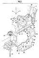
- FIG. 1 is a schematic perspective view showing a vehicle body floor structure of an embodiment according to the present invention, under a condition wherein a dash panel, a gusset plate and a bolt plate are exploded, as viewed from a lower side of a vehicle body toward forward and upper side thereof
- FIG. 2 is a schematic perspective view showing the vehicle body floor structure of the presently filed embodiment, under a condition where a floor reinforce and associated component parts are exploded, with assembled portion mainly between a front end of a side sill inner and a distal end of a cross member, that is, the cross member and associated component parts assembled to the vehicle body being viewed along a direction X, as shown in FIG.
- FIG. 3 is a perspective view showing the vehicle body floor structure of the presently filed embodiment in a condition where the floor reinforce and associated component parts, shown in the exploded form in FIG. 2 , are assembled
- FIG. 4 is a cross-sectional view taken on line A-A of FIG. 3
- FIG. 5 is a cross-sectional view taken on line B-B of FIG. 3
- FIG. 6 is a cross-sectional view taken on line C-C of FIG. 3 .
- x-axis designates a forward direction of the vehicle body
- y-axis designates a leftward direction of the vehicle body
- z-axis designates an upward direction of the vehicle body, with these axes forming a three-axis rectangular coordinate system.
- a floor panel 1 shown in a phantom line for the sake of convenience, has a front end connected to a dash panel 2.
- the dash panel 2 is formed of a vertical wall 2a, slanted toe board sections 2b, contiguous with a lower area of the vertical wall 2a, and a tunnel section 2c at a center in a vehicle-widthwise direction, with a front end of the floor panel 1 being overlapped on rear ends of the toe board sections 2b and the tunnel section 2c.
- each side sill 3 disposed beneath a lower surface of the floor panel 1 and extending in a fore and aft direction of the vehicle body on both sides thereof in the vehicle-widthwise direction are a pair of side sills 3 (shown in a phantom line in FIG. 1 for the sake of convenience), each formed in a closed cross-sectional configuration, with each side sill 3 having a side sill inner 3A serving as a structural member at an inside area in the vehicle-widthwise direction.
- a cross member 4 Joined to the lower surface of the floor panel 1 at an area close proximity to a junction between the floor panel 1 and the dash panel 2 is a cross member 4 that is connected to the side sill inners 3A of the pair of side sills 3, respectively, with the floor panel 1 and the cross member 4 forming a closed cross-sectional configuration extending in the vehicle-widthwise direction.
- the cross member 4 may include two-piece members that are connected to the center tunnel (not shown) of the floor panel 1, which is connected to the tunnel section 2c of the dash panel 2, respectively.
- the cross member 4 has a substantially hat-shaped cross-section formed of a bottom wall 4a, front walls 4b formed in opposition to one another, a rear wall 4c and flanges 4d bent and formed at upper edges of the front wall 4b and the rear wall 4c, respectively.
- the cross member 4 is joined to the lower surface of the floor panel 1 at the flanges 4d, respectively, and has flanges 4d', which is formed at distal ends of the bottom wall 4a to be contiguous with the respective flanges 4d of the relevant front walls 4b, joined to the side sill inners 3A, respectively, with an upper area of the cross member 4 being closed with the floor panel 1 while both ends of the cross member 4 in the vehicle-widthwise direction are closed with the side sill inners 3A, respectively.
- the bottom wall 4a of the cross member 4 is formed in step portions extending toward both ends of the bottom wall 4 in the vehicle-widthwise direction and oriented downward such that the closed cross-sectional sections are enlarged.
- the cross member 4 is formed in substantial L-shape, in cross-section with the rear wall 4c being removed, at areas of the cross member 4 whose closed cross-sectional sections are enlarged.
- each gusset plates 5 is joined to a front end wall of each side sill inner 3A and a front face of the dash panel 2 at a side end thereof, thereby reinforcing the vehicle body floor structure.
- FIGS. 2 to 4 and FIG. 6 additionally, in a front corner area surrounded by the dash panel 2, a front end portion of the side sill inner 3A and the front wall 4b of the cross member 4 at the distal end thereof in the vehicle-widthwise direction, the dash panel 2, a floor reinforce 6 is joined to and placed on the dash panel 2, the side sill inner 3A and the cross member 4, thereby a front corner closed cross-sectional section S 1.
- the floor reinforce 6 is formed in a substantial L-shape in cross-section defined by a bottom wall 6A, a side wall 6B placed inward in the vehicle-widthwise direction, a front wall 6C and a tilt wall 6D through which the side wall 6B and the front wall 6C are interconnected.
- the floor reinforce 6 is fixed in place such that the bottom wall 6A is joined to an outer surface of the bottom wall 4a of the cross member 4 and the front wall 6C is fixedly secured to the gusset plate 5 by fastening a bolt 10a via a bolt insertion hole 6a and a threaded bore 5a of the gusset plate 5 after which an upper edge flange 6C' is overlapped on and joined to a front face of the toe board 2b of the dash panel 2.
- the floor reinforce 6 is fixed in place such that nuts 11a, 11b are fastened to bolts 7a, 7b provided on the bolt plate 7, which is joined to and placed beneath a lower surface of the toe board section 2b, via bolt insertion holes 6b, 6c formed in a wall portion of the tilt wall 6D and the upper edge flange 6D', respectively.
- a rib wall 8 by which the front corner closed cross-sectional section S1 is vertically defined in plural chambers, more particularly, in two chambers.
- the rib wall 8 is formed in a substantial L-shape in cross-section with a vertical wall 8A, extending along a side face of the side sill inner 3A, and a transverse rib wall 8B bent from and formed at an upper end of the vertical wall 8A in a substantially horizontal plane.
- the transverse rib wall 8B has a flange 8a bent and formed such that the flange 8a is formed in a tilt configuration in conformity to a tilted shape of the tilt wall 6D of the floor reinforce 6 and continuously extending from straddling a lower edge of the vertical wall 8A, a front edge of the transverse rib wall 8B and a side edge of the transverse rib wall 8B.
- the rib 8 is assembled such that the flanges 8a, formed at the lower edge and front edge of the vertical wall 8A, are preliminarily held in contact with a lower surface of the side sill inner 3A and the front face of the gusset plate 5 after which the flange 8a is fixedly secured to the gusset plate 5 by fastening a bolt 10b to a threaded bore 5b, formed in a lower area of the gusset plate 5, via a bolt insertion hole 8b formed in the flange 8a at a lower area thereof.
- the rib wall 8 is placed so as to allow the bolt 7a, provided on the bolt plate 7, to be inserted through a bolt insertion hole 8c, formed in the flange 8a at the upper edge of the rib wall 8B, upon which both the flange 8a of the rib wall 8 and the tilt wall 6D of the floor reinforce 6 are tightened together in a fixed place by fastening the nut 11 a to the bolt 7a.
- a rear edge of the rib wall 8 is brought into abutment with or close contact with the front wall 4b of the cross member 4, thereby vertically defining the front corner closed cross-sectional section S 1 in the two chambers.
- a rear corner closed cross-sectional section S2 formed in an area on a substantially rearward extension of the front corner closed cross-sectional section S1 at a rear corner area surrounded by the rear wall 4c at the distal end of the cross member 4, the side sill inner 3A and the floor panel 1 is a rear corner closed cross-sectional section S2 in which a floor reinforce extension 12 is joined to the side sill inner 3A and the floor panel 1, with the floor reinforce extension 12 straddling the cross member 4, the side sill inner 3A and the floor panel 1.
- the floor reinforce extension 12 is formed in a box-like configuration so as to cover an area, from which the rear wall 4c is cut away at the distal end of the cross member 4, with a bottom wall 12a and a front wall 12b of the floor reinforce 12 being joined to the bottom wall 4a and an inner surface of the front wall 4b of the cross member 4 such that the floor reinforce 12 partly overlaps on the cross member 4.
- a nut plate 25 having a substantial U-shape cross-section, provided with a body-mounting nut 24 that will be described later.
- the gusset plate 13 having a substantial U-shape cross-section is joined to and placed on the nut plate 25 and a rear wall 12c of the floor reinforce 12 in a way to straddle these component parts, thereby compensating a decrease in rigidity of the cross member 4 caused by cutting out the rear wall 4c at the ends of the cross member 4.
- a vehicle body of the type having a cabin body CB formed with a vehicle compartment C, is mounted on the chassis frames 20 and has mount brackets 21 each throwing out to and joined to a side portion of each chassis frame 20.
- Attached on the mount bracket 21 is an insulator 22 that is held in abutting engagement with a lower side of overlapped portions among the bottom wall 4a of the cross member 4, the bottom wall 6A of the floor reinforce 6, and the bottom wall 12a of the floor reinforce extension 12, after which the insulator 22 is tightened to and fixed in place on the floor reinforce extension 12 by fastening a body mount bolt 23 and nut 24, thereby allowing the cabin body to be mounted on the chassis frames 20.
- a foot rest 14 joined to and placed on the toe board 2b of the dash panel 2 on a side facing the vehicle compartment C is a foot rest 14 formed in a box-like configuration at an area directly above the front corner closed cross-sectional section S1 to form a vehicle compartment-side closed cross-sectional section S3 that is located substantially and directly above the front corner closed cross-sectional section S 1.
- reference numeral 15 designates a dash side panel connected to the dash panel 2 and the side sills 3.
- the floor reinforce 6 straddles and is joined to the front ends of the side sill inners 3A, the distal ends of the cross member 4 in the vehicle-widthwise direction and the dash panel 2, thereby forming the front corner closed cross-sectional sections S1.
- the front corner closed cross-sectional section S1 is able to ensure an adequate withstand resistance with the resultant improvement in a load dispersion effect on the floor reinforce 6, the cross member 4 and the dash panel 2, thereby enabling the minimization in deformations of the front ends of the side sills 3 to ensure a living space in front of the cabin.
- the presence of a layout partially provided with the floor reinforces 6 results in increases in rigidities of the front corner sections surrounded by the front wall 4b of the cross member 4, the front end portions of the side sill inners 3A and the dash panel 2, enabling further advantageous effects to result in weight and cost than those obtained upon entirely increasing a plate thickness or a material quality of the side sills 3.
- the front corner closed cross-sectional section S1 is enabled to have further increased strength and rigidity.
- the rib wall 8 may include plural wall components by which the front corner closed cross-sectional section S1 is divided into a plurality of spaced in the vehicle-widthwise direction to enable improved rigidity to be obtained.
- the front reinforce extension 12 straddles and is joined to the rear corner section, surrounded by the rear wall 4c of the cross member 4 at the end thereof in the vehicle-widthwise direction, the side sill inner 3A and the floor panel 1 upon which the rear corner closed cross-sectional section S2 is defined on an extension substantially rearward of the front corner closed cross-sectional section S1, an area around the front end of the side sill 3 has further increased strength and rigidity in the fore and aft direction and in the vehicle-widthwise direction.
- the box-like foot rest 14 is joined to and placed on the toe board 2b of the dash panel 2 on the side facing the vehicle compartment thereby forming the closed cross-sectional sections S3 on a side facing the vehicle compartment in the area directly above the front corner closed cross-sectional section S1, the area around the front end of the side sill 3 has further increased strength and rigidity, enabling a deformation and ingression stroke of the dash side portion, oriented toward the vehicle compartment during a frontal collision of the vehicle, to be minimized to a value as less as possible.
Landscapes
- Engineering & Computer Science (AREA)
- Chemical & Material Sciences (AREA)
- Combustion & Propulsion (AREA)
- Transportation (AREA)
- Mechanical Engineering (AREA)
- Body Structure For Vehicles (AREA)
Description
- The present invention relates to a vehicle body floor structure and, more particularly, to a vehicle body floor structure around an assembled portion, between a front end of a side sill and an end of a dash panel in a vehicle-widthwise direction, of a vehicle body floor section of an automobile.
- Japanese Patent Application Laid-open Publication No.
2000-225966 Page 3 andFIG. 4 ). - Another prior art document
JP58-067569 - However, upon studies conducted by the present inventor, such a structure in which the front ends of the side sills are reinforced by the reinforce member is effective in cases where a front wheel is moved backward in a straight direction to be brought into colliding contact with the vehicle body during a frontal collision of the vehicle. In the meanwhile, it is conceived that in cases where the front wheel is moved inward in the vehicle-widthwise direction along an oblique direction thereof to be brought into colliding contact with the vehicle body, the front end of the side sill is caused to deform inward in the vehicle-widthwise direction.
- To address such an issue, a need arises for the side sill to have an increased plate thickness or to be made of material with increased strength, causing factors to occur in increase in weight and cost.
- The present invention has been completed with the above study in mind conducted by the present inventor and has an object to provide a vehicle body floor structure, additionally provided with a partially formed reinforce, which is able to adequately withstand both a rearward colliding input, applied to a front end of the side sill, and a colliding input applied to the vehicle body in a vehicle-widthwise direction.
- To achieve the above object, in one aspect according to the present invention, there is provided a vehicle body floor structure comprising: a cross member connected to at least one of a pair of side sill inners, extending in a fore and aft direction of a vehicle body at both ends of the cross member in a widthwise direction of the vehicle body, and associated with a lower surface of a front end of a floor panel at an area close proximity to a dash panel to form a closed cross-sectional section extending in the widthwise direction; and a floor reinforce joined to the dash panel, the side sill inner and the cross member at a front corner area surrounded by the dash panel, a front end of the at least one of the side sill inners, and a front wall of the end of the cross member to form a front corner closed cross-sectional section.
- Other and further features, advantages, and benefits of the present invention will become more apparent from the following description taken in conjunction with the following drawings.
-
-
FIG. 1 is a schematic perspective view showing a vehicle body floor structure of an embodiment according to the present invention, under a condition wherein a dash panel, a gusset plate and a bolt plate are exploded, as viewed from a lower side of a vehicle body toward forward and upper side thereof; -
FIG. 2 is a schematic perspective view showing the vehicle body floor structure of the presently filed embodiment, under a condition where a floor reinforce and associated component parts are exploded, with assembled portion mainly between a front end of a side sill inner and a distal end of a cross member, that is, the cross member and associated component parts assembled to the vehicle body being viewed along a direction X, as shown inFIG. 1 , which is oriented from an inner and lower side of the vehicle body toward an outer and upper side thereof; -
FIG. 3 is a perspective view showing the vehicle body floor structure of the presently filed embodiment in a condition where the floor reinforce and associated component parts, shown in the exploded form inFIG. 2 , are assembled; -
FIG. 4 is a cross-sectional view taken on line A-A ofFIG. 3 ; -
FIG. 5 is a cross-sectional view taken on line B-B ofFIG. 3 ; and -
FIG. 6 is a cross-sectional view taken on line C-C ofFIG. 3 . - Hereinafter, a vehicle body floor structure of an embodiment according to the present invention is described below with reference to
FIGS. 1 to 6 . Incidentally, the presently filed embodiment is described taking a structure, in which a cabin body with a vehicle compartment is mounted on a chassis fame, as an example. -
FIG. 1 is a schematic perspective view showing a vehicle body floor structure of an embodiment according to the present invention, under a condition wherein a dash panel, a gusset plate and a bolt plate are exploded, as viewed from a lower side of a vehicle body toward forward and upper side thereof,FIG. 2 is a schematic perspective view showing the vehicle body floor structure of the presently filed embodiment, under a condition where a floor reinforce and associated component parts are exploded, with assembled portion mainly between a front end of a side sill inner and a distal end of a cross member, that is, the cross member and associated component parts assembled to the vehicle body being viewed along a direction X, as shown inFIG. 1 , which is oriented from an inner and lower side of the vehicle body toward an outer and upper side thereof,FIG. 3 is a perspective view showing the vehicle body floor structure of the presently filed embodiment in a condition where the floor reinforce and associated component parts, shown in the exploded form inFIG. 2 , are assembled,FIG. 4 is a cross-sectional view taken on line A-A ofFIG. 3 ,FIG. 5 is a cross-sectional view taken on line B-B ofFIG. 3 , andFIG. 6 is a cross-sectional view taken on line C-C ofFIG. 3 . Incidentally, in the drawing figures, x-axis designates a forward direction of the vehicle body; y-axis designates a leftward direction of the vehicle body; and z-axis designates an upward direction of the vehicle body, with these axes forming a three-axis rectangular coordinate system. - As shown in
FIG. 1 , with a vehicle body floor structure S of the presently filed embodiment, afloor panel 1, shown in a phantom line for the sake of convenience, has a front end connected to adash panel 2. - More particularly, the
dash panel 2 is formed of avertical wall 2a, slantedtoe board sections 2b, contiguous with a lower area of thevertical wall 2a, and atunnel section 2c at a center in a vehicle-widthwise direction, with a front end of thefloor panel 1 being overlapped on rear ends of thetoe board sections 2b and thetunnel section 2c. - Also as shown in
FIG. 2 , further, disposed beneath a lower surface of thefloor panel 1 and extending in a fore and aft direction of the vehicle body on both sides thereof in the vehicle-widthwise direction are a pair of side sills 3 (shown in a phantom line inFIG. 1 for the sake of convenience), each formed in a closed cross-sectional configuration, with eachside sill 3 having a side sill inner 3A serving as a structural member at an inside area in the vehicle-widthwise direction. - Joined to the lower surface of the
floor panel 1 at an area close proximity to a junction between thefloor panel 1 and thedash panel 2 is across member 4 that is connected to theside sill inners 3A of the pair ofside sills 3, respectively, with thefloor panel 1 and thecross member 4 forming a closed cross-sectional configuration extending in the vehicle-widthwise direction. Of course, thecross member 4 may include two-piece members that are connected to the center tunnel (not shown) of thefloor panel 1, which is connected to thetunnel section 2c of thedash panel 2, respectively. - More particularly, as shown in
FIGS. 2 and3 , thecross member 4 has a substantially hat-shaped cross-section formed of abottom wall 4a,front walls 4b formed in opposition to one another, arear wall 4c andflanges 4d bent and formed at upper edges of thefront wall 4b and therear wall 4c, respectively. That is, thecross member 4 is joined to the lower surface of thefloor panel 1 at theflanges 4d, respectively, and hasflanges 4d', which is formed at distal ends of thebottom wall 4a to be contiguous with therespective flanges 4d of the relevantfront walls 4b, joined to theside sill inners 3A, respectively, with an upper area of thecross member 4 being closed with thefloor panel 1 while both ends of thecross member 4 in the vehicle-widthwise direction are closed with theside sill inners 3A, respectively. - Further, the
bottom wall 4a of thecross member 4 is formed in step portions extending toward both ends of thebottom wall 4 in the vehicle-widthwise direction and oriented downward such that the closed cross-sectional sections are enlarged. Particularly, as shown inFIG. 4 , thecross member 4 is formed in substantial L-shape, in cross-section with therear wall 4c being removed, at areas of thecross member 4 whose closed cross-sectional sections are enlarged. - By the way, mainly as shown in
FIGS. 1 to 3 , eachgusset plates 5 is joined to a front end wall of each side sill inner 3A and a front face of thedash panel 2 at a side end thereof, thereby reinforcing the vehicle body floor structure. - As mainly shown in
FIGS. 2 to 4 andFIG. 6 , additionally, in a front corner area surrounded by thedash panel 2, a front end portion of the side sill inner 3A and thefront wall 4b of thecross member 4 at the distal end thereof in the vehicle-widthwise direction, thedash panel 2, afloor reinforce 6 is joined to and placed on thedash panel 2, the side sill inner 3A and thecross member 4, thereby a front corner closedcross-sectional section S 1. - In particular, the
floor reinforce 6 is formed in a substantial L-shape in cross-section defined by abottom wall 6A, aside wall 6B placed inward in the vehicle-widthwise direction, afront wall 6C and atilt wall 6D through which theside wall 6B and thefront wall 6C are interconnected. - The
floor reinforce 6 is fixed in place such that thebottom wall 6A is joined to an outer surface of thebottom wall 4a of thecross member 4 and thefront wall 6C is fixedly secured to thegusset plate 5 by fastening abolt 10a via abolt insertion hole 6a and a threadedbore 5a of thegusset plate 5 after which anupper edge flange 6C' is overlapped on and joined to a front face of thetoe board 2b of thedash panel 2. Additionally, thefloor reinforce 6 is fixed in place such thatnuts bolts bolt plate 7, which is joined to and placed beneath a lower surface of thetoe board section 2b, viabolt insertion holes tilt wall 6D and theupper edge flange 6D', respectively. - Further, as mainly shown in
FIGS. 2 to 4 andFIG. 6 , provided in the front corner closed cross-sectional section S1 is arib wall 8 by which the front corner closed cross-sectional section S1 is vertically defined in plural chambers, more particularly, in two chambers. - More particularly, the
rib wall 8 is formed in a substantial L-shape in cross-section with avertical wall 8A, extending along a side face of the side sill inner 3A, and atransverse rib wall 8B bent from and formed at an upper end of thevertical wall 8A in a substantially horizontal plane. Thetransverse rib wall 8B has aflange 8a bent and formed such that theflange 8a is formed in a tilt configuration in conformity to a tilted shape of thetilt wall 6D of the floor reinforce 6 and continuously extending from straddling a lower edge of thevertical wall 8A, a front edge of thetransverse rib wall 8B and a side edge of thetransverse rib wall 8B. - The
rib 8 is assembled such that theflanges 8a, formed at the lower edge and front edge of thevertical wall 8A, are preliminarily held in contact with a lower surface of the side sill inner 3A and the front face of thegusset plate 5 after which theflange 8a is fixedly secured to thegusset plate 5 by fastening abolt 10b to a threadedbore 5b, formed in a lower area of thegusset plate 5, via abolt insertion hole 8b formed in theflange 8a at a lower area thereof. In addition, during assembling the floor reinforce 6, therib wall 8 is placed so as to allow thebolt 7a, provided on thebolt plate 7, to be inserted through a bolt insertion hole 8c, formed in theflange 8a at the upper edge of therib wall 8B, upon which both theflange 8a of therib wall 8 and thetilt wall 6D of the floor reinforce 6 are tightened together in a fixed place by fastening thenut 11 a to thebolt 7a. Under an assembled status, therefore, a rear edge of therib wall 8 is brought into abutment with or close contact with thefront wall 4b of thecross member 4, thereby vertically defining the front corner closedcross-sectional section S 1 in the two chambers. - Further, as mainly shown in
FIGS. 2 to 4 , formed in an area on a substantially rearward extension of the front corner closed cross-sectional section S1 at a rear corner area surrounded by therear wall 4c at the distal end of thecross member 4, the side sill inner 3A and thefloor panel 1 is a rear corner closed cross-sectional section S2 in which afloor reinforce extension 12 is joined to the side sill inner 3A and thefloor panel 1, with thefloor reinforce extension 12 straddling thecross member 4, the side sill inner 3A and thefloor panel 1. - More particularly, the
floor reinforce extension 12 is formed in a box-like configuration so as to cover an area, from which therear wall 4c is cut away at the distal end of thecross member 4, with abottom wall 12a and afront wall 12b of the floor reinforce 12 being joined to thebottom wall 4a and an inner surface of thefront wall 4b of thecross member 4 such that the floor reinforce 12 partly overlaps on thecross member 4. - As mainly shown in
FIGS. 4 and5 , joined to and placed on an inner surface of theinner wall 12a is anut plate 25, having a substantial U-shape cross-section, provided with a body-mounting nut 24 that will be described later. Moreover, thegusset plate 13 having a substantial U-shape cross-section is joined to and placed on thenut plate 25 and arear wall 12c of the floor reinforce 12 in a way to straddle these component parts, thereby compensating a decrease in rigidity of thecross member 4 caused by cutting out therear wall 4c at the ends of thecross member 4. - As mainly shown in
FIG. 5 , with the presently filed embodiment, a vehicle body of the type, having a cabin body CB formed with a vehicle compartment C, is mounted on thechassis frames 20 and hasmount brackets 21 each throwing out to and joined to a side portion of eachchassis frame 20. Attached on themount bracket 21 is aninsulator 22 that is held in abutting engagement with a lower side of overlapped portions among thebottom wall 4a of thecross member 4, thebottom wall 6A of the floor reinforce 6, and thebottom wall 12a of the floor reinforceextension 12, after which theinsulator 22 is tightened to and fixed in place on the floor reinforceextension 12 by fastening abody mount bolt 23 andnut 24, thereby allowing the cabin body to be mounted on thechassis frames 20. - In the meanwhile, mainly as shown in
FIG. 4 , joined to and placed on thetoe board 2b of thedash panel 2 on a side facing the vehicle compartment C is afoot rest 14 formed in a box-like configuration at an area directly above the front corner closed cross-sectional section S1 to form a vehicle compartment-side closed cross-sectional section S3 that is located substantially and directly above the front corner closed cross-sectionalsection S 1. - Incidentally, in
FIGS. 5 and 6 ,reference numeral 15 designates a dash side panel connected to thedash panel 2 and theside sills 3. - As set forth above, with the vehicle body floor structure of the presently filed embodiment, the floor reinforce 6 straddles and is joined to the front ends of the
side sill inners 3A, the distal ends of thecross member 4 in the vehicle-widthwise direction and thedash panel 2, thereby forming the front corner closed cross-sectional sections S1. For this reason, even when the vehicle body encounters an impact input directed rearward from the front end of the side sill or directed inward in the vehicle-widthwise direction during a frontal collision of the vehicle, the front corner closed cross-sectional section S1 is able to ensure an adequate withstand resistance with the resultant improvement in a load dispersion effect on the floor reinforce 6, thecross member 4 and thedash panel 2, thereby enabling the minimization in deformations of the front ends of the side sills 3 to ensure a living space in front of the cabin. - Further, the presence of a layout partially provided with the floor reinforces 6 results in increases in rigidities of the front corner sections surrounded by the
front wall 4b of thecross member 4, the front end portions of theside sill inners 3A and thedash panel 2, enabling further advantageous effects to result in weight and cost than those obtained upon entirely increasing a plate thickness or a material quality of theside sills 3. - Further, due to the presence of the
rib wall 8 disposed in the front corner closed cross-sectional section S1 to allow the same to be vertically defined in plural spaces, the front corner closed cross-sectional section S1 is enabled to have further increased strength and rigidity. - Of course, the
rib wall 8 may include plural wall components by which the front corner closed cross-sectional section S1 is divided into a plurality of spaced in the vehicle-widthwise direction to enable improved rigidity to be obtained. - Further, due to a structure wherein the
front reinforce extension 12 straddles and is joined to the rear corner section, surrounded by therear wall 4c of thecross member 4 at the end thereof in the vehicle-widthwise direction, the side sill inner 3A and thefloor panel 1 upon which the rear corner closed cross-sectional section S2 is defined on an extension substantially rearward of the front corner closed cross-sectional section S1, an area around the front end of theside sill 3 has further increased strength and rigidity in the fore and aft direction and in the vehicle-widthwise direction. - Also, since the box-
like foot rest 14 is joined to and placed on thetoe board 2b of thedash panel 2 on the side facing the vehicle compartment thereby forming the closed cross-sectional sections S3 on a side facing the vehicle compartment in the area directly above the front corner closed cross-sectional section S1, the area around the front end of theside sill 3 has further increased strength and rigidity, enabling a deformation and ingression stroke of the dash side portion, oriented toward the vehicle compartment during a frontal collision of the vehicle, to be minimized to a value as less as possible. - Incidentally, while the presently filed embodiment has been described taking the vehicle of the type in which the cabin body is mounted on the
chassis frames 20 as an example, it is, of course, to be noted that the present invention may have application to a vehicle with a monocoque body construction. - Although the invention has been described above by reference to a certain embodiment of the invention, the invention is not limited to the embodiment described above. Modifications and variations of the embodiment described above will occur to those skilled in the art, in light of the teachings. The scope of the invention is defined with reference to the following claims.
Claims (10)
- A vehicle body floor structure (S) caracterised by :a cross member (4) connected to at least one of a pair of side sill inners (3A), extending in a fore and aft direction (x) of a vehicle body at both ends of the cross member in a widthwise direction (y) of the vehicle body, and associated with a lower surface of a front end of a floor panel (1) at an area close proximity to a dash panel (2) to form a closed cross-sectional section extending in the widthwise direction; anda floor reinforce (6) joined to the dash panel, the side sill inner and the cross member at a front corner area surrounded by the dash panel, a front end of the at least one of the side sill inners, and a front wall of the end of the cross member to form a front corner closed cross-sectional section (S1).
- The vehicle body floor structure according to claim 1, wherein the floor reinforce (6) is fixed to a gusset plate (5) that is joined to a front face of a side end of the dash panel (2) and a front end wall of the side sill inner (3A) in an area straddling the same.
- The vehicle body floor structure according to claim 1 or 2, wherein the floor reinforce (6) is fixed to the cross member (4) via a mount fixing structure (22 to 25).
- The vehicle body floor structure according to any of claims 1 to 3, wherein the floor reinforce (6) is fixed to the dash panel (2) via a bolt plate (7) fixed to the dash panel.
- The vehicle body floor structure according to any of claims 1 to 4, wherein the floor reinforce (6) has an L-shape in cross-section.
- The vehicle body floor structure according to any of claims 1 to 5, further comprising a rib wall (8) disposed in the front corner closed cross-sectional section (S1) for defining a plurality of spaces in at least one of a vertical direction (z) of the vehicle body and the widthwise direction (y) thereof.
- The vehicle body floor structure according to any of claims 1 to 6, further comprising a floor reinforce extension (12), joined to the cross member (4), the at least one of the side sill inners (3A) and the floor panel (1) at a rear corner area surrounded by a terminal rear wall of the cross member, the at least one side sill inner and the floor panel, the floor reinforce extension forming a rear corner closed cross-sectional section (S2) in an area rearward of the front corner closed cross-sectional section (S1).
- The vehicle body floor structure according to claim 7, wherein the floor reinforce extension (12) covers a cutout portion of the cross member (4).
- The vehicle body floor structure according to claim 7, wherein a mount fixing structure (22 to 25) is attached to the floor reinforce extension (12) and the cross member (4).
- The vehicle body floor structure according to any of claims 1 to 9, further comprising a box-like foot rest (14), joined to and fixed on a surface, facing a vehicle compartment (C), of the dash panel (2), the box-like foot rest forming a compartment sided closed cross-sectional section (S3) directly above the front corner closed cross-sectional section (S1).
Applications Claiming Priority (2)
| Application Number | Priority Date | Filing Date | Title |
|---|---|---|---|
| JP2004137198A JP3988745B2 (en) | 2004-05-06 | 2004-05-06 | Body floor structure |
| JP2004137198 | 2004-05-06 |
Publications (3)
| Publication Number | Publication Date |
|---|---|
| EP1595772A2 EP1595772A2 (en) | 2005-11-16 |
| EP1595772A3 EP1595772A3 (en) | 2006-05-10 |
| EP1595772B1 true EP1595772B1 (en) | 2008-05-21 |
Family
ID=34940752
Family Applications (1)
| Application Number | Title | Priority Date | Filing Date |
|---|---|---|---|
| EP05252219A Expired - Lifetime EP1595772B1 (en) | 2004-05-06 | 2005-04-08 | Vehicle body floor structure |
Country Status (5)
| Country | Link |
|---|---|
| US (1) | US7163259B2 (en) |
| EP (1) | EP1595772B1 (en) |
| JP (1) | JP3988745B2 (en) |
| CN (1) | CN100509523C (en) |
| DE (1) | DE602005006885D1 (en) |
Families Citing this family (32)
| Publication number | Priority date | Publication date | Assignee | Title |
|---|---|---|---|---|
| JPS6358106A (en) * | 1986-08-29 | 1988-03-12 | Hitachi Ltd | Straightness measuring apparatus for feed table |
| DE102004011786B4 (en) * | 2004-03-09 | 2006-06-29 | Wilhelm Karmann Gmbh | Method for increasing the crash resistance of a motor vehicle and thus used block element |
| EP1712454B1 (en) * | 2005-04-15 | 2007-08-15 | HONDA MOTOR CO., Ltd. | Floor structure of vehicle body |
| JP4404036B2 (en) * | 2005-09-21 | 2010-01-27 | トヨタ自動車株式会社 | Vehicle rear structure |
| US7416242B2 (en) * | 2006-03-29 | 2008-08-26 | Chrysler Llc | Reinforcement plate |
| ITMI20061478A1 (en) * | 2006-07-27 | 2008-01-28 | Iveco Spa | FRONT CROSSBAR FOR TRUCK CABIN, CAB AND RELATED MANUFACTURING METHOD |
| JP4293221B2 (en) * | 2006-10-06 | 2009-07-08 | トヨタ自動車株式会社 | Vehicle body support structure |
| US7367602B1 (en) | 2007-06-28 | 2008-05-06 | Toyota Motor Engineering & Manufacturing North America, Inc. | Storage bin assembly |
| US20090174220A1 (en) * | 2008-01-07 | 2009-07-09 | Gm Global Technology Operations, Inc. | Vehicle Body Structure with Linking Bracket for a Vehicle Side Pillar |
| JP2009234495A (en) * | 2008-03-28 | 2009-10-15 | Mazda Motor Corp | Frame structure of automobile |
| JP2010120404A (en) * | 2008-11-17 | 2010-06-03 | Toyota Motor Corp | Floor structure of vehicle |
| JP5201216B2 (en) * | 2008-12-08 | 2013-06-05 | トヨタ自動車株式会社 | Body side structure |
| JP5447801B2 (en) * | 2009-06-26 | 2014-03-19 | スズキ株式会社 | Rear suspension spring support structure |
| CN102069848B (en) * | 2009-11-19 | 2013-04-24 | 本田技研工业株式会社 | Mounting structure of subframe and manufacturing method of elastic assembly of mounting sub-frame of vehicle |
| JP5971059B2 (en) * | 2012-09-28 | 2016-08-17 | マツダ株式会社 | Vehicle structure |
| DE102012024631A1 (en) * | 2012-12-17 | 2014-06-18 | GM Global Technology Operations LLC (n. d. Ges. d. Staates Delaware) | Motor vehicle body structure and method for producing a motor vehicle body structure |
| US9079619B2 (en) * | 2013-08-14 | 2015-07-14 | Ford Global Technologies, Llc | Vehicle frame component |
| JP6172062B2 (en) * | 2014-06-13 | 2017-08-02 | トヨタ車体株式会社 | Vehicle mounting structure |
| US9586631B2 (en) * | 2014-06-30 | 2017-03-07 | Ford Global Technologies, Llc | Cast load structure for vehicle body to frame mount |
| JP6185437B2 (en) * | 2014-07-18 | 2017-08-23 | トヨタ自動車九州株式会社 | Vehicle front structure |
| US9221317B1 (en) | 2014-07-31 | 2015-12-29 | GM Global Technology Operations LLC | Releasable chassis mount |
| JP6384257B2 (en) * | 2014-10-14 | 2018-09-05 | 三菱自動車工業株式会社 | Vehicle floor structure |
| US9238487B1 (en) * | 2014-11-04 | 2016-01-19 | Toyota Motor Engineering & Manufacturing North America, Inc. | Inner front side member to rocker support reinforcement gussets for vehicle front structures |
| US11097782B2 (en) | 2014-11-24 | 2021-08-24 | Tesseract Structural Innovations, Inc. | Sill beam uniform deceleration unit |
| US9694853B2 (en) | 2015-11-25 | 2017-07-04 | Ford Global Technologies, Llc | Underbody mounted rim engagement member |
| JP6647248B2 (en) * | 2017-07-05 | 2020-02-14 | 本田技研工業株式会社 | Body structure |
| KR102383248B1 (en) * | 2017-10-12 | 2022-04-05 | 현대자동차 주식회사 | Mountinb unit for rear suspension |
| WO2019204350A1 (en) * | 2018-04-16 | 2019-10-24 | Tesseract Structural Innovations, Inc. | Uniform deceleration unit |
| US11180196B2 (en) * | 2019-01-14 | 2021-11-23 | Fca Us Llc | Structural joining part for sorb impact events |
| CN112776905B (en) * | 2021-03-12 | 2022-06-07 | 北京汽车集团越野车有限公司 | Suspension mounting point additional strengthening, suspension installation assembly and vehicle that has it |
| CN113147923B (en) * | 2021-03-12 | 2022-08-02 | 北京汽车集团越野车有限公司 | Suspension mounting point additional strengthening, suspension installation assembly and vehicle that has it |
| KR20230028972A (en) * | 2021-08-23 | 2023-03-03 | 현대모비스 주식회사 | Fastening apparatus for vehicle |
Family Cites Families (19)
| Publication number | Priority date | Publication date | Assignee | Title |
|---|---|---|---|---|
| JPS5911464B2 (en) * | 1978-11-10 | 1984-03-15 | 日産自動車株式会社 | car body structure |
| JPS5867569A (en) | 1981-10-16 | 1983-04-22 | Mazda Motor Corp | Automotive body structure |
| JPS59109468A (en) | 1982-12-16 | 1984-06-25 | Nissan Motor Co Ltd | Car body structure |
| US4669776A (en) * | 1985-03-19 | 1987-06-02 | Mazda Motor Corporation | Front body construction for motor vehicle |
| US4669777A (en) * | 1985-04-23 | 1987-06-02 | Mazda Motor Corporation | Front body structure for front engine type motor vehicle |
| IT1210827B (en) * | 1987-06-23 | 1989-09-29 | Fiat Auto Spa | MODULAR BODY ELEMENT FOR CARS |
| JPH0547752Y2 (en) * | 1987-08-04 | 1993-12-16 | ||
| JP2000225966A (en) | 1999-02-05 | 2000-08-15 | Suzuki Motor Corp | Car front body structure |
| DE19954296C2 (en) * | 1999-11-11 | 2003-06-18 | Porsche Ag | vehicle |
| KR100339216B1 (en) * | 1999-12-31 | 2002-05-31 | 이계안 | reinforcement structure for front pillar portion of automobile |
| US6364358B1 (en) | 2000-03-21 | 2002-04-02 | Honda Giken Kogyo Kabushiki Kaisha | Side sill load path initiator |
| JP2002154458A (en) * | 2000-11-24 | 2002-05-28 | Fuji Heavy Ind Ltd | Body front structure |
| US6679546B2 (en) * | 2001-06-12 | 2004-01-20 | Mazda Motor Corporation | Front body structure of vehicle |
| JP4010169B2 (en) * | 2002-04-09 | 2007-11-21 | 三菱自動車工業株式会社 | Body structure |
| DE10232842A1 (en) | 2002-07-19 | 2004-02-05 | Volkswagen Ag | Ground stiffening structure on motor vehicles |
| JP4346313B2 (en) | 2003-01-08 | 2009-10-21 | 富士重工業株式会社 | Auto body front structure |
| JP4346317B2 (en) | 2003-01-16 | 2009-10-21 | 富士重工業株式会社 | Auto body front structure |
| KR100527119B1 (en) * | 2003-04-15 | 2005-11-09 | 현대자동차주식회사 | Stiffness increasing structure of front end module combination area on automobile fender apron |
| JP4207806B2 (en) * | 2004-03-02 | 2009-01-14 | 日産自動車株式会社 | Body floor structure |
-
2004
- 2004-05-06 JP JP2004137198A patent/JP3988745B2/en not_active Expired - Fee Related
-
2005
- 2005-04-06 US US11/099,649 patent/US7163259B2/en not_active Expired - Fee Related
- 2005-04-08 DE DE602005006885T patent/DE602005006885D1/en not_active Expired - Lifetime
- 2005-04-08 EP EP05252219A patent/EP1595772B1/en not_active Expired - Lifetime
- 2005-04-29 CN CNB2005100687039A patent/CN100509523C/en not_active Expired - Fee Related
Also Published As
| Publication number | Publication date |
|---|---|
| CN1693130A (en) | 2005-11-09 |
| JP3988745B2 (en) | 2007-10-10 |
| DE602005006885D1 (en) | 2008-07-03 |
| EP1595772A3 (en) | 2006-05-10 |
| CN100509523C (en) | 2009-07-08 |
| US7163259B2 (en) | 2007-01-16 |
| US20050248185A1 (en) | 2005-11-10 |
| JP2005319830A (en) | 2005-11-17 |
| EP1595772A2 (en) | 2005-11-16 |
Similar Documents
| Publication | Publication Date | Title |
|---|---|---|
| EP1595772B1 (en) | Vehicle body floor structure | |
| JP7167630B2 (en) | vehicle front structure | |
| US10875582B2 (en) | Vehicle body lower structure | |
| US11661115B2 (en) | Body structure for an electrically operated vehicle | |
| EP2076421B1 (en) | Vehicle front structure | |
| EP0937631B1 (en) | Automobile body frame | |
| EP1886902B1 (en) | Vehicle front structure | |
| US8029046B2 (en) | Front vehicle body structure | |
| CN100519309C (en) | Vehicle body front structure | |
| EP2740650B1 (en) | Vehicle body rear structure | |
| CN105473426B (en) | Vehicle body front structure | |
| US8702158B2 (en) | Structure for vehicle body front portion | |
| CN102310886B (en) | Front body structure | |
| JP2004155219A (en) | Car body rear structure | |
| US12187110B2 (en) | Body structure for an electrically operated vehicle | |
| JP7519032B2 (en) | Electric vehicle undercarriage | |
| CN107021136A (en) | Vehicle body front structure | |
| EP2586682B1 (en) | Structure of front section of vehicle body | |
| JP4556320B2 (en) | Lower body structure of the vehicle | |
| CN120922243A (en) | Frame member for vehicle and front structure of vehicle body | |
| JP2002308151A (en) | Cab floor structure for cab-over type vehicle | |
| JP4069748B2 (en) | Vehicle front structure | |
| CN109878576B (en) | Vehicle front structure | |
| JP2025177945A (en) | Vehicle undercarriage | |
| CN121019708A (en) | Lower dashboard |
Legal Events
| Date | Code | Title | Description |
|---|---|---|---|
| PUAI | Public reference made under article 153(3) epc to a published international application that has entered the european phase |
Free format text: ORIGINAL CODE: 0009012 |
|
| 17P | Request for examination filed |
Effective date: 20050421 |
|
| AK | Designated contracting states |
Kind code of ref document: A2 Designated state(s): AT BE BG CH CY CZ DE DK EE ES FI FR GB GR HU IE IS IT LI LT LU MC NL PL PT RO SE SI SK TR |
|
| AX | Request for extension of the european patent |
Extension state: AL BA HR LV MK YU |
|
| PUAL | Search report despatched |
Free format text: ORIGINAL CODE: 0009013 |
|
| AK | Designated contracting states |
Kind code of ref document: A3 Designated state(s): AT BE BG CH CY CZ DE DK EE ES FI FR GB GR HU IE IS IT LI LT LU MC NL PL PT RO SE SI SK TR |
|
| AX | Request for extension of the european patent |
Extension state: AL BA HR LV MK YU |
|
| AKX | Designation fees paid |
Designated state(s): DE FR GB |
|
| GRAP | Despatch of communication of intention to grant a patent |
Free format text: ORIGINAL CODE: EPIDOSNIGR1 |
|
| GRAS | Grant fee paid |
Free format text: ORIGINAL CODE: EPIDOSNIGR3 |
|
| GRAA | (expected) grant |
Free format text: ORIGINAL CODE: 0009210 |
|
| AK | Designated contracting states |
Kind code of ref document: B1 Designated state(s): DE FR GB |
|
| REG | Reference to a national code |
Ref country code: GB Ref legal event code: FG4D |
|
| REF | Corresponds to: |
Ref document number: 602005006885 Country of ref document: DE Date of ref document: 20080703 Kind code of ref document: P |
|
| PLBE | No opposition filed within time limit |
Free format text: ORIGINAL CODE: 0009261 |
|
| STAA | Information on the status of an ep patent application or granted ep patent |
Free format text: STATUS: NO OPPOSITION FILED WITHIN TIME LIMIT |
|
| 26N | No opposition filed |
Effective date: 20090224 |
|
| PGFP | Annual fee paid to national office [announced via postgrant information from national office to epo] |
Ref country code: GB Payment date: 20100325 Year of fee payment: 6 |
|
| PGFP | Annual fee paid to national office [announced via postgrant information from national office to epo] |
Ref country code: FR Payment date: 20100521 Year of fee payment: 6 |
|
| PGFP | Annual fee paid to national office [announced via postgrant information from national office to epo] |
Ref country code: DE Payment date: 20100430 Year of fee payment: 6 |
|
| GBPC | Gb: european patent ceased through non-payment of renewal fee |
Effective date: 20110408 |
|
| REG | Reference to a national code |
Ref country code: FR Ref legal event code: ST Effective date: 20111230 |
|
| PG25 | Lapsed in a contracting state [announced via postgrant information from national office to epo] |
Ref country code: DE Free format text: LAPSE BECAUSE OF NON-PAYMENT OF DUE FEES Effective date: 20111101 Ref country code: FR Free format text: LAPSE BECAUSE OF NON-PAYMENT OF DUE FEES Effective date: 20110502 |
|
| REG | Reference to a national code |
Ref country code: DE Ref legal event code: R119 Ref document number: 602005006885 Country of ref document: DE Effective date: 20111101 |
|
| PG25 | Lapsed in a contracting state [announced via postgrant information from national office to epo] |
Ref country code: GB Free format text: LAPSE BECAUSE OF NON-PAYMENT OF DUE FEES Effective date: 20110408 |