JP6185437B2 - Vehicle front structure - Google Patents

Vehicle front structure Download PDF

Info

Publication number
JP6185437B2
JP6185437B2 JP2014147585A JP2014147585A JP6185437B2 JP 6185437 B2 JP6185437 B2 JP 6185437B2 JP 2014147585 A JP2014147585 A JP 2014147585A JP 2014147585 A JP2014147585 A JP 2014147585A JP 6185437 B2 JP6185437 B2 JP 6185437B2
Authority
JP
Japan
Prior art keywords
gusset
vehicle body
vehicle
panel
width direction
Prior art date
Legal status (The legal status is an assumption and is not a legal conclusion. Google has not performed a legal analysis and makes no representation as to the accuracy of the status listed.)
Active
Application number
JP2014147585A
Other languages
Japanese (ja)
Other versions
JP2016022813A (en
Inventor
泰 鳥川
泰 鳥川
茂 加治
茂 加治
健二 千葉
健二 千葉
Current Assignee (The listed assignees may be inaccurate. Google has not performed a legal analysis and makes no representation or warranty as to the accuracy of the list.)
Toyota Motor Corp
Toyota Motor Kyushu Inc
Original Assignee
Toyota Motor Corp
Toyota Motor Kyushu Inc
Priority date (The priority date is an assumption and is not a legal conclusion. Google has not performed a legal analysis and makes no representation as to the accuracy of the date listed.)
Filing date
Publication date
Application filed by Toyota Motor Corp, Toyota Motor Kyushu Inc filed Critical Toyota Motor Corp
Priority to JP2014147585A priority Critical patent/JP6185437B2/en
Priority to US14/797,906 priority patent/US9821853B2/en
Publication of JP2016022813A publication Critical patent/JP2016022813A/en
Application granted granted Critical
Publication of JP6185437B2 publication Critical patent/JP6185437B2/en
Active legal-status Critical Current
Anticipated expiration legal-status Critical

Links

Images

Classifications

    • BPERFORMING OPERATIONS; TRANSPORTING
    • B62LAND VEHICLES FOR TRAVELLING OTHERWISE THAN ON RAILS
    • B62DMOTOR VEHICLES; TRAILERS
    • B62D25/00Superstructure or monocoque structure sub-units; Parts or details thereof not otherwise provided for
    • B62D25/02Side panels
    • B62D25/025Side sills thereof
    • BPERFORMING OPERATIONS; TRANSPORTING
    • B62LAND VEHICLES FOR TRAVELLING OTHERWISE THAN ON RAILS
    • B62DMOTOR VEHICLES; TRAILERS
    • B62D25/00Superstructure or monocoque structure sub-units; Parts or details thereof not otherwise provided for
    • B62D25/04Door pillars ; windshield pillars
    • BPERFORMING OPERATIONS; TRANSPORTING
    • B62LAND VEHICLES FOR TRAVELLING OTHERWISE THAN ON RAILS
    • B62DMOTOR VEHICLES; TRAILERS
    • B62D25/00Superstructure or monocoque structure sub-units; Parts or details thereof not otherwise provided for
    • B62D25/08Front or rear portions
    • B62D25/14Dashboards as superstructure sub-units

Description

本発明は、自動車等の車両における車両前部構造に関し、詳細には、車両におけるフロントタイヤの車体後方に位置する車体下部の構造に関する。   The present invention relates to a vehicle front structure in a vehicle such as an automobile, and more particularly, to a structure in a lower part of a vehicle body that is located behind a vehicle body of a front tire in the vehicle.

自動車における車両前部構造として、車両の車体下部の車幅方向の両外側に車体前後方向を長手方向として略水平に配設されるロッカと、このロッカの車体前方側の端部から車体の上方へ向けて延設されるフロントピラー(Aピラー)とを備える構造がある。かかる構造において、フロントピラーは、フロントガラスと前側のドアの開口部との間にて上下方向に延設され、フロントピラーの下端部から、車体の後方へ向けてロッカが延設される。ロッカおよびフロントピラーは、いずれも横断面において閉断面形状をなす中空状のフレーム部分であって、互いに一体的に設けられて車体の骨格構造の一部を構成する。   As a vehicle front structure in an automobile, a rocker that is disposed substantially horizontally with the longitudinal direction of the vehicle body on both outer sides in the vehicle width direction at the lower part of the vehicle body of the vehicle, and an upper part of the vehicle body from the end of the rocker on the front side of the vehicle body There is a structure including a front pillar (A pillar) extending toward the front. In such a structure, the front pillar extends in the vertical direction between the windshield and the opening of the front door, and the rocker extends from the lower end of the front pillar toward the rear of the vehicle body. Each of the rocker and the front pillar is a hollow frame portion having a closed cross-sectional shape in the cross section, and is provided integrally with each other to constitute a part of the skeleton structure of the vehicle body.

このような車両前部構造においては、ロッカおよびフロントピラーが車両において左右略対称に構成され、それらの間にダッシュパネルが設けられている。ダッシュパネルは、自動車が備えるエンジン等が収納されるエンジンルームと運転席等が設けられる車室(車内空間)とを区画する比較的板厚の薄い板状の部材(薄板部)である。また、左右のロッカの車体前方には、フロントタイヤが配置されている。   In such a vehicle front structure, the rocker and the front pillar are substantially symmetrical in the vehicle, and a dash panel is provided between them. The dash panel is a plate-like member (thin plate portion) having a relatively thin plate thickness that partitions an engine room in which an engine or the like included in an automobile is housed and a passenger compartment (interior space) in which a driver's seat is provided. Further, front tires are arranged in front of the left and right rockers.

車両前部構造は、自動車の乗員の安全性確保の観点から、車両の前部衝突時に備え、衝突による衝撃を分散・吸収させたり、部材の強度を高めたりするための構成を有する。自動車の前部衝突の形態としては、車体前面の幅方向の全体が衝突するフルラップ衝突や、車体前面の幅方向の約半分等の一部分が衝突するオフセット(オーバーラップ)衝突や、斜突(斜め衝突)等の種々の衝突形態があり、安全性確保のため、各衝突形態についての衝突試験が行われている。特に、近年では、オフセット衝突のうち、オーバーラップする部分が比較的小さい(試験上、車幅の1/4の)衝突である微小ラップ衝突についての評価が、安全性の指標として重要となっている。自動車が例えば微小ラップ衝突した場合、衝突した側のフロントタイヤは、車体側に対する連結構造等により動きが規制される関係上、ロッカの前方を通る弧を描くような軌跡をたどって車両の内側に転舵しながら(内回りしながら)後退する。   The vehicle front structure has a configuration for dispersing and absorbing the impact caused by the collision and increasing the strength of the member in preparation for the front collision of the vehicle from the viewpoint of ensuring the safety of the vehicle occupant. As a form of frontal collision of an automobile, a full lap collision in which the entire width direction of the front surface of the vehicle body collides, an offset (overlap) collision in which a part such as about half of the width direction of the front surface of the vehicle body collides, or an oblique (oblique) There are various types of collisions such as (collision), and a collision test for each type of collision is performed to ensure safety. In particular, in recent years, it has become important to evaluate a small lap collision, which is a collision where the overlapping portion is relatively small (1/4 of the vehicle width in the test) among offset collisions, as an index of safety. Yes. For example, when a car collides with a small lap, the front tire on the collision side follows the trajectory that draws an arc passing through the front of the rocker and moves to the inside of the vehicle because the movement is restricted by the connection structure etc. to the vehicle body side. Retreat while turning (turning inward).

車両の前部衝突への対応技術として、ロッカの前部に、衝突時に後退するフロントタイヤの移動や変形を防ぐためのプレートを備えた車両前部構造がある(例えば、特許文献1参照。)。特許文献1には、オフセット衝突時にフロントタイヤがロッカの下に向かって変形することを抑制するため、ロッカとフロントピラーとの連結部分の前側であってフロントタイヤの後方の位置に、ロッカの前部に取り付けられるプレートを設けた構成が開示されている。   As a technology for dealing with a frontal collision of a vehicle, there is a vehicle front part structure including a plate for preventing movement and deformation of a front tire that moves backward at the time of a collision at a front part of a rocker (see, for example, Patent Document 1). . In Patent Document 1, in order to prevent the front tire from being deformed toward the bottom of the rocker at the time of an offset collision, the front of the rocker is positioned at the front side of the connecting portion between the rocker and the front pillar and behind the front tire. The structure which provided the plate attached to a part is disclosed.

特開2001−287670号公報JP 2001-287670 A

オフセット衝突時等の車両の前部衝突時において、上述のとおり弧を描くような軌跡をたどって内回りしながら後退するフロントタイヤは、左右のロッカおよびフロントピラー間のダッシュパネルに向かうことになり、その挙動によってはダッシュパネルに衝撃を与え、ダッシュパネルの変形量を大きくし、車室のスペースを減少させる原因となり得る。このため、フロントタイヤがダッシュパネルに衝撃を与えることは、乗員の安全性確保の観点から避けるべき事態である。   At the time of a frontal collision of the vehicle such as an offset collision, the front tire that retreats while following the trajectory that draws an arc as described above goes to the dash panel between the left and right rockers and the front pillar, Depending on the behavior, the dash panel may be shocked, the amount of deformation of the dash panel may be increased, and the space of the passenger compartment may be reduced. For this reason, the impact of the front tire on the dash panel is a situation that should be avoided from the viewpoint of ensuring the safety of the passenger.

この点、特許文献1に記載された構成によれば、オフセット衝突時にフロントタイヤがロッカの下に向かって変形することが抑制されると考えられるが、弧を描くような軌跡をたどって内回りしながら後退するというフロントタイヤの挙動に関しては、フロントタイヤがダッシュパネルに衝撃を与えることを防止することができない。このように、特許文献1のような従来の技術では、オフセット衝突時等の車両の前部衝突時において内回りしながら後退するフロントタイヤのダッシュパネルへの直接的な入力を防止できないという問題がある。   In this regard, according to the configuration described in Patent Document 1, it is considered that the front tire is restrained from being deformed toward the bottom of the rocker at the time of an offset collision. With regard to the behavior of the front tire that moves backward, it is impossible to prevent the front tire from giving an impact to the dash panel. As described above, the conventional technique such as Patent Document 1 has a problem that direct input to the dash panel of the front tire that retreats while turning inward at the time of a frontal collision of the vehicle such as an offset collision cannot be prevented. .

また、フロントタイヤが衝撃を与えることによるダッシュパネルの損傷を低減するための対応として、ダッシュパネルの部材自体の強度を向上させたり、ロッカやフロントピラー等に対するダッシュパネルの結合強度を向上させたりすることが考えられる。しかしながら、これらの対応は、車両の基本骨格に大きな変更をともない、部品自体を新規の部品に交換したり、別途に成型を行ったりする必要が生じ、導入が難しく、また、コスト面でも好ましくない。   Also, as measures to reduce the damage of the dash panel due to the impact of the front tire, the strength of the dash panel member itself is improved, or the dash panel is bonded to the rocker, front pillar, etc. It is possible. However, these measures are accompanied by a major change in the basic skeleton of the vehicle, and it is necessary to replace the parts themselves with new parts or perform separate molding, which is difficult to introduce and is not preferable in terms of cost. .

本発明は、上述のような事情のもとになされたものであり、車両の基本骨格を大きく変更することなく、オフセット衝突時等の車両前部衝突時に内回りしながら後退するフロントタイヤがダッシュパネル等の薄板部に衝撃を与えることを防止することができ、安全性を向上させることができる車両前部構造を提供することを目的とする。   The present invention has been made under the circumstances as described above, and a front tire that retreats while turning inward at the time of a vehicle front collision such as an offset collision without changing the basic skeleton of the vehicle is a dash panel. An object of the present invention is to provide a vehicle front structure that can prevent an impact on a thin plate portion such as the like and can improve safety.

本発明に係る車両前部構造は、車両の車体下部の車幅方向の両外側に車体前後方向を長手方向として配設されるロッカと、前記ロッカの車体前方側の端部から車体上方へ向けて延設されるフロントピラーと、前記ロッカの車体前方に配置されるフロントタイヤと、前記フロントピラーの車体前方側に、前記ロッカおよび前記フロントピラーを含む車体の骨格構造に固定された状態で、少なくとも前記フロントタイヤと車体上下方向でオーバーラップする位置に設けられ、前記フロントピラーの車体前方側の下部の少なくとも一部を覆うガセット部材と、を備え、前記ガセット部材は、車体前方側に、車体上下方向に沿うとともに車幅方向外側の部分に対して車幅方向内側の部分を相対的に車体前方側に位置させる段差部を有し、前記ガセット部材の車体後方側の部分を構成するとともに前記骨格構造に固定される後側部材と、前記ガセット部材の車体前方側の部分を構成するとともに前記段差部を形成する前側部材とにより構成され、しかも、横断面形状として前記後側部材の一部である車体後方側の壁部および前記前側部材の一部である車体前方側の壁部を含む壁面構造により略閉断面形状または閉断面形状をなして中空状に構成されており、前記段差部は、前記ガセット部材の車幅方向外側の本体部分に対して車体前方側に立ち上がるとともに車幅方向外側を向く段差面を形成する部分であるものである。 The vehicle front structure according to the present invention includes a rocker disposed on both outer sides in the vehicle width direction at the vehicle body lower portion of the vehicle with the vehicle body longitudinal direction as a longitudinal direction, and an end of the rocker on the vehicle body front side toward the vehicle body upward. A front pillar that extends and a front tire that is disposed in front of the vehicle body of the rocker, and in a state of being fixed to a skeleton structure of the vehicle body that includes the rocker and the front pillar, on the vehicle body front side of the front pillar, A gusset member provided at least at a position overlapping with the front tire in the vertical direction of the vehicle body and covering at least a part of a lower portion of the front pillar on the vehicle body front side, and the gusset member on the vehicle body front side, has a step portion for positioning the vehicle width direction inside part relatively front side of the vehicle body with respect to the vehicle width direction outer part together along the vertical direction, the gusset A rear member fixed to the skeleton structure, and a front member forming a step portion and forming a front portion of the gusset member. A substantially closed cross-sectional shape or a closed cross-sectional shape is formed by a wall surface structure including a vehicle body rear side wall part which is a part of the rear side member and a vehicle body front side wall part which is a part of the front side member as a cross sectional shape is configured in a hollow shape Te, the stepped portion, Oh shall in portion forming a stepped surface facing the outside in the vehicle width direction together with the rising front of the vehicle body side with respect to the vehicle width direction outer side of the body portion of the gusset member It is.

また、本発明の一態様に係る車両前部構造は、前記ガセット部材は、車幅方向内側に延設され、車両の車室の車体前方側に位置する薄板部の車体前方側に位置し、前記薄板部の少なくとも一部を車体前方側から覆う延設部をさらに有するものである。   In the vehicle front structure according to one aspect of the present invention, the gusset member extends inward in the vehicle width direction, and is positioned on the vehicle body front side of the thin plate portion positioned on the vehicle body front side of the vehicle compartment. It further has an extending portion that covers at least a part of the thin plate portion from the front side of the vehicle body.

また、本発明の一態様に係る車両前部構造は、前記ガセット部材は、車体上下方向を長手方向と、中空状の内部に設けられ、稜線を形成するとともに前記車体後方側の壁部と前記車体前方側の壁部との車体前後方向の間隔を部分的に狭くするバルク形状部をさらに有するものである。 Further, in the vehicle front structure according to one aspect of the present invention, the gusset member is provided in a hollow shape with the longitudinal direction of the vehicle body as a longitudinal direction, forms a ridge line, and a wall portion on the vehicle body rear side. It further has a bulk-shaped portion that partially narrows the distance in the vehicle longitudinal direction with respect to the wall portion on the vehicle body front side.

本発明によれば、車両の基本骨格を大きく変更することなく、オフセット衝突時等の車両前部衝突時に内回りしながら後退するフロントタイヤがダッシュパネル等の薄板部に衝撃を与えることを防止することができ、安全性を向上させることができる。   According to the present invention, it is possible to prevent a front tire that retreats inward during a vehicle front collision such as an offset collision from giving a shock to a thin plate portion such as a dash panel without greatly changing the basic skeleton of the vehicle. Can improve safety.

本発明の第一実施形態に係る車両前部構造を示す斜視図である。It is a perspective view which shows the vehicle front part structure which concerns on 1st embodiment of this invention. 本発明の第一実施形態に係る車両前部構造を示す水平断面図である。It is a horizontal sectional view showing the vehicle front part structure concerning a first embodiment of the present invention. 本発明の第一実施形態に係るガセット部材を示す斜視図である。It is a perspective view which shows the gusset member which concerns on 1st embodiment of this invention. 本発明の第一実施形態に係るガセット部材の構成部材の一つである後側部材を示す正面図である。It is a front view which shows the rear side member which is one of the structural members of the gusset member which concerns on 1st embodiment of this invention. 本発明の第一実施形態に係るガセット部材の構成部材の一つである前側部材を示す正面図である。It is a front view which shows the front side member which is one of the structural members of the gusset member which concerns on 1st embodiment of this invention. 本発明の第一実施形態に係る車両前部構造を示す水平断面図である。It is a horizontal sectional view showing the vehicle front part structure concerning a first embodiment of the present invention. 本発明の第一実施形態に係る車両前部構造を示す鉛直断面図である。1 is a vertical sectional view showing a vehicle front structure according to a first embodiment of the present invention. 本発明の第一実施形態に係る車両前部構造を模式的に示す水平断面図である。It is a horizontal sectional view showing typically the vehicle front part structure concerning a first embodiment of the present invention. 本発明の第一実施形態に係る車両前部構造による作用効果についての説明図である。It is explanatory drawing about the effect by the vehicle front part structure which concerns on 1st embodiment of this invention. 本発明の実施形態に係る車両前部構造に対する比較例の構造を示す図である。It is a figure which shows the structure of the comparative example with respect to the vehicle front part structure which concerns on embodiment of this invention. 本発明の第一実施形態に係る車両前部構造による作用効果についての説明図である。It is explanatory drawing about the effect by the vehicle front part structure which concerns on 1st embodiment of this invention. 本発明の実施形態に係る車両前部構造に対する比較例の構造を示す図である。It is a figure which shows the structure of the comparative example with respect to the vehicle front part structure which concerns on embodiment of this invention. 本発明の第二実施形態に係る車両前部構造を示す斜視図である。It is a perspective view which shows the vehicle front part structure which concerns on 2nd embodiment of this invention. 本発明の第二実施形態に係る車両前部構造を示す平面断面図である。It is a plane sectional view showing the vehicle front part structure concerning a second embodiment of the present invention. 本発明の第二実施形態に係るガセット部材を示す斜視図である。It is a perspective view which shows the gusset member which concerns on 2nd embodiment of this invention. 本発明の第二実施形態に係るガセット部材の構成部材の一つである後側部材を示す斜視図である。It is a perspective view which shows the back side member which is one of the structural members of the gusset member which concerns on 2nd embodiment of this invention.

本発明は、車両前部の車幅方向の両外側において互いに一体的に設けられて車体の骨格構造の一部を構成するロッカとフロントピラーとを含む構成において、フロントピラーの車体前方側にガセット部材を設け、そのガセット部材の形状を工夫することにより、オフセット衝突時等の車両前部衝突時にフロントタイヤが内回りしてダッシュパネル等の薄板部に衝撃を与えその変形量を大きくすることを回避し、安全性の向上を図ろうとするものである。以下、本発明の実施の形態について、図面を用いて説明する。   The present invention includes a rocker and a front pillar that are integrally provided with each other on both outer sides in the vehicle width direction of the front portion of the vehicle and that constitute a part of the skeleton structure of the vehicle body. By providing a member and devising the shape of the gusset member, it is possible to avoid the front tire from turning inward and impacting a thin plate part such as a dash panel to increase its deformation amount at the time of a vehicle front collision such as an offset collision. However, it is intended to improve safety. Hereinafter, embodiments of the present invention will be described with reference to the drawings.

なお、説明の便宜上、各図において適宜記載した矢印UPの方向を車両の車体上方向、矢印FRの方向を車両の車体前方向、矢印OUTの方向を車両の車体左方向(車幅方向(車体左右方向)の左外方向)とする。また、以下の説明において、前後、上下、左右の方向の記載は、原則としてそれぞれ車体前後方向の前後、車体上下方向の上下、車体左右方向の左右を示すものとする。また、「車体前後方向」、「車体上下方向」、および「車体左右方向」の各記載には、各記載が示す厳密な方向からわずかにずれた方向、つまり略車体前後方向、略車体上下方向、および略車体左右方向の意味が含まれる。さらに、各図では、車体の左側を示しているが、以下に説明する車両前部構造は、車体の右側でも同様に適用可能である。   For convenience of explanation, the direction of the arrow UP appropriately described in each figure is the vehicle body upward direction, the direction of the arrow FR is the vehicle body front direction, and the direction of the arrow OUT is the vehicle body left direction (vehicle width direction (vehicle width direction (vehicle body direction)). Left and right direction). In the following description, descriptions of front and rear, up and down, and left and right directions, as a rule, indicate front and rear in the front and rear direction of the vehicle, up and down in the vertical direction of the vehicle, and left and right in the left and right direction of the vehicle. In addition, in each description of “vehicle body longitudinal direction”, “vehicle body vertical direction”, and “vehicle body lateral direction”, directions slightly deviated from the strict directions indicated by each description, that is, substantially vehicle body longitudinal direction, vehicle body vertical direction , And the meaning of the vehicle body left-right direction. Further, in each drawing, the left side of the vehicle body is shown, but the vehicle front structure described below can be similarly applied to the right side of the vehicle body.

[第1実施形態]
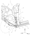
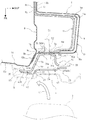
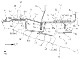
本発明の第1実施形態について説明する。図1および図2に示すように、本実施形態に係る車両前部構造1は、自動車である車両2におけるフロントタイヤ3の車体後方に位置する車体下部の構造である。なお、図2は、車両2の前部構造を示す水平断面図であり、図1におけるA−A位置(図4におけるA´−A´位置に対応)の断面図に相当する。
[First Embodiment]
A first embodiment of the present invention will be described. As shown in FIGS. 1 and 2, the vehicle front structure 1 according to the present embodiment is a structure at the lower part of the vehicle body that is located behind the front tire 3 in a vehicle 2 that is an automobile. 2 is a horizontal sectional view showing the front structure of the vehicle 2, and corresponds to a sectional view taken along the line AA in FIG. 1 (corresponding to the position A′-A ′ in FIG. 4).

車両前部構造1は、車両2において左右一対として構成されるロッカ4およびフロントピラー5を備える。ロッカ4およびフロントピラー5は、いずれも金属製の部材により構成される。   The vehicle front structure 1 includes a rocker 4 and a front pillar 5 configured as a pair of left and right in the vehicle 2. Both the rocker 4 and the front pillar 5 are made of metal members.

ロッカ4は、車両2の車体下部の車幅方向の両外側に車体前後方向を長手方向として配設されている。ロッカ4は、ロッカ4の車幅方向内側の部分を構成するロッカインナパネル(図示略)と、ロッカ4の車幅方向外側の部分を構成するロッカアウタパネル7とを有する。   The rocker 4 is disposed on both outer sides in the vehicle width direction at the lower portion of the vehicle body of the vehicle 2 with the vehicle body longitudinal direction as the longitudinal direction. The rocker 4 includes a rocker inner panel (not shown) that forms a portion of the rocker 4 on the inner side in the vehicle width direction, and a rocker outer panel 7 that forms a portion of the rocker 4 on the outer side in the vehicle width direction.

ロッカインナパネルは、ロッカ4の延設方向に対する横断面(鉛直断面)形状が略ハット形状となるように構成されており、その横断面形状の開口側が車幅方向外側を向くように設けられている。ロッカアウタパネル7は、図示では省略するが、ロッカ4の延設方向に対する横断面形状が略ハット形状となるように構成されており、その横断面形状の開口側が車幅方向内側を向くように設けられている。   The rocker inner panel is configured such that the cross section (vertical cross section) shape with respect to the extending direction of the rocker 4 is a substantially hat shape, and the opening side of the cross section shape is provided so as to face the outside in the vehicle width direction. Yes. Although not shown in the drawing, the rocker outer panel 7 is configured so that the cross-sectional shape with respect to the extending direction of the rocker 4 is a substantially hat shape, and the opening side of the cross-sectional shape is provided so as to face the inner side in the vehicle width direction. It has been.

このように横断面形状における開口側を互いに対向させた態様で設けられるロッカインナパネルおよびロッカアウタパネル7は、横断面形状である略ハット形状の鍔部分に相当するフランジ部同士がスポット溶接等によって互いに固定されることで、横断面において閉断面形状をなす中空状のフレーム部分を構成する。なお、中空状のロッカ4内には、ロッカ4を構成する部材とともに適宜閉断面構造をなす補強部材であるロッカリインフォースメントが車体前後方向に沿って設けられている。   As described above, the rocker inner panel and the rocker outer panel 7 provided in such a manner that the opening sides in the cross-sectional shape are opposed to each other, the flange portions corresponding to the substantially hat-shaped flange portions having a cross-sectional shape are mutually connected by spot welding or the like. By being fixed, a hollow frame portion having a closed cross-sectional shape in the cross section is formed. In the hollow rocker 4, rocker reinforcement that is a reinforcing member having a closed cross-sectional structure as appropriate together with the members constituting the rocker 4 is provided along the longitudinal direction of the vehicle body.

フロントピラー5は、ロッカ4の車体前方側の端部から車体上方へ向けて延設されている。すなわち、フロントピラー5は、車両2における前側のドアの開口部とフロントガラスとの間にて上下方向に延設され、フロントピラー5の下端部から、車体の後方へ向けてロッカ4が延設される。フロントピラー5とロッカ4とがなす略「L」字状の内側がドアの開口部となる。フロントピラー5は、フロントピラー5の車幅方向内側の部分を構成するフロントピラーインナパネル8と、フロントピラー5の車幅方向外側の部分を構成するフロントピラーアウタパネル9と、フロントピラーアウタパネル9を外側から覆うように設けられるサイドメンバアウタパネル10とを有する。   The front pillar 5 extends from the end of the rocker 4 on the front side of the vehicle body toward the upper side of the vehicle body. That is, the front pillar 5 extends vertically between the opening of the front door of the vehicle 2 and the windshield, and the rocker 4 extends from the lower end of the front pillar 5 toward the rear of the vehicle body. Is done. The inside of the substantially “L” shape formed by the front pillar 5 and the rocker 4 is the opening of the door. The front pillar 5 includes a front pillar inner panel 8 constituting an inner portion of the front pillar 5 in the vehicle width direction, a front pillar outer panel 9 constituting an outer portion of the front pillar 5 in the vehicle width direction, and the front pillar outer panel 9 outside. Side member outer panel 10 provided so as to cover from.

図2に示すように、フロントピラーインナパネル8は、フロントピラー5の延設方向に対する横断面(水平断面)形状が所定の凹凸形状をなしながら全体として略直線状となるように構成された部分を有し、その横断面形状の延設方向が車体前後方向に沿うように設けられている。また、フロントピラーアウタパネル9は、フロントピラー5の延設方向に対する横断面形状が略「コ」字状ないし略「U」字状となるように構成されており、その横断面形状の開口側が車幅方向内側を向くように設けられている。また、サイドメンバアウタパネル10は、フロントピラー5の延設方向に対する横断面形状が略ハット形状となるように構成されており、その横断面形状の開口側が車幅方向内側を向くように、つまり横断面形状の凸側が車幅方向外側を向くように設けられている。   As shown in FIG. 2, the front pillar inner panel 8 is configured such that the cross section (horizontal section) shape with respect to the extending direction of the front pillar 5 is substantially linear as a whole while forming a predetermined uneven shape. And the extending direction of the cross-sectional shape thereof is provided along the longitudinal direction of the vehicle body. Further, the front pillar outer panel 9 is configured such that the cross-sectional shape with respect to the extending direction of the front pillar 5 is substantially “U” or “U”, and the opening side of the cross-sectional shape is the vehicle side. It is provided so as to face the inner side in the width direction. Further, the side member outer panel 10 is configured such that the cross-sectional shape with respect to the extending direction of the front pillar 5 is substantially a hat shape, and the opening side of the cross-sectional shape faces the inner side in the vehicle width direction, that is, the crossing The surface-shaped convex side is provided so as to face the outside in the vehicle width direction.

フロントピラーアウタパネル9は、横断面形状において、サイドメンバアウタパネル10の凸形状に沿うように、サイドメンバアウタパネル10の内側に設けられている。そして、フロントピラーインナパネル8、フロントピラーアウタパネル9、およびサイドメンバアウタパネル10は、横断面形状におけるフロントピラーアウタパネル9およびサイドメンバアウタパネル10の開口側をフロントピラーインナパネル8が塞ぐような態様で設けられている。   The front pillar outer panel 9 is provided inside the side member outer panel 10 so as to follow the convex shape of the side member outer panel 10 in the cross-sectional shape. The front pillar inner panel 8, the front pillar outer panel 9, and the side member outer panel 10 are provided in such a manner that the front pillar inner panel 8 closes the opening side of the front pillar outer panel 9 and the side member outer panel 10 in the cross-sectional shape. ing.

フロントピラーインナパネル8は、横断面形状においてサイドメンバアウタパネル10の開口側を塞ぐ車体前後方向に沿う略直線状の部分の前後の端部を、接合縁部8b,8cとする。フロントピラーアウタパネル9は、その横断面形状において車幅方向内側を開口側とする「コ」字状ないし「U」字状の本体部9aの車体後方側の縁部から延出する車体前後方向に沿う部分をフランジ部9cとする。サイドメンバアウタパネル10は、その横断面形状において車幅方向内側を開口側とする「コ」字状ないし「U」字状の本体部10aの車体前後方向の両縁部から延出する部分であって略ハット形状の鍔部分に相当する部分を前後のフランジ部10b,10cとする。   In the front pillar inner panel 8, front and rear end portions of a substantially linear portion along the vehicle body front-rear direction that closes the opening side of the side member outer panel 10 in the cross-sectional shape are referred to as joining edge portions 8 b and 8 c. The front pillar outer panel 9 has a transverse cross-sectional shape that extends in the longitudinal direction of the vehicle body extending from the rear side edge of the body portion 9a of the "U" shape or "U" shape with the inner side in the vehicle width direction as the opening side. A portion along the line is referred to as a flange portion 9c. The side member outer panel 10 is a portion that extends from both edges in the longitudinal direction of the vehicle body of a “U” -shaped or “U” -shaped main body portion 10a whose inner side in the vehicle width direction is the opening side in the cross-sectional shape thereof. The portions corresponding to the substantially hat-shaped flange portions are the front and rear flange portions 10b and 10c.

そして、フロントピラーインナパネル8の車体後方側の接合縁部8cと、フロントピラーアウタパネル9およびサイドメンバアウタパネル10それぞれの車体後方側のフランジ部9c,10cとが、互いに重なり合った状態で、スポット溶接等によって互いに固定される。また、フロントピラーインナパネル8の車体前方側の接合縁部8bと、サイドメンバアウタパネル10の車体前方側のフランジ部10bとが、互いに重なり合った状態で、スポット溶接等によって互いに固定される。このようにして、横断面において閉断面形状をなす中空状のフレーム部分が構成される。   Further, spot welding or the like in a state where the joint edge portion 8c on the vehicle body rear side of the front pillar inner panel 8 and the flange portions 9c and 10c on the vehicle body rear side of the front pillar outer panel 9 and the side member outer panel 10 overlap each other. Fixed to each other. Further, the joint edge portion 8b on the vehicle body front side of the front pillar inner panel 8 and the flange portion 10b on the vehicle body front side of the side member outer panel 10 are fixed to each other by spot welding or the like in a state where they overlap each other. In this way, a hollow frame portion having a closed cross-sectional shape in the cross section is formed.

また、中空状のフロントピラー5内には、フロントピラー5を補強する部材であるフロントピラーリインフォースメント11が設けられている。図2に示すように、フロントピラーリインフォースメント11は、横断面形状において、フロントピラーアウタパネル9の凸形状に沿うように、フロントピラーアウタパネル9の内側に設けられている。   A front pillar reinforcement 11, which is a member that reinforces the front pillar 5, is provided in the hollow front pillar 5. As shown in FIG. 2, the front pillar reinforcement 11 is provided inside the front pillar outer panel 9 so as to follow the convex shape of the front pillar outer panel 9 in the cross-sectional shape.

すなわち、フロントピラーリインフォースメント11は、フロントピラー5の延設方向に対する横断面形状が略「コ」字状ないし略「U」字状となるように構成されており、その横断面形状の開口側が車幅方向内側を向くように設けられている。また、フロントピラーリインフォースメント11は、その横断面形状において「コ」字状ないし「U」字状の本体部11aの車体後方側の縁部から延出する車体前後方向に沿う部分をフランジ部11cとする。そして、フロントピラーリインフォースメント11は、上述のとおり接合縁部8cおよびフランジ部9c,10cの接合部分において、フランジ部11cを、接合縁部8cとフランジ部9cとの間に介装させた状態で、フロントピラーインナパネル8、フロントピラーアウタパネル9、およびサイドメンバアウタパネル10とともに接合される。   That is, the front pillar reinforcement 11 is configured such that the cross-sectional shape with respect to the extending direction of the front pillar 5 is a substantially “U” shape or a substantially “U” shape, and the opening side of the cross-sectional shape is It is provided so as to face the inside in the vehicle width direction. Further, the front pillar reinforcement 11 has a flange portion 11c that extends in the vehicle longitudinal direction extending from the rear edge of the body portion 11a of the "U" shape or "U" shape in the cross-sectional shape. And The front pillar reinforcement 11 is in a state where the flange portion 11c is interposed between the joint edge portion 8c and the flange portion 9c at the joint portion of the joint edge portion 8c and the flange portions 9c and 10c as described above. The front pillar inner panel 8, the front pillar outer panel 9, and the side member outer panel 10 are joined together.

以上のように複数の部材により構成されるロッカ4およびフロントピラー5は、互いに一体的に設けられて車両2の車体の骨格構造(以下「車体骨格構造」という。)の一部を構成する。つまり、上述のとおりロッカ4およびフロントピラー5のそれぞれを構成する複数の部材は、車両2の車体骨格部材となる。   As described above, the rocker 4 and the front pillar 5 constituted by a plurality of members are provided integrally with each other and constitute a part of the skeleton structure of the vehicle body of the vehicle 2 (hereinafter referred to as “vehicle skeleton structure”). That is, as described above, the plurality of members constituting each of the rocker 4 and the front pillar 5 are the vehicle body skeleton members of the vehicle 2.

車両2の全体をなす車体は、主に、車体骨格構造をなすロッカ4およびフロントピラー5等の金属製の車体フレーム、車体骨格構造の外側に設けられる外被部分を構成するボンネット等の金属製の車体パネル、樹脂製または金属製のバンパ等の外装部品等により構成される。例えば、車両前部構造1の車幅方向両外側には、車体の外被部分を構成する金属製の車体パネルとして、フロントフェンダパネル12が設けられている(図1参照)。   The vehicle body constituting the entire vehicle 2 is mainly made of a metal body frame such as a rocker 4 and a front pillar 5 that form a body frame structure, and a metal such as a bonnet that forms an outer cover portion provided outside the body frame structure. Vehicle body panels, exterior parts such as resin or metal bumpers, and the like. For example, a front fender panel 12 is provided on both outer sides in the vehicle width direction of the vehicle front structure 1 as a metal vehicle body panel that constitutes a jacket portion of the vehicle body (see FIG. 1).

また、車両2において左右略対称に構成される左右のロッカ4およびフロントピラー5の間であってロッカ4の車体前方側には、ダッシュパネル13が設けられている。ダッシュパネル13は、車両2が備えるエンジン等が収納されるエンジンルームとその車体後方に位置する運転席等が設けられる車室(車内空間)とを区画する比較的板厚の薄い板状の部材である。本実施形態の車両前部構造1において、ダッシュパネル13は、車幅方向の両側のロッカ4およびフロントピラー5の間に設けられ、車両2の車室の前側に位置する薄板部に相当する。なお、ダッシュパネル13の板厚は例えば1mm程度である。   In addition, a dash panel 13 is provided between the left and right rockers 4 and the front pillar 5 that are substantially symmetrical in the vehicle 2 and on the vehicle body front side of the rocker 4. The dash panel 13 is a plate-like member having a relatively thin plate thickness that partitions an engine room in which an engine or the like included in the vehicle 2 is housed and a passenger compartment (interior space) in which a driver's seat or the like located behind the vehicle body is provided. It is. In the vehicle front portion structure 1 of the present embodiment, the dash panel 13 is provided between the rocker 4 and the front pillar 5 on both sides in the vehicle width direction, and corresponds to a thin plate portion positioned on the front side of the vehicle compartment of the vehicle 2. The plate thickness of the dash panel 13 is about 1 mm, for example.

ダッシュパネル13は、車幅方向に延在する略平板状のダッシュパネル本体部13aと、ダッシュパネル本体部13aの車幅方向外側端部(両端部)に設けられたサイドフランジ部13bとを有する。サイドフランジ部13bは、ダッシュパネル本体部13aに対して車体後方側へ折れ曲がるようにダッシュパネル本体部13aと一体に形成されている。   The dash panel 13 has a substantially flat dash panel main body portion 13a extending in the vehicle width direction, and side flange portions 13b provided at the outer end portions (both ends) of the dash panel main body portion 13a in the vehicle width direction. . The side flange portion 13b is formed integrally with the dash panel main body portion 13a so as to bend toward the rear side of the vehicle body with respect to the dash panel main body portion 13a.

ダッシュパネル13は、そのサイドフランジ部13bの部分が、フロントピラー5の車体前方側のフロントピラーインナパネル8の接合縁部8bと、サイドメンバアウタパネル10のフランジ部10bとの接合部分に対して車幅方向内側から重ねられてスポット溶接等によって接合されることで、フロントピラー5に固定されている。つまり、ダッシュパネル13のサイドフランジ部13bの接合部分においては、車幅方向内側から順に、ダッシュパネル13のサイドフランジ部13b、フロントピラーインナパネル8の接合縁部8b、およびサイドメンバアウタパネル10のフランジ部10bが重ねられ、これら3つの板状部分がスポット溶接等により固定されている(図2参照)。   In the dash panel 13, the side flange portion 13 b of the dash panel 13 is mounted on the front edge of the front pillar inner panel 8 on the front side of the front pillar 5 and the flange portion 10 b of the side member outer panel 10. It is fixed to the front pillar 5 by being overlapped from the inner side in the width direction and joined by spot welding or the like. That is, at the joint portion of the side flange portion 13b of the dash panel 13, the side flange portion 13b of the dash panel 13, the joint edge portion 8b of the front pillar inner panel 8, and the flange of the side member outer panel 10 are sequentially arranged from the inner side in the vehicle width direction. The portions 10b are overlapped, and these three plate-like portions are fixed by spot welding or the like (see FIG. 2).

また、車両2は、車体骨格構造を構成する部材として、フロントサイドメンバ14およびトルクボックス15を備える。   The vehicle 2 includes a front side member 14 and a torque box 15 as members constituting the vehicle body skeleton structure.

フロントサイドメンバ14は、車両2において左右一対設けられており、長手方向を車体前後方向に沿わせて、車幅方向に並列に配設されている。フロントサイドメンバ14は、車体骨格構造においてダッシュパネル13の下側に位置し、ダッシュパネル13の車体後方側から車体前方側へかけて徐々に上り傾斜する斜面状の形状部分に沿うように設けられている。フロントサイドメンバ14は、その延設方向に対する横断面形状が略ハット形状となるように構成されており、その横断面形状の開口側を車体上方へ向けて設けられ、ダッシュパネル13の一部とともに閉断面構造をなす。   A pair of left and right front side members 14 are provided in the vehicle 2, and are arranged in parallel in the vehicle width direction with the longitudinal direction being along the longitudinal direction of the vehicle body. The front side member 14 is located on the lower side of the dash panel 13 in the vehicle body skeleton structure, and is provided along a slope-shaped portion that gradually inclines from the rear side of the dash panel 13 toward the front side of the vehicle body. ing. The front side member 14 is configured so that the cross-sectional shape with respect to the extending direction is substantially a hat shape. The front side member 14 is provided with the opening side of the cross-sectional shape facing upward of the vehicle body, together with a part of the dash panel 13. It has a closed cross-sectional structure.

トルクボックス15は、フロントサイドメンバ14の車幅方向外側に設けられ、ダッシュパネル13の車室外側において、フロントサイドメンバ14とロッカ4とを互いに連結する。トルクボックス15は、車体骨格構造を構成する他の部材とともに閉空間を形成する部材であり、複数の板状の部分により全体として凹形状をなす。トルクボックス15の側壁部分は、フロントサイドメンバ14の車幅方向外側の壁面に固定され、トルクボックス15の下側部分は、車体骨格構造を構成するフロアパネル(図示略)に固定されている。なお、トルクボックス15の内部には、トルクボックス15を構成する部材とともに適宜閉断面構造をなす補強部材であるトルクボックスリインフォースメント18が設けられている(図7参照)。   The torque box 15 is provided outside the front side member 14 in the vehicle width direction, and connects the front side member 14 and the rocker 4 to each other outside the passenger compartment of the dash panel 13. The torque box 15 is a member that forms a closed space together with other members constituting the vehicle body skeleton structure, and has a concave shape as a whole by a plurality of plate-like portions. A side wall portion of the torque box 15 is fixed to a wall surface on the outer side in the vehicle width direction of the front side member 14, and a lower side portion of the torque box 15 is fixed to a floor panel (not shown) constituting the vehicle body skeleton structure. In addition, a torque box reinforcement 18 which is a reinforcing member having a closed cross-sectional structure as appropriate together with members constituting the torque box 15 is provided inside the torque box 15 (see FIG. 7).

また、トルクボックス15の車幅方向外側の部分は、ロッカ4およびフロントピラー5の構成部材に固定される。具体的には次のとおりである。図6に示すように、トルクボックス15は、その車幅方向外側端部(両端部)に、トルクボックス本体部15aに対して車体前方側へ折れ曲がるように形成されたサイドフランジ部15bを有する。一方、上述したように、フロントピラー5を構成するフロントピラーインナパネル8は、車体前方側の端部に接合縁部8bを有する。そして、トルクボックス15のサイドフランジ部15bと、フロントピラーインナパネル8の接合縁部8bとが、互いに重なり合った状態で、スポット溶接等によって互いに固定される。なお、図6は、車両2の前部構造を示す水平断面図であり、ガセット部材20(ガセットリアパネル30)との関係において、図4におけるB−B位置の断面図に相当する。   Further, the outer portion of the torque box 15 in the vehicle width direction is fixed to the constituent members of the rocker 4 and the front pillar 5. Specifically, it is as follows. As shown in FIG. 6, the torque box 15 has side flange portions 15b formed at the vehicle width direction outer side end portions (both end portions) so as to be bent toward the vehicle body front side with respect to the torque box main body portion 15a. On the other hand, as described above, the front pillar inner panel 8 constituting the front pillar 5 has the joint edge portion 8b at the end on the vehicle body front side. And the side flange part 15b of the torque box 15 and the joining edge part 8b of the front pillar inner panel 8 are mutually fixed by spot welding etc. in the state which mutually overlapped. 6 is a horizontal cross-sectional view showing the front structure of the vehicle 2, and corresponds to a cross-sectional view taken along the line BB in FIG. 4 in relation to the gusset member 20 (the gusset rear panel 30).

さらに、図6に示すように、ロッカ4を構成するロッカアウタパネル7は、車体前方側の端部において、車幅方向外側の側壁部7aに対して車幅方向内側へ折れ曲がるように形成された前壁部7cと、前壁部7cに対して車体前方側へ折れ曲がるように形成された前フランジ部7bとを有する。前フランジ部7bは、サイドフランジ部15bと接合縁部8bとの接合部分に対して、車幅方向外側となる接合縁部8b側から重なり、スポット溶接等によって互いに固定される。つまり、トルクボックス15のロッカ4に対する接合部分においては、車幅方向内側から順に、トルクボックス15のサイドフランジ部15b、フロントピラーインナパネル8の接合縁部8b、およびロッカアウタパネル7の前フランジ部7bが重ねられ、これら3つの板状部分がスポット溶接等により固定されている。以上のようにして、トルクボックス15の車幅方向外側の部分は、ロッカ4に固定されている。   Further, as shown in FIG. 6, the rocker outer panel 7 constituting the rocker 4 is formed so as to be bent inward in the vehicle width direction with respect to the side wall portion 7a on the vehicle width direction outer side at the end on the vehicle body front side. It has the wall part 7c and the front flange part 7b formed so that it might bend to the vehicle body front side with respect to the front wall part 7c. The front flange portion 7b overlaps with the joint portion between the side flange portion 15b and the joint edge portion 8b from the joint edge portion 8b side which is the outer side in the vehicle width direction, and is fixed to each other by spot welding or the like. That is, at the joint portion of the torque box 15 to the rocker 4, the side flange portion 15 b of the torque box 15, the joint edge portion 8 b of the front pillar inner panel 8, and the front flange portion 7 b of the rocker outer panel 7 in order from the inner side in the vehicle width direction. These three plate-like portions are fixed by spot welding or the like. As described above, the outer portion of the torque box 15 in the vehicle width direction is fixed to the rocker 4.

また、トルクボックス15の車体上方側の部分は、ダッシュパネル13に固定される。具体的には、図7に示すように、トルクボックス15は、その車体上方側の部分に、車体後方側から車体前方側へかけて徐々に上り傾斜する斜面部15cを有する。斜面部15cは、ダッシュパネル13がダッシュパネル本体部13aにおいて車体下方側の端部に有する斜面部13cの傾斜に沿うように設けられている。そして、トルクボックス15は、その斜面部15cの部分が、ダッシュパネル13の斜面部13cに対して車体下方側(車体前方側)から重ねられてスポット溶接等によって接合されることで、ダッシュパネル13に固定されている。なお、図7は、車両2の前部構造を示す鉛直断面図であり、ガセット部材20(ガセットリアパネル30)との関係において、図4におけるC−C位置の断面図に相当する。   A portion of the torque box 15 on the vehicle body upper side is fixed to the dash panel 13. Specifically, as shown in FIG. 7, the torque box 15 has a slope portion 15 c that gradually inclines from the rear side of the vehicle body to the front side of the vehicle body at a portion on the upper side of the vehicle body. The slope part 15c is provided so that the dash panel 13 may follow the slope of the slope part 13c that the dash panel body part 13a has at the end on the vehicle body lower side. The torque box 15 has a slope portion 15c overlapped with the slope portion 13c of the dash panel 13 from the vehicle body lower side (vehicle body front side) and joined by spot welding or the like. It is fixed to. 7 is a vertical cross-sectional view showing the front structure of the vehicle 2, and corresponds to a cross-sectional view taken along the line CC in FIG. 4 in relation to the gusset member 20 (gusset rear panel 30).

以上のような車両2の前部構造において、左右両側のロッカ4の車体前方に、タイヤハウスが構成され、このタイヤハウス内に、フロントタイヤ3が配置される。フロントタイヤ3が配置されるタイヤハウスは、一般に合成樹脂材料からなる半円弧状の薄板部材であるフェンダライナ16等により構成されている。   In the front structure of the vehicle 2 as described above, a tire house is configured in front of the body of the rocker 4 on both the left and right sides, and the front tire 3 is disposed in the tire house. The tire house in which the front tire 3 is arranged is configured by a fender liner 16 or the like, which is a semicircular arc thin plate member generally made of a synthetic resin material.

以上のような構成を備える車両2の前部構造に関し、車両2のオフセット衝突時、特に微小ラップ衝突時において、衝突した側のフロントタイヤ3は、車体側に対する連結構造等により動きが規制される関係上、ロッカ4の前方を通る弧を描くような軌跡をたどって車両の内側に転舵しながら(内回りしながら)後退する(図2、矢印L1参照)。このように内回りしながら後退するフロントタイヤ3は、左右のロッカ4およびフロントピラー5間のダッシュパネル13に向かうことになり、その挙動によってはダッシュパネル13に衝撃を与えるような軌跡をたどり、ダッシュパネル13の変形量を大きくし、車室のスペースを減少させる原因となり得る。   With regard to the front structure of the vehicle 2 having the above-described configuration, the front tire 3 on the collision side is restricted in movement by the connection structure to the vehicle body side at the time of the offset collision of the vehicle 2, particularly at the time of a minute lap collision. In relation, it follows a trajectory that draws an arc passing in front of the rocker 4 and moves backward (turning inward) while turning inside the vehicle (see arrow L1 in FIG. 2). The front tire 3 retreating while turning inward is directed to the dash panel 13 between the left and right rockers 4 and the front pillar 5. Depending on the behavior, the front tire 3 follows a trajectory that gives an impact to the dash panel 13. This can increase the amount of deformation of the panel 13 and reduce the space in the passenger compartment.

そこで、本実施形態の車両前部構造1は、車両2のオフセット衝突時等の車両前部衝突時におけるフロントタイヤ3の後退に対処するため、フロントピラー5の車体前方側に設けられるガセット部材20を備える。ガセット部材20は、フロントピラー5の車体前方側の下部の略全体を覆うように設けられてロッカ4およびフロントピラー5を含む車体骨格構造を補強する補強部材である。   Therefore, the vehicle front structure 1 according to the present embodiment is provided with a gusset member 20 provided on the front side of the vehicle body of the front pillar 5 in order to cope with the backward movement of the front tire 3 at the time of a vehicle front collision such as an offset collision of the vehicle 2. Is provided. The gusset member 20 is a reinforcing member that is provided so as to cover substantially the entire lower portion of the front pillar 5 on the front side of the vehicle body and reinforces the vehicle body skeleton structure including the rocker 4 and the front pillar 5.

図1および図3に示すように、ガセット部材20は、全体として比較的幅狭の略矩形板状の外形をなすように構成されており、その両側の板面を車体前後方向に向けるとともに、長手方向を車体上下方向に沿わせた姿勢で、フロントピラー5の下部の車体前方側にあてがわれた状態で設けられる。つまり、図2に示すように、ガセット部材20は、フロントタイヤ3のタイヤハウスの車体後方において、タイヤハウスを構成するフェンダライナ16とフロントピラー5との間に位置し、フェンダライナ16に車体前方側から覆われた状態となる。   As shown in FIGS. 1 and 3, the gusset member 20 is configured to have a generally rectangular plate-like outer shape having a relatively narrow width as a whole, with the plate surfaces on both sides thereof directed in the longitudinal direction of the vehicle body, It is provided in a state where the longitudinal direction is aligned with the vertical direction of the vehicle body and applied to the front side of the vehicle body at the lower part of the front pillar 5. That is, as shown in FIG. 2, the gusset member 20 is positioned between the fender liner 16 and the front pillar 5 constituting the tire house on the rear side of the tire house of the front tire 3, and on the fender liner 16 on the front side of the vehicle body. It will be covered from the side.

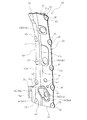
図3、図4、および図5に示すように、ガセット部材20は、ガセット部材20の車体後方側の部分を構成する後側部材であるガセットリアパネル30と、ガセット部材20の車体前方側の部分を構成する前側部材であるガセットフロントパネル40とにより構成されている。すなわち、ガセット部材20は、車体に設けられた状態において、ガセットリアパネル30を車体後方側に位置させるとともに、ガセットフロントパネル40を車体前方側に位置させる。   As shown in FIGS. 3, 4, and 5, the gusset member 20 includes a gusset rear panel 30, which is a rear member that constitutes a vehicle rear side portion of the gusset member 20, and a vehicle body front portion of the gusset member 20. It is comprised with the gusset front panel 40 which is the front side member which comprises. That is, the gusset member 20 places the gusset rear panel 30 on the vehicle body rear side and the gusset front panel 40 on the vehicle body front side in a state where it is provided on the vehicle body.

ガセットリアパネル30およびガセットフロントパネル40は、互いに略同じ略矩形板状の外形をなす板状の部材であり、互いに重ねられ互いに固定された状態でガセット部材20を構成する。ガセットリアパネル30およびガセットフロントパネル40は、互いに略同じ外形を合わせた状態(略一致させた状態)で重ね合わさり、互いに固定される。したがって、車体に設けられた状態のガセット部材20を車体前方から視た場合、外観に現れる大部分(略全体)をガセットフロントパネル40が占めることになる。   The gusset rear panel 30 and the gusset front panel 40 are plate-like members having substantially the same rectangular plate-like outer shape, and constitute the gusset member 20 in a state where they are overlapped and fixed to each other. The gusset rear panel 30 and the gusset front panel 40 are overlapped and fixed to each other in a state in which substantially the same outer shape is matched (substantially matched). Therefore, when the gusset member 20 in the state provided in the vehicle body is viewed from the front of the vehicle body, the gusset front panel 40 occupies most (substantially the whole) appearing in the appearance.

ガセットリアパネル30およびガセットフロントパネル40は、それぞれ所定の板厚(例えば、2mm程度)の鋼板が所定の加工を受けて所定の形状に形成された部材である。つまり、本実施形態のガセット部材20は、全体として鉄鋼材料により構成された鉄製の部材である。本実施形態では、ガセットリアパネル30は、ガセットフロントパネル40よりも厚い鋼板により構成されている。ただし、両パネルの板厚については、互いに同一であってもよく、ガセットフロントパネル40の方がガセットリアパネル30よりも厚くてもよい。   Each of the gusset rear panel 30 and the gusset front panel 40 is a member in which a steel plate having a predetermined thickness (for example, about 2 mm) is subjected to predetermined processing and formed into a predetermined shape. That is, the gusset member 20 of the present embodiment is an iron member made of a steel material as a whole. In the present embodiment, the gusset rear panel 30 is made of a steel plate that is thicker than the gusset front panel 40. However, the thicknesses of both panels may be the same, and the gusset front panel 40 may be thicker than the gusset rear panel 30.

ガセット部材20は、互いに一体的に設けられるロッカ4およびフロントピラー5を含む車体骨格構造に固定された状態で設けられる。本実施形態では、互いに固定されたガセットリアパネル30およびガセットフロントパネル40により構成されるガセット部材20は、ガセットリアパネル30の部分を車体骨格構造に固定させることで、車体骨格構造に固定される。   The gusset member 20 is provided in a state of being fixed to a vehicle body skeleton structure including the rocker 4 and the front pillar 5 provided integrally with each other. In the present embodiment, the gusset member 20 constituted by the gusset rear panel 30 and the gusset front panel 40 fixed to each other is fixed to the vehicle body skeleton structure by fixing a portion of the gusset rear panel 30 to the vehicle body skeleton structure.

また、ガセット部材20は、少なくともフロントタイヤ3と車体上下方向でオーバーラップする位置に設けられる。つまり、フロントタイヤ3の車体後方に位置するガセット部材20は、車体前方視で、車体上下方向について少なくとも一部に、フロントタイヤ3に対して車体前後方向に重なる部分を有するように設けられる。   The gusset member 20 is provided at a position that overlaps at least the front tire 3 in the vertical direction of the vehicle body. That is, the gusset member 20 located at the rear of the vehicle body of the front tire 3 is provided so as to have a portion that overlaps with the front tire 3 in the vehicle body front-rear direction at least partially in the vehicle body vertical direction.

このように、本実施形態に係るガセット部材20は、車体骨格構造に固定されるガセットリアパネル30と、ガセットリアパネル30に対して車体前方側に重なりガセットリアパネル30に固定されるガセットフロントパネル40とにより構成されている。なお、ガセットリアパネル30とガセットフロントパネル40との相互の接合構造、およびガセット部材20の車体骨格構造に対する固定構造については後述する。   As described above, the gusset member 20 according to the present embodiment includes the gusset rear panel 30 fixed to the vehicle body skeleton structure, and the gusset front panel 40 fixed to the gusset rear panel 30 so as to overlap the gusset rear panel 30 on the vehicle body front side. It is configured. The mutual joint structure between the gusset rear panel 30 and the gusset front panel 40 and the fixing structure of the gusset member 20 to the vehicle body skeleton structure will be described later.

ガセット部材20は、フロントピラー5の車体前方側の下部の少なくとも一部を覆うように設けられる部材であって、車体前方側に、車体上下方向に沿うとともに車幅方向外側の部分に対して車幅方向内側の部分を相対的に車体前方側に位置させる段差部21を有する。段差部21は、ガセット部材20の車幅方向外側の本体部分の車幅方向内側の縁部に沿って設けられ、本体部分に対して車体前方側に立ち上がるとともに車幅方向外側を向く段差面22を形成する部分である。   The gusset member 20 is a member provided so as to cover at least a part of the lower part of the front pillar 5 on the front side of the vehicle body. A step portion 21 is provided for positioning the inner portion in the width direction relatively to the front side of the vehicle body. The stepped portion 21 is provided along the edge in the vehicle width direction inside of the main body portion on the outer side in the vehicle width direction of the gusset member 20, and rises in the vehicle body front side with respect to the main body portion and faces the outer side in the vehicle width direction. It is a part that forms.

以下、ガセット部材20について詳細に説明する。なお、以下の説明では、ガセット部材20において、ガセットリアパネル30側を背面側、ガセットフロントパネル40側を正面側とする。また、車幅方向に対応するガセット部材20の幅方向、つまりガセットリアパネル30およびガセットフロントパネル40の幅方向を「ガセット幅方向」とし、車体上下方向に対応するガセット部材20の長手方向、つまりガセットリアパネル30およびガセットフロントパネル40の長手方向を「ガセット長手方向」とする。   Hereinafter, the gusset member 20 will be described in detail. In the following description, in the gusset member 20, the gusset rear panel 30 side is the back side, and the gusset front panel 40 side is the front side. Further, the width direction of the gusset member 20 corresponding to the vehicle width direction, that is, the width direction of the gusset rear panel 30 and the gusset front panel 40 is defined as the “gusset width direction”, and the longitudinal direction of the gusset member 20 corresponding to the vehicle body vertical direction, that is, the gusset The longitudinal direction of the rear panel 30 and the gusset front panel 40 is referred to as a “gusset longitudinal direction”.

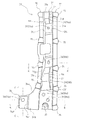
まず、ガセットリアパネル30について説明する。図2および図4に示すように、ガセットリアパネル30は、その大部分がガセット長手方向に対する横断面(水平断面)形状が略ハット形状となるように構成されている。ガセットリアパネル30は、その横断面形状の開口側を車体前方側(ガセットフロントパネル40側)に向けた状態で、つまり横断面形状の凸側を車体後方側(背面側)に向けた状態で設けられる。   First, the gusset rear panel 30 will be described. As shown in FIGS. 2 and 4, most of the gusset rear panel 30 is configured such that the cross section (horizontal section) shape with respect to the longitudinal direction of the gusset has a substantially hat shape. The gusset rear panel 30 is provided with the opening side of the cross-sectional shape facing the front side of the vehicle body (the gusset front panel 40 side), that is, with the convex side of the cross-sectional shape facing the rear side of the vehicle body (the back side). It is done.

ガセットリアパネル30は、略ハット形状の横断面形状をなす部分として、ガセット幅方向の中間部を構成するガセットリアパネル本体部31と、ガセットリアパネル本体部31に対してガセット幅方向の両側に設けられる内側フランジ部32および外側フランジ部33とを有する。ガセットリアパネル本体部31、内側フランジ部32、および外側フランジ部33は、ガセット長手方向の略全体にわたり、ガセット幅方向に並列的に設けられ、ガセットリアパネル30の略全体を構成する。   The gusset rear panel 30 includes a gusset rear panel main body 31 constituting an intermediate portion in the gusset width direction as a portion having a substantially hat-shaped cross section, and an inner side provided on both sides of the gusset rear panel main body 31 in the gusset width direction. A flange portion 32 and an outer flange portion 33 are provided. The gusset rear panel main body 31, the inner flange portion 32, and the outer flange portion 33 are provided in parallel in the gusset width direction over substantially the entire gusset longitudinal direction, and constitute substantially the entire gusset rear panel 30.

ガセットリアパネル本体部31は、横断面において正面側を開口側とする略「コ」字状ないし略「U」字状の形状をなす部分を有する。かかる部分は、ガセットリアパネル30の横断面形状において、突出側の端面部である後壁部31aと、後壁部31aの車幅方向外側において車体前方側に立ち上がる外側側壁部31bと、後壁部31aの車幅方向内側において車体前方側に立ち上がる内側側壁部31cとにより構成される。   The gusset rear panel main body 31 has a portion having a substantially “U” shape or a substantially “U” shape with the front side being the opening side in the cross section. Such portions include, in the cross-sectional shape of the gusset rear panel 30, a rear wall portion 31a that is an end surface portion on the protruding side, an outer side wall portion 31b that rises toward the front of the vehicle body on the outer side in the vehicle width direction of the rear wall portion 31a, and a rear wall portion. It is comprised by the inner side wall part 31c which stands to the vehicle body front side in the vehicle width direction inside of 31a.

後壁部31aは、車体前後方向に対して略垂直な板状の部分、つまり両側の板面を車体前後方向に向ける板状の部分であり、ガセット部材20の背面側の端面部を構成する。つまり、後壁部31aは、ガセット部材20の背面側の壁面部のガセット幅方向の中間部が部分的に車体後方側に突出した態様をなす部分となる。後壁部31aは、後述のように車体骨格構造に固定されるガセット部材20において、車体骨格構造に固定される部分に含まれる。   The rear wall portion 31a is a plate-like portion that is substantially perpendicular to the longitudinal direction of the vehicle body, that is, a plate-like portion that faces the plate surfaces on both sides in the longitudinal direction of the vehicle body, and constitutes an end surface portion on the back side of the gusset member 20. . That is, the rear wall portion 31a is a portion that forms an aspect in which an intermediate portion in the gusset width direction of the wall surface portion on the back surface side of the gusset member 20 partially protrudes toward the vehicle body rear side. The rear wall portion 31a is included in a portion fixed to the vehicle body skeleton structure in the gusset member 20 fixed to the vehicle body skeleton structure as described later.

外側側壁部31bは、横断面視において、後壁部31aの車幅方向外側の端部から車体前方側へ向けて折れ曲がるように形成された板状の部分である。外側側壁部31bの端部に、外側フランジ部33が繋がる。   The outer side wall portion 31b is a plate-like portion formed so as to be bent from the end portion on the outer side in the vehicle width direction of the rear wall portion 31a toward the front side of the vehicle body in a cross sectional view. The outer flange portion 33 is connected to the end portion of the outer side wall portion 31b.

内側側壁部31cは、横断面視において、後壁部31aの車幅方向内側の端部から車体前方側かつ車幅方向内側へ斜めに向けて折れ曲がるように形成された板状の部分である。内側側壁部31cは、後壁部31aに対して外側側壁部31bよりも車体前方側へと延設されている。内側側壁部31cの端部に、内側フランジ部32が繋がる。   The inner side wall portion 31c is a plate-like portion formed so as to be bent obliquely from the end of the rear wall portion 31a on the inner side in the vehicle width direction toward the front side of the vehicle body and the inner side in the vehicle width direction when viewed in cross section. The inner side wall portion 31c extends to the front side of the vehicle body with respect to the rear wall portion 31a rather than the outer side wall portion 31b. The inner flange portion 32 is connected to the end portion of the inner side wall portion 31c.

内側フランジ部32は、ガセットリアパネル本体部31の車幅方向内側の縁部、つまり後壁部31aに対する折曲部分である内側側壁部31cの縁部から延出する板状の部分であって、ガセットリアパネル30の略ハット形状の横断面形状における車幅方向内側の鍔部分に相当する。本実施形態では、内側フランジ部32は、車体前後方向に垂直な面に対して車幅方向外側から車幅方向内側にかけて車体後方側へわずかに傾斜するように傾斜状に設けられている。   The inner flange portion 32 is a plate-like portion extending from the inner edge of the gusset rear panel main body 31 in the vehicle width direction, that is, from the edge of the inner side wall 31c that is a bent portion with respect to the rear wall 31a. This corresponds to the flange portion on the inner side in the vehicle width direction in the substantially hat-shaped cross-sectional shape of the gusset rear panel 30. In the present embodiment, the inner flange portion 32 is provided so as to be inclined slightly toward the vehicle body rear side from the vehicle width direction outer side to the vehicle width direction inner side with respect to a plane perpendicular to the vehicle body longitudinal direction.

外側フランジ部33は、ガセットリアパネル本体部31の車幅方向外側の縁部、つまり後壁部31aに対する折曲部分である外側側壁部31bの縁部から延出する板状の部分であって、ガセットリアパネル30の略ハット形状の横断面形状における車幅方向外側の鍔部分に相当する。本実施形態では、外側フランジ部33は、車体前後方向に垂直な面に沿うように設けられている。   The outer flange portion 33 is a plate-like portion extending from the edge of the gusset rear panel main body 31 on the outer side in the vehicle width direction, that is, the edge of the outer side wall 31b that is a bent portion with respect to the rear wall 31a. This corresponds to the flange portion on the outer side in the vehicle width direction in the substantially hat-shaped cross-sectional shape of the gusset rear panel 30. In the present embodiment, the outer flange portion 33 is provided along a plane perpendicular to the longitudinal direction of the vehicle body.

内側フランジ部32および外側フランジ部33は、図4に示すように、ガセットリアパネル30の正面視(前面視)においてガセット長手方向を長手方向とする幅狭の略帯板状の部分である。そして、左右の内側フランジ部32および外側フランジ部33の間において、ガセットリアパネル本体部31により、車体後方側(背面側)を底側とする溝状の部分が構成される。   As shown in FIG. 4, the inner flange portion 32 and the outer flange portion 33 are narrow strip-shaped portions having a narrow gusset longitudinal direction as a longitudinal direction in a front view (front view) of the gusset rear panel 30. Between the left and right inner flange portions 32 and the outer flange portion 33, the gusset rear panel main body portion 31 forms a groove-like portion whose bottom side is the vehicle body rear side (back side).

また、ガセットリアパネル30は、車体下方側の端部に、車幅方向の内側に延出する下端延出部34を有する。下端延出部34は、ガセットリアパネル30の正面視において、ガセットリアパネル30の全長の約1/5の下端部が車幅方向の内側に向けてガセットリアパネル30の他の部分のガセット幅方向の寸法に対して2倍程度の寸法となるように突設されている。したがって、下端延出部34は、ガセットリアパネル30の下端部のガセット幅方向の寸法を部分的に2倍程度に増大させる。下端延出部34は、内側フランジ部32から車幅方向内側に延出された部分であり、ガセットリアパネル30の上側の部分に対して、上側から下側にかけて滑らかな曲線に沿ってガセットリアパネル30のガセット幅方向の寸法を車幅方向内側に徐々に広げる曲線形成部34aを経て設けられている。   The gusset rear panel 30 has a lower end extending portion 34 that extends inward in the vehicle width direction at an end portion on the vehicle body lower side. The lower end extending portion 34 is a dimension in the gusset width direction of the other portion of the gusset rear panel 30 with the lower end portion of about 1/5 of the total length of the gusset rear panel 30 facing inward in the vehicle width direction when the gusset rear panel 30 is viewed from the front. Projecting so as to have a size about twice as large as that. Therefore, the lower end extending portion 34 partially increases the size of the lower end portion of the gusset rear panel 30 in the gusset width direction by about twice. The lower end extending portion 34 is a portion extending inward in the vehicle width direction from the inner flange portion 32, and the gusset rear panel 30 along a smooth curve from the upper side to the lower side with respect to the upper portion of the gusset rear panel 30. Is provided through a curve forming portion 34a that gradually widens the dimension in the gusset width direction inward in the vehicle width direction.

ガセットリアパネル30全体としては、正面視において、車幅方向外側の縁部は、外側フランジ部33により、車体上下方向に沿うように略直線状に形成されている。これに対し、車幅方向内側の縁部は、内側フランジ部32により上側から曲線形成部34aにかけて徐々に車幅方向内側に広がり、曲線形成部34aを経て下端延出部34により急激に幅広となる。このように下端延出部34を有するガセットリアパネル30は、正面視で全体として略「L」字状ないし略長靴形状となるように構成されている。   As a whole of the gusset rear panel 30, an edge on the outer side in the vehicle width direction is formed in a substantially linear shape along the vertical direction of the vehicle body by the outer flange portion 33 in a front view. On the other hand, the inner edge in the vehicle width direction gradually spreads inward in the vehicle width direction from the upper side to the curve forming portion 34a by the inner flange portion 32, and suddenly widens by the lower end extending portion 34 through the curve forming portion 34a. Become. Thus, the gusset rear panel 30 having the lower end extending portion 34 is configured to have a substantially “L” shape or a substantially boots shape as a whole in a front view.

下端延出部34は、車体前後方向について屈曲する所定の屈曲形状を有する。具体的には、図6に示すように、下端延出部34は、平面断面視において、内側フランジ部32からの車幅方向内側へ向かう延設部分である延設壁部34bと、延設壁部34bの車幅方向内側の端部から車体後方側へ向けて折れ曲がるように形成された板状の部分である側壁部34cと、側壁部34cの車体後方側の端部から車幅方向内側へ向けて折れ曲がるように形成された板状の部分である端壁部34dとを有する。   The lower end extending portion 34 has a predetermined bent shape that bends in the longitudinal direction of the vehicle body. Specifically, as shown in FIG. 6, the lower end extending portion 34 includes an extending wall portion 34 b that is an extending portion from the inner flange portion 32 toward the inner side in the vehicle width direction in plan view, and an extended portion. A side wall 34c, which is a plate-like portion formed so as to bend toward the rear side of the vehicle body from the inner end in the vehicle width direction of the wall 34b, and an inner side in the vehicle width direction from the end of the side wall 34c on the rear side of the vehicle body And an end wall portion 34d which is a plate-like portion formed so as to be bent toward the end.

下端延出部34を構成する端壁部34dは、後述のように車体骨格構造に固定されるガセット部材20において、車体骨格構造に固定される部分に含まれる。本実施形態では、端壁部34dは、車体前後方向について、ガセットリアパネル本体部31の後壁部31aよりもわずかに車体後方側に位置する(図6参照)。   The end wall portion 34d constituting the lower end extending portion 34 is included in a portion fixed to the vehicle body skeleton structure in the gusset member 20 fixed to the vehicle body skeleton structure as described later. In the present embodiment, the end wall portion 34d is located slightly behind the vehicle body in the vehicle longitudinal direction with respect to the rear wall portion 31a of the gusset rear panel main body 31 (see FIG. 6).

次に、ガセットフロントパネル40について説明する。図2および図5に示すように、ガセットフロントパネル40は、ガセット部材20の車体前方側の部分を構成する部材であり、上述のとおりガセット部材20が車体前方側に有する段差部21を形成する部材である。   Next, the gusset front panel 40 will be described. As shown in FIGS. 2 and 5, the gusset front panel 40 is a member that constitutes a portion of the gusset member 20 on the vehicle body front side, and forms the step portion 21 that the gusset member 20 has on the vehicle body front side as described above. It is a member.

ガセットフロントパネル40は、横断面形状において車幅方向に沿う略直線状をなすように略平面状に構成されたガセットフロントパネル本体部41と、ガセットフロントパネル本体部41の車幅方向内側に設けられて段差部21を形成する段差形成部42とを有する。ガセットフロントパネル本体部41および段差形成部42は、ガセット長手方向の略全体にわたり、ガセット幅方向に並列的に設けられ、ガセットフロントパネル40の全体を構成する。   The gusset front panel 40 is provided on the inner side in the vehicle width direction of the gusset front panel main body 41 and the gusset front panel main body 41 configured in a substantially planar shape so as to form a substantially straight line along the vehicle width direction in the cross-sectional shape. And a step forming portion 42 that forms the step portion 21. The gusset front panel main body 41 and the step forming portion 42 are provided in parallel in the gusset width direction over substantially the entire gusset longitudinal direction, and constitute the entire gusset front panel 40.

ガセットフロントパネル本体部41は、略矩形板状の外形をなすガセットフロントパネル40において、ガセット幅方向について、車幅方向外側の半分以上(本実施形態では2/3〜3/4程度)の部分を構成する略矩形板状の部分である。つまり、ガセットフロントパネル本体部41は、段差形成部42に対して比較的幅広のガセット長手方向に沿う帯板状の部分である。   The gusset front panel main body 41 is a portion of the gusset front panel 40 having a substantially rectangular plate-like outer shape, which is a half or more (about 2/3 to 3/4 in the present embodiment) outside the vehicle width direction in the gusset width direction. Is a substantially rectangular plate-like portion. That is, the gusset front panel main body 41 is a band-plate-like portion along the longitudinal direction of the gusset that is relatively wide with respect to the step forming portion 42.

段差形成部42は、略矩形板状の外形をなすガセットフロントパネル40において、ガセット幅方向について、ガセットフロントパネル本体部41よりも車幅方向内側の部分を構成する略矩形板状の部分である。つまり、段差形成部42は、ガセットフロントパネル本体部41に対して比較的幅狭のガセット長手方向に沿う帯板状の部分である。   In the gusset front panel 40 having a substantially rectangular plate-shaped outer shape, the step forming portion 42 is a substantially rectangular plate-shaped portion that constitutes a portion on the inner side in the vehicle width direction than the gusset front panel main body portion 41 in the gusset width direction. . That is, the step forming portion 42 is a strip-like portion along the longitudinal direction of the gusset that is relatively narrow with respect to the gusset front panel main body 41.

段差形成部42は、ガセットフロントパネル本体部41に対して段差部21を形成する部分であり、段差部21による段差分、ガセットフロントパネル本体部41に対して車体前方側に大部分を位置させる。すなわち、段差形成部42は、ガセットフロントパネル本体部41に対して車体前方側に立ち上がるとともにガセットフロントパネル本体部41の車幅方向内側の縁部に沿う段差部21を形成する。   The step forming portion 42 is a portion that forms the step portion 21 with respect to the gusset front panel main body portion 41, and most of the step portion 21 is positioned on the front side of the vehicle body with respect to the gusset front panel main body portion 41. . That is, the step forming portion 42 rises toward the front of the vehicle body with respect to the gusset front panel main body 41 and forms the step 21 along the inner edge of the gusset front panel main body 41 in the vehicle width direction.

具体的には、図2に示すように、段差形成部42は、ガセットフロントパネル40の横断面形状において、段差面22を形成する段差面形成部42aと、段差面形成部42aから車幅方向内側に延設される内側フランジ部42bとを有する。段差面形成部42aは、ガセットフロントパネル本体部41の車幅方向内側の端部から車体前方側へ向けて折れ曲がるように形成された板状の部分である。内側フランジ部42bは、段差面形成部42aの車体前方側の端部から車幅方向内側へ向けて折れ曲がるように形成された板状の部分である。   Specifically, as shown in FIG. 2, the step forming portion 42 includes a step surface forming portion 42a that forms the step surface 22 and a vehicle width direction from the step surface forming portion 42a in the cross-sectional shape of the gusset front panel 40. And an inner flange portion 42b extending inward. The stepped surface forming portion 42a is a plate-like portion formed so as to be bent from the inner end in the vehicle width direction of the gusset front panel main body portion 41 toward the vehicle body front side. The inner flange portion 42b is a plate-like portion formed so as to be bent inward in the vehicle width direction from the end portion of the step surface forming portion 42a on the vehicle body front side.

すなわち、段差形成部42は、ガセットフロントパネル本体部41に対して車幅方向内側の縁部に沿って車体前方側に立ち上がる段差面形成部42aにより、ガセットフロントパネル40の車体前方側、つまりガセット部材20の正面側において、車幅方向外側を向く段差面22を形成する。本実施形態では、段差面形成部42aは、車体前方側かつ車幅方向内側へ斜めに向くように傾斜状に設けられている。このため、段差面形成部42aの車体前方側の面である段差面22は、段差面形成部42aの傾斜に沿って、車体前方側かつ車幅方向外側を向く面となっている。   That is, the step forming portion 42 is formed on the front side of the vehicle body of the gusset front panel 40, that is, the gusset by the step surface forming portion 42a that rises to the front side of the vehicle body along the inner edge in the vehicle width direction with respect to the gusset front panel body portion 41. On the front side of the member 20, a step surface 22 facing outward in the vehicle width direction is formed. In the present embodiment, the step surface forming portion 42a is provided in an inclined shape so as to be inclined obliquely toward the vehicle body front side and the vehicle width direction inner side. For this reason, the step surface 22 which is the surface on the vehicle body front side of the step surface forming portion 42a is a surface facing the vehicle body front side and the vehicle width direction outside along the inclination of the step surface forming portion 42a.

このようにガセットフロントパネル本体部41に対して段差部21を形成する段差形成部42は、段差部21による段差分、内側フランジ部42bをガセットフロントパネル本体部41に対して車体前方側に位置させる。言い換えると、内側フランジ部42bは、ガセットフロントパネル本体部41に対して段差面形成部42aを介して設けられることで、段差面形成部42aのガセットフロントパネル本体部41からの車体前方側への延出により、ガセットフロントパネル本体部41よりも車体前方側に位置する。   In this way, the step forming portion 42 that forms the step portion 21 with respect to the gusset front panel main body 41 is located on the vehicle body front side with respect to the gusset front panel main body 41 with respect to the step by the step portion 21. Let In other words, the inner flange portion 42b is provided to the gusset front panel main body 41 via the step surface forming portion 42a, so that the step surface forming portion 42a extends from the gusset front panel main body 41 to the front side of the vehicle body. Due to the extension, the gusset front panel main body 41 is located on the front side of the vehicle body.

ガセットフロントパネル40の正面視における上下方向を長手方向とする略矩形形状の外形は、ガセットリアパネル30の正面視における下端延出部34以外の部分の外形と略同じである。そして、ガセットリアパネル30とガセットフロントパネル40とは、互いに共通する正面視での略縦長矩形状の外形形状部分を互いに略一致させて重なり合った状態で接合される。したがって、ガセット部材20の正面視においては、ガセットフロントパネル40の背面側に位置するガセットリアパネル30のうち、下端延出部34の部分は、ガセットフロントパネル40により正面側から覆われることなく外部に露出した状態となる。   The outer shape of the substantially rectangular shape with the vertical direction in the front view of the gusset front panel 40 as the longitudinal direction is substantially the same as the outer shape of the portion other than the lower end extending portion 34 in the front view of the gusset rear panel 30. Then, the gusset rear panel 30 and the gusset front panel 40 are joined in a state where they overlap each other with their substantially vertical rectangular outer shape portions in front view that are common to each other being substantially coincident with each other. Therefore, in the front view of the gusset member 20, the portion of the lower end extending portion 34 of the gusset rear panel 30 located on the back side of the gusset front panel 40 is not covered from the front side by the gusset front panel 40. It will be exposed.

続いて、ガセットリアパネル30およびガセットフロントパネル40の相互の接合構造について説明する。ガセットリアパネル30およびガセットフロントパネル40は、複数箇所でスポット溶接されることにより、互いに接合されている。ガセットリアパネル30とガセットフロントパネル40との間においては、重なり合って互いに接触する部分が存在し、かかる部分がスポット溶接によって接合されることで、ガセットリアパネル30とガセットフロントパネル40とが全体として互いに固定され、一体的なガセット部材20が構成されている。   Subsequently, the mutual joining structure of the gusset rear panel 30 and the gusset front panel 40 will be described. The gusset rear panel 30 and the gusset front panel 40 are joined to each other by spot welding at a plurality of locations. Between the gusset rear panel 30 and the gusset front panel 40, there are portions that overlap and contact each other, and these portions are joined together by spot welding so that the gusset rear panel 30 and the gusset front panel 40 are fixed together as a whole. Thus, an integral gusset member 20 is configured.

ガセットリアパネル30およびガセットフロントパネル40は、横断面形状におけるガセットリアパネル30の略ハット形状の開口側をガセットフロントパネル40が塞ぐような態様で重なり合う。ガセットリアパネル30およびガセットフロントパネル40が重なり合った状態においては、内側フランジ部32と内側フランジ部42b同士、および外側フランジ部33とガセットフロントパネル本体部41の車幅方向外側の部分同士のそれぞれが互いに対面する。これらの互いに対面する部分は、ガセットリアパネル30とガセットフロントパネル40が互いに略一致させる略縦長矩形状の外形形状部分における車幅方向両側の縁部となり、両縁部のそれぞれにおいて、ガセット長手方向に間隔を隔てた複数箇所がスポット溶接による溶接箇所となる。   The gusset rear panel 30 and the gusset front panel 40 overlap with each other in such a manner that the gusset front panel 40 covers the substantially hat-shaped opening side of the gusset rear panel 30 in the cross-sectional shape. In a state where the gusset rear panel 30 and the gusset front panel 40 are overlapped, the inner flange portion 32 and the inner flange portion 42b, and the outer flange portion 33 and the outer portion of the gusset front panel main body portion 41 in the vehicle width direction are mutually connected. Face to face. These parts facing each other are the edges on both sides in the vehicle width direction of the outer shape part of the substantially vertically long rectangular shape that the gusset rear panel 30 and the gusset front panel 40 substantially coincide with each other. A plurality of places spaced apart are welded spots by spot welding.

具体的には、図3に示すように、本実施形態のガセット部材20においては、上記のとおり互いに対面する内側フランジ部32と内側フランジ部42b同士、および外側フランジ部33とガセットフロントパネル本体部41の車幅方向外側の部分同士のそれぞれにおいて、ガセット長手方向の両端部を含む5箇所に、スポット溶接による溶接箇所が設けられている。したがって、ガセット部材20においては、スポット溶接による溶接部が合計で10箇所存在する。なお、図3においては、スポット溶接による溶接部を「×」で示している。   Specifically, as shown in FIG. 3, in the gusset member 20 of the present embodiment, the inner flange portion 32 and the inner flange portion 42b facing each other as described above, and the outer flange portion 33 and the gusset front panel main body portion. In each of the 41 vehicle width direction outer side parts, the welding location by spot welding is provided in five places including the both ends of a gusset longitudinal direction. Therefore, in the gusset member 20, there are a total of ten welds by spot welding. In addition, in FIG. 3, the welding part by spot welding is shown by "x".

図4および図5に示すように、ガセットリアパネル30およびガセットフロントパネル40のそれぞれにおいて、互いの接合のための溶接箇所には、接合凸部35,45が適宜設けられている。接合凸部35,45は、ガセット幅方向の両側の縁部にてなだらかな山形状をなして突出するとともに他の部分に対してスポット的に互いに対向する側に突出した部分である。すなわち、ガセットリアパネル30の接合凸部35は、正面側、つまりガセットフロントパネル40側に突出しており、ガセットフロントパネル40の接合凸部45は、背面側、つまりガセットリアパネル30側に突出している。   As shown in FIG. 4 and FIG. 5, in each of the gusset rear panel 30 and the gusset front panel 40, joint convex portions 35 and 45 are appropriately provided at welding locations for mutual joining. The joint convex portions 35 and 45 are portions that protrude in a gentle mountain shape at the edges on both sides in the gusset width direction and that protrude to the side opposite to each other in a spot manner with respect to other portions. That is, the joint convex part 35 of the gusset rear panel 30 projects to the front side, that is, the gusset front panel 40 side, and the joint convex part 45 of the gusset front panel 40 projects to the back side, that is, the gusset rear panel 30 side.

詳細には、本実施形態では、ガセットリアパネル30においては、車幅方向外側の縁部となる外側フランジ部33には、5箇所全ての溶接箇所に接合凸部35が設けられており、車幅方向内側の縁部となる内側フランジ部32には、上下端の位置を除く3箇所に接合凸部35が設けられている。一方、ガセットフロントパネル40においては、車幅方向外側の縁部となるガセットフロントパネル本体部41の車幅方向外側の縁部には、5箇所全ての溶接箇所に接合凸部45が設けられており、車幅方向内側の縁部となる内側フランジ部42bには、上端の位置を除く4箇所に接合凸部35が設けられている。   Specifically, in the present embodiment, in the gusset rear panel 30, the outer flange portion 33 serving as the outer edge portion in the vehicle width direction is provided with the joint protrusions 35 at all five welding locations, and the vehicle width On the inner flange portion 32 serving as an edge portion on the inner side in the direction, joint convex portions 35 are provided at three locations excluding the positions of the upper and lower ends. On the other hand, in the gusset front panel 40, joint convex portions 45 are provided at all five welding locations on the outer edge in the vehicle width direction of the gusset front panel main body 41, which is the outer edge in the vehicle width direction. In the inner flange portion 42b, which is an edge portion on the inner side in the vehicle width direction, the joint convex portions 35 are provided at four locations excluding the position of the upper end.

ガセットリアパネル30およびガセットフロントパネル40の間で互いに対応する溶接箇所の両方に接合凸部35,45が存在する部分においては、接合凸部35と接合凸部45が互いに突出側の面同士を接触させた状態で重なり、スポット溶接により互いに接合される。   In the portion where the joint convex portions 35 and 45 exist at both of the welding locations corresponding to each other between the gusset rear panel 30 and the gusset front panel 40, the joint convex portion 35 and the joint convex portion 45 contact each other on the protruding side surfaces. In this state, they are overlapped and joined together by spot welding.

なお、ガセットリアパネル30とガセットフロントパネル40の相互の接合構造に関し、溶接の位置や箇所数や溶接部分の形状等は特に限定されるものではない。また、スポット溶接のほか、アーク溶接等の他の溶接が用いられてもよい。さらに、溶接のほか、ボルトやリベット等の固定部材によってガセットリアパネル30とガセットフロントパネル40とが互いに固定される構造であってもよい。   In addition, regarding the mutual connection structure of the gusset rear panel 30 and the gusset front panel 40, the position of the welding, the number of locations, the shape of the welded portion, and the like are not particularly limited. In addition to spot welding, other welding such as arc welding may be used. Further, in addition to welding, the gusset rear panel 30 and the gusset front panel 40 may be fixed to each other by a fixing member such as a bolt or a rivet.

以上のようにガセットリアパネル30とガセットフロントパネル40が互いに接合されることで構成されるガセット部材20は、横断面形状におけるガセットリアパネル30の略ハット形状の開口側をガセットフロントパネル40が塞ぐような態様の部分により、中空状に構成されている。本実施形態のガセット部材20では、ガセットリアパネル30とガセットフロントパネル40とにより横断面形状として略閉断面形状または閉断面形状をなす壁面構造が構成され、ガセット長手方向の両端側が開口する空間24が形成されている(図2参照)。   As described above, the gusset member 20 formed by joining the gusset rear panel 30 and the gusset front panel 40 to each other is such that the gusset front panel 40 covers the substantially hat-shaped opening side of the gusset rear panel 30 in the cross-sectional shape. It is comprised in the hollow shape by the part of the aspect. In the gusset member 20 of the present embodiment, the gusset rear panel 30 and the gusset front panel 40 form a wall surface structure having a substantially closed cross-sectional shape or a closed cross-sectional shape as a transverse cross-sectional shape, and a space 24 opened at both ends in the gusset longitudinal direction is formed. It is formed (see FIG. 2).

このように、ガセット部材20は、車体上下方向を長手方向とするとともに横断面形状として車体後方側の壁部および車体前方側の壁部を含む壁面構造により略閉断面形状または閉断面形状をなして中空状に構成されている。   As described above, the gusset member 20 has a substantially closed cross-sectional shape or a closed cross-sectional shape with a wall surface structure including a wall portion on the rear side of the vehicle body and a wall portion on the front side of the vehicle body as a cross-sectional shape with the vertical direction of the vehicle body as the longitudinal direction. And configured in a hollow shape.

本実施形態のガセット部材20において、略閉断面形状をなす車体後方側の壁部には、ガセットリアパネル30の後壁部31aが相当し、同じく車体前方側の壁部には、後壁部31aに対向するガセットフロントパネル40のガセットフロントパネル本体部41が相当する。後壁部31aおよびガセットフロントパネル本体部41は、車体前後方向に間隔を隔てる互いに略平行な壁面部であり、横断面形状として略閉断面形状または閉断面形状をなす壁面構造の車体前後側の部分を構成する。ここで、例えば、ガセット部材20のガセット長手方向について、車幅方向の両側に接合凸部35および接合凸部45が存在する部分は、横断面形状が閉断面形状となり、それ以外の部分は横断面形状が略閉断面形状となる。   In the gusset member 20 of the present embodiment, the rear wall portion 31a of the gusset rear panel 30 corresponds to the wall portion on the vehicle body rear side having a substantially closed cross-sectional shape, and the rear wall portion 31a corresponds to the wall portion on the vehicle body front side. This corresponds to the gusset front panel main body 41 of the gusset front panel 40 that faces the front. The rear wall portion 31a and the gusset front panel main body portion 41 are substantially parallel wall surfaces spaced apart in the longitudinal direction of the vehicle body, and have a substantially closed cross-sectional shape or a closed cross-sectional shape as a cross-sectional shape on the vehicle front-rear side. Make up part. Here, for example, with respect to the gusset longitudinal direction of the gusset member 20, the cross-sectional shape of the portion where the joint convex portion 35 and the joint convex portion 45 exist on both sides in the vehicle width direction is a closed cross-sectional shape, and the other portions are transverse The surface shape is a substantially closed cross-sectional shape.

そして、ガセット部材20においては、中空状の内部に、ガセットフロントパネル40にフロントタイヤ3が衝突することによるガセット部材20の変形、特にガセットフロントパネル40の変形を抑制するためのバルク形状部26が設けられている。バルク形状部26は、稜線27を形成するとともに車体後方側の壁部である後壁部31aと車体前方側の壁部であるガセットフロントパネル本体部41との車体前後方向の間隔を部分的に狭くする形状部分である。   And in the gusset member 20, the bulk-shaped part 26 for suppressing the deformation | transformation of the gusset member 20 by the front tire 3 colliding with the gusset front panel 40, especially the deformation | transformation of the gusset front panel 40 in a hollow inside. Is provided. The bulk-shaped portion 26 forms a ridge line 27 and partially defines a distance in the vehicle longitudinal direction between a rear wall portion 31a that is a wall portion on the vehicle body rear side and a gusset front panel main body portion 41 that is a wall portion on the vehicle body front side. It is a shape part to narrow.

図4に示すように、本実施形態では、バルク形状部26は、ガセットリアパネル30において、上端部分と下方寄りの部分との2箇所に設けられている。バルク形状部26は、ガセットリアパネル30のガセットリアパネル本体部31において、後壁部31aから車体前方側に突出するように設けられた凸形状部分である。   As shown in FIG. 4, in the present embodiment, the bulk-shaped portion 26 is provided at two locations on the gusset rear panel 30, that is, an upper end portion and a lower portion. The bulk-shaped part 26 is a convex-shaped part provided in the gusset rear panel main body part 31 of the gusset rear panel 30 so as to protrude from the rear wall part 31a to the vehicle body front side.

本実施形態では、バルク形状部26は、ガセット幅方向について、内側側壁部31c寄りの位置に形成され、後壁部31aおよび内側側壁部31cに付設する態様で設けられている。すなわち、バルク形状部26は、ガセット部材20の横断面形状において、後壁部31aと内側側壁部31cとがなす角部分に対して対角となる位置に、車体上下方向に沿う稜線27を形成する角部分を構成する。したがって、バルク形状部26は、一体の板状の部材により構成されたガセットリアパネル30の背面側から、ガセット長手方向に沿う後壁部31aと内側側壁部31cとがなす稜線部分(角部分)を部分的に凹ませた態様の部分となる。   In the present embodiment, the bulk-shaped portion 26 is formed at a position close to the inner side wall portion 31c in the gusset width direction, and is provided in a form attached to the rear wall portion 31a and the inner side wall portion 31c. That is, the bulk-shaped portion 26 forms a ridge line 27 along the vertical direction of the vehicle body at a position diagonal to the corner portion formed by the rear wall portion 31a and the inner side wall portion 31c in the cross-sectional shape of the gusset member 20. The corner portion to be configured. Therefore, the bulk-shaped part 26 has a ridge line part (corner part) formed by the rear wall part 31a and the inner side wall part 31c along the longitudinal direction of the gusset from the back side of the gusset rear panel 30 constituted by an integral plate-like member. It becomes a part of the aspect dented partially.

具体的には、図4および図8に示すように、バルク形状部26は、ガセットリアパネル30の横断面形状において、後壁部31aの車幅方向内側の端部から車体前方側へ向けて折れ曲がるように形成された板状の部分である外側バルク面部31dと、外側バルク面部31dの車体前方側の端部から車幅方向内側へ向けて折れ曲がるように形成された板状の部分であって内側側壁部31cの車体前後方向の中間部に繋がる前側バルク面部31eとを有する。すなわち、外側バルク面部31dおよび前側バルク面部31eは、横断面形状において、後壁部31aおよび内側側壁部31cとともに階段状(ジグザグ状)の部分を構成する(図8参照)。なお、図8においては、
フロントピラー5を構成する部材等の一部の構成の図示を省略している。
Specifically, as shown in FIGS. 4 and 8, the bulk-shaped portion 26 is bent toward the front side of the vehicle body from the inner end in the vehicle width direction of the rear wall portion 31 a in the cross-sectional shape of the gusset rear panel 30. The outer bulk surface portion 31d, which is a plate-shaped portion formed as described above, and the plate-shaped portion formed so as to be bent inward in the vehicle width direction from the end of the outer bulk surface portion 31d on the vehicle body front side A front bulk surface portion 31e connected to an intermediate portion of the side wall portion 31c in the vehicle body longitudinal direction. That is, the outer bulk surface portion 31d and the front bulk surface portion 31e form a stepped (zigzag) portion together with the rear wall portion 31a and the inner side wall portion 31c in the cross-sectional shape (see FIG. 8). In FIG. 8,
The illustration of some components such as members constituting the front pillar 5 is omitted.

このように構成されたバルク形状部26においては、外側バルク面部31dと前側バルク面部31eとがなす角部分により、車体上下方向に沿う稜線27が形成される。そして、後壁部31aに対して外側バルク面部31dを介して設けられる前側バルク面部31eは、外側バルク面部31dを介する分、後壁部31aよりも車体前方側、つまりガセットフロントパネル本体部41に近付いた位置に存在する。これにより、図8に示すように、バルク形状部26は、後壁部31aとガセットフロントパネル本体部41との車体前後方向の間隔を、バルク形状部26が設けられていない部分における車体前後方向の間隔D1に対し、前側バルク面部31eとガセットフロントパネル本体部41との間の間隔D2として、ガセット長手方向について部分的に狭くする。   In the bulk-shaped portion 26 configured as described above, a ridge line 27 along the vertical direction of the vehicle body is formed by the corner portion formed by the outer bulk surface portion 31d and the front bulk surface portion 31e. The front bulk surface portion 31e provided to the rear wall portion 31a via the outer bulk surface portion 31d is located on the vehicle body front side, that is, the gusset front panel main body portion 41 with respect to the rear wall portion 31a. It exists in a close position. As a result, as shown in FIG. 8, the bulk-shaped portion 26 is configured such that the distance between the rear wall portion 31a and the gusset front panel main body 41 in the vehicle longitudinal direction is the vehicle longitudinal direction in the portion where the bulk-shaped portion 26 is not provided. The distance D2 between the front bulk surface portion 31e and the gusset front panel body 41 is partially narrowed in the longitudinal direction of the gusset.

また、図4に示すように、ガセットリアパネル30が有する上下2つのバルク形状部26のうち、上端部に設けられた上側のバルク形状部26Aは、ガセットリアパネル30の上端となる上方を開放させるとともに、外側バルク面部31d、前側バルク面部31e、および内側側壁部31cで囲まれた部分の下側を塞ぐ態様で設けられる下側バルク面部31fを有する。下側バルク面部31fは、車体上方側から車体下方側にかけて車体前方側から車体後方側へと下る斜面状に形成されている。   Also, as shown in FIG. 4, of the two upper and lower bulk-shaped portions 26 of the gusset rear panel 30, the upper bulk-shaped portion 26 </ b> A provided at the upper end opens the upper portion that is the upper end of the gusset rear panel 30. The outer bulk surface portion 31d, the front bulk surface portion 31e, and the lower bulk surface portion 31f provided in such a manner as to close the lower side of the portion surrounded by the inner side wall portion 31c. The lower bulk surface portion 31f is formed in a slope shape that descends from the vehicle body front side to the vehicle body rear side from the vehicle body upper side to the vehicle body lower side.

一方、上下2つのバルク形状部26のうち、下方寄りの部分に設けられた下側のバルク形状部26Bは、下側バルク面部31fに加え、外側バルク面部31d、前側バルク面部31e、および内側側壁部31cで囲まれた部分の上側を塞ぐ態様で設けられる上側バルク面部31gを有する。上側バルク面部31gは、車体下方側から車体上方側にかけて車体前方側から車体後方側へと下る斜面状に形成されている。   On the other hand, the lower bulk shape portion 26B provided in the lower portion of the two upper and lower bulk shape portions 26 includes an outer bulk surface portion 31d, a front bulk surface portion 31e, and an inner side wall in addition to the lower bulk surface portion 31f. It has the upper bulk surface part 31g provided in the aspect which block | closes the upper side of the part enclosed by the part 31c. The upper bulk surface portion 31g is formed in a slope shape that descends from the vehicle body front side to the vehicle body rear side from the vehicle body lower side to the vehicle body upper side.

以上のように、本実施形態では、バルク形状部26は、一体の部材からなるガセットリアパネル30の一部として設けられている。つまり、所定の板厚の一体の鋼板により構成されるガセットリアパネル30において、その鋼板の屈曲形状部としてバルク形状部26が設けられている。   As described above, in the present embodiment, the bulk-shaped portion 26 is provided as a part of the gusset rear panel 30 made of an integral member. That is, in the gusset rear panel 30 constituted by an integral steel plate having a predetermined thickness, the bulk-shaped portion 26 is provided as a bent shape portion of the steel plate.

次に、ガセット部材20の車体骨格構造に対する固定構造について説明する。ガセット部材20は、複数箇所のボルト締結によって、車体骨格構造に固定されている。   Next, the fixing structure with respect to the vehicle body skeleton structure of the gusset member 20 will be described. The gusset member 20 is fixed to the vehicle body frame structure by fastening bolts at a plurality of locations.

上述のとおり、ガセット部材20は、ガセットリアパネル30の部分を、車体骨格構造に固定させる。このため、ガセットリアパネル30には、複数のボルト締結用の締結孔36が設けられている。本実施形態では、締結孔36は、ガセットリアパネル本体部31の後壁部31aに4箇所、および下端延出部34の端壁部34dに1箇所の計5箇所に穿設されている(図4参照)。   As described above, the gusset member 20 fixes the portion of the gusset rear panel 30 to the vehicle body skeleton structure. For this reason, the gusset rear panel 30 is provided with a plurality of fastening holes 36 for fastening bolts. In the present embodiment, the fastening holes 36 are drilled at a total of five locations, four on the rear wall 31a of the gusset rear panel main body 31 and one on the end wall 34d of the lower end extension 34 (see FIG. 4).

詳細には、図4に示すように、ガセットリアパネル本体部31の後壁部31aにおいては、締結孔36として、車体上方側から順に、上方寄りの位置に第1締結孔36aが設けられ、上下方向の略中央部の位置に第2締結孔36bが設けられ、下端部に第3締結孔36cおよび第4締結孔36dが設けられている。また、下端延出部34の端壁部34dにおいては、締結孔36として、上方寄りの位置に第5締結孔36eが設けられている。   Specifically, as shown in FIG. 4, in the rear wall portion 31 a of the gusset rear panel main body portion 31, first fastening holes 36 a are provided at positions closer to the upper side as the fastening holes 36 in order from the upper side of the vehicle body. A second fastening hole 36b is provided at a substantially central position in the direction, and a third fastening hole 36c and a fourth fastening hole 36d are provided at the lower end. Further, in the end wall portion 34 d of the lower end extending portion 34, a fifth fastening hole 36 e is provided as a fastening hole 36 at a position closer to the upper side.

このようにガセットリアパネル30に設けられた複数の締結孔36により、ボルト51およびナット52が用いられ、ガセット部材20が車体骨格構造に締結固定される(図2、図6、図7参照)。すなわち、各ボルト51は、車体前方側から、各締結孔36によってガセットリアパネル30を貫通するとともに、車体骨格構造を構成する所定の部材を貫通し、車体後方側に貫通した部分において、ナット52の螺合を受ける。   The bolts 51 and the nuts 52 are used by the plurality of fastening holes 36 provided in the gusset rear panel 30 in this way, and the gusset member 20 is fastened and fixed to the vehicle body skeleton structure (see FIGS. 2, 6, and 7). That is, each bolt 51 penetrates the gusset rear panel 30 through the fastening holes 36 from the front side of the vehicle body, penetrates a predetermined member constituting the vehicle body skeleton structure, and penetrates the nut 52 at the rear side of the vehicle body. Receives screwing.

したがって、ガセットフロントパネル40においては、ガセットリアパネル30の各締結孔36によるガセット部材20の車体骨格構造に対するボルト締結作業用の作業孔46が設けられている。作業孔46は、ガセット部材20の正面視において、締結孔36をガセット部材20の外部に臨ませるように、締結孔36の開口範囲を含むような大きさで形成されている。   Therefore, the gusset front panel 40 is provided with work holes 46 for bolt fastening work to the vehicle body frame structure of the gusset member 20 by the fastening holes 36 of the gusset rear panel 30. The work hole 46 is formed to have a size including the opening range of the fastening hole 36 so that the fastening hole 36 faces the outside of the gusset member 20 in a front view of the gusset member 20.

詳細には、図5に示すように、ガセットフロントパネル40においては、作業孔46として、車体上方側から順に、第1締結孔36aに対応する第1作業孔46aと、第2締結孔36bに対応する第2作業孔46bと、第3締結孔36cおよび第4締結孔36dに対応する第3作業孔46cとが設けられている。なお、第3締結孔36cおよび第4締結孔36dについては、これらの締結孔36が比較的互いに近い位置に設けられていることから、両方の締結孔36の開口範囲を含むように形成された共通の第3作業孔46cが設けられている。また、第5締結孔36eが形成されている下端延出部34は、上記のとおりガセットフロントパネル40により正面側から覆われることなく外部に露出した状態となっている。   Specifically, as shown in FIG. 5, in the gusset front panel 40, as the work holes 46, the first work holes 46 a corresponding to the first fastening holes 36 a and the second fastening holes 36 b are sequentially formed from the upper side of the vehicle body. A corresponding second working hole 46b and a third working hole 46c corresponding to the third fastening hole 36c and the fourth fastening hole 36d are provided. The third fastening hole 36c and the fourth fastening hole 36d are formed so as to include the opening ranges of both the fastening holes 36 because these fastening holes 36 are provided at positions relatively close to each other. A common third working hole 46c is provided. Moreover, the lower end extension part 34 in which the 5th fastening hole 36e is formed is in the state exposed outside without being covered from the front side by the gusset front panel 40 as described above.

本実施形態の車両前部構造1において、ガセット部材20の車体骨格構造に対するボルト締結による固定部のうち、第1締結孔36aおよび第2締結孔36bによる固定部は、フロントピラー5に固定される。また、第3締結孔36cおよび第4締結孔36dによる固定部は、ロッカ4に固定される。また、第5締結孔36eによる固定部は、トルクボックス15に固定される。各固定部の詳細は次のとおりである。   In the vehicle front part structure 1 of the present embodiment, among the fixing parts by bolt fastening to the body frame structure of the gusset member 20, the fixing parts by the first fastening holes 36 a and the second fastening holes 36 b are fixed to the front pillar 5. . Further, the fixing portion by the third fastening hole 36 c and the fourth fastening hole 36 d is fixed to the rocker 4. Further, the fixing portion by the fifth fastening hole 36 e is fixed to the torque box 15. Details of each fixing portion are as follows.

第1締結孔36aまたは第2締結孔36bによる固定部においては、図2に示すように、ガセットリアパネル本体部31の後壁部31aが、フロントピラー5の構成部材であるサイドメンバアウタパネル10の本体部10aを構成する車体前方側の壁面部10dに、車体前方側から重なった状態で接触する。また、サイドメンバアウタパネル10の本体部10aの内側、つまり車体後方側においては、フロントピラーアウタパネル9の本体部9aを構成する車体前方側の壁面部9d、およびフロントピラーリインフォースメント11の本体部11aを構成する車体前方側の壁面部11dが、サイドメンバアウタパネル10の壁面部10dに順に重なっている。   In the fixing portion by the first fastening hole 36a or the second fastening hole 36b, the rear wall portion 31a of the gusset rear panel main body 31 is the main body of the side member outer panel 10 which is a constituent member of the front pillar 5, as shown in FIG. It contacts with the wall surface part 10d of the vehicle body front side which comprises the part 10a in the state which overlapped from the vehicle body front side. Further, on the inner side of the main body portion 10 a of the side member outer panel 10, that is, on the rear side of the vehicle body, the wall surface portion 9 d on the front side of the vehicle body constituting the main body portion 9 a of the front pillar outer panel 9 and the main body portion 11 a of the front pillar reinforcement 11 are provided. The wall surface portion 11d on the front side of the vehicle body that is configured overlaps the wall surface portion 10d of the side member outer panel 10 in order.

すなわち、第1締結孔36aまたは第2締結孔36bによる固定部においては、車体前方側から車体後方側にかけて、ガセットリアパネル30の後壁部31a、サイドメンバアウタパネル10の壁面部10d、フロントピラーアウタパネル9の壁面部9d、およびフロントピラーリインフォースメント11の壁面部11dが順に重なっている。そして、各壁面部10d,9d,11dには、ガセットリアパネル30の第1締結孔36aまたは第2締結孔36bに対応する位置に、ボルト挿通孔10e,9e,11eが形成されている。   That is, in the fixing portion by the first fastening hole 36a or the second fastening hole 36b, the rear wall portion 31a of the gusset rear panel 30, the wall surface portion 10d of the side member outer panel 10, the front pillar outer panel 9 from the vehicle body front side to the vehicle body rear side. The wall surface portion 9d and the wall surface portion 11d of the front pillar reinforcement 11 overlap in this order. Bolt insertion holes 10e, 9e, and 11e are formed in the wall surface portions 10d, 9d, and 11d at positions corresponding to the first fastening holes 36a or the second fastening holes 36b of the gusset rear panel 30.

このような構造において、ボルト51は、ガセットリアパネル30の車体前方側から、第1締結孔36aまたは第2締結孔36b、およびボルト挿通孔10e,9e,11eを貫通し、フロントピラーリインフォースメント11の壁面部11dから車体後方側に貫通した部分に螺合されるナット52とともに、ガセットリアパネル30をフロントピラー5に締結固定する。なお、図2には、第1締結孔36aおよび第2締結孔36bのうち、第2締結孔36bによる固定部が示されている。   In such a structure, the bolt 51 passes through the first fastening hole 36 a or the second fastening hole 36 b and the bolt insertion holes 10 e, 9 e, 11 e from the front side of the vehicle body of the gusset rear panel 30, and the front pillar reinforcement 11. The gusset rear panel 30 is fastened and fixed to the front pillar 5 together with a nut 52 that is screwed into a portion penetrating from the wall surface portion 11d to the vehicle body rear side. Note that FIG. 2 shows a fixing portion by the second fastening hole 36b among the first fastening hole 36a and the second fastening hole 36b.

また、第3締結孔36cまたは第4締結孔36dによる固定部においては、図6に示すように、ガセットリアパネル本体部31の後壁部31aが、ロッカ4の構成部材であるロッカアウタパネル7の前壁部7cに、車体前方側から重なった状態で接触する。また、ロッカアウタパネル7の前壁部7cの内側、つまり車体後方側においては、ロッカリインフォースメント17の前壁部17cが、ロッカアウタパネル7の前壁部7cに重なっている。   Further, in the fixing portion by the third fastening hole 36c or the fourth fastening hole 36d, the rear wall portion 31a of the gusset rear panel main body portion 31 is disposed in front of the rocker outer panel 7 which is a constituent member of the rocker 4, as shown in FIG. It contacts the wall 7c in a state where it overlaps from the front side of the vehicle body. Further, on the inner side of the front wall portion 7 c of the rocker outer panel 7, that is, on the vehicle body rear side, the front wall portion 17 c of the rocker reinforcement 17 overlaps the front wall portion 7 c of the rocker outer panel 7.

すなわち、第3締結孔36cまたは第4締結孔36dによる固定部においては、車体前方側から車体後方側にかけて、ガセットリアパネル30の後壁部31a、ロッカアウタパネル7の前壁部7c、およびロッカリインフォースメント17の前壁部17cが順に重なっている。そして、各前壁部7c,17cには、ガセットリアパネル30の第3締結孔36cまたは第4締結孔36dに対応する位置に、ボルト挿通孔7d,17dが形成されている。   That is, in the fixing portion by the third fastening hole 36c or the fourth fastening hole 36d, the rear wall portion 31a of the gusset rear panel 30, the front wall portion 7c of the rocker outer panel 7, and the rocker reinforcement from the vehicle body front side to the vehicle body rear side. The 17 front wall parts 17c have overlapped in order. Bolt insertion holes 7d and 17d are formed in the front wall portions 7c and 17c at positions corresponding to the third fastening holes 36c or the fourth fastening holes 36d of the gusset rear panel 30.

このような構造において、ボルト51は、ガセットリアパネル30の車体前方側から、第3締結孔36cまたは第4締結孔36d、およびボルト挿通孔7d,17dを貫通し、ロッカリインフォースメント17の前壁部17cから車体後方側に貫通した部分に螺合されるナット52とともに、ガセットリアパネル30をロッカ4に締結固定する。なお、図6には、第3締結孔36cおよび第4締結孔36dのうち、第4締結孔36dによる固定部が示されている。   In such a structure, the bolt 51 passes through the third fastening hole 36c or the fourth fastening hole 36d and the bolt insertion holes 7d, 17d from the front side of the vehicle body of the gusset rear panel 30, and the front wall portion of the rocker reinforcement 17 The gusset rear panel 30 is fastened and fixed to the rocker 4 together with a nut 52 screwed into a portion penetrating from the rear side of the vehicle body to the rear side of the vehicle body 17c. In FIG. 6, a fixing portion by the fourth fastening hole 36d is shown among the third fastening hole 36c and the fourth fastening hole 36d.

また、第5締結孔36eによる固定部においては、図6および図7に示すように、下端延出部34の端壁部34dが、トルクボックス15のトルクボックス本体部15aを構成する車体前方側の壁面部15dに、車体前方側から重なった状態で接触する。また、トルクボックス15の壁面部15dの内側、つまり車体後方側においては、トルクボックスリインフォースメント18の車体前方側の壁面部18dが、トルクボックス15の壁面部15dに重なっている。   Further, in the fixing portion by the fifth fastening hole 36e, as shown in FIGS. 6 and 7, the end wall portion 34d of the lower end extending portion 34 is the front side of the vehicle body constituting the torque box main body portion 15a of the torque box 15. It contacts with the wall surface part 15d in the state which overlapped from the vehicle body front side. Further, on the inner side of the wall surface portion 15 d of the torque box 15, that is, on the vehicle body rear side, the wall surface portion 18 d on the vehicle body front side of the torque box reinforcement 18 overlaps the wall surface portion 15 d of the torque box 15.

すなわち、第5締結孔36eによる固定部においては、車体前方側から車体後方側にかけて、下端延出部34の端壁部34d、トルクボックス15の壁面部15d、およびトルクボックスリインフォースメント18の壁面部18dが順に重なっている。そして、各壁面部15d,18dには、ガセットリアパネル30の第5締結孔36eに対応する位置に、ボルト挿通孔15e,18eが形成されている。   That is, in the fixing portion by the fifth fastening hole 36e, from the vehicle body front side to the vehicle body rear side, the end wall portion 34d of the lower end extending portion 34, the wall surface portion 15d of the torque box 15, and the wall surface portion of the torque box reinforcement 18 18d overlap in order. Bolt insertion holes 15e and 18e are formed in the wall surface portions 15d and 18d at positions corresponding to the fifth fastening holes 36e of the gusset rear panel 30.

このような構造において、ボルト51は、ガセットリアパネル30の車体前方側から、第5締結孔36e、およびボルト挿通孔15e,18eを貫通し、トルクボックスリインフォースメント18の壁面部18dから車体後方側に貫通した部分に螺合されるナット52とともに、ガセットリアパネル30をトルクボックス15に締結固定する。   In such a structure, the bolt 51 passes through the fifth fastening hole 36e and the bolt insertion holes 15e and 18e from the front side of the vehicle body of the gusset rear panel 30, and extends from the wall surface portion 18d of the torque box reinforcement 18 to the rear side of the vehicle body. The gusset rear panel 30 is fastened and fixed to the torque box 15 together with the nut 52 that is screwed into the penetrated portion.

以上のようにして、本実施形態に係るガセット部材20の車体骨格構造に対する固定構造が構成されている。なお、ガセットリアパネル30およびガセットフロントパネル40には、ガセット部材20のボルト締結用の締結孔36および作業孔46のほか、ガセットリアパネル30とガセットフロントパネル40との間の位置決め用の基準孔37,47が所定の位置に適宜設けられる。基準孔37,47は、締結孔36と同程度の大きさの孔である。   As described above, the fixing structure for the vehicle body skeleton structure of the gusset member 20 according to the present embodiment is configured. The gusset rear panel 30 and the gusset front panel 40 include a reference hole 37 for positioning between the gusset rear panel 30 and the gusset front panel 40, as well as a fastening hole 36 and a work hole 46 for fastening the bolt of the gusset member 20. 47 is appropriately provided at a predetermined position. The reference holes 37 and 47 are holes having the same size as the fastening hole 36.

本実施形態では、例えば、図4に示すように、ガセットリアパネル30において、第3締結孔36cおよび第4締結孔36dの下方の位置となる後壁部31aの下端部に、基準孔37が設けられる。また、例えば、図5に示すように、ガセットフロントパネル40において、ガセット長手方向について第2作業孔46bと第3作業孔46cの間の位置となるガセットフロントパネル本体部41の下方寄りの位置に、2箇所の基準孔47が設けられる。   In the present embodiment, for example, as shown in FIG. 4, in the gusset rear panel 30, a reference hole 37 is provided at the lower end portion of the rear wall portion 31a that is located below the third fastening hole 36c and the fourth fastening hole 36d. It is done. Further, for example, as shown in FIG. 5, in the gusset front panel 40, the gusset front panel body 41 is positioned at a position closer to the lower side of the gusset front panel main body 41, which is located between the second work hole 46b and the third work hole 46c in the longitudinal direction of the gusset. Two reference holes 47 are provided.

以上のようにボルト締結によって車体骨格構造に固定され、フロントピラー5の車体前方側に設けられるガセット部材20は、ガセットフロントパネル40により、車体前方側に、車体上下方向(ガセット長手方向)に沿う段差部21を形成する。段差部21は、ガセットフロントパネル40において、段差形成部42により形成される。段差形成部42は、段差面形成部42aにより、車幅方向外側の部分であるガセットフロントパネル本体部41に対して車幅方向内側の部分である内側フランジ部42bを相対的に車体前方側に位置させることで、段差面形成部42aにより段差面22を形成する。   As described above, the gusset member 20 fixed to the vehicle body frame structure by bolt fastening and provided on the vehicle body front side of the front pillar 5 is along the vehicle body vertical direction (the gusset longitudinal direction) on the vehicle vehicle front side by the gusset front panel 40. A step portion 21 is formed. The step portion 21 is formed by a step forming portion 42 in the gusset front panel 40. The step forming portion 42 is configured so that the inner flange portion 42b, which is the inner portion in the vehicle width direction, is relatively on the front side of the vehicle body relative to the gusset front panel main body portion 41, which is the outer portion in the vehicle width direction, by the step surface forming portion 42a. By being positioned, the stepped surface 22 is formed by the stepped surface forming portion 42a.

すなわち、ガセット部材20が車体骨格構造に固定された構造は、上述のとおり段差部21を形成するガセットフロントパネル40がガセットリアパネル30を介して車体骨格構造に固定されるとともにガセットリアパネル30により車体後方側から補強支持された構造であると言える。言い換えると、ガセット部材20は、実質的な形状部分としての段差部21をガセットフロントパネル40により形成するとともに、車体骨格構造に対する固定支持部分であるガセットリアパネル30をガセットフロントパネル40に接合させることで、全体として車体骨格構造に対する一体的な補強部材として設けられている。   That is, the structure in which the gusset member 20 is fixed to the vehicle body skeleton structure is such that the gusset front panel 40 forming the stepped portion 21 is fixed to the vehicle body skeleton structure via the gusset rear panel 30 as described above, and the gusset rear panel 30 It can be said that the structure is reinforced and supported from the side. In other words, the gusset member 20 is formed by forming the step portion 21 as a substantially shaped portion by the gusset front panel 40 and joining the gusset rear panel 30 which is a fixed support portion for the vehicle body skeleton structure to the gusset front panel 40. As a whole, it is provided as an integral reinforcing member for the vehicle body skeleton structure.

そして、フロントピラー5の車体前方側に設けられるガセット部材20は、車体上下方向については、例えば、車体骨格構造の下端の位置、つまりフロントピラー5の下端の位置から、フロントタイヤ3の上部に達する高さ位置までの範囲で、車体骨格構造をカバーする。また、ガセット部材20は、車幅方向については、例えば、フロントピラー5またはロッカ4の車幅方向外側の端部の位置から、ダッシュパネル13の車幅方向外側の端部の位置までの範囲で、車体骨格構造をカバーする。   The gusset member 20 provided on the front side of the vehicle body of the front pillar 5 reaches the upper portion of the front tire 3 from the position of the lower end of the vehicle body skeleton structure, that is, the position of the lower end of the front pillar 5 in the vertical direction of the vehicle body. The body frame structure is covered up to the height position. Further, the gusset member 20 is, for example, in a range from the position of the outer end of the front pillar 5 or the rocker 4 to the position of the outer end of the dash panel 13 in the vehicle width direction. , Cover the body frame structure.

本実施形態では、ガセット部材20は、車体前方側を開口側とする略ハット形状の横断面形状を有するガセットリアパネル30の車幅方向内側の部分を、ダッシュパネル13とサイドメンバアウタパネル10との接合部分における横断面形状に沿わせた態様で設けられる。詳細には、ガセット部材20は、横断面形状において、ガセットリアパネル30の内側フランジ部32をダッシュパネル13のダッシュパネル本体部13aの車幅方向外側の部分に沿わせ、内側側壁部31cをダッシュパネル13のサイドフランジ部13b、フロントピラーインナパネル8の接合縁部8b、およびサイドメンバアウタパネル10のフランジ部10bの接合部分に沿わせ、後壁部31aを壁面部10dに沿わせた状態で設けられる。これにより、ガセット部材20は、車体骨格構造側におけるダッシュパネル13とその車幅方向外側に設けられたフロントピラー5との段差部分に、背面側における内側フランジ部32と内側側壁部31cと後壁部31aによる段差形状を沿わせた態様で設けられる。   In the present embodiment, the gusset member 20 is formed by joining a dash panel 13 and the side member outer panel 10 to the inner side in the vehicle width direction of the gusset rear panel 30 having a substantially hat-shaped cross section with the front side of the vehicle body as the opening side. It is provided in a mode along the cross-sectional shape of the part. Specifically, the gusset member 20 has a cross-sectional shape in which the inner flange portion 32 of the gusset rear panel 30 is along the outer side in the vehicle width direction of the dash panel body portion 13a of the dash panel 13, and the inner side wall portion 31c is the dash panel. 13 side flange portions 13b, the joint edge portion 8b of the front pillar inner panel 8, and the joint portion of the flange portion 10b of the side member outer panel 10, and the rear wall portion 31a is provided in a state along the wall surface portion 10d. . As a result, the gusset member 20 has an inner flange portion 32, an inner side wall portion 31c, and a rear wall on the rear side at a step portion between the dash panel 13 on the vehicle body skeleton structure side and the front pillar 5 provided on the outer side in the vehicle width direction. It is provided in a mode in which the step shape by the portion 31a is aligned.

そして、ガセット部材20は、その車幅方向内側がダッシュパネル13のダッシュパネル本体部13aの車幅方向外側の部分まで及び、車幅方向外側がフロントピラー5またはロッカ4の車幅方向外側の端部近傍まで及ぶように設けられている。以上のような範囲で車体骨格構造を車体前方側から覆うように、ガセット部材20が設けられている。   The gusset member 20 has an inner side in the vehicle width direction extending to the outer side in the vehicle width direction of the dash panel body 13a of the dash panel 13, and an outer side in the vehicle width direction is an end on the outer side in the vehicle width direction of the front pillar 5 or the rocker 4. It is provided to extend to the vicinity of the part. The gusset member 20 is provided so as to cover the vehicle body skeleton structure from the front side of the vehicle body in the above range.

以上のような構成を備える本実施形態の車両前部構造1によれば、車両の基本骨格を大きく変更することなく、オフセット衝突時等の車両前部衝突時に内回りしながら後退するフロントタイヤ3がダッシュパネル13等の薄板部に衝撃を与えることを防止することができ、安全性を向上させることができる。このような、作用効果について具体的に説明する。   According to the vehicle front structure 1 of the present embodiment having the above-described configuration, the front tire 3 that retreats while turning inward during a vehicle front collision such as an offset collision without greatly changing the basic skeleton of the vehicle. It is possible to prevent impact on the thin plate portion such as the dash panel 13 and improve safety. Such operational effects will be specifically described.

まず、ガセット部材20が有する段差部21による作用効果について、図9および図10を用いて説明する。図9に示すように、車両2のオフセット衝突時等の車両前部衝突時においては、上述のとおり、衝突した側のフロントタイヤ3が、車両2の内側に転舵しながら(内回りしながら)後退する(破線矢印E1参照)。つまり、車両2における本来の位置にあるフロントタイヤ3(3A)が、車両衝突が生じることで、衝撃によって内回りしながら後退する。このように内回りしながら後退するフロントタイヤ3の軌跡の延長上には、ダッシュパネル13やフロントピラー5の構成部材等の、車体骨格構造の構成部材のうち比較的強度の弱い薄板部が存在する。   First, the effect by the level | step-difference part 21 which the gusset member 20 has is demonstrated using FIG. 9 and FIG. As shown in FIG. 9, at the time of a vehicle front collision such as an offset collision of the vehicle 2, as described above, the front tire 3 on the collision side is turning inside the vehicle 2 (while turning inward). Retreat (see broken line arrow E1). That is, the front tire 3 (3A) at the original position in the vehicle 2 moves backward while turning inward due to the impact due to a vehicle collision. In this way, on the extension of the trajectory of the front tire 3 that retreats while turning inward, there is a thin plate portion with relatively low strength among the structural members of the vehicle body skeleton structure, such as the structural members of the dash panel 13 and the front pillar 5. .

そこで、本実施形態の車両前部構造1においては、車両衝突時に内回りしながら後退するフロントタイヤ3は、ガセット部材20に衝突することになる(符号F1で示す部分参照)。ガセット部材20に衝突したフロントタイヤ3(3B)については、ガセット部材20の正面側において車幅方向外側を向く段差面22を形成する段差部21に引っかかり、内回りの回転および車体内側への侵入が止められることになる。ここで、フロントタイヤ3は、実際上、タイヤ本体よりも剛性が高いホイル3aのリムの部分により、段差部21による引っかかりの作用を受ける。つまり、ガセット部材20が有する段差部21は、車両衝突時に内回りしながら後退するフロントタイヤ3、特にそのホイル3aに対する引っかかり形状部として作用する。   Thus, in the vehicle front structure 1 of the present embodiment, the front tire 3 that retreats while turning inward at the time of a vehicle collision collides with the gusset member 20 (see the portion indicated by reference numeral F1). The front tire 3 (3B) that has collided with the gusset member 20 is caught by the stepped portion 21 that forms the stepped surface 22 facing the vehicle width direction outside on the front side of the gusset member 20, and the inner tire rotates and enters the vehicle body inside. It will be stopped. Here, the front tire 3 is actually caught by the stepped portion 21 by the rim portion of the foil 3a having higher rigidity than the tire body. That is, the step portion 21 included in the gusset member 20 acts as a catching shape portion for the front tire 3 that retreats while turning inward at the time of a vehicle collision, particularly the foil 3a.

このように、本実施形態の車両前部構造1によれば、車両衝突時に内回りしながら後退しようとするフロントタイヤ3の動きを、ガセット部材20の段差部21によって引っかけることで停止させることができる。つまり、フロントタイヤ3がガセット部材20の段差部21に係止されることで、それ以上のフロントタイヤ3の回転・後退を規制することができる。これにより、車両衝突時にフロントタイヤ3がダッシュパネル13側へ向かうことを抑制することができ、フロントタイヤ3がダッシュパネル13等の薄板部に衝撃を与えることを防止することができ、車両2への想定外の入力を防ぐことができる。   Thus, according to the vehicle front portion structure 1 of the present embodiment, the movement of the front tire 3 that is about to retreat while turning inward during a vehicle collision can be stopped by being caught by the step portion 21 of the gusset member 20. . That is, when the front tire 3 is locked to the step portion 21 of the gusset member 20, further rotation / retraction of the front tire 3 can be restricted. Thereby, it can suppress that the front tire 3 goes to the dash panel 13 side at the time of a vehicle collision, it can prevent that the front tire 3 gives an impact to thin-plate parts, such as the dash panel 13, etc. Can prevent unexpected input.

ここで、ガセット部材20の正面側に段差部21が設けられていない場合の構造を、本実施形態に係る車両前部構造1に対する比較例の構造として仮想し、比較例の構造における車両衝突時のフロントタイヤ3の挙動について、図10を用いて説明する。図10に示すように、比較例の構造では、ガセット部材20に段差部21が存在せず、ガセットフロントパネル40の正面側の面となるガセット部材20の表面20aは平面状となる。   Here, the structure in the case where the step portion 21 is not provided on the front side of the gusset member 20 is virtually assumed as a structure of a comparative example with respect to the vehicle front structure 1 according to the present embodiment, and at the time of a vehicle collision in the structure of the comparative example The behavior of the front tire 3 will be described with reference to FIG. As shown in FIG. 10, in the structure of the comparative example, the gusset member 20 does not have the stepped portion 21, and the surface 20 a of the gusset member 20 that is the front surface of the gusset front panel 40 is planar.

このような比較例の構造によれば、車両衝突時に内回りしながら後退するフロントタイヤ3(ホイル3a)は(破線矢印E1参照)、ガセット部材20に接触し、その後、内回りの回転および後退の作用により、ガセット部材20の表面20aを滑り、内回りの回転および後退を続け、車幅方向内側へと侵入することになる(破線矢印E2参照)。   According to such a structure of the comparative example, the front tire 3 (foil 3a) that retreats while turning inward at the time of a vehicle collision (see the broken line arrow E1) comes into contact with the gusset member 20, and then acts to rotate and retreat inward. As a result, the surface 20a of the gusset member 20 is slid, continues to rotate and retract inward, and enters inside the vehicle width direction (see broken line arrow E2).

このように車幅方向内側へと侵入するフロントタイヤ3(ホイル3a)は、ダッシュパネル13の変形量を大きくする(符号G1で示す部分参照)。つまり、この場合、板厚の比較的薄いダッシュパネル13への入力が増大し、車体の変形が大きくなる。また、車幅方向内側へと侵入するフロントタイヤ3(ホイル3a)は、車両2が衝突したバリアと車体との間に挟まることで、車体への入力を増加させ、車体変形量を大きくする。ここで、車幅方向内側へと侵入するフロントタイヤ3(ホイル3a)は、場合によっては、ダッシュパネル13とフロントピラー5との接合部分において、比較的板厚が薄い薄板部であるサイドメンバアウタパネル10を破断させたり、その接合部分における各部材間の接合を剥離させたりする。   Thus, the front tire 3 (foil 3a) which invades inward in the vehicle width direction increases the deformation amount of the dash panel 13 (see the portion indicated by reference numeral G1). That is, in this case, the input to the dash panel 13 having a relatively thin plate thickness increases, and the deformation of the vehicle body increases. Further, the front tire 3 (foil 3a) that intrudes inward in the vehicle width direction is sandwiched between the barrier and the vehicle body on which the vehicle 2 collides, thereby increasing the input to the vehicle body and increasing the deformation amount of the vehicle body. Here, in some cases, the front tire 3 (foil 3a) that intrudes inward in the vehicle width direction is a side member outer panel that is a thin plate portion having a relatively thin plate thickness at a joint portion between the dash panel 13 and the front pillar 5. 10 is broken, or the joint between the members at the joint portion is peeled off.

この点、本実施形態の車両前部構造1によれば、車両衝突時に内回りしながら後退するフロントタイヤ3(ホイル3a)がガセット部材20の段差部21に引っかかることで、フロントタイヤ3の車幅方向内側への滑りを抑制することができ、フロントタイヤ3の車幅方向内側への侵入を規制してフロントタイヤ3の挙動を安定させることができる。つまり、本実施形態の車両前部構造1によれば、車両衝突時のタイヤ挙動の安定化と制御を達成することができる。これにより、フロントタイヤ3がダッシュパネル13の変形量を大きくすることを回避することができ(符号F2で示す部分参照)、ダッシュパネル13の変形等を防止することができ、安全性の向上を図ることができる。   In this respect, according to the vehicle front portion structure 1 of the present embodiment, the front tire 3 (foil 3a) that retreats while turning inward during a vehicle collision is caught by the step portion 21 of the gusset member 20, whereby the vehicle width of the front tire 3 is increased. Slip to the inner side in the direction can be suppressed, and the behavior of the front tire 3 can be stabilized by restricting the intrusion of the front tire 3 into the inner side in the vehicle width direction. That is, according to the vehicle front structure 1 of the present embodiment, it is possible to achieve stabilization and control of tire behavior at the time of a vehicle collision. Thereby, it is possible to avoid the front tire 3 from increasing the deformation amount of the dash panel 13 (see the portion indicated by reference numeral F2), to prevent the dash panel 13 from being deformed, and to improve safety. Can be planned.

また、ガセット部材20の段差部21によってフロントタイヤ3の車幅方向内側への侵入を防止することができることから、車両2が衝突したバリアと車体との間にフロントタイヤ3(ホイル3a)が挟まることを防止することができ、車体への入力、特にダッシュパネル13への入力を減少させ、車体変形量を小さくすることができる。そして、車幅方向内側へと侵入するフロントタイヤ3(ホイル3a)によって、ダッシュパネル13とフロントピラー5との接合部分において、比較的板厚が薄い薄板部であるサイドメンバアウタパネル10を破断させたり、その接合部分における各部材間の接合を剥離させたりすることを防止することができる。   Further, since the stepped portion 21 of the gusset member 20 can prevent the front tire 3 from entering inward in the vehicle width direction, the front tire 3 (foil 3a) is sandwiched between the barrier where the vehicle 2 collides and the vehicle body. This can be prevented, and the input to the vehicle body, in particular, the input to the dash panel 13 can be reduced, and the deformation amount of the vehicle body can be reduced. Then, the side tire outer panel 10 that is a thin plate portion having a relatively thin plate thickness is broken at the joint portion between the dash panel 13 and the front pillar 5 by the front tire 3 (foil 3a) that intrudes inward in the vehicle width direction. Further, it is possible to prevent the bonding between the members at the bonding portion from being peeled off.

さらに、ガセット部材20の段差部21によってフロントタイヤ3の車幅方向内側への侵入を防止することができることから、車体前後方向に延びるロッカ4に対して安定して荷重を伝達させることができる。つまり、ガセット部材20を備える構成によれば、車両衝突時における車体への入力に際し、ロッカ4に対する荷重伝達を安定させることができる。   Furthermore, since the stepped portion 21 of the gusset member 20 can prevent the front tire 3 from entering the vehicle width direction inside, the load can be stably transmitted to the rocker 4 extending in the vehicle body front-rear direction. In other words, according to the configuration including the gusset member 20, the load transmission to the rocker 4 can be stabilized upon input to the vehicle body at the time of a vehicle collision.

また、本実施形態の車両前部構造1は、車両2の車体骨格構造に対し、別部材であるガセット部材20を取り付ける構成である。つまり、ガセット部材20は、車体骨格構造に対していわゆるボルトオンが可能な構成である。このため、本実施形態の車両前部構造1によれば、車体骨格構造や車両のシャシー周りの変更を行うことなく、つまり車両2の基本骨格を大きく変更することなく、ガセット部材20の追加のみで、車両衝突時におけるフロントタイヤ3の挙動を制御することが可能となり、ダッシュパネル13等の薄板部を保護することができる。   Further, the vehicle front structure 1 of the present embodiment is configured to attach a gusset member 20, which is a separate member, to the vehicle body skeleton structure of the vehicle 2. That is, the gusset member 20 has a configuration that enables so-called bolt-on with respect to the vehicle body skeleton structure. Therefore, according to the vehicle front structure 1 of the present embodiment, only the addition of the gusset member 20 is performed without changing the vehicle body skeleton structure or around the chassis of the vehicle, that is, without greatly changing the basic skeleton of the vehicle 2. Thus, it is possible to control the behavior of the front tire 3 at the time of a vehicle collision, and it is possible to protect the thin plate portion such as the dash panel 13.

すなわち、本実施形態の車両前部構造1によれば、車体骨格構造にガセット部材20を取り付ける構成であるため、強度向上のためにダッシュパネル13全体の板厚を増加させたり、ロッカ4やフロントピラー5等に対するダッシュパネル13の結合強度を向上させたりすることなく、車両衝突時における安全性の向上を図ることができる。結果として、車両衝突に対する衝突性能の向上と、車体の軽量化の両立を図ることが可能となる。また、本実施形態の車両前部構造1は、車体骨格構造について部品自体を新規の部品に交換したり別途に成型を行ったりする必要を生じさせないことから、容易に導入することができ、コスト面でも有利である。   That is, according to the vehicle front structure 1 of the present embodiment, since the gusset member 20 is attached to the vehicle body skeleton structure, the thickness of the entire dash panel 13 is increased to improve the strength, the rocker 4 and the front The safety at the time of a vehicle collision can be improved without improving the coupling strength of the dash panel 13 to the pillar 5 or the like. As a result, it is possible to improve both the collision performance against a vehicle collision and reduce the weight of the vehicle body. In addition, the vehicle front structure 1 of the present embodiment can be easily introduced because it does not require the parts themselves to be replaced with new parts or separately molded with respect to the vehicle body skeleton structure. This is also advantageous.

次に、ガセット部材20が有するバルク形状部26による作用効果について、図11および図12を用いて説明する。図11に示すように、車両衝突時に内回りしながら後退するフロントタイヤ3がガセット部材20に衝突することで、その衝撃により、主にフロントタイヤ3の接触側、つまり正面側の部材であるガセットフロントパネル40が、横断面形状を変化させるように変形する。ここで、直接的にフロントタイヤ3からの入力を受けるガセットフロントパネル40は、車体後方側に押し曲げられて潰れるように比較的大きく変形する。図11においては、変形後のガセットフロントパネル40およびガセットリアパネル30をそれぞれ破線H1,H2で示している。   Next, the effect by the bulk-shaped part 26 which the gusset member 20 has is demonstrated using FIG. 11 and FIG. As shown in FIG. 11, the front tire 3 retreating inward while colliding with the vehicle collides with the gusset member 20, and by the impact, the gusset front which is mainly a contact side of the front tire 3, that is, a front side member. The panel 40 is deformed so as to change the cross-sectional shape. Here, the gusset front panel 40 that directly receives input from the front tire 3 is deformed relatively large so as to be pushed and bent toward the rear side of the vehicle body. In FIG. 11, the gusset front panel 40 and the gusset rear panel 30 after deformation are indicated by broken lines H1 and H2, respectively.

バルク形状部26は、中空状に構成されたガセット部材20において、ガセット長手方向におけるバルク形状部26が設けられていない部分(図11において2点鎖線で示す部分H3参照。以下、ガセットリアパネル30における「一般形状部」とする。)に対して、後壁部31aと内側フランジ部42bとの間の車体前後方向の間隔を狭くする。このため、上述のとおりフロントタイヤ3の衝撃によって変形するガセットフロントパネル40に対して、バルク形状部26が支えとなり、ガセット部材20の変形量、特にガセットフロントパネル40の変形量を低減させる。   The bulk-shaped portion 26 is a portion in which the bulk-shaped portion 26 in the longitudinal direction of the gusset is not provided in the hollow gusset member 20 (refer to a portion H3 indicated by a two-dot chain line in FIG. 11. The distance in the longitudinal direction of the vehicle body between the rear wall portion 31a and the inner flange portion 42b is narrowed. Therefore, as described above, the bulk-shaped portion 26 serves as a support for the gusset front panel 40 that is deformed by the impact of the front tire 3, and the deformation amount of the gusset member 20, particularly the deformation amount of the gusset front panel 40 is reduced.

すなわち、バルク形状部26は、一般形状部に対して後壁部31aから車体前方側に突出し、ガセット部材20の中空部を車体前後方向について部分的に狭めることで、車体後方側に向けて変形するガセットフロントパネル40の変形量が大きくなる前にガセットフロントパネル40に接触してこれを車体後方側から支持する(符号J1で示す部分参照)。これにより、ガセットフロントパネル40の変形が抑制される。   That is, the bulk-shaped portion 26 projects toward the vehicle body front side from the rear wall portion 31a with respect to the general shape portion, and deforms toward the vehicle body rear side by partially narrowing the hollow portion of the gusset member 20 in the vehicle longitudinal direction. Before the deformation amount of the gusset front panel 40 to be increased, the gusset front panel 40 is contacted and supported from the rear side of the vehicle body (refer to the portion indicated by reference numeral J1). Thereby, a deformation | transformation of the gusset front panel 40 is suppressed.

そして、ガセットフロントパネル40の変形量が小さくなることから、フロントタイヤ3の衝撃により変形した後のガセットフロントパネル40においても、段差部21の形状が残りやすくなる(符号J2で示す部分参照)。つまり、バルク形状部26によれば、変形後のガセットフロントパネル40においても、フロントタイヤ3(ホイル3a)に対する引っかかり形状部としての作用が保持される。   Since the deformation amount of the gusset front panel 40 is reduced, the shape of the stepped portion 21 is likely to remain even in the gusset front panel 40 after being deformed by the impact of the front tire 3 (see the portion indicated by reference numeral J2). That is, according to the bulk-shaped part 26, also in the gusset front panel 40 after a deformation | transformation, the effect | action as a hook shape part with respect to the front tire 3 (foil 3a) is hold | maintained.

ここで、ガセット部材20にバルク形状部26が設けられていない場合の構造を、本実施形態に係る車両前部構造1に対する比較例の構造として仮想し、比較例の構造における車両衝突時のガセットフロントパネル40の変形について、図12を用いて説明する。図12に示すように、ガセット部材20にバルク形状部26が設けられていない場合、ガセットリアパネル30のガセット長手方向の全体が一般形状部(図11、部分H3参照)となる。   Here, the structure in the case where the bulk-shaped portion 26 is not provided in the gusset member 20 is assumed as a structure of a comparative example with respect to the vehicle front structure 1 according to the present embodiment, and the gusset at the time of a vehicle collision in the structure of the comparative example. The deformation | transformation of the front panel 40 is demonstrated using FIG. As shown in FIG. 12, when the gusset member 20 is not provided with the bulk-shaped portion 26, the entire gusset rear panel 30 in the longitudinal direction of the gusset is a general-shaped portion (see FIG. 11, portion H3).

このような比較例の構造によれば、ガセット部材20が車両衝突時におけるフロントタイヤ3の衝突によって変形する際、接触側の部材であるガセットフロントパネル40がバルク形状部26によって後方側から支持されないことから、ガセットフロントパネル40の変形量が大きくなる(矢印K2参照)。図12においては、変形後のガセットフロントパネル40およびガセットリアパネル30をそれぞれ破線L1,L2で示している。   According to such a structure of the comparative example, when the gusset member 20 is deformed by the collision of the front tire 3 at the time of a vehicle collision, the gusset front panel 40 which is a contact side member is not supported from the rear side by the bulk-shaped portion 26. For this reason, the amount of deformation of the gusset front panel 40 increases (see arrow K2). In FIG. 12, the deformed gusset front panel 40 and gusset rear panel 30 are indicated by broken lines L1 and L2, respectively.

ガセットフロントパネル40が大きく変形することで、ガセットリアパネル30の変形も相俟って中空状をなすガセット部材20の横断面形状が潰される。これにより、ガセットフロントパネル40において段差部21を形成する屈曲形状が延ばされ、段差部21による段差形状が小さく(緩やかに)なる(符号M1で示す部分参照)。このように、バルク形状部26が存在しない構成においては、ガセットフロントパネル40の変形量が大きくなり、段差部21の形状が保持されにくくなるため、段差部21によって得られるフロントタイヤ3の内回り挙動を抑制する作用を、効果的に利用することが困難となる。   When the gusset front panel 40 is greatly deformed, the cross-sectional shape of the hollow gusset member 20 is crushed in combination with the deformation of the gusset rear panel 30. Thereby, the bent shape which forms the level | step-difference part 21 in the gusset front panel 40 is extended, and the level | step difference shape by the level | step-difference part 21 becomes small (gradually) (refer the part shown with the code | symbol M1). As described above, in the configuration in which the bulk-shaped portion 26 does not exist, the deformation amount of the gusset front panel 40 is increased, and the shape of the stepped portion 21 is difficult to be maintained. It becomes difficult to effectively use the action of suppressing the above.

この点、本実施形態のようにガセット部材20がバルク形状部26を有する構成によれば、大きく変形しようとするガセットフロントパネル40が車体後方側からバルク形状部26により支持されることから、車両衝突時に内回りしながら後退するフロントタイヤ3が衝突することによるガセット部材20の変形、特に接触側の部材であるガセットフロントパネル40の変形を抑制することができ、断面変形の変形量を小さくすることができる(図12の矢印K2に対する図11の矢印K1参照)。これにより、変形後のガセットフロントパネル40においても、段差部21の形状を保つことができるので(符号J2で示す部分参照)、段差部21によって得られるフロントタイヤ3の内回り挙動を抑制する作用を、効果的に利用することができる。   In this regard, according to the configuration in which the gusset member 20 has the bulk-shaped portion 26 as in the present embodiment, the gusset front panel 40 that is to be largely deformed is supported by the bulk-shaped portion 26 from the rear side of the vehicle body. It is possible to suppress deformation of the gusset member 20 due to the collision of the front tire 3 that retreats inward while colliding, particularly deformation of the gusset front panel 40 that is a contact side member, and to reduce the deformation amount of the cross-sectional deformation. (See arrow K1 in FIG. 11 with respect to arrow K2 in FIG. 12). Thereby, also in the gusset front panel 40 after deformation | transformation, since the shape of the level | step-difference part 21 can be maintained (refer the part shown with the code | symbol J2), the effect | action which suppresses the inner periphery behavior of the front tire 3 obtained by the level | step-difference part 21 is obtained. Can be used effectively.

なお、ガセット部材20中空状の内部に有するバルク形状部26としては、車体上下方向に沿う稜線27を形成するとともに中空部を形成する車体前後方向の壁部間の間隔を部分的に狭くする形状部分であれば、その構成は特に限定されるものではない。   In addition, as the bulk-shaped part 26 which has a gusset member 20 hollow inside, the shape which forms the ridgeline 27 along a vehicle body up-down direction, and partially narrows the space | interval between the wall parts of the vehicle body front-back direction which forms a hollow part If it is a part, the structure will not be specifically limited.

本実施形態では、バルク形状部26は、ガセットリアパネル30において、ガセット幅方向について内側側壁部31c寄りの位置に設けられているが、外側側壁部31b寄りの位置に、後壁部31aおよび外側側壁部31bに付設する態様で設けられてもよい。また、本実施形態では、バルク形状部26は、上下に間隔を隔てた2箇所に設けられているが、1箇所または3箇所以上設けられもよく、また、ガセット幅方向に並列的に設けられたりしてもよい。さらに、バルク形状部26は、ガセット長手方向について部分的ではなく全体的に設けられてもよい。   In the present embodiment, the bulk-shaped portion 26 is provided at a position near the inner side wall portion 31c in the gusset rear panel 30 in the gusset rear panel 30, but at the position closer to the outer side wall portion 31b, the rear wall portion 31a and the outer side wall are provided. You may provide in the aspect attached to the part 31b. Moreover, in this embodiment, the bulk-shaped part 26 is provided in two places spaced apart up and down, but it may be provided in one place or three places or more, and is provided in parallel in the gusset width direction. Or you may. Furthermore, the bulk-shaped part 26 may be provided not in a part but in the whole in the longitudinal direction of the gusset.

また、本実施形態では、バルク形状部26は、稜線27を形成する外側バルク面部31dおよび前側バルク面部31eに加えて、下側バルク面部31fあるいはこれに加えて上側バルク面部31gを有するが、少なくとも稜線を形成する部分を有する構成であればよい。ただし、バルク形状部26の強度確保の観点からは、下側バルク面部31f及び上側バルク面部31gの少なくともいずれかを有する構成が好ましい。また、バルク形状部26が形成する稜線の方向についても、本実施形態のように車体上下方向に沿う方向に限定されず、車幅方向や所定の向きに傾斜した傾斜方向等であってもよい。   In the present embodiment, the bulk-shaped portion 26 includes the lower bulk surface portion 31f or the upper bulk surface portion 31g in addition to the lower bulk surface portion 31f or the front bulk surface portion 31e in addition to the outer bulk surface portion 31d and the front bulk surface portion 31e. What is necessary is just the structure which has the part which forms a ridgeline. However, from the viewpoint of securing the strength of the bulk-shaped portion 26, a configuration having at least one of the lower bulk surface portion 31f and the upper bulk surface portion 31g is preferable. Further, the direction of the ridgeline formed by the bulk-shaped portion 26 is not limited to the direction along the vertical direction of the vehicle body as in the present embodiment, and may be a vehicle width direction, an inclined direction inclined in a predetermined direction, or the like. .

また、本実施形態では、バルク形状部26は、ガセット部材20において、ガセットリアパネル30側に設けられているが、ガセットフロントパネル40側に設けられてもよい。   Moreover, in this embodiment, although the bulk-shaped part 26 is provided in the gusset rear panel 30 side in the gusset member 20, you may provide in the gusset front panel 40 side.

さらに、バルク形状部26は、ガセットリアパネル30およびガセットフロントパネル40とは別体の部材により構成されてもよい。この場合、ガセット部材20の中空状の内部において、ガセットリアパネル30およびガセットフロントパネル40とは別体の部材が両パネルの少なくともいずれかに固定されることで、バルク形状部が構成されることになる。ただし、本実施形態のように、ガセットリアパネル30の一部としてバルク形状部26が設けられる構成によれば、別途部品を追加することなく、容易にバルク形状部26を設けることができ、上述したような作用効果を達成することができる。   Further, the bulk-shaped portion 26 may be configured by a member separate from the gusset rear panel 30 and the gusset front panel 40. In this case, in the hollow interior of the gusset member 20, a bulk-shaped portion is configured by fixing a member separate from the gusset rear panel 30 and the gusset front panel 40 to at least one of the two panels. Become. However, according to the configuration in which the bulk-shaped portion 26 is provided as a part of the gusset rear panel 30 as in the present embodiment, the bulk-shaped portion 26 can be easily provided without adding additional components. Such effects can be achieved.

また、所定の板厚の一体の鋼板により構成されるガセットリアパネル30において、バルク形状部26がその鋼板の一部として設けられることで、バルク形状部26を例えば絞り加工等によって容易に設けることができる。また、ガセットリアパネル30の一部として設けられるバルク形状部26によれば、ガセットリアパネル30の強度、ひいてはガセット部材20の強度を向上させることができるので、ガセット部材20の強度確保のためにガセットリアパネル30およびガセットフロントパネル40の板厚を必要以上に厚くすることを防止することができる。これにより、ガセット部材20の質量を軽減することが可能となる。   In addition, in the gusset rear panel 30 constituted by an integral steel plate having a predetermined thickness, the bulk shape portion 26 is provided as a part of the steel plate so that the bulk shape portion 26 can be easily provided by, for example, drawing. it can. Moreover, according to the bulk-shaped part 26 provided as a part of the gusset rear panel 30, the strength of the gusset rear panel 30 and thus the strength of the gusset member 20 can be improved. 30 and the gusset front panel 40 can be prevented from being unnecessarily thick. Thereby, the mass of the gusset member 20 can be reduced.

[第2実施形態]
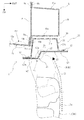
本発明の第2実施形態について、図13から図16を用いて説明する。なお、第1実施形態と共通する部分については、共通の符号を用いる等して適宜説明を省略する。また、図14は、図2と同様に車両2の前部構造を示す水平断面図であり、図13におけるD−D位置(図15におけるD´−D´位置に対応)の断面図に相当する。
[Second Embodiment]
A second embodiment of the present invention will be described with reference to FIGS. In addition, about the part which is common in 1st Embodiment, description is abbreviate | omitted suitably using a common code | symbol. 14 is a horizontal sectional view showing the front structure of the vehicle 2 as in FIG. 2, and corresponds to a sectional view taken along the line DD in FIG. 13 (corresponding to the position D′-D ′ in FIG. 15). To do.

図13および図15に示すように、本実施形態に係る車両前部構造61が備えるガセット部材70は、ガセットフロントパネル本体部41に対して段差部21を形成する段差形成部42から車幅方向内側に延設された延設部78を有する点で、第1実施形態のガセット部材20と異なる。延設部78は、段差部21よりも車幅方向内側に延設され、車両2の車室の車体前方側に位置する薄板部であるトルクボックス15の車体前方側に位置し、トルクボックス15の少なくとも一部を車体前方側から覆う部分である。   As shown in FIGS. 13 and 15, the gusset member 70 provided in the vehicle front structure 61 according to the present embodiment extends from the step forming portion 42 that forms the step portion 21 with respect to the gusset front panel main body portion 41 in the vehicle width direction. It differs from the gusset member 20 of 1st Embodiment by the point which has the extension part 78 extended inside. The extending portion 78 extends inward in the vehicle width direction from the stepped portion 21, and is positioned on the vehicle body front side of the torque box 15, which is a thin plate portion positioned on the vehicle body front side of the vehicle compartment of the vehicle 2. Is a portion that covers at least a part of the vehicle from the front side of the vehicle body.

図13、図14、図15に示すように、延設部78は、ガセットリアパネル30の内側フランジ部32からの車幅方向内側への延設部分であるリア延設部38と、ガセットフロントパネル40の内側フランジ部42bからの車幅方向内側への延設部分であるフロント延設部48とにより構成されている。すなわち、延設部78は、車体前後方向に互いに重なった内側フランジ部32と内側フランジ部42bとの両方が互いに重なった状態のまま車幅方向内側に延設された部分であり、リア延設部38およびフロント延設部48による2重の板状部により構成されている。   As shown in FIGS. 13, 14, and 15, the extending portion 78 includes a rear extending portion 38 that extends from the inner flange portion 32 of the gusset rear panel 30 in the vehicle width direction, and a gusset front panel. The front extending portion 48 is a portion extending inward in the vehicle width direction from the 40 inner flange portion 42b. That is, the extending portion 78 is a portion that extends inward in the vehicle width direction with both the inner flange portion 32 and the inner flange portion 42b that overlap each other in the longitudinal direction of the vehicle body, and extends rearward. It is composed of a double plate-like portion formed by the portion 38 and the front extending portion 48.

リア延設部38およびフロント延設部48は、互いに略同じ外形を有し、その外形を互いに略一致させた状態で重なり合っている。本実施形態では、リア延設部38およびフロント延設部48は、ガセットリアパネル30およびガセットフロントパネル40においてそれぞれガセット長手方向の全体にわたって設けられている内側フランジ部32および内側フランジ部42bがそのまま延設された形状部分となっている。したがって、リア延設部38およびフロント延設部48は、ガセットリアパネル30およびガセットフロントパネル40のそれぞれにおいてガセット長手方向の全体にわたって設けられており、正面視でガセット長手方向の寸法をガセット部材70の全体の寸法と同じくする略縦長矩形状の部分として設けられている。ただし、延設部78は、リア延設部38およびフロント延設部48のいずれか一方のみにより構成されてもよい。つまり、延設部78としては、ガセットリアパネル30およびガセットフロントパネル40の少なくともいずれか一方の部材により構成された部分であればよい。   The rear extending portion 38 and the front extending portion 48 have substantially the same outer shape, and are overlapped with the outer shapes being substantially coincident with each other. In the present embodiment, the rear extending portion 38 and the front extending portion 48 are formed by extending the inner flange portion 32 and the inner flange portion 42b provided in the gusset rear panel 30 and the gusset front panel 40, respectively, over the entire gusset longitudinal direction. It is a shaped part. Therefore, the rear extending portion 38 and the front extending portion 48 are provided over the entire gusset longitudinal direction in each of the gusset rear panel 30 and the gusset front panel 40, and the dimensions of the gusset longitudinal direction of the gusset member 70 are determined in front view. It is provided as a substantially vertically long rectangular portion having the same overall dimensions. However, the extending portion 78 may be configured by only one of the rear extending portion 38 and the front extending portion 48. That is, the extending portion 78 may be a portion configured by at least one member of the gusset rear panel 30 and the gusset front panel 40.

図14に示すように、本実施形態において、延設部78は、車幅方向について、ガセット部材70の車幅方向外側の端部の位置からガセットリアパネル30のガセットリアパネル本体部31と内側フランジ部32との境目部分(屈曲部分)の位置までの寸法を寸法N1とした場合、延設部78の延設方向の寸法N2は、寸法N1と略同じ程度である。つまり、延設部78は、ガセット幅方向について、ガセット部材70全体の略半分の範囲を占めるように、ガセット部材70の車幅方向内側に設けられている。   As shown in FIG. 14, in the present embodiment, the extending portion 78 includes a gusset rear panel main body 31 and an inner flange portion of the gusset rear panel 30 from the position of the outer end portion of the gusset member 70 in the vehicle width direction in the vehicle width direction. When the dimension up to the position of the boundary part (bent part) with respect to 32 is defined as the dimension N1, the dimension N2 in the extending direction of the extending part 78 is approximately the same as the dimension N1. That is, the extending portion 78 is provided on the inner side in the vehicle width direction of the gusset member 70 so as to occupy a substantially half range of the entire gusset member 70 in the gusset width direction.

延設部78の延設長さに関し、車体骨格構造との関係において、延設部78は、ダッシュパネル13の車幅方向外側の部分を車体前方側から覆うように設けられている。つまり、延設部78は、正面視で少なくともダッシュパネル13の一部にオーバーラップする位置まで車幅方向内側に延出している。したがって、ガセット部材70は、内側側壁部31cや段差面形成部42a等の部分によってダッシュパネル13とフロントピラー5との接合部分を車体前方側から覆うとともに、延設部78により、その接合部分に含まれるサイドフランジ部13bに対して車幅方向内側に位置するダッシュパネル本体部13aの車幅方向外側の一部を車体前方側から覆う。   Regarding the extension length of the extension part 78, the extension part 78 is provided so as to cover a portion of the dash panel 13 on the outer side in the vehicle width direction from the front side of the vehicle body in relation to the vehicle body skeleton structure. That is, the extending portion 78 extends inward in the vehicle width direction until it overlaps at least a part of the dash panel 13 in a front view. Therefore, the gusset member 70 covers the joint portion between the dash panel 13 and the front pillar 5 from the front side of the vehicle body by the inner side wall portion 31c, the stepped surface forming portion 42a, and the like, and the extension portion 78 attaches the joint portion to the joint portion. A portion of the dash panel body 13a located on the inner side in the vehicle width direction with respect to the included side flange portion 13b is covered from the vehicle body front side.

また、延設部78の延設長さに関し、車体骨格構造との関係において、延設部78は、車両衝突時において内回りしながら後退するフロントタイヤ3(ホイル3a)の軌跡に干渉する位置に及ぶように設けられている。すなわち、延設部78は、ガセット部材20が存在しない場合にダッシュパネル13においてフロントタイヤ3(ホイル3a)が衝撃を与えることになる部分を含む範囲で、ダッシュパネル13の一部を車体前方側から覆うように設けられる。   Further, with respect to the extension length of the extension part 78, the extension part 78 is in a position that interferes with the locus of the front tire 3 (foil 3 a) that retreats while turning inward during a vehicle collision. It is provided to extend. That is, the extended portion 78 includes a portion of the dash panel 13 on the front side of the vehicle body within a range including a portion of the dash panel 13 where the front tire 3 (foil 3a) gives an impact when the gusset member 20 is not present. It is provided so as to cover.

なお、本実施形態のガセット部材70において、延設部78を構成するガセットリアパネル30のリア延設部38は、第1実施形態に係るガセット部材20がガセットリアパネル30において有する下端延出部34を含む範囲で設けられている。このため、本実施形態に係るガセットフロントパネル40は、第1実施形態に係るガセットフロントパネル40が有する3つの作業孔46に加え、フロント延設部48の締結孔36(36e)に対応する位置に、4つめの作業孔46dを有する(図15参照)。   In the gusset member 70 of the present embodiment, the rear extension portion 38 of the gusset rear panel 30 constituting the extension portion 78 has a lower end extension portion 34 that the gusset member 20 according to the first embodiment has in the gusset rear panel 30. It is provided in the range including. Therefore, the gusset front panel 40 according to the present embodiment corresponds to the fastening holes 36 (36e) of the front extension 48 in addition to the three working holes 46 of the gusset front panel 40 according to the first embodiment. And has a fourth working hole 46d (see FIG. 15).

また、ガセットリアパネル30とガセットフロントパネル40の相互の溶接構造に関し、本実施形態のガセット部材70においては、第1実施形態のガセット部材20において互いに重なる内側フランジ部32と内側フランジ部42bの部分に設けられるスポット溶接による溶接部に加えてまたは同溶接部に代えて、延設部78に溶接部が適宜設けられる。延設部78に溶接部が設けられる場合、例えば、延設部78の車幅方向内側の縁部において、内側フランジ部32と内側フランジ部42b同士の接合部分と同様に、ガセット長手方向に適宜間隔を隔てて複数の溶接部が設けられる。   Further, regarding the mutual welding structure of the gusset rear panel 30 and the gusset front panel 40, in the gusset member 70 of the present embodiment, the inner flange portion 32 and the inner flange portion 42b overlap each other in the gusset member 20 of the first embodiment. In addition to the welded portion by spot welding provided or instead of the welded portion, the extended portion 78 is appropriately provided with a welded portion. When the welded portion is provided in the extended portion 78, for example, at the edge portion on the inner side in the vehicle width direction of the extended portion 78, as in the joint portion between the inner flange portion 32 and the inner flange portion 42 b, the gusset is appropriately set in the longitudinal direction. A plurality of welds are provided at intervals.

本実施形態に係る車両前部構造61によれば、第1実施形態に係る車両前部構造1により得られる作用効果に加えて、次のような作用効果を得ることができる。   According to the vehicle front structure 61 according to the present embodiment, in addition to the functions and effects obtained by the vehicle front structure 1 according to the first embodiment, the following functions and effects can be obtained.

図14に示すように、本実施形態に係る車両前部構造61によれば、ガセット部材70が延設部78を有することにより、車両2の車両衝突時に内回りしながら後退するフロントタイヤ3が仮にフロントタイヤ3の挙動等によって段差部21を越えて車両2の内側に侵入した場合であっても、フロントタイヤ3(ホイル3a)は、延設部78に衝突することになる(符号P1で示す部分参照)。   As shown in FIG. 14, according to the vehicle front portion structure 61 according to the present embodiment, the front tire 3 that retreats while turning inward at the time of a vehicle collision of the vehicle 2 is temporarily provided because the gusset member 70 has the extending portion 78. Even if the front tire 3 moves beyond the stepped portion 21 and enters the inside of the vehicle 2 due to the behavior of the front tire 3 or the like, the front tire 3 (foil 3a) collides with the extended portion 78 (indicated by reference sign P1). Part reference).

このように、本実施形態に係る車両前部構造61によれば、延設部78がダッシュパネル13の車体前方側に存在することにより、車両衝突時におけるフロントタイヤ3の挙動等にかかわらず、フロントタイヤ3(ホイル3a)がダッシュパネル13の変形量を大きくすることを確実に防止することができ、車両2への想定外の入力を防ぐことができる。これにより、フロントタイヤ3が衝撃を与えることによるダッシュパネル13の変形等を防止することができ、安全性の向上を図ることができる。   As described above, according to the vehicle front structure 61 according to the present embodiment, the extending portion 78 is present on the vehicle body front side of the dash panel 13, so that regardless of the behavior of the front tire 3 at the time of the vehicle collision, It is possible to reliably prevent the front tire 3 (the wheel 3a) from increasing the deformation amount of the dash panel 13, and to prevent an unexpected input to the vehicle 2. Thereby, the deformation | transformation etc. of the dash panel 13 by the front tire 3 giving an impact can be prevented, and the improvement of safety | security can be aimed at.

そして、本実施形態に係る車両前部構造61によれば、延設部78により、車両衝突時におけるフロントタイヤ3(ホイル3a)の挙動等に対応して、ガセット部材70をダッシュパネル13の補強したい部位(保護したい部位)まで必要に応じて拡大することで、フロントタイヤ3(ホイル3a)がダッシュパネル13へ衝撃を与えることを回避することができる。このように、本実施形態に係る車両前部構造61によれば、延設部78によってダッシュパネル13等の薄板部について必要な部位のみ補強することができる。このため、ダッシュパネル13を補強するために例えばダッシュパネル13全体の板厚を厚くする必要がなく、質量増加を最小限に抑えながら、ダッシュパネル13を効率的に補強することができる。   And according to the vehicle front part structure 61 which concerns on this embodiment, the extension part 78 strengthens the gusset member 70 of the dash panel 13 according to the behavior etc. of the front tire 3 (wheel 3a) at the time of a vehicle collision. It is possible to avoid the front tire 3 (foil 3a) from giving an impact to the dash panel 13 by enlarging the part to be desired (part to be protected) as necessary. As described above, according to the vehicle front portion structure 61 according to the present embodiment, only necessary portions of the thin plate portion such as the dash panel 13 can be reinforced by the extending portion 78. For this reason, in order to reinforce the dash panel 13, for example, it is not necessary to increase the thickness of the entire dash panel 13, and the dash panel 13 can be efficiently reinforced while minimizing an increase in mass.

すなわち、本実施形態に係る車両前部構造61によれば、ガセット部材70において、車体骨格構造の補強構造として必要な範囲まで拡大された構成である延設部78を有することで、必要部位のみガセット部材70によって補強・保護することが可能となるため、ダッシュパネル13の全体の板厚を厚くする等の必要がなく、車両衝突に対する衝突性能の向上と、車体の軽量化の両立を図ることが可能となる。   In other words, according to the vehicle front structure 61 according to the present embodiment, the gusset member 70 includes the extending portion 78 that is configured to be expanded to a range necessary as a reinforcing structure for the vehicle body skeleton structure, so that only necessary portions are included. Since it is possible to reinforce and protect by the gusset member 70, it is not necessary to increase the overall thickness of the dash panel 13, and to improve both the collision performance with respect to the vehicle collision and the weight reduction of the vehicle body. Is possible.

なお、本実施形態では、ガセットリアパネル30およびガセットフロントパネル40のそれぞれを構成する鋼板の一部として延設部78が設けられているが、延設部78は、ガセットリアパネル30およびガセットフロントパネル40とは別体の部材により構成されてもよい。ただし、本実施形態のように、ガセットリアパネル30およびガセットフロントパネル40の一部により延設部78が設けられる構成によれば、別途部品を追加することなく、容易に延設部78を設けることができ、上述したような作用効果を達成することができる。また、本実施形態では、延設部78は、ガセット部材70のガセット長手方向の全体にわたる延設部分として設けられているが、これに限定されず、補強する部位等に応じて、ガセット長手方向について部分的に延設された部分であってもよい。   In the present embodiment, the extending portion 78 is provided as a part of the steel plate constituting each of the gusset rear panel 30 and the gusset front panel 40. However, the extending portion 78 includes the gusset rear panel 30 and the gusset front panel 40. It may be composed of a separate member. However, according to the configuration in which the extending portion 78 is provided by a part of the gusset rear panel 30 and the gusset front panel 40 as in the present embodiment, the extending portion 78 can be easily provided without additional components. And the effects as described above can be achieved. In the present embodiment, the extending portion 78 is provided as an extending portion of the entire gusset member 70 in the longitudinal direction of the gusset, but is not limited to this, and depending on the portion to be reinforced, the longitudinal direction of the gusset It may be a partially extended portion.

以上のように、実施形態を用いて説明した本発明に係る車両前部構造によれば、車両前部衝突時のタイヤ(ホイル)の挙動の制御と車体の骨格補強との両立を達成することができる。なお、上記の各実施形態では、図面において車体の左側に設けられるガセット部材のみを示しているが、車両2は、車体の右側にガセット部材を備える構成であったり、車幅方向について対称に構成された左右一対のガセット部材を備える構成であったりしてもよい。すなわち、ガセット部材は、車幅方向の両側(左右両側)のフロントピラー5の少なくとも一方のフロントピラー5の車体前方側、つまり車体の左側および右側の少なくとも一側に設けられればよい。なお、ガセット部材が車体の左右片側のみに設けられる場合は、例えば、車両2の運転席の配置に応じて、運転席が配置される側にガセット部材が設けられる。   As described above, according to the vehicle front structure according to the present invention described with reference to the embodiment, it is possible to achieve both the control of the behavior of the tire (foil) at the time of the vehicle front collision and the frame reinforcement of the vehicle body. Can do. In the above embodiments, only the gusset member provided on the left side of the vehicle body is shown in the drawings. However, the vehicle 2 is configured to include the gusset member on the right side of the vehicle body or configured symmetrically with respect to the vehicle width direction. It may be configured to include a pair of left and right gusset members. That is, the gusset member may be provided on the vehicle body front side of at least one of the front pillars 5 on both sides (right and left sides) in the vehicle width direction, that is, on at least one side of the left and right sides of the vehicle body. When the gusset member is provided only on the left and right sides of the vehicle body, for example, the gusset member is provided on the side where the driver's seat is arranged according to the arrangement of the driver's seat of the vehicle 2.

また、各実施形態により説明した本発明に係る車両前部構造は、上述した実施形態に限定されず、本発明の趣旨に沿う範囲で、種々の態様を採用することができる。例えば、上述した実施形態では、ガセット部材20は、車体骨格構造に対し、合計で5箇所のボルト締結による固定部により、ロッカ4、フロントピラー5、およびトルクボックス15の3つの部材に跨って固定されているが、ガセット部材20の車体骨格構造に対する固定構造は、特に限定されるものではない。つまり、ガセット部材20は、車体骨格構造を構成するいずれか1つまたは複数の部材、言い換えると車体骨格構造のいずれかの部位に固定されればよい。ただし、車体骨格構造に対し、例えば上述した実施形態のようにロッカ4、フロントピラー5、およびトルクボックス15の3つの部材等の複数の部材に跨ってガセット部材20を固定する構成によれば、ガセット部材20によってこれら3つの部材間の連結構造を補強することができるので、ガセット部材20による車体骨格構造に対する補強の作用を効果的に得ることができる。また、ガセット部材20の車体骨格構造に対する固定には、ボルト締結のほか、溶接等が用いられてもよい。   In addition, the vehicle front structure according to the present invention described in each embodiment is not limited to the above-described embodiment, and various modes can be adopted within the scope of the gist of the present invention. For example, in the above-described embodiment, the gusset member 20 is fixed across the three members of the rocker 4, the front pillar 5, and the torque box 15, with a total of five bolt fastening portions to the vehicle body skeleton structure. However, the fixing structure of the gusset member 20 with respect to the vehicle body skeleton structure is not particularly limited. That is, the gusset member 20 may be fixed to any one or a plurality of members constituting the vehicle body skeleton structure, in other words, to any part of the vehicle body skeleton structure. However, according to the configuration in which the gusset member 20 is fixed over a plurality of members such as the three members of the rocker 4, the front pillar 5, and the torque box 15 as in the above-described embodiment, for example, in the vehicle body skeleton structure. Since the connection structure between these three members can be reinforced by the gusset member 20, the reinforcing action of the gusset member 20 on the vehicle body skeleton structure can be effectively obtained. For fixing the gusset member 20 to the vehicle body skeleton structure, welding or the like may be used in addition to bolt fastening.

また、上述した実施形態では、ガセット部材20は鉄製の部材として構成されているが、ガセット部材20の材料は、鉄鋼材料に限定されることなく、所望の強度が得られるものであれば、他の金属材料や樹脂材料等であってもよい。   Moreover, in embodiment mentioned above, although the gusset member 20 is comprised as an iron member, the material of the gusset member 20 is not limited to a steel material, if it can obtain desired intensity | strength and others. Metal materials or resin materials may be used.

また、上述した実施形態では、ガセット部材20は、ガセットリアパネル30およびガセットフロントパネル40の2枚のパネル部材の重ね合わせにより構成されているが、例えば1枚のパネル部材等のような一体の部材により構成されたものであってもよい。ただし、ガセット部材20において段差部21等の所定の形状部分を形成するための加工の容易さや軽量化や強度確保の観点からは、ガセット部材20の構成としては、上述した本実施形態のようにガセットリアパネル30およびガセットフロントパネル40からなる中空状の構成が好ましい。   Further, in the above-described embodiment, the gusset member 20 is configured by overlapping two panel members of the gusset rear panel 30 and the gusset front panel 40. For example, an integral member such as a single panel member or the like is used. It may be constituted by. However, from the viewpoint of ease of processing for forming a predetermined shape portion such as the stepped portion 21 in the gusset member 20, weight reduction, and securing strength, the configuration of the gusset member 20 is as in the above-described embodiment. A hollow configuration including the gusset rear panel 30 and the gusset front panel 40 is preferable.

すなわち、例えばガセット部材20を一体のパネル部材により構成した場合、所望の強度を得るために板厚が厚くなるため、段差部21等の所定の形状部分を形成するための加工が困難となり、重量も重くなる。この点、ガセット部材20を2枚のパネル部材の重ね合わせにより中空状に構成することにより、各パネル部材の板厚を薄くすることができるので、所定の形状部分を形成するための加工が容易となるとともに、軽量で変形しにくい構造を効率的に実現することができる。   That is, for example, when the gusset member 20 is constituted by an integral panel member, the plate thickness is increased in order to obtain a desired strength, so that processing for forming a predetermined shape portion such as the step portion 21 becomes difficult, and the weight Also gets heavier. In this regard, by forming the gusset member 20 into a hollow shape by superimposing two panel members, the thickness of each panel member can be reduced, so that processing for forming a predetermined shape portion is easy. At the same time, it is possible to efficiently realize a lightweight structure that is difficult to deform.

また、ガセット部材20の形状に関しては、上述した実施形態では、ガセット部材20は、正面視で略縦長矩形状の外形をなすように構成されているが、ガセット部材20の全体的な形状は特に限定されない。したがって、ガセット部材20としては、正面視で略長円形状の外形をなすような部材であったり、車幅方向を長手方向とする略横長矩形状の外形をなすような部材であったりしてもよい。   Further, regarding the shape of the gusset member 20, in the above-described embodiment, the gusset member 20 is configured to have a substantially vertically long outer shape in front view, but the overall shape of the gusset member 20 is particularly It is not limited. Therefore, the gusset member 20 may be a member that has a substantially oval outer shape when viewed from the front, or a member that has a substantially horizontally long rectangular shape whose longitudinal direction is the vehicle width direction. Also good.

また、上述した実施形態では、ガセット部材20が有する段差部21が形成する段差面22は、車幅方向外側斜め前を向く面となっているが、段差面22は、概ね車幅方向外側を向く面であればよい。したがって、段差面22としては、平面視で車幅方向に直交するような車体前後方向に沿う面であったり、車幅方向外側斜め後を向く面であったりしてもよい。   Further, in the above-described embodiment, the step surface 22 formed by the step portion 21 of the gusset member 20 is a surface facing obliquely forward in the vehicle width direction, but the step surface 22 is substantially in the vehicle width direction outside. Any surface can be used. Therefore, the stepped surface 22 may be a surface along the vehicle body front-rear direction orthogonal to the vehicle width direction in a plan view or a surface facing diagonally rearward in the vehicle width direction.

1 車両前部構造
2 車両
3 フロントタイヤ
4 ロッカ
5 フロントピラー
10 サイドメンバアウタパネル
13 ダッシュパネル
15 トルクボックス
20 ガセット部材
21 段差部
22 段差面
24 空間
26 バルク形状部
27 稜線
30 ガセットリアパネル
31a 後壁部
40 ガセットフロントパネル
41 ガセットフロントパネル本体部
61 車両前部構造
70 ガセット部材
78 延設部
DESCRIPTION OF SYMBOLS 1 Vehicle front part structure 2 Vehicle 3 Front tire 4 Rocker 5 Front pillar 10 Side member outer panel 13 Dash panel 15 Torque box 20 Gusset member 21 Step part 22 Step surface 24 Space 26 Bulk-shaped part 27 Ridge line 30 Gusset rear panel 31a Rear wall part 40 Gusset front panel 41 Gusset front panel body 61 Vehicle front structure 70 Gusset member 78 Extension

Claims (3)

車両の車体下部の車幅方向の両外側に車体前後方向を長手方向として配設されるロッカと、
前記ロッカの車体前方側の端部から車体上方へ向けて延設されるフロントピラーと、
前記ロッカの車体前方に配置されるフロントタイヤと、
前記フロントピラーの車体前方側に、前記ロッカおよび前記フロントピラーを含む車体の骨格構造に固定された状態で、少なくとも前記フロントタイヤと車体上下方向でオーバーラップする位置に設けられ、前記フロントピラーの車体前方側の下部の少なくとも一部を覆うガセット部材と、を備え、
前記ガセット部材は、車体前方側に、車体上下方向に沿うとともに車幅方向外側の部分に対して車幅方向内側の部分を相対的に車体前方側に位置させる段差部を有し、前記ガセット部材の車体後方側の部分を構成するとともに前記骨格構造に固定される後側部材と、前記ガセット部材の車体前方側の部分を構成するとともに前記段差部を形成する前側部材とにより構成され、しかも、横断面形状として前記後側部材の一部である車体後方側の壁部および前記前側部材の一部である車体前方側の壁部を含む壁面構造により略閉断面形状または閉断面形状をなして中空状に構成されており、
前記段差部は、前記ガセット部材の車幅方向外側の本体部分に対して車体前方側に立ち上がるとともに車幅方向外側を向く段差面を形成する部分である、
車両前部構造。
A rocker disposed on both outer sides in the vehicle width direction of the lower body of the vehicle with the longitudinal direction of the vehicle body as a longitudinal direction;
A front pillar extending from the front end of the rocker toward the vehicle body;
A front tire disposed in front of the rocker body;
The vehicle body of the front pillar is provided on the vehicle body front side of the front pillar at a position overlapping at least the front tire in the vehicle body vertical direction while being fixed to the frame structure of the vehicle body including the rocker and the front pillar. A gusset member that covers at least a part of the lower part on the front side, and
The gusset member to the front side of the vehicle body, has a step portion for positioning the vehicle width direction inside part relatively front side of the vehicle body with respect to the vehicle width direction outer part together along the vertical direction of the vehicle body, said gusset member A rear side member that constitutes a portion on the vehicle body rear side and is fixed to the skeleton structure, and a front side member that constitutes a portion on the vehicle body front side of the gusset member and forms the step portion, As a cross-sectional shape , a substantially closed cross-sectional shape or a closed cross-sectional shape is formed by a wall surface structure including a vehicle body rear side wall portion which is a part of the rear member and a vehicle body front side wall portion which is a part of the front member. It is configured in a hollow shape ,
The step portion is Ah Ru in portion forming a stepped surface facing the outside in the vehicle width direction together with the rising front of the vehicle body side with respect to the vehicle width direction outer side of the body portion of the gusset member,
Vehicle front structure.
前記ガセット部材は、
車幅方向内側に延設され、車両の車室の車体前方側に位置する薄板部の車体前方側に位置し、前記薄板部の少なくとも一部を車体前方側から覆う延設部をさらに有する、
請求項1に記載の車両前部構造。
The gusset member is
An extension portion extending inward in the vehicle width direction, positioned on the vehicle body front side of the thin plate portion positioned on the vehicle body front side of the vehicle compartment, and covering at least a part of the plate portion from the vehicle body front side;
The vehicle front structure according to claim 1.
前記ガセット部材は、
車体上下方向を長手方向とし、
中空状の内部に設けられ、稜線を形成するとともに前記車体後方側の壁部と前記車体前方側の壁部との車体前後方向の間隔を部分的に狭くするバルク形状部をさらに有する、
請求項1または請求項2に記載の車両前部構造。
The gusset member is
The longitudinal direction of the vehicle body is the longitudinal direction,
A bulk-shaped portion that is provided in a hollow shape and that forms a ridge line and partially narrows the distance in the vehicle longitudinal direction between the wall portion on the vehicle body rear side and the wall portion on the vehicle body front side;
The vehicle front part structure according to claim 1 or 2.
JP2014147585A 2014-07-18 2014-07-18 Vehicle front structure Active JP6185437B2 (en)

Priority Applications (2)

Application Number Priority Date Filing Date Title
JP2014147585A JP6185437B2 (en) 2014-07-18 2014-07-18 Vehicle front structure
US14/797,906 US9821853B2 (en) 2014-07-18 2015-07-13 Vehicle front part structure

Applications Claiming Priority (1)

Application Number Priority Date Filing Date Title
JP2014147585A JP6185437B2 (en) 2014-07-18 2014-07-18 Vehicle front structure

Publications (2)

Publication Number Publication Date
JP2016022813A JP2016022813A (en) 2016-02-08
JP6185437B2 true JP6185437B2 (en) 2017-08-23

Family

ID=55073919

Family Applications (1)

Application Number Title Priority Date Filing Date
JP2014147585A Active JP6185437B2 (en) 2014-07-18 2014-07-18 Vehicle front structure

Country Status (2)

Country Link
US (1) US9821853B2 (en)
JP (1) JP6185437B2 (en)

Families Citing this family (20)

* Cited by examiner, † Cited by third party
Publication number Priority date Publication date Assignee Title
JP5987800B2 (en) * 2013-08-21 2016-09-07 トヨタ自動車株式会社 Body front structure
JP5983570B2 (en) * 2013-09-17 2016-08-31 トヨタ自動車株式会社 Vehicle side structure
JP6112083B2 (en) * 2014-08-21 2017-04-12 トヨタ自動車株式会社 Body front structure
JP6137096B2 (en) * 2014-09-19 2017-05-31 トヨタ自動車株式会社 Vehicle side structure
JP6135700B2 (en) * 2015-03-11 2017-05-31 トヨタ自動車株式会社 Body front structure
DE102016110578B8 (en) * 2016-06-08 2018-06-28 Linde + Wiemann SE & Co. KG Structural component for a motor vehicle with reinforcing element
US10899393B2 (en) * 2017-03-14 2021-01-26 Honda Motor Co., Ltd. Rear body structure
US10077014B1 (en) * 2017-03-20 2018-09-18 GM Global Technology Operations LLC Body-mounted tire blocker assembly
JP6610595B2 (en) * 2017-03-27 2019-11-27 トヨタ自動車株式会社 Pillar structure for vehicles
US10214243B2 (en) * 2017-07-11 2019-02-26 Ford Global Technologies, Llc Vehicle frame
KR102429057B1 (en) * 2017-10-11 2022-08-04 현대자동차주식회사 Collision Load Multi Decentralization type Side Body Frame and Vehicle thereby
JP6977614B2 (en) * 2018-02-23 2021-12-08 トヨタ自動車株式会社 Vehicle undercarriage
EP3766762B1 (en) * 2018-10-31 2023-07-26 Nippon Steel Corporation Automobile frame member
JP7003958B2 (en) * 2019-03-27 2022-01-21 マツダ株式会社 Vehicle front body structure
US10913499B2 (en) 2019-05-08 2021-02-09 Ford Global Technologies, Llc Vehicle hinge pillar assembly
US10926806B2 (en) 2019-05-20 2021-02-23 Ford Global Technologies, Llc Vehicle torque box assembly
JP7243438B2 (en) * 2019-05-22 2023-03-22 トヨタ自動車株式会社 vehicle front structure
DE102019218665A1 (en) 2019-12-02 2021-06-02 Ford Global Technologies, Llc Crash structure for a motor vehicle
US11827167B2 (en) * 2020-06-25 2023-11-28 Rivian Ip Holdings, Llc Wheel deflector for a small overlap crash
JP7351817B2 (en) 2020-09-04 2023-09-27 トヨタ自動車株式会社 car body

Family Cites Families (31)

* Cited by examiner, † Cited by third party
Publication number Priority date Publication date Assignee Title
FR2673590B1 (en) * 1991-03-07 1993-08-13 Pomero Claude DEVICE FOR DEFLECTING THE WHEELS OF A MOTOR VEHICLE AT THE TIME OF A COLLISION.
JP3140506B2 (en) * 1991-09-30 2001-03-05 マツダ株式会社 Car front body structure
DE19836851C1 (en) * 1998-08-14 2000-03-30 Daimler Chrysler Ag Protective arrangement on a wheel arch of a motor vehicle body-in-white structure
US6364358B1 (en) 2000-03-21 2002-04-02 Honda Giken Kogyo Kabushiki Kaisha Side sill load path initiator
JP2002154458A (en) * 2000-11-24 2002-05-28 Fuji Heavy Ind Ltd Car body front structure
JP2003002247A (en) * 2001-06-26 2003-01-08 Nissan Motor Co Ltd Front structure of vehicle body
JP3988745B2 (en) * 2004-05-06 2007-10-10 日産自動車株式会社 Body floor structure
JP4254843B2 (en) * 2006-10-25 2009-04-15 トヨタ自動車株式会社 Vehicle front structure
JP4486673B2 (en) * 2007-12-11 2010-06-23 本田技研工業株式会社 Body structure
JP2009298214A (en) * 2008-06-11 2009-12-24 Toyota Motor Corp Vehicle front part structure
JP2010047178A (en) * 2008-08-22 2010-03-04 Toyota Motor Corp Vehicle body front side end structure of rocker
EP2361822B1 (en) * 2008-12-22 2014-08-13 Toyota Jidosha Kabushiki Kaisha Vehicle body forward portion structure
US8276976B2 (en) * 2009-09-02 2012-10-02 Honda Motor Co., Ltd. Vehicle body front structure
DE102010034932A1 (en) * 2010-08-20 2012-02-23 Gm Global Technology Operations Llc (N.D.Ges.D. Staates Delaware) Motor vehicle body with structurally reinforced front frame connection
BR112014020026A8 (en) * 2012-02-13 2017-07-11 Honda Motor Co Ltd VEHICLE BODY LOWER STRUCTURE
US20130285414A1 (en) * 2012-04-25 2013-10-31 Ford Global Technologies, Llc Automatic vehicle stiffened pillar assembly
US8469442B1 (en) * 2012-06-27 2013-06-25 Nissan North America, Inc. Vehicle front body structure
JP5971059B2 (en) * 2012-09-28 2016-08-17 マツダ株式会社 Vehicle structure
DE102013101698B4 (en) * 2013-02-20 2022-03-24 Dr. Ing. H.C. F. Porsche Aktiengesellschaft motor vehicle support structure
DE102013101697A1 (en) * 2013-02-20 2014-08-21 Dr. Ing. H.C. F. Porsche Aktiengesellschaft Motor vehicle support structure
EP2979957B1 (en) * 2013-03-26 2017-08-23 Toyota Jidosha Kabushiki Kaisha Automobile front pillar bottom structure
JP5987800B2 (en) * 2013-08-21 2016-09-07 トヨタ自動車株式会社 Body front structure
US9365245B2 (en) * 2013-11-08 2016-06-14 Ford Global Technologies, Llc Load management device
KR101575320B1 (en) * 2013-12-16 2015-12-07 현대자동차 주식회사 Vehicle body reinforcing structure
JP2015116979A (en) 2013-12-19 2015-06-25 トヨタ自動車株式会社 Vehicle body lower part structure
US9187133B2 (en) * 2014-03-03 2015-11-17 Honda Motor Co., Ltd. Front pillar construction having reinforcement member for vehicle frame
US9352789B2 (en) * 2014-04-17 2016-05-31 Tesla Motors, Inc. Torque box with shear planes at inner joint
JP6112083B2 (en) * 2014-08-21 2017-04-12 トヨタ自動車株式会社 Body front structure
US9272736B1 (en) * 2014-09-03 2016-03-01 Toyota Motor Engineering & Manufacturing North America, Inc. Vehicles having a dash panel reinforcement member
US9533712B2 (en) * 2014-10-20 2017-01-03 GM Global Technology Operations LLC Wheel catcher assembly
US9469347B1 (en) * 2015-07-07 2016-10-18 Toyota Motor Engineering & Manufacturing North America, Inc. Vehicles including a wheel well reinforcement member

Also Published As

Publication number Publication date
US9821853B2 (en) 2017-11-21
JP2016022813A (en) 2016-02-08
US20160016612A1 (en) 2016-01-21

Similar Documents

Publication Publication Date Title
JP6185437B2 (en) Vehicle front structure
JP6211107B2 (en) Lower body structure
JP6409724B2 (en) Car side body structure
US8960780B2 (en) Vehicle side body structure
JP5895701B2 (en) Body front structure
JP5776208B2 (en) Vehicle front structure
US10065681B2 (en) Vehicle lower section structure
WO2012096244A1 (en) Structure for front hood of automobile
JP5976615B2 (en) Vehicle body structure and vehicle body manufacturing method
JP5949518B2 (en) Vehicle side body structure
JP6439401B2 (en) Side sill reinforcement structure
JP6191046B2 (en) Automobile front pillar structure
JP6961666B2 (en) Body side structure
JP6164184B2 (en) Automotive hood structure
JP6016246B2 (en) Auto body structure
CN114132388B (en) Vehicle body
JP5888560B2 (en) Car floor structure
JP5783147B2 (en) Vehicle lower structure
JP5858365B2 (en) Car floor structure
JP6187427B2 (en) Rear body structure of the vehicle
CN111776077A (en) Front pillar structure for vehicle
JP6076159B2 (en) vehicle
JP6076161B2 (en) vehicle
JP6360679B2 (en) Vehicle body structure and vehicle body manufacturing method
JP7072024B2 (en) Body front structure

Legal Events

Date Code Title Description
A977 Report on retrieval

Free format text: JAPANESE INTERMEDIATE CODE: A971007

Effective date: 20160629

A131 Notification of reasons for refusal

Free format text: JAPANESE INTERMEDIATE CODE: A131

Effective date: 20160705

A521 Request for written amendment filed

Free format text: JAPANESE INTERMEDIATE CODE: A523

Effective date: 20160823

A131 Notification of reasons for refusal

Free format text: JAPANESE INTERMEDIATE CODE: A131

Effective date: 20161206

A521 Request for written amendment filed

Free format text: JAPANESE INTERMEDIATE CODE: A523

Effective date: 20170202

TRDD Decision of grant or rejection written
A01 Written decision to grant a patent or to grant a registration (utility model)

Free format text: JAPANESE INTERMEDIATE CODE: A01

Effective date: 20170704

A61 First payment of annual fees (during grant procedure)

Free format text: JAPANESE INTERMEDIATE CODE: A61

Effective date: 20170727

R150 Certificate of patent or registration of utility model

Ref document number: 6185437

Country of ref document: JP

Free format text: JAPANESE INTERMEDIATE CODE: R150

R250 Receipt of annual fees

Free format text: JAPANESE INTERMEDIATE CODE: R250

R250 Receipt of annual fees

Free format text: JAPANESE INTERMEDIATE CODE: R250

R250 Receipt of annual fees

Free format text: JAPANESE INTERMEDIATE CODE: R250