EP1595746B1 - Vehicle luggage compartment cover - Google Patents
Vehicle luggage compartment cover Download PDFInfo
- Publication number
- EP1595746B1 EP1595746B1 EP20050010117 EP05010117A EP1595746B1 EP 1595746 B1 EP1595746 B1 EP 1595746B1 EP 20050010117 EP20050010117 EP 20050010117 EP 05010117 A EP05010117 A EP 05010117A EP 1595746 B1 EP1595746 B1 EP 1595746B1
- Authority
- EP
- European Patent Office
- Prior art keywords
- frame
- planar form
- covering element
- form according
- opening
- Prior art date
- Legal status (The legal status is an assumption and is not a legal conclusion. Google has not performed a legal analysis and makes no representation as to the accuracy of the status listed.)
- Expired - Fee Related
Links
Images

Classifications
-
- B—PERFORMING OPERATIONS; TRANSPORTING
- B60—VEHICLES IN GENERAL
- B60R—VEHICLES, VEHICLE FITTINGS, OR VEHICLE PARTS, NOT OTHERWISE PROVIDED FOR
- B60R5/00—Compartments within vehicle body primarily intended or sufficiently spacious for trunks, suit-cases, or the like
- B60R5/04—Compartments within vehicle body primarily intended or sufficiently spacious for trunks, suit-cases, or the like arranged at rear of vehicle
- B60R5/044—Compartments within vehicle body primarily intended or sufficiently spacious for trunks, suit-cases, or the like arranged at rear of vehicle luggage covering means, e.g. parcel shelves
- B60R5/045—Compartments within vehicle body primarily intended or sufficiently spacious for trunks, suit-cases, or the like arranged at rear of vehicle luggage covering means, e.g. parcel shelves collapsible or transformable
- B60R5/047—Compartments within vehicle body primarily intended or sufficiently spacious for trunks, suit-cases, or the like arranged at rear of vehicle luggage covering means, e.g. parcel shelves collapsible or transformable collapsible by rolling-up
Definitions
- the invention relates to a fabric for a load compartment cover of a motor vehicle with a passage opening which is at least partially closed by a cover, which is movable between a at least the passage opening releasing the deflection position and the passage opening covering the closed position.
- a luggage compartment cover for motor vehicles is known.
- the pull-out luggage compartment cover has, on its extension-side end region, a fabric in the form of a contoured part, in which a passage opening is provided.
- the manual intervention in the passage opening makes it possible to transfer the load compartment cover from a rest position to a use position for covering the load compartment.
- the passage opening is with a provided pivotable cover member to allow the insight through the passage opening into the loading space located below the loading space cover. This cover is held by spring force against a bottom of an edge of the passage opening. The edge of the passage opening forms a stop for the cover.
- the passage opening is inevitably pushed down from above at the appropriate intervention by the fingers of a hand of an operator from above, whereby the Kont matter can be taken in the region of the passage opening.
- the cover is hinged by a bearing axis and is held by a spring element in a closed position. The number of components and the installation is complex.
- a sheet with a through-opening is known, which is at least partially closed by a movable cover.
- the cover has a smaller footprint than a free passage opening.
- the cover is designed as freely pivotable through the access opening through, deflectable to both sides of the access opening cover flap.
- restoring means are required for both pivoting directions, which are formed by spring elements.
- These spring means are designed as torsion springs, which are provided on a separately acting on the cover flap stub axle for pivotally mounting the cover flap.
- the invention has for its object to provide a sheet of the type mentioned, which allows a simple structure for closing the passage opening.
- At least one cover has a flexurally elastic region which replaces the mechanical components at least partially.
- the flexural elastic range allows easy and comfortable manual intervention and removal the hand from the access opening.
- the cover element is transferred from the closed position into a deflection position by the elastic region. After transferring the load compartment cover in a rest position or the loading space covering position takes place an independent return of the cover in the closed position by the restoring forces, which are built up during deflection in the flexurally elastic region.
- the at least one cover is associated with a frame of thermoplastic or thermosetting material at least partially surrounding the passage opening.
- This frame engages in the passage opening on the fabric and positions the at least one cover in the passage opening.
- de frame is made of thermoplastic or thermosetting material.
- the at least one cover element is formed according to a first embodiment of the invention, at least in sections in the region of the free passage area flexurally elastic.
- the cover is thus deformable in itself, so that when engaging a hand in the passage opening only the area is deflected, which is displaced by the fingers of one hand inevitably. At the same time thereby a safe removal of the hand is possible without a risk of injury could exist through the rewinding into the closed position cover.
- the at least one bending-elastic in the region of the passage opening cover is provided according to a preferred embodiment of the invention in the at least partially surrounding the passage opening frame by a detachable or non-detachable connection.
- the detachable connection can be made for example by a clamping or screw connection.
- an adhesive, press or welded connection can be provided.
- the at least one cover element and a frame surrounding the passage opening are at least partially connected to each other by a flexurally elastic region.
- a simplification of the structure can be given.
- a frame part and a cover part arranged on a frame part are required, which consist of a part in order to close the passage opening.
- a cost-effective design and fast assembly is given hereby.
- the flexurally elastic region between the cover element and the frame is designed as a hinge connection, in particular as a film hinge. This can be given in a simple manner, the one-piece between the cover and the frame and a stable connection.
- the at least one cover is connected to an upper or lower part of a frame.
- the flexurally elastic region between the at least one cover element and the passage opening at least partially surrounding the frame at the upper or lower part can be provided.
- the at least one cover element is preferably held in a closed position by at least one return means.
- the return means advantageously engages the frame, the flexurally elastic region and / or the cover element.
- the return means By the return means, the assumption of the closed position after releasing the deflection position by removing the hand from the access opening can be supported.
- the frame Return means is attached by a detachable or non-detachable connection, which acts on an underside of the cover.
- a thickening or reinforcement is provided, whereby the cover is automatically transferred to the closed position.
- a return means may be attached to the cover, which cooperates with the frame when deflected and causes a reset in the closed position. It is understood that any combinations thereof may be provided.
- the return means is preferably made of a flexurally elastic or rubber-elastic material, which is selected depending on the size of the at least one cover in hardness.
- the return means have a Shore hardness in the range of 60 to 80 Shore.
- the at least one cover element and the at least one frame part are preferably designed according to the first or further alternative embodiment of the invention as an injection molded part.
- a one- or multi-component injection molding process is used to produce the at least one cover element and the frame surrounding the passage opening at least partially.
- the frame can be produced with a harder material and at the same time be given a one-piece connection of the cover element over a flexurally elastic region or the configuration of the cover element in the region of the free passage area as a flexurally elastic region.
- it can also be provided that only a part of the passage area of the cover element is formed by a flexurally elastic region and a hinge connection between the cover element and the frame is provided as a flexurally elastic region.
- the use of a plastic injection molding process advantageously makes it possible to apply a coating adapted to the surface structure, at least on the upper side of the covering element and the frame.
- the access opening can be adapted to aesthetic requirements.
- the surface may be painted or provided with a film corresponding to the sheet or Planware, so that the closed passage opening harmonizes with the fabric.
- the frame parts are fixed by a detachable or non-detachable connection to the fabric.
- releasable or non-releasable latching or snap connections can be integrated in the injection molding process for the frame, so that the assembly is made possible without additional connecting means.
- a sheet in the form of a cargo cover 11 made of a flexible, in particular textile, material is partially shown.
- the cargo cover 11 is provided to cover a cargo space extending from a rear side of a seat back assembly of a rear bench seat to the tailgate of a vehicle.
- the load compartment cover 11 is transferred from a rest position, in which a flexible sheet is wound on a roller shaft, in a functional position for covering the loading space, wherein the load compartment cover 11 is hooked to brackets.
- a dimensionally stable contour part 12 is provided, which has a through-opening 14.
- the access opening 14 is surrounded by a frame 16 which consists of an upper frame part 17 and a lower frame part 18 ( Figure 2).
- a limited by the frame 16 passage area 19 is covered by a cover 21, which is arranged in a closed position 22.
- FIG. 2 shows a sectional view along the line I-I according to FIG.
- the upper and lower frame part 17, 18 are preferably connected to one another by a plug-in and latching connection 24 and engage in the edge region of the through-opening 14 on the contour part 12.
- the cover 21 is connected via a flexurally elastic region 26 with the upper frame member 17 and pivotally mounted along a pivot axis 27 ( Figure 1) according to arrow a down.
- the flexurally elastic region 26 is formed, for example, as a film hinge.
- a stop surface 29 is provided on the cover element 21, which preferably extends over the entire length of the frame section 31.
- the stop surface 29 is also formed along the lateral frame sections to the pivot axis 27.
- the passage area 19 can be completely closed.
- the stop surface 29 engages on the upper frame part 17.
- return means 33 are provided on the lower frame part 18 associated with the flexurally elastic region 26, return means 33 are provided. After removing the fingers of a hand from the access opening 14 and the passage surface 19, the cover 21 is supported from a deflection not shown by the return means 33 supported in the closed position 22 according to arrow b and held in this.
- the return means 33 can be injection molded, for example, to the lower frame part 18, so that in one step the return means 33 and the frame part 18 are made.
- the return means 33 may be arranged by a detachable or non-detachable connection to the frame part 18, the cover member 21 and / or the flexurally elastic region 26.
- the return means 33 extends continuously or in sections along the pivot axis.
- the return means 33 tapers advantageously in cross section to the free deflectable edge of the cover 21st
- FIG. 3 shows an alternative embodiment of the invention to FIGS. 1 and 2.
- the arranged on the cover 21 stop surface 29 engages the lower frame member 18 at.
- the flexurally elastic region 26 is provided on the lower frame part 18. This flexurally elastic region 26 at the same time comprises the restoring means 33, so that upon engagement with the penetration surface 19 and the transferring of the cover element 21 into the deflection position according to arrow a restoring forces are simultaneously established which automatically reset the cover element 21 into a closed position 22 according to arrow b.
- a surface 36 in the contour is adapted to the upper frame part, so that in a closed position 22 of the cover 21 a closed surface is formed with the upper frame part 17.
- the flexurally elastic region 26 can also engage the upper frame part 17.
- FIG. 4 shows a further alternative embodiment of a fabric according to the invention along the section line II in FIG.
- the cover element 21 itself is at least partially designed as a flexurally elastic region and transitions directly into a section of the lower frame part 18.
- an area facing the abutment surface 26 and / or a transition region to the frame part 18 can be designed flexurally elastic.
- the cover 21 engages the frame part 18.
- the return means 33 which are integrated by the formation of the contour in the transition region between the frame part 18 and the cover 21, have a bias, so that after the deflection of the cover 21 an independent reset is ensured.
- the return means 33 can be integrated as shown.
- strip-shaped or rib-shaped stiffeners may be provided on an underside of the cover element 21.
- the upper frame 17 advantageously has a circumferential collar 37, which closes the frame 16 to the passage area 19.
- FIG. 5 shows a schematic plan view of an alternative embodiment of a fabric according to the invention.
- the passage area 14 is closed by two cover elements 21 which, according to a first embodiment, comprise legs of equal length, the end faces 41, 42 of which are formed by two parallel edges.
- the cover 21 are formed differently long.
- the end edges 41, 42 have a wave-shaped or zigzag-shaped course.
- these frontal edges 41, 42 overlap at least partially and / or in sections.
- a plurality of cover elements 21 close the access opening 14.
- FIG. 6 shows a schematic sectional illustration along the line VV in FIG.
- the cover elements 21 have an edge region 44, which is provided by a detachable or non-detachable connection with an underside on the frame part 17.
- the edge region 44 may also be provided on the outside or inside of the lower frame part.
- the edge regions 41 can also be fastened to the frame part 17 or 18 via the latching connections 21.
- the cover elements 21 are formed in the front region near the end edges 41, 42 bending elastic than in the area close to the frame part 17, 18. In this embodiment, a penetration possibility is given both from an upper side and a lower side.
- the return means 33 are preferably integrated in the transition region between the frame 16 and a free leg length of the cover element 21 or may be formed by separate elastic return means 33 arranged on the underside of the cover element 21 or the frame part 18.
- a rubber-elastic return means 33 engage the frame part 18 in order to transfer the cover element 21 into a closed position 22 when the front edge 41 is deflected downwards.
- the end-side edges 41, 42 have two abutment surfaces complementary to one another in order to assume a defined closed position 22.
- FIG. 7 shows a schematic sectional illustration along the line V-V in FIG. 5 of a further embodiment according to the invention.
- the cover elements 21 may be injection-molded onto the frame 18 in a single or multi-component injection molding process. Alternatively, it can be provided that the cover elements 21 are produced separately from the frame part 17, 18 and are fixed by a plug connection to the frame part 17 or 18.
- the connector may be formed by snap or locking elements or in the form of depressions and beads, which cause a difficult removal of the cover 21 from the frame part 17 or 18. Likewise, an adhesive or welded connection can be provided.
- the return means 33 can attack, for example, as wedge-shaped supports on the underside of the cover 21.
- injection-moldable materials such as PA, PP or the like.
- materials such as TEE, TPE or the like, which have a Shore hardness of, for example, 50 to 80 Shore, are used to produce the flexurally elastic regions.
Description
Die Erfindung betrifft ein Flächengebilde für eine Laderaumabdeckung eines Kraftfahrzeuges mit einer Durchgriffsöffnung, die durch ein Abdeckelement zumindest teilweise verschließbar ist, welche zwischen einer wenigstens die Durchgriffsöffnung freigebenden Auslenkposition und einer die Durchgriffsöffnung abdeckenden Schließposition bewegbar ist.The invention relates to a fabric for a load compartment cover of a motor vehicle with a passage opening which is at least partially closed by a cover, which is movable between a at least the passage opening releasing the deflection position and the passage opening covering the closed position.
Aus der DE 197 07 676 C1 ist eine Laderaumabdeckung für Kraftfahrzeuge bekannt. Die ausziehbare Laderaumabdeckung weist an ihrem ausziehseitigen Stirnbereich ein Flächengebilde in Form eines Konturteils auf, in dem eine Durchtrittsöffnung vorgesehen ist. Durch das manuelle Eingreifen in die Durchtrittsöffnung ist ermöglicht, die Laderaumabdeckung aus einer Ruheposition in eine Gebrauchsposition zum Abdecken des Laderaums überzuführen. Die Durchtrittsöffnung ist mit einem schwenkbeweglichen Abdeckelement versehen, um den Einblick durch die Durchtrittsöffnung hindurch in den unterhalb der Laderaumabdeckung befindlichen Laderaum zu ermöglichen. Dieses Abdeckelement ist durch Federkraft gegen eine Unterseite eines Randes der Durchtrittsöffnung gehalten. Der Rand der Durchtrittsöffnung bildet einen Anschlag für das Abdeckelement. Die Durchgangsöffnung wird beim entsprechenden Eingreifen durch Finger einer Hand einer Bedienperson von oben zwangsläufig nach unten weggedrückt, wodurch das Konturteil im Bereich der Durchtrittsöffnung ergriffen werden kann. Nach dem Gebrauch und dem Herausnehmen der Finger aus der Durchtrittsöffnung erfolgt ein selbständiges Verschließen der Durchtrittsöffnung durch das Abdeckelement. Das Abdeckelement ist durch eine Lagerachse schwenkbar angelenkt und wird über ein Federelement in einer Schließposition gehalten. Die Anzahl der Bauteile und die Montage ist aufwändig.From DE 197 07 676 C1, a luggage compartment cover for motor vehicles is known. The pull-out luggage compartment cover has, on its extension-side end region, a fabric in the form of a contoured part, in which a passage opening is provided. The manual intervention in the passage opening makes it possible to transfer the load compartment cover from a rest position to a use position for covering the load compartment. The passage opening is with a provided pivotable cover member to allow the insight through the passage opening into the loading space located below the loading space cover. This cover is held by spring force against a bottom of an edge of the passage opening. The edge of the passage opening forms a stop for the cover. The passage opening is inevitably pushed down from above at the appropriate intervention by the fingers of a hand of an operator from above, whereby the Konturteil can be taken in the region of the passage opening. After use and the removal of the fingers from the passage opening is an independent closing of the passage opening through the cover. The cover is hinged by a bearing axis and is held by a spring element in a closed position. The number of components and the installation is complex.
Aus der DE 102 18 838 C1 ist ein Flächengebilde mit einer Durchgriffsöffnung bekannt, welche durch ein bewegliches Abdeckelement zumindest teilweise verschließbar ist. Das Abdeckelement weist eine kleinere Grundfläche auf als eine freie Durchgriffsöffnung. Das Abdeckelement ist als frei durch die Durchgriffsöffnung hindurch schwenkbare, zu beiden Seiten der Durchgriffsöffnung hin auslenkbare Abdeckklappe ausgestaltet. Zur Positionierung der Abdeckklappe in einer Schließposition sind für beide Schwenkrichtungen Rückstellmittel erforderlich, welche durch Federelemente ausgebildet sind. Diese Federmittel sind als Torsionsfedern ausgebildet, die an einem separat an der Abdeckklappe angreifenden Achsstummel zur schwenkbaren Lagerung der Abdeckklappe vorgesehen sind.From DE 102 18 838 C1 a sheet with a through-opening is known, which is at least partially closed by a movable cover. The cover has a smaller footprint than a free passage opening. The cover is designed as freely pivotable through the access opening through, deflectable to both sides of the access opening cover flap. For positioning the cover flap in a closed position restoring means are required for both pivoting directions, which are formed by spring elements. These spring means are designed as torsion springs, which are provided on a separately acting on the cover flap stub axle for pivotally mounting the cover flap.
Der Erfindung liegt die Aufgabe zugrunde, ein Flächengebilde der eingangs genannten Art zu schaffen, das einen einfachen Aufbau zum Verschließen der Durchgriffsöffnung ermöglicht.The invention has for its object to provide a sheet of the type mentioned, which allows a simple structure for closing the passage opening.
Diese Aufgabe wird erfindungsgemäß dadurch gelöst, dass zumindest ein Abdeckelement einen biegeelastischen Bereich aufweist, der die mechanischen Bauteile zumindest teilweise ersetzt. Der biegeelastische Bereich ermöglicht ein einfaches und komfortables manuelles Eingreifen und Herausnehmen der Hand aus der Durchgriffsöffnung. Durch den elastischen Bereich wird das Abdeckelement aufgrund des Eingriffs mit der Hand aus einer Schließposition in eine Auslenkposition übergeführt. Nach dem Überführen der Laderaumabdeckung in eine Ruhelage oder eine den Laderaum abdeckende Position erfolgt ein selbständiges Rückkehren des Abdeckelementes in die Schließposition durch die Rückstellkräfte, welche beim Auslenken im biegeelastischen Bereich aufgebaut werden.This object is achieved in that at least one cover has a flexurally elastic region which replaces the mechanical components at least partially. The flexural elastic range allows easy and comfortable manual intervention and removal the hand from the access opening. As a result of the engagement with the hand, the cover element is transferred from the closed position into a deflection position by the elastic region. After transferring the load compartment cover in a rest position or the loading space covering position takes place an independent return of the cover in the closed position by the restoring forces, which are built up during deflection in the flexurally elastic region.
Nach einer vorteilhaften Ausgestaltung der Erfindung ist vorgesehen, dass das zumindest eine Abdeckelement einem die Durchtrittsöffnung zumindest teilweise umgebenden Rahmen aus thermoplastischem oder duroplastischem Material zugeordnet ist. Dieser Rahmen greift in der Durchtrittsöffnung am Flächengebilde an und positioniert das zumindest eine Abdeckelement in der Durchtrittsöffnung. Zur sicheren Aufnahme und Fixierung ist de Rahmens zur Durchtrittsöffnung ist dieser aus thermoplastischem oder duroplastischem Material hergestellt.According to an advantageous embodiment of the invention, it is provided that the at least one cover is associated with a frame of thermoplastic or thermosetting material at least partially surrounding the passage opening. This frame engages in the passage opening on the fabric and positions the at least one cover in the passage opening. For safe recording and fixing de frame to the passage opening it is made of thermoplastic or thermosetting material.
Das zumindest eine Abdeckelement ist nach einer ersten Ausführungsform der Erfindung zumindest abschnittsweise im Bereich der freien Durchgriffsfläche biegeelastisch ausgebildet. Das Abdeckelement ist somit in sich verformbar ausgebildet, so dass beim Eingriff einer Hand in die Durchtrittsöffnung lediglich der Bereich ausgelenkt wird, der durch die Finger einer Hand zwangsläufig verdrängt wird. Gleichzeitig ist dadurch ein gefahrloses Herausnehmen der Hand möglich ohne dass eine Verletzungsgefahr durch das in die Schließposition zurückdrängende Abdeckelement bestehen könnte.The at least one cover element is formed according to a first embodiment of the invention, at least in sections in the region of the free passage area flexurally elastic. The cover is thus deformable in itself, so that when engaging a hand in the passage opening only the area is deflected, which is displaced by the fingers of one hand inevitably. At the same time thereby a safe removal of the hand is possible without a risk of injury could exist through the rewinding into the closed position cover.
Das zumindest eine im Bereich der Durchgriffsöffnung biegeelastische Abdeckelement ist nach einer bevorzugten Ausgestaltung der Erfindung in dem zumindest teilweise die Durchgriffsöffnung umgebenden Rahmen durch eine lösbare oder unlösbare Verbindung vorgesehen. Die lösbare Verbindung kann beispielsweise durch eine Klemm- oder Schraubverbindung erfolgen. Als unlösbare Verbindung kann eine Klebe-, Press- oder Schweißverbindung vorgesehen sein. Durch das Verbinden des Abdeckelementes mit dem zumindest abschnittsweise die Durchgriffsöffnung umgebenden Rahmen ist eine variable Ausgestaltung und Auswahl der Materialien für ein Abdeckelement und den Rahmen gegeben.The at least one bending-elastic in the region of the passage opening cover is provided according to a preferred embodiment of the invention in the at least partially surrounding the passage opening frame by a detachable or non-detachable connection. The detachable connection can be made for example by a clamping or screw connection. As a permanent connection, an adhesive, press or welded connection can be provided. By connecting the cover with the at least partially the passage opening surrounding frame is given a variable design and selection of materials for a cover and the frame.
Nach einer weiteren alternativen Ausgestaltung der Erfindung ist vorgesehen, dass das zumindest eine Abdeckelement und ein die Durchtrittsöffnung zumindest teilweise umgebender Rahmen durch einen biegeelastischen Bereich miteinander verbunden sind. Dadurch kann eine Vereinfachung des Aufbaus gegeben sein. Beispielsweise werden zum Verschließen der Durchtrittsöffnung gegen unerwünschte Einblicke in den abgedeckten Laderaum ein Rahmenteil sowie ein an einem Rahmenteil angeordnetes Abdeckelement benötigt, die aus einem Teil bestehen, um die Durchgriffsöffnung zu verschließen. Eine kostengünstige Ausgestaltung und schnelle Montage ist hierdurch gegeben.According to a further alternative embodiment of the invention, it is provided that the at least one cover element and a frame surrounding the passage opening are at least partially connected to each other by a flexurally elastic region. As a result, a simplification of the structure can be given. For example, to close the passage opening against undesired insights into the covered loading space, a frame part and a cover part arranged on a frame part are required, which consist of a part in order to close the passage opening. A cost-effective design and fast assembly is given hereby.
Vorteilhafterweise ist vorgesehen, dass der biegeelastische Bereich zwischen dem Abdeckelement und dem Rahmen als Gelenkverbindung, insbesondere als Filmscharnier, ausgebildet ist. Dadurch kann in einfacher Weise die Einteiligkeit zwischen dem Abdeckelement und dem Rahmen und eine standfeste Verbindung gegeben sein.Advantageously, it is provided that the flexurally elastic region between the cover element and the frame is designed as a hinge connection, in particular as a film hinge. This can be given in a simple manner, the one-piece between the cover and the frame and a stable connection.
Nach einer weiteren vorteilhaften Ausgestaltung der alternativen Ausführungsform der Erfindung ist vorgesehen, dass das zumindest eine Abdeckelement mit einem oberen oder unteren Teil eines Rahmens verbunden ist. In Abhängigkeit der ästhetischen Gestaltung als auch der Größe der Durchtrittsöffnung kann der biegeelastische Bereich zwischen dem zumindest einen Abdeckelement und der Durchtrittsöffnung zumindest abschnittsweise umgebenden Rahmen am oberen oder unteren Teil vorgesehen werden.According to a further advantageous embodiment of the alternative embodiment of the invention it is provided that the at least one cover is connected to an upper or lower part of a frame. Depending on the aesthetic design as well as the size of the passage opening, the flexurally elastic region between the at least one cover element and the passage opening at least partially surrounding the frame at the upper or lower part can be provided.
Das zumindest eine Abdeckelement wird bevorzugt durch zumindest ein Rückstellmittel in einer Schließposition gehalten. Das Rückstellmittel greift vorteilhafterweise an dem Rahmen, dem biegeelastischen Bereich und/oder dem Abdeckelement an. Durch das Rückstellmittel kann die Einnahme der Schließposition nach dem Freigeben der Auslenkposition durch Herausnahme der Hand aus der Durchgriffsöffnung unterstützt werden. Beispielsweise kann vorgesehen sein, dass an dem Rahmen ein Rückstellmittel durch eine lösbare oder unlösbare Verbindung angebracht ist, welches auf eine Unterseite des Abdeckelementes wirkt. Alternativ kann vorgesehen sein, dass in dem biegeelastischen Bereich, beispielsweise im Übergang zwischen dem Abdeckelement und dem Rahmen, eine Verdickung oder Verstärkung vorgesehen ist, wodurch das Abdeckelement selbstständig in die Schließposition übergeführt wird. Ebenso kann an dem Abdeckelement ein Rückstellmittel angebracht sein, welches bei Auslenken mit dem Rahmen zusammenwirkt und ein Rücksetzen in die Schließposition bewirkt. Es versteht sich, dass auch beliebige Kombinationen hiervon vorgesehen sein können.The at least one cover element is preferably held in a closed position by at least one return means. The return means advantageously engages the frame, the flexurally elastic region and / or the cover element. By the return means, the assumption of the closed position after releasing the deflection position by removing the hand from the access opening can be supported. For example, it may be provided that on the frame Return means is attached by a detachable or non-detachable connection, which acts on an underside of the cover. Alternatively it can be provided that in the flexurally elastic region, for example in the transition between the cover and the frame, a thickening or reinforcement is provided, whereby the cover is automatically transferred to the closed position. Likewise, a return means may be attached to the cover, which cooperates with the frame when deflected and causes a reset in the closed position. It is understood that any combinations thereof may be provided.
Das Rückstellmittel ist bevorzugt aus einem biegeelastischen oder gummielastischen Material hergestellt, welches in Abhängigkeit der Größe des zumindest einen Abdeckelementes in der Härte ausgewählt ist. Bevorzugt weisen die Rückstellmittel eine Shorehärte im Bereich von 60 bis 80 Shore auf. Dadurch wird einerseits ein leichtes und komfortables Eingreifen in die Durchgriffsöffnung und andererseits eine Einnahme der Schließposition durch das zumindest eine Abdeckelement sichergestellt.The return means is preferably made of a flexurally elastic or rubber-elastic material, which is selected depending on the size of the at least one cover in hardness. Preferably, the return means have a Shore hardness in the range of 60 to 80 Shore. As a result, on the one hand, a slight and comfortable intervention in the passage opening and, on the other hand, an assumption of the closing position by the at least one covering element is ensured.
Das zumindest eine Abdeckelement und das zumindest eine Rahmenteil sind bevorzugt gemäß der ersten oder weiteren alternativen Ausführungsform der Erfindung als ein Spritzgussteil ausgebildet. Durch diese Einteiligkeit ist eine Optimierung der Montage- und Herstellungskosten der Teile gegeben.The at least one cover element and the at least one frame part are preferably designed according to the first or further alternative embodiment of the invention as an injection molded part. By this one-piece optimization of the assembly and manufacturing costs of the parts is given.
Bevorzugt wird ein Ein- oder Mehrkomponenten-Spritzgussverfahren verwendet, um das zumindest eine Abdeckelement und den die Durchtrittsöffnung zumindest teilweise umgebenden Rahmen herzustellen. Dadurch kann der Rahmen mit einem härteren Material hergestellt sein und gleichzeitig eine einteilige Anbindung des Abdeckelementes über einen biegeelastischen Bereich oder die Ausgestaltung des Abdeckelementes im Bereich der freien Durchgriffsfläche als biegeelastischer Bereich gegeben sein. Ebenso kann auch vorgesehen sein, dass nur ein Teil der Durchgriffsfläche des Abdeckelementes durch einen biegeelastischen Bereich ausgebildet ist und eine Gelenkverbindung zwischen dem Abdeckelement und dem Rahmen als biegeelastischer Bereich vorgesehen ist.Preferably, a one- or multi-component injection molding process is used to produce the at least one cover element and the frame surrounding the passage opening at least partially. As a result, the frame can be produced with a harder material and at the same time be given a one-piece connection of the cover element over a flexurally elastic region or the configuration of the cover element in the region of the free passage area as a flexurally elastic region. Likewise, it can also be provided that only a part of the passage area of the cover element is formed by a flexurally elastic region and a hinge connection between the cover element and the frame is provided as a flexurally elastic region.
Durch den Einsatz eines Kunststoff-Spritzgussverfahrens ist vorteilhafterweise ermöglicht, dass zumindest auf der Oberseite des Abdeckelementes und des Rahmens eine an das Flächegebilde angepasste Beschichtung aufbringbar ist. Dadurch kann die Durchgriffsöffnung an ästhetische Ansprüche angepasst werden. Beispielsweise kann die Oberfläche lackiert oder mit einer dem Flächengebilde entsprechenden Folie oder Planware versehen sein, so das die geschlossene Durchtrittsöffnung mit dem Flächengebilde harmoniert.The use of a plastic injection molding process advantageously makes it possible to apply a coating adapted to the surface structure, at least on the upper side of the covering element and the frame. As a result, the access opening can be adapted to aesthetic requirements. For example, the surface may be painted or provided with a film corresponding to the sheet or Planware, so that the closed passage opening harmonizes with the fabric.
Zur einfachen Montage des zumindest einen Abdeckelementes und einem oberen und unteren Rahmenteil ist vorgesehen, dass die Rahmenteile durch eine lösbare oder unlösbare Verbindung zum Flächengebilde fixiert sind. Beispielsweise können lösbare oder unlösbare Rast- oder Schnappverbindungen im Spritzgussverfahren für den Rahmen integriert werden, so dass die Montage ohne zusätzliche Verbindungsmittel ermöglicht ist.For easy mounting of the at least one cover element and an upper and lower frame part is provided that the frame parts are fixed by a detachable or non-detachable connection to the fabric. For example, releasable or non-releasable latching or snap connections can be integrated in the injection molding process for the frame, so that the assembly is made possible without additional connecting means.
Die Erfindung sowie weitere vorteilhafte Ausführungsformen und Weiterbildungen derselben werden im Folgenden anhand den in den Zeichnungen dargestellten Beispielen näher beschrieben und erläutert. Die der Beschreibung und den Zeichnungen zu entnehmenden Merkmale können einzeln für sich oder zu mehreren in beliebiger Kombination erfindungsgemäß angewandt werden. Es zeigen:
- Figur 1
- eine teilweise Draufsicht auf eine Oberseite eines erfindungsgemäßen Flächengebildes in Form einer Laderaumabdeckung für Kraftfahrzeuge,
- Figur 2
- eine schematische Schnittdarstellung entlang der Linie I-I in Figur 1,
- Figur 3
- eine schematische Schnittdarstellung einer alternativen Ausführungsform der Erfindung entlang der Linie I-I in Figur 1,
- Figur 4
- eine schematische Schnittdarstellung einer weiteren alternativen Ausführungsform der Erfindung entlang der Linie I-I in Figur 1,
- Figur 5
- eine schematische Draufsicht auf eine Oberseite eines weiteren erfindungsgemäßen Flächengebildes in Form einer Laderaumabdeckung für Kraftfahrzeuge,
- Figur 6
- eine schematische Schnittdarstellung der Ausführungsform gemäß Figur 5 entlang der Linie V-V und
- Figur 7
- eine schematische Schnittdarstellung einer alternativen Ausführungsform der Erfindung entlang der Linie V-V in Figur 5.
- FIG. 1
- a partial plan view of an upper surface of a fabric according to the invention in the form of a cargo compartment cover for motor vehicles,
- FIG. 2
- 3 is a schematic sectional view along the line II in FIG. 1,
- FIG. 3
- 1 is a schematic sectional view of an alternative embodiment of the invention along the line II in FIG. 1,
- FIG. 4
- 1 is a schematic sectional view of a further alternative embodiment of the invention along the line II in FIG. 1,
- FIG. 5
- a schematic plan view of an upper side of another sheet according to the invention in the form of a cargo cover for motor vehicles,
- FIG. 6
- a schematic sectional view of the embodiment of Figure 5 along the line VV and
- FIG. 7
- a schematic sectional view of an alternative embodiment of the invention along the line VV in Figure 5.
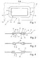
In Figur 1 ist ein Flächengebilde in Form einer Laderaumabdeckung 11 aus einem flexiblen, insbesondere textilen, Werkstoff teilweise dargestellt. Die Laderaumabdeckung 11 ist zur Abdeckung eines Laderaumes vorgesehen, der sich von einer Rückseite einer Rückenlehnenanordnung einer Fondsitzbank bis zur Heckklappe eines Fahrzeuges erstreckt. Die Laderaumabdeckung 11 wird aus einer Ruheposition, in der ein flexibles Flächengebilde auf einer Rollowelle aufgewickelt ist, in eine Funktionsposition zum Abdecken des Laderaumes übergeführt, wobei die Laderaumabdeckung 11 an Halterungen eingehängt wird. An einer vorderen Stirnseite der Laderaumabdeckung 11 ist ein formsteifes Konturteil 12 vorgesehen, welches eine Durchgriffsöffnung 14 aufweist. Die Durchgriffsöffnung 14 ist von einem Rahmen 16 umgeben, der aus einem oberen Rahmenteil 17 und einem unteren Rahmenteil 18 (Figur 2) besteht. Eine durch den Rahmen 16 begrenzte Durchgriffsfläche 19 ist durch ein Abdeckelement 21 verdeckt, welches in einer Schließposition 22 angeordnet ist.In Figure 1, a sheet in the form of a
In Figur 2 ist eine Schnittdarstellung entlang der Linie I-I gemäß Figur 1 dargestellt. Das obere und untere Rahmenteil 17, 18 sind bevorzugt durch eine Steck- und Rastverbindung 24 miteinander verbunden und greifen im Randbereich der Durchgriffsöffnung 14 an dem Konturteil 12 an.FIG. 2 shows a sectional view along the line I-I according to FIG. The upper and
Das Abdeckelement 21 ist über einen biegeelastischen Bereich 26 mit dem oberen Rahmenteil 17 verbunden und entlang einer Schwenkachse 27 (Figur 1) gemäß Pfeil a nach unten schwenkbar gelagert. Der biegeelastische Bereich 26 ist beispielsweise als Filmscharnier ausgebildet. Diesem Bereich 26 gegenüberliegend ist an dem Abdeckelement 21 eine Anschlagfläche 29 vorgesehen, welche sich bevorzugt über die gesamte Länge des Rahmenabschnitts 31 erstreckt. Alternativ kann vorgesehen sein, dass die Anschlagfläche 29 auch entlang den seitlichen Rahmenabschnitten bis zur Schwenkachse 27 ausgebildet ist. Dadurch ist das Einnehmen einer definierten Schließposition 22 gegeben. Zusätzlich kann die Durchgriffsfläche 19 vollständig verschlossen sein.The
Im Ausführungsbeispiel gemäß Figur 2 greift die Anschlagfläche 29 an dem oberen Rahmenteil 17 an. An dem unteren Rahmenteil 18 dem biegeelastischen Bereich 26 zugeordnet sind Rückstellmittel 33 vorgesehen. Nach dem Herausnehmen der Finger einer Hand aus der Durchgriffsöffnung 14 bzw. der Durchgriffsfläche 19 wird das Abdeckelement 21 aus einer nicht näher dargestellten Auslenkposition durch die Rückstellmittel 33 unterstützt in die Schließposition 22 gemäß Pfeil b übergeführt und in dieser gehalten. Die Rückstellmittel 33 können beispielsweise an das untere Rahmenteil 18 angespritzt sein, so dass in einem Arbeitsschritt die Rückstellmittel 33 und das Rahmenteil 18 hergestellt sind. Alternativ kann das Rückstellmittel 33 durch eine lösbare oder unlösbare Verbindung zum Rahmenteil 18, zum Abdeckelement 21 und/oder zum biegeelastischen Bereich 26 angeordnet sein. Das Rückstellmittel 33 erstreckt sich durchgehend oder abschnittsweise entlang der Schwenkachse. Das Rückstellmittel 33 verjüngt sich vorteilhafterweise im Querschnitt zur freien auslenkbaren Kante des Abdeckelementes 21.In the embodiment according to FIG. 2, the
In Figur 3 ist eine alternative Ausführungsform der Erfindung zu den Figuren 1 und 2 dargestellt. In diesem Ausführungsbeispiel greift die an dem Abdeckelement 21 angeordnete Anschlagfläche 29 an dem unteren Rahmenteil 18 an. Der biegeelastische Bereich 26 ist an dem unteren Rahmenteil 18 vorgesehen. Dieser biegeelastische Bereich 26 umfasst gleichzeitig die Rückstellmittel 33, so dass beim Eingriff in die Durchgriffsfläche 19 und dem Überführen des Abdeckelementes 21 in die Auslenkposition gemäß Pfeil a gleichzeitig Rückstellkräfte aufgebaut werden, die das Abdeckelement 21 selbstständig in eine Schließposition 22 gemäß Pfeil b zurücksetzen.FIG. 3 shows an alternative embodiment of the invention to FIGS. 1 and 2. In this embodiment, the arranged on the
Bevorzugt ist eine Oberfläche 36 in der Kontur an das obere Rahmenteil angepasst, so dass in einer Schließposition 22 des Abdeckelementes 21 eine geschlossene Oberfläche mit dem oberen Rahmenteil 17 gebildet ist. Der biegeelastische Bereich 26 kann auch an dem oberen Rahmenteil 17 angreifen.Preferably, a
In Figur 4 ist eine weitere alternative Ausführungsform eines erfindungsgemäßen Flächengebildes entlang der Schnittlinie I-I in Figur 1 dargestellt. In diesem Ausführungsbeispiel ist das Abdeckelement 21 selbst zumindest teilweise als biegeelastischer Bereich ausgebildet und geht unmittelbar in einen Abschnitt des unteren Rahmenteils 18 über. Somit kann ein zur Anschlagfläche 26 weisender Bereich und/oder ein Übergangsbereich zum Rahmenteil 18 biegeelastisch ausgebildet sein. Über eine Anschlagfläche 26 greift das Abdeckelement 21 an dem Rahmenteil 18 an. Bevorzugt ist bei dieser Ausführungsform vorgesehen, dass die Rückstellmittel 33, welche durch die Ausbildung der Kontur im Übergangsbereich zwischen dem Rahmenteil 18 und dem Abdeckelement 21 integriert sind, eine Vorspannung aufweisen, so dass nach dem Auslenken des Abdeckelementes 21 ein selbständiges Zurücksetzen sichergestellt ist. Die Rückstellmittel 33 können gemäß der Darstellung integriert sein. Ebenfalls können streifen- oder rippenförmige Versteifungen auf einer Unterseite des Abdeckelementes 21 vorgesehen sein. Der obere Rahmen 17 weist vorteilhafterweise einen umlaufenden Bund 37 auf, welcher den Rahmen 16 zur Durchgriffsfläche 19 schließt.FIG. 4 shows a further alternative embodiment of a fabric according to the invention along the section line II in FIG. In this exemplary embodiment, the
In Figur 5 ist eine schematische Draufsicht auf eine alternative erfindungsgemäße Ausgestaltung eines Flächengebildes gegeben. Die Durchgriffsfläche 14 ist durch zwei Abdeckelemente 21 verschlossen, welche nach einer ersten Ausführungsform gleichlange Schenkel umfassen, deren Stirnseiten 41, 42 durch zwei parallel verlaufende Kanten ausgebildet sind. Alternativ kann vorgesehen sein, dass die Abdeckelemente 21 unterschiedlich lang ausgebildet sind. Des Weiteren kann alternativ vorgesehen sein, dass die stirnseitigen Kanten 41, 42 einen wellenförmigen oder zickzackförmigen Verlauf aufweisen. Ebenso kann alternativ vorgesehen sein, dass diese stirnseitigen Kanten 41, 42 sich zumindest teilweise und/oder abschnittsweise überlappen. Des Weiteren kann alternativ vorgesehen sein, dass mehrere Abdeckelemente 21 die Durchgriffsöffnung 14 verschließen.FIG. 5 shows a schematic plan view of an alternative embodiment of a fabric according to the invention. The
In Figur 6 ist eine schematische Schnittdarstellung entlang der Linie V-V in Figur 5 dargestellt. Die Abdeckelemente 21 weisen einen Randbereich 44 auf, der durch eine lösbare oder unlösbare Verbindung mit einer Unterseite am Rahmenteil 17 vorgesehen ist. Ebenso kann der Randbereich 44 auch auf der Außenseite oder Innenseite am unteren Rahmenteil vorgesehen sein. Die Randbereiche 41 können alternativ auch über die Rastverbindungen 21 zum Rahmenteil 17 oder 18 befestigt sein. Bevorzugt sind die Abdeckelemente 21 im vorderen Bereich nahe den stirnseitigen Kanten 41, 42 biegeelastischer ausgebildet als im Bereich nahe dem Rahmenteil 17, 18. Bei dieser Ausführungsform ist eine Durchgriffsmöglichkeit sowohl von einer Oberseite als auch einer Unterseite gegeben. Die Rückstellmittel 33 sind bevorzugt im Übergangsbereich zwischen dem Rahmen 16 und einer freien Schenkellänge des Abdeckelementes 21 integriert oder können durch separate an der Unterseite des Abdeckelementes 21 oder dem Rahmenteil 18 angeordnete elastische Rückstellmittel 33 ausgebildet sein. Beispielsweise kann ein gummielastisches Rückstellmittel 33 an dem Rahmenteil 18 angreifen, um bei einer Auslenkung der stirnseitigen Kante 41 nach unten das Abdeckelement 21 in eine Schließposition 22 überzuführen. Des Weiteren kann vorgesehen sein, dass die stirnseitigen Kanten 41, 42 zwei zueinander komplementär ausgebildete Anschlagflächen aufweisen, um eine definierte Schließposition 22 einzunehmen.FIG. 6 shows a schematic sectional illustration along the line VV in FIG. The
In Figur 7 ist eine schematische Schnittdarstellung entlang der Linie V-V in Figur 5 einer weiteren erfindungsgemäßen Ausgestaltung dargestellt. Die Abdeckelemente 21 können in einem Ein- oder Mehrkomponenten-Spritzgussverfahren an dem Rahmen 18 angespritzt sein. Alternativ kann vorgesehen sein, dass die Abdeckelemente 21 separat zum Rahmenteil 17, 18 hergestellt werden und durch eine Steckverbindung zum Rahmenteil 17 oder 18 fixiert werden. Die Steckverbindung kann durch Schnapp- oder Rastelemente ausgebildet sein oder in Form von Vertiefungen und Wülsten, die ein erschwertes Abziehen der Abdeckelemente 21 vom Rahmenteil 17 oder 18 bewirken. Ebenso kann eine Klebe- oder Schweißverbindung vorgesehen sein. Die Rückstellmittel 33 können beispielsweise als keilförmige Stützen an der Unterseite des Abdeckelementes 21 angreifen.FIG. 7 shows a schematic sectional illustration along the line V-V in FIG. 5 of a further embodiment according to the invention. The
Zur Herstellung des Rahmens 16 werden bevorzugt spritzgussfähige Materialien eingesetzt, wie PA, PP oder dergleichen. Zur Herstellung der biegeelastischen Bereiche werden beispielsweise Materialien wie TEE, TPE oder dergleichen eingesetzt, die eine Shorehärte von beispielsweise 50 bis 80 Shore aufweisen.For the production of the
Es versteht sich, dass die einzelnen zu den jeweiligen Ausführungsbeispielen beschriebenen Merkmale jeweils für sich erfindungswesentlich sind und beliebig miteinander kombinierbar sind.It is understood that the individual features described in relation to the respective exemplary embodiments in each case are essential to the invention and can be combined with one another as desired.
Claims (15)
- Planar form, especially a vehicle luggage compartment cover, with a reach-through opening (14) which can at least be partially closed by a covering element (21) which is movable between at least one deflecting position releasing the reach-through opening (14) and a closing position covering the reach-through opening (14), characterized in that the at least one covering element (21) comprises a flexible area (26).
- Planar form according to claim 1, characterized in that the at least one covering element (21) is allocated to a frame (16) of a thermoplastic or duroplastic material which at least partially surrounds the reach-through opening (14).
- Planar form according to claim 1 or 2, characterized in that the at least one covering element (21) is designed at least partially flexibly in the area of a free reach-through opening (19).
- Planar form according to any one of the preceding claims, characterized in that the at least one covering element (21) comprises a frame (16) at least partially surrounding the reach-through opening (14) and being provided by a detachable or permanent connection on the frame (16).
- Planar form according to claim 1, characterized in that the at least one covering element (21) and a frame (16) at least partially surrounding the reach-through opening (14) are connected with each other by a flexible area (26).
- Planar form according to claim 5, characterized in that the flexible area (26) is designed as a joint connection, especially as a film hinge.
- Planar form according to any one of the preceding claims, characterized in that the at least one covering element (21) is connected with a top or bottom frame part (17, 18) of the frame (16).
- Planar form according to any one of the preceding claims, characterized in that the at least one covering element (21) is held with at least one reset means (33) in a closing position (22) which is provided at least on the frame (16), the flexible area (26) or the covering element (21).
- Planar form according to claim 8, characterized in that the reset means (33) is manufactured of a flexible material which is at least molded, arranged by an adhesive-, fusion-, clamping- or plug-connection on the covering element (21), the frame (16) or the flexible area (26).
- Planar form according to claim 8 or 9, characterized in that the reset means (33) has a hardness of 50 to 80 Shore.
- Planar form according to any one of the preceding claims, characterized in that the at least one covering element (21) and the frame (16) at least partially surrounding the reach-through opening (14) is formed as an injection molded part.
- Planar form according to any one of the preceding claims, characterized in that the at least one covering element (21) and the frame (16) at least partially surrounding the reach-through opening (14) are manufactured by a single- or multicomponent injection molding method.
- Planar form according to any one of the preceding claims, characterized in that at least one top side of the covering element (21) or the frame (16) comprises a coating which is equivalent to that which is adjacent to the reach-through opening (14).
- Planar form according to claim 13, characterized in that the surface of the at least one covering element (21) or the frame (16) is varnished or comprises a foil or planar material corresponding to the planar form.
- Planar form according to any one of the preceding claims, characterized in that the covering element (21) connected with a frame part (17, 18) is fastened with another frame part (18, 17) by means of a detachable or permanent connection to the reach-through opening (14).
Applications Claiming Priority (2)
| Application Number | Priority Date | Filing Date | Title |
|---|---|---|---|
| DE200420007744 DE202004007744U1 (en) | 2004-05-11 | 2004-05-11 | Flat cover for a luggage compartment cover of a motor vehicle |
| DE202004007744U | 2004-05-11 |
Publications (2)
| Publication Number | Publication Date |
|---|---|
| EP1595746A1 EP1595746A1 (en) | 2005-11-16 |
| EP1595746B1 true EP1595746B1 (en) | 2007-06-06 |
Family
ID=34936331
Family Applications (1)
| Application Number | Title | Priority Date | Filing Date |
|---|---|---|---|
| EP20050010117 Expired - Fee Related EP1595746B1 (en) | 2004-05-11 | 2005-05-10 | Vehicle luggage compartment cover |
Country Status (2)
| Country | Link |
|---|---|
| EP (1) | EP1595746B1 (en) |
| DE (2) | DE202004007744U1 (en) |
Cited By (1)
| Publication number | Priority date | Publication date | Assignee | Title |
|---|---|---|---|---|
| WO2009156686A1 (en) * | 2008-06-27 | 2009-12-30 | Renault S.A.S. | Load space cover device with an improved pull handle |
Families Citing this family (6)
| Publication number | Priority date | Publication date | Assignee | Title |
|---|---|---|---|---|
| DE102007041147B4 (en) * | 2007-08-30 | 2016-02-18 | Audi Ag | Cover for a load compartment floor |
| DE102008058361A1 (en) * | 2008-11-20 | 2010-05-27 | GM Global Technology Operations, Inc., Detroit | Cargo floor handle |
| DE102009055836A1 (en) * | 2009-11-26 | 2011-06-01 | GM Global Technology Operations LLC, ( n. d. Ges. d. Staates Delaware ), Detroit | Pivotable plate for use in motor vehicle, has upper side and lower side, at which gripping unit is provided, where gripping unit has hand grip that is available at upper side |
| DE102013012088B3 (en) * | 2013-07-22 | 2014-06-18 | Macauto Industrial Co., Ltd. | Load compartment cover for motor vehicle e.g. motor car, has cover element held in rest position by spring element for providing passage aperture in closed position and pivoted for engagement with passage aperture in open position |
| FR3011786A1 (en) * | 2013-10-15 | 2015-04-17 | Cera | AUTOMOTIVE VEHICLE LUGGAGE COMPARTMENT REPAIR SYSTEM |
| ES2893245B2 (en) * | 2020-07-29 | 2022-06-06 | Seat Sa | Cargo floor of the trunk of a vehicle |
Family Cites Families (3)
| Publication number | Priority date | Publication date | Assignee | Title |
|---|---|---|---|---|
| DE19707676C1 (en) | 1997-02-26 | 1998-02-26 | Butz Peter Verwaltung | Storage space cover for combination motor car |
| DE10218838C1 (en) | 2002-04-23 | 2003-09-25 | Bos Gmbh | Automobile trunk space cover for hatchback vehicle has access opening provided with pivoted cover element |
| DE20217717U1 (en) * | 2002-11-08 | 2003-01-16 | Bos Gmbh | Luggage space cover with an operation opening and a flap for motor vehicles, in particular, estate cars comprises at least one damping element which slows down the return motion of the flap |
-
2004
- 2004-05-11 DE DE200420007744 patent/DE202004007744U1/en not_active Expired - Lifetime
-
2005
- 2005-05-10 EP EP20050010117 patent/EP1595746B1/en not_active Expired - Fee Related
- 2005-05-10 DE DE200550000801 patent/DE502005000801D1/en active Active
Cited By (2)
| Publication number | Priority date | Publication date | Assignee | Title |
|---|---|---|---|---|
| WO2009156686A1 (en) * | 2008-06-27 | 2009-12-30 | Renault S.A.S. | Load space cover device with an improved pull handle |
| FR2933052A1 (en) * | 2008-06-27 | 2010-01-01 | Renault Sas | LUGGAGE DEVICE HAVING AN IMPROVED DRAWING HANDLE |
Also Published As
| Publication number | Publication date |
|---|---|
| DE202004007744U1 (en) | 2005-09-29 |
| EP1595746A1 (en) | 2005-11-16 |
| DE502005000801D1 (en) | 2007-07-19 |
Similar Documents
| Publication | Publication Date | Title |
|---|---|---|
| EP1595746B1 (en) | Vehicle luggage compartment cover | |
| DE102006041734B4 (en) | Device for fastening an airbag unit in an assembly of a motor vehicle, in particular in a steering wheel, by latching | |
| EP2621673B1 (en) | Telescopic protective covering | |
| DE102005056662B4 (en) | Device for attaching a roof rack | |
| EP2083666B1 (en) | Folding flat mop comprising a trapezoidal mop plate | |
| DE102016007854A1 (en) | Roller blind and cradle with roller blind | |
| WO2008031428A1 (en) | Wind deflector for a retractable vehicle roof | |
| EP0610838B1 (en) | Floor wiper | |
| DE102012000173A1 (en) | Air flap arrangement for motor vehicle front end, has air flaps opened or closed over actuator and coupled with linear drive over thrust device such that air flaps are guided on two sides in link guides in vehicle transverse direction | |
| DE19707676C1 (en) | Storage space cover for combination motor car | |
| DE102009011481A1 (en) | Fastening device and fastening device for fastening an airbag to a vehicle structure | |
| EP1591317B1 (en) | Cover for storage compartment | |
| EP2334512B1 (en) | Mirror element | |
| DE19648330B4 (en) | Automotive body | |
| EP1348585B1 (en) | Displaceable panel for vehicle roof and sliding roof module | |
| DE102016213765A1 (en) | Door handle device | |
| EP3287325B1 (en) | Motor vehicle and fixing device for a motor vehicle | |
| EP0968882A1 (en) | Flip cap closure | |
| DE102005032564B4 (en) | Frame arrangement for the displaceable mounting of an openable vehicle roof part | |
| DE10312286B4 (en) | Modular wind deflector for a sunroof | |
| WO2018184910A1 (en) | Sunroof wind deflector element of a motor vehicle, and wind deflector | |
| EP0745509B1 (en) | Upholstered body, in particular for motor vehicle headrests | |
| DE19755592B4 (en) | Locking device for curved lid | |
| DE102008000005A1 (en) | Wind deflector with synchronized double joint | |
| EP1431113B1 (en) | Profiled part to hold and stiffen an overlapping section in a flat item |
Legal Events
| Date | Code | Title | Description |
|---|---|---|---|
| PUAI | Public reference made under article 153(3) epc to a published international application that has entered the european phase |
Free format text: ORIGINAL CODE: 0009012 |
|
| AK | Designated contracting states |
Kind code of ref document: A1 Designated state(s): AT BE BG CH CY CZ DE DK EE ES FI FR GB GR HU IE IS IT LI LT LU MC NL PL PT RO SE SI SK TR |
|
| AX | Request for extension of the european patent |
Extension state: AL BA HR LV MK YU |
|
| RAP1 | Party data changed (applicant data changed or rights of an application transferred) |
Owner name: REUM GMBH & CO. BETRIEBS KG |
|
| 17P | Request for examination filed |
Effective date: 20060516 |
|
| AKX | Designation fees paid |
Designated state(s): DE FR IT SE |
|
| GRAP | Despatch of communication of intention to grant a patent |
Free format text: ORIGINAL CODE: EPIDOSNIGR1 |
|
| GRAS | Grant fee paid |
Free format text: ORIGINAL CODE: EPIDOSNIGR3 |
|
| GRAA | (expected) grant |
Free format text: ORIGINAL CODE: 0009210 |
|
| AK | Designated contracting states |
Kind code of ref document: B1 Designated state(s): DE FR IT SE |
|
| RTI1 | Title (correction) |
Free format text: VEHICLE LUGGAGE COMPARTMENT COVER |
|
| REF | Corresponds to: |
Ref document number: 502005000801 Country of ref document: DE Date of ref document: 20070719 Kind code of ref document: P |
|
| REG | Reference to a national code |
Ref country code: SE Ref legal event code: TRGR |
|
| ET | Fr: translation filed | ||
| PLBE | No opposition filed within time limit |
Free format text: ORIGINAL CODE: 0009261 |
|
| STAA | Information on the status of an ep patent application or granted ep patent |
Free format text: STATUS: NO OPPOSITION FILED WITHIN TIME LIMIT |
|
| 26N | No opposition filed |
Effective date: 20080307 |
|
| REG | Reference to a national code |
Ref country code: FR Ref legal event code: PLFP Year of fee payment: 11 |
|
| REG | Reference to a national code |
Ref country code: DE Ref legal event code: R081 Ref document number: 502005000801 Country of ref document: DE Owner name: BOS GMBH & CO. KG, DE Free format text: FORMER OWNER: REUM GMBH & CO. BETRIEBS KG, 74736 HARDHEIM, DE Ref country code: DE Ref legal event code: R082 Ref document number: 502005000801 Country of ref document: DE Representative=s name: PATENTANWAELTE RUFF, WILHELM, BEIER, DAUSTER &, DE Ref country code: DE Ref legal event code: R082 Ref document number: 502005000801 Country of ref document: DE Representative=s name: PATENTANWAELTE OSTRIGA, SONNET, WIRTHS & VORWE, DE Ref country code: DE Ref legal event code: R081 Ref document number: 502005000801 Country of ref document: DE Owner name: GRAMMER INTERIOR COMPONENTS GMBH, DE Free format text: FORMER OWNER: REUM GMBH & CO. BETRIEBS KG, 74736 HARDHEIM, DE Ref country code: DE Ref legal event code: R082 Ref document number: 502005000801 Country of ref document: DE Representative=s name: MAMMEL & MASER, DE Ref country code: DE Ref legal event code: R081 Ref document number: 502005000801 Country of ref document: DE Owner name: REUM KUNSTSTOFF- UND METALLTECHNIK GMBH, DE Free format text: FORMER OWNER: REUM GMBH & CO. BETRIEBS KG, 74736 HARDHEIM, DE |
|
| REG | Reference to a national code |
Ref country code: FR Ref legal event code: CD Owner name: REUM KUNSTSTOFF- UND METALLTECHNIK GMBH, DE Effective date: 20160215 Ref country code: FR Ref legal event code: TP Owner name: REUM KUNSTSTOFF- UND METALLTECHNIK GMBH, DE Effective date: 20160215 |
|
| REG | Reference to a national code |
Ref country code: FR Ref legal event code: PLFP Year of fee payment: 12 |
|
| REG | Reference to a national code |
Ref country code: DE Ref legal event code: R082 Ref document number: 502005000801 Country of ref document: DE Representative=s name: PATENTANWAELTE RUFF, WILHELM, BEIER, DAUSTER &, DE Ref country code: DE Ref legal event code: R082 Ref document number: 502005000801 Country of ref document: DE Representative=s name: PATENTANWAELTE OSTRIGA, SONNET, WIRTHS & VORWE, DE |
|
| REG | Reference to a national code |
Ref country code: DE Ref legal event code: R081 Ref document number: 502005000801 Country of ref document: DE Owner name: BOS GMBH & CO. KG, DE Free format text: FORMER OWNER: REUM KUNSTSTOFF- UND METALLTECHNIK GMBH, 74736 HARDHEIM, DE Ref country code: DE Ref legal event code: R082 Ref document number: 502005000801 Country of ref document: DE Representative=s name: PATENTANWAELTE RUFF, WILHELM, BEIER, DAUSTER &, DE Ref country code: DE Ref legal event code: R082 Ref document number: 502005000801 Country of ref document: DE Representative=s name: PATENTANWAELTE OSTRIGA, SONNET, WIRTHS & VORWE, DE Ref country code: DE Ref legal event code: R081 Ref document number: 502005000801 Country of ref document: DE Owner name: GRAMMER INTERIOR COMPONENTS GMBH, DE Free format text: FORMER OWNER: REUM KUNSTSTOFF- UND METALLTECHNIK GMBH, 74736 HARDHEIM, DE |
|
| REG | Reference to a national code |
Ref country code: FR Ref legal event code: PLFP Year of fee payment: 13 |
|
| REG | Reference to a national code |
Ref country code: DE Ref legal event code: R082 Ref document number: 502005000801 Country of ref document: DE Representative=s name: PATENTANWAELTE RUFF, WILHELM, BEIER, DAUSTER &, DE Ref country code: DE Ref legal event code: R081 Ref document number: 502005000801 Country of ref document: DE Owner name: BOS GMBH & CO. KG, DE Free format text: FORMER OWNER: GRAMMER INTERIOR COMPONENTS GMBH, 74736 HARDHEIM, DE |
|
| PGFP | Annual fee paid to national office [announced via postgrant information from national office to epo] |
Ref country code: FR Payment date: 20170522 Year of fee payment: 13 |
|
| REG | Reference to a national code |
Ref country code: FR Ref legal event code: CD Owner name: GRAMMER INTERIOR COMPONENTS GMBH, DE Effective date: 20170725 |
|
| PGFP | Annual fee paid to national office [announced via postgrant information from national office to epo] |
Ref country code: IT Payment date: 20170524 Year of fee payment: 13 Ref country code: SE Payment date: 20170523 Year of fee payment: 13 |
|
| REG | Reference to a national code |
Ref country code: FR Ref legal event code: TP Owner name: BOS GMBH & CO, KG, DE Effective date: 20180619 |
|
| PGFP | Annual fee paid to national office [announced via postgrant information from national office to epo] |
Ref country code: DE Payment date: 20180529 Year of fee payment: 14 |
|
| REG | Reference to a national code |
Ref country code: SE Ref legal event code: EUG |
|
| PG25 | Lapsed in a contracting state [announced via postgrant information from national office to epo] |
Ref country code: SE Free format text: LAPSE BECAUSE OF NON-PAYMENT OF DUE FEES Effective date: 20180511 |
|
| PG25 | Lapsed in a contracting state [announced via postgrant information from national office to epo] |
Ref country code: FR Free format text: LAPSE BECAUSE OF NON-PAYMENT OF DUE FEES Effective date: 20180531 Ref country code: IT Free format text: LAPSE BECAUSE OF NON-PAYMENT OF DUE FEES Effective date: 20180510 |
|
| REG | Reference to a national code |
Ref country code: DE Ref legal event code: R119 Ref document number: 502005000801 Country of ref document: DE |
|
| PG25 | Lapsed in a contracting state [announced via postgrant information from national office to epo] |
Ref country code: DE Free format text: LAPSE BECAUSE OF NON-PAYMENT OF DUE FEES Effective date: 20191203 |