EP1595687A1 - Verfahren und Vorrichtung zur Herstellung eines faserverstärkten Bauteils - Google Patents
Verfahren und Vorrichtung zur Herstellung eines faserverstärkten Bauteils Download PDFInfo
- Publication number
- EP1595687A1 EP1595687A1 EP04008931A EP04008931A EP1595687A1 EP 1595687 A1 EP1595687 A1 EP 1595687A1 EP 04008931 A EP04008931 A EP 04008931A EP 04008931 A EP04008931 A EP 04008931A EP 1595687 A1 EP1595687 A1 EP 1595687A1
- Authority
- EP
- European Patent Office
- Prior art keywords
- fibers
- mold cavity
- fiber
- fiber bundle
- cavity
- Prior art date
- Legal status (The legal status is an assumption and is not a legal conclusion. Google has not performed a legal analysis and makes no representation as to the accuracy of the status listed.)
- Granted
Links
Images




Classifications
-
- B—PERFORMING OPERATIONS; TRANSPORTING
- B29—WORKING OF PLASTICS; WORKING OF SUBSTANCES IN A PLASTIC STATE IN GENERAL
- B29C—SHAPING OR JOINING OF PLASTICS; SHAPING OF MATERIAL IN A PLASTIC STATE, NOT OTHERWISE PROVIDED FOR; AFTER-TREATMENT OF THE SHAPED PRODUCTS, e.g. REPAIRING
- B29C70/00—Shaping composites, i.e. plastics material comprising reinforcements, fillers or preformed parts, e.g. inserts
- B29C70/04—Shaping composites, i.e. plastics material comprising reinforcements, fillers or preformed parts, e.g. inserts comprising reinforcements only, e.g. self-reinforcing plastics
- B29C70/28—Shaping operations therefor
- B29C70/40—Shaping or impregnating by compression not applied
- B29C70/42—Shaping or impregnating by compression not applied for producing articles of definite length, i.e. discrete articles
- B29C70/44—Shaping or impregnating by compression not applied for producing articles of definite length, i.e. discrete articles using isostatic pressure, e.g. pressure difference-moulding, vacuum bag-moulding, autoclave-moulding or expanding rubber-moulding
- B29C70/446—Moulding structures having an axis of symmetry or at least one channel, e.g. tubular structures, frames
-
- B—PERFORMING OPERATIONS; TRANSPORTING
- B29—WORKING OF PLASTICS; WORKING OF SUBSTANCES IN A PLASTIC STATE IN GENERAL
- B29C—SHAPING OR JOINING OF PLASTICS; SHAPING OF MATERIAL IN A PLASTIC STATE, NOT OTHERWISE PROVIDED FOR; AFTER-TREATMENT OF THE SHAPED PRODUCTS, e.g. REPAIRING
- B29C70/00—Shaping composites, i.e. plastics material comprising reinforcements, fillers or preformed parts, e.g. inserts
- B29C70/04—Shaping composites, i.e. plastics material comprising reinforcements, fillers or preformed parts, e.g. inserts comprising reinforcements only, e.g. self-reinforcing plastics
- B29C70/28—Shaping operations therefor
- B29C70/40—Shaping or impregnating by compression not applied
- B29C70/42—Shaping or impregnating by compression not applied for producing articles of definite length, i.e. discrete articles
- B29C70/46—Shaping or impregnating by compression not applied for producing articles of definite length, i.e. discrete articles using matched moulds, e.g. for deforming sheet moulding compounds [SMC] or prepregs
- B29C70/462—Moulding structures having an axis of symmetry or at least one channel, e.g. tubular structures, frames
-
- B—PERFORMING OPERATIONS; TRANSPORTING
- B29—WORKING OF PLASTICS; WORKING OF SUBSTANCES IN A PLASTIC STATE IN GENERAL
- B29C—SHAPING OR JOINING OF PLASTICS; SHAPING OF MATERIAL IN A PLASTIC STATE, NOT OTHERWISE PROVIDED FOR; AFTER-TREATMENT OF THE SHAPED PRODUCTS, e.g. REPAIRING
- B29C70/00—Shaping composites, i.e. plastics material comprising reinforcements, fillers or preformed parts, e.g. inserts
- B29C70/04—Shaping composites, i.e. plastics material comprising reinforcements, fillers or preformed parts, e.g. inserts comprising reinforcements only, e.g. self-reinforcing plastics
- B29C70/28—Shaping operations therefor
- B29C70/54—Component parts, details or accessories; Auxiliary operations, e.g. feeding or storage of prepregs or SMC after impregnation or during ageing
- B29C70/543—Fixing the position or configuration of fibrous reinforcements before or during moulding
Definitions
- the invention relates to a method and a device for Production of a fiber-reinforced rotationally symmetric rod-shaped component.
- the fiber reinforcement material is expediently of fibers coated with a matrix material.
- DE 4 335 557 C1 discloses a process for the production of components made of silicon carbide reinforced titanium alloys described. Here are the with the metallic matrix material coated single fibers in a mold cavity pressed.
- DE 19 811 397 C1 describes a device in which a rotationally symmetrical tubular workpiece with fibers is occupied, which surround either the workpiece helically or extend in the longitudinal direction.
- the fibers are from one Wrapped in matrix material. After attaching the fiber layers on The workpiece will make the workpiece a hot isostatic Pressing process in which the matrix materials connect the fibers.
- pipes can be made which are mechanically and thermally highly resilient.
- Such Tubes are suitable, for example, for drive shafts in Lightweight construction, as structural components for the transmission of forces or as piping for conveying gaseous or liquid media or as a pressure vessel, carrier or cylinder.
- the invention is based on the object, a method and a device for producing a fiber-reinforced rotationally symmetric Specify rod-shaped component to a Simplification of the manufacturing process with simultaneous Improvement of the structural properties of the component too to reach.
- a fiber bundle of numerous fibers in introduced an elongated mold cavity, wherein the fibers initially aligned axially to the mold cavity. Thereafter, a helical twisting of the fiber bundle takes place while reducing the axial distance of the ends of the Fiber bundle, whereby the lateral distances of the fibers reduced become. This is followed by isostatic pressing the fibers together with a matrix material in the Mold cavity.
- the fibers are preferably initially in axial alignment placed vertically so that they rise freely and Align vertically without external constraint.
- the fiber bundle is thus a precompacting exposed.
- all located in the component Fibers in a single pass at the desired angle aligned. This is achieved by exploiting the inclination the fiber, a compressive stress due to lateral tilting dodge.
- the tilting of the fibers in the desired position by tangential relative movement of the pressure transmission elements supported at the fiber ends.
- the fibers are first by the helical deformation of the fiber bundle together approximated and possibly brought into mutual contact.
- the pre-compacted fiber bundle during this process the isostatic pressing process preferably under additional Heat action pressed.
- a fiber material are particularly suitable fibers of ceramic, metal, polymer, carbon or glass with a diameter between 4 and 500 .mu.m and a length which corresponds to at least 100 times the diameter.
- the fibers are embedded in a matrix.
- This may be a polymer, metal or a ceramic.
- the matrix material is pressed together with the fibers in the isostatic pressing process to the component.
- the matrix material is preferably high melting point metals such as iron, titanium and nickel alloys. A combination of silicon carbide fibers with a titanium alloy matrix material has proved to be particularly favorable.
- the reduction of the lateral fiber distance during the helical twisting of the fiber bundle has the advantage that the fibers only in the final position of a forced contact subject. This will cause the friction between the fibers and thus the power to carry out the process low held. This is for effective implementation and for Protection against fiber damage of importance, since first the Fibers with a lower packing density introduced into the mold cavity become. Besides being able to use fibers, which are coated with a matrix material, can also fibers processed without matrix material. Here is the Matrix material or filler material only after the Feature b injected into the mold cavity.
- the fibers are loose at their ends in annular gaps guided.
- the annular gaps cause a local definition the fiber ends, but allow the pivoting of the fibers to the respective fiber end around, so that the fiber at an angle can set freely.
- a retaining ring is one end of the fiber bundle holds, in a combination of translation and rotation moved relative to the mold cavity.
- the procedure can with a Computer-controlled device are executed, which the Executes rotational and translational movements programmatically.
- a guide device is made of interlocking Guide elements on a guide part for the retaining ring and the retaining ring possible, the coordination the two types of movement takes place in the manner of a link control.
- the invention enables the production of rod-shaped components with helical fiber reinforcement.
- Tubular Components can be pipes or rods. It also exists the possibility of such components, the opposing fiber reinforcements contained in each other and to each other connect.
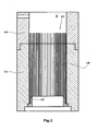
- FIGS. 1-6 is a mold 10th provided, which has an upright cylindrical outer shell 11, which is open at both ends.
- a retaining ring 12 is screwed in, with between the wall of the retaining ring 12 and the inner surface of the outer shell 11 an annular gap 13, in which the lower ends of the Fibers are used.
- the outer jacket 11 is at his upper end by a screwed cylindrical guide part 14 extended.
- the guide member 14 has radial bores 15 for pin-shaped guide elements.
- the inner surfaces of outer jacket 11 and guide member 14 are von. Sammlungem diameter and escapes with each other.
- the outer jacket 11 limits the Mold cavity 16.
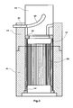
- Fig. 2 shows the state that in the mold cavity 16, a fiber bundle 17 of numerous parallel and equal length fibers 18 has been introduced.
- the lower ends of the fibers 18 sit in the annular gap 13. From there the fibers protrude perpendicularly, forming an annular fiber bundle.
- the fibers 18 are made of high temperature resistant ceramic, in particular of silicon carbide.
- the fibers are all the same predetermined length and coated with matrix material.
- the fiber diameter is 140 ⁇ m
- the matrix coating consists of a titanium alloy, particularly Ti-6A1-4V with a thickness of 30 ⁇ m. This results in an overall diameter of the matrix-coated fiber of 200 ⁇ m.
- the fibers have the required bending stiffness, so that they freely assume a nearly axial alignment.
- the fibers are in front of the Insertion in the mold cavity (16) by auxiliary fibers or a Binders are fixed relative to each other, such that the fibers (18) their angular mobility and thus their free Maintaining adjustability.
- the upper retaining ring is in the guide member 14 20 used, which also with the inner surface of the outer shell 11 and the guide member 14 forms an annular gap 21.
- the upper ends of the fibers 18 protrude into the guide part 14 into it.
- the upper retaining ring 20 thus becomes so in the guide part 14 inserted that the upper fiber ends of the Annular gap 21 can be recorded.
- a Stamp 22 attached on the retaining ring 20.
- This has on its peripheral surface trained guide elements 23, which with guide elements 24 of the guide member 14 cooperate.
- the guide elements 23 are grooves and the guide elements 24 are pins, which are inserted into the holes 15 and out of these protrude into the grooves.
- the guide elements 23 and 24 act in the way together that an axial movement of the punch 22nd causes a simultaneous rotational movement of the punch.
- the retaining ring 20 is both translational as well as rotating at the same time.
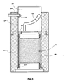
- that the fiber bundle 17 is deformed helically, as this is shown in Fig. 4.
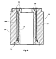
- FIG. 5 is for fixing the upper retaining ring 20 in With respect to the lower retaining ring 12 with respect to the outer shell 11 a guide sleeve 28 in the annular fiber bundle 17th used and bolted to the retaining ring 20.
- the inner one Guide sleeve 28 has a protruding at its lower end Flange 29 which in a recess 30 of the outer shell 11th dips and fills them.
- the flange 29 is supported the outer casing 11 and in the lower retaining ring.
- the guide sleeve 28 is at both ends of the retaining rings 12 and 20th kept centered. In this state, the mold cavity is reduced 16 on the annular cavity 16 a between the outer jacket 11 and guide sleeve 28.
- the guide member 14 By the combined rotation and translation movement is the retaining ring 20 of the guide member 14 in the outer shell 11 transferred.
- the guide member 14 so that the preform 32 shown from outer shell 11, guide sleeve 28, retaining rings 12,20 and Fibers 18 is created.
- This preform is used to degas the Cavity 16 a placed in a vacuum space. Be under vacuum then the column sealed with gas-tight welds 33,34, so that the cavity 16a is sealed.
- the so sealed preform is hot isostatically pressed. This means that he is taking a gas or a liquid under Pressure is set.
- the pressure is 150-200 MPa at a temperature of 920-980 ° C.
- the rod-shaped member 35 is shown, which the final product forms.
- the outer Parts of the outer shell 11 and the inner parts of the guide sleeve 28 and the retaining rings 12 and 20 are to a minimum removed, leaving a tube with cylindrical Inner and outer surfaces is created, where the pipe wall embedded reinforcing fibers 18 of helical or helical course contains.
- Fig. 9 shows an embodiment in which the inner guide sleeve 28 a retaining ring 12 is integrally formed.
- the coupling of translation and rotation takes place in the embodiment of Fig. 9 by an internal thread 40 in the guide part 14.
- This internal thread engages an external thread the retaining ring 20 a.
- the two threads have a high Pitch.
- the guide member 14 is in this embodiment Component of the outer jacket 11.
- Fig. 10 shows another embodiment.
- the Guide member 14 includes as in the first embodiment a punch 22 which presses against the upper retaining ring 20.
- a push member 42 presses axially against a thrust ball bearing 43 the punch 22.
- the fibers 18 an axial Power exercised. Because of a low pre-orientation of the fibers they turn the retaining ring 20 and thus also the punch 22. There is no forced control of the relationship between translatory and rotational movement, but a free rotation under the action of the fibers 18th
- the fibers 18 coated with a matrix material that is hot-isostatic Presses soften and, to a certain extent, get bruised and become too with the outer shell 11 and the guide sleeve 28 connects firmly.
- a matrix material that is hot-isostatic Presses soften and, to a certain extent, get bruised and become too with the outer shell 11 and the guide sleeve 28 connects firmly.
- fibers without matrix material to use and the matrix material in the manner of a Inject injection molding process into the mold cavity.
Landscapes
- Engineering & Computer Science (AREA)
- Chemical & Material Sciences (AREA)
- Composite Materials (AREA)
- Mechanical Engineering (AREA)
- Textile Engineering (AREA)
- Manufacture Of Alloys Or Alloy Compounds (AREA)
- Reinforced Plastic Materials (AREA)
- Nonwoven Fabrics (AREA)
- Moulding By Coating Moulds (AREA)
Abstract
Description
- Fig. 1
- einen Längsschnitt durch eine Vorrichtung zur Herstellung faserverstärkter Bauteile im leeren Zustand,
- Fig. 2
- die Vorrichtung nach dem Einbringen des Faserbündels,
- Fig. 3
- die Fixierung der oberen Faserenden an einem oberen Haltering,
- Fig. 4
- die Durchführung der schraubenförmigen Bewegung des oberen Halteringes zum Zwecke der Schrägstellung der Fasern im Formhohlraum,
- Fig. 5
- das Einbringen einer Führungshülse zur inneren Abstützung des rohrförmigen Faserbündels,
- Fig. 6
- das Abdichten des Formhohlraums,
- Fig. 7
- die Deformierung des Formhohlraums während des isostatischen Pressvorgangs,
- Fig. 8
- das fertige Bauteil,
- Fig. 9
- eine zweite Ausführungsform der Vorrichtung, wobei die Führungshülse mit dem unteren Haltering vereinigt ist, und
- Fig. 10
- ein drittes Ausführungsbeispiel mit freier Rotationseinstellung des Faserbündels.
Claims (13)
- Verfahren zur Herstellung eines faserverstärkten rotationssymetrischen stabförmigen Bauteils mit den Schrittena) Einbringen eines Faserbündels (17) aus zahlreichen Fasern (18) in einen langgestreckten Formhohlraum (16), wobei die Fasern axial zu dem Formhohlraum aus- gerichtet werden,b) schraubenförmiges Verwinden des Faserbündels (17) un- ter Verkleinerung des axialen Abstandes der Enden des Faserbündels, wodurch die seitlichen Abstände der Fa- sern (18) verringert werden,c) abdichtendes Verschließen des die Fasern und ein Mat- rixmaterial enthaltenden Formhohlraums,d) Beaufschlagung des Formhohlraums von außen mit isostatischem Druck zum Verdichten des Faserbündels unter Verpressung der Fasern mit dem Matrixmaterial.
- Verfahren nach Anspruch 1, wobei die Fasern (18) mit dem Matrixmaterial beschichtet sind.
- Verfahren nach Anspruch 1, wobei das Matrixmaterial in den Formhohlraum injiziert wird.
- Verfahren nach einem der Ansprüche 1 - 3, wobei im Schritt a) die Fasern (18) an ihren Enden in Ringspalten (13) lose geführt werden.
- Verfahren nach einem der Ansprüche 1 - 4, wobei im Schritt b) ein Haltering (20) in einer Kombination aus Translation und Rotation relativ zu einem Außenmantel (11) bewegt wird.
- Verfahren nach einem der Ansprüche 1 - 5, wobei die Fasern (18) an mindestens einer Stelle ihrer Länge vor dem Einsetzen in den Formhohlraum (16) durch Hilfsfasern oder ein Bindemittel relativ zueinander fixiert werden, derart, dass die Fasern (18) ihre Winkelbeweglichkeit und somit ihre freie Ausrichtbarkeit beibehalten.
- Verfahren nach einem der Ansprüche 1 - 6, wobei vor dem Schritt c) der Formhohlraum evakuiert wird.
- Verfahren nach einem der Ansprüche 1 - 7, wobei in das Faserbündel (17) eine Führungshülse (28) eingesetzt wird, die den Formhohlraum begrenzt.
- Verfahren nach Anspruch 8, wobei die Führungshülse (28) mindestens teilweise in dem fertigen Bauteil (35) verbleibt.
- Vorrichtung zur Herstellung eines faserverstärkten rotationssymmetrischen stabförmigen Bauteils, mit einer Form, die einen langgestreckten Formhohlraum (16) umschließt, und an den Enden des Formhohlraums (16) angeordneten Halteringen (12,20) zur Fixierung der Enden der Fasern (18),
dadurch gekennzeichnet, dass an mindestens einem Ende des Formhohlraums (16) ein Führungsteil (14) für den einen Haltering (20) befestigt ist, wobei der Haltering in dem Führungsteil drehbar und gleichzeitig längs verschiebbar ist. - Vorrichtung nach Anspruch 10, dadurch gekennzeichnet, dass das Führungsteil (14) und der Haltering (20) zusammengreifende Führungselemente (23,24) für die Koordination von Drehung und Längsbewegung des Halteringes (20) aufweisen.
- Vorrichtung nach Anspruch 10 oder 11, dadurch gekennzeichnet, dass ein linear angetriebenes Druckorgan (42) vorgesehen ist, das über ein Axiallager (43) gegen den einen Haltering (20) drückt, wobei dieser Haltering sich unter der Einwirkung der an ihm geführten Fasern (18) frei dreht.
- Vorrichtung nach einem der Ansprüche 10 - 12, dadurch gekennzeichnet, dass der Formhohlraum innen und/oder außen durch eine Führungshülse (28) begrenzt ist, die als verlorenes Formteil Bestandteil des herzustellenden Bauteils (35) wird.
Priority Applications (3)
| Application Number | Priority Date | Filing Date | Title |
|---|---|---|---|
| DE502004003759T DE502004003759D1 (de) | 2004-04-15 | 2004-04-15 | Verfahren und Vorrichtung zur Herstellung eines faserverstärkten Bauteils |
| AT04008931T ATE361829T1 (de) | 2004-04-15 | 2004-04-15 | Verfahren und vorrichtung zur herstellung eines faserverstärkten bauteils |
| EP04008931A EP1595687B1 (de) | 2004-04-15 | 2004-04-15 | Verfahren und Vorrichtung zur Herstellung eines faserverstärkten Bauteils |
Applications Claiming Priority (1)
| Application Number | Priority Date | Filing Date | Title |
|---|---|---|---|
| EP04008931A EP1595687B1 (de) | 2004-04-15 | 2004-04-15 | Verfahren und Vorrichtung zur Herstellung eines faserverstärkten Bauteils |
Publications (2)
| Publication Number | Publication Date |
|---|---|
| EP1595687A1 true EP1595687A1 (de) | 2005-11-16 |
| EP1595687B1 EP1595687B1 (de) | 2007-05-09 |
Family
ID=34924602
Family Applications (1)
| Application Number | Title | Priority Date | Filing Date |
|---|---|---|---|
| EP04008931A Expired - Lifetime EP1595687B1 (de) | 2004-04-15 | 2004-04-15 | Verfahren und Vorrichtung zur Herstellung eines faserverstärkten Bauteils |
Country Status (3)
| Country | Link |
|---|---|
| EP (1) | EP1595687B1 (de) |
| AT (1) | ATE361829T1 (de) |
| DE (1) | DE502004003759D1 (de) |
Cited By (1)
| Publication number | Priority date | Publication date | Assignee | Title |
|---|---|---|---|---|
| EP2141004A1 (de) * | 2008-06-30 | 2010-01-06 | ABB Technology AG | Einteilige geformte Gussform |
Citations (3)
| Publication number | Priority date | Publication date | Assignee | Title |
|---|---|---|---|---|
| JPS63224930A (ja) * | 1987-03-13 | 1988-09-20 | Daido Steel Co Ltd | 合成樹脂製ねじ材の製造方法 |
| US5348026A (en) * | 1992-09-29 | 1994-09-20 | Smith & Nephew Richards Inc. | Osteoinductive bone screw |
| US20040065044A1 (en) * | 2001-02-21 | 2004-04-08 | Alexander Bleibler | Reinforcing bar and method for the production thereof |
-
2004
- 2004-04-15 EP EP04008931A patent/EP1595687B1/de not_active Expired - Lifetime
- 2004-04-15 DE DE502004003759T patent/DE502004003759D1/de not_active Expired - Lifetime
- 2004-04-15 AT AT04008931T patent/ATE361829T1/de not_active IP Right Cessation
Patent Citations (3)
| Publication number | Priority date | Publication date | Assignee | Title |
|---|---|---|---|---|
| JPS63224930A (ja) * | 1987-03-13 | 1988-09-20 | Daido Steel Co Ltd | 合成樹脂製ねじ材の製造方法 |
| US5348026A (en) * | 1992-09-29 | 1994-09-20 | Smith & Nephew Richards Inc. | Osteoinductive bone screw |
| US20040065044A1 (en) * | 2001-02-21 | 2004-04-08 | Alexander Bleibler | Reinforcing bar and method for the production thereof |
Non-Patent Citations (1)
| Title |
|---|
| PATENT ABSTRACTS OF JAPAN vol. 0130, no. 14 (M - 784) 13 January 1989 (1989-01-13) * |
Cited By (1)
| Publication number | Priority date | Publication date | Assignee | Title |
|---|---|---|---|---|
| EP2141004A1 (de) * | 2008-06-30 | 2010-01-06 | ABB Technology AG | Einteilige geformte Gussform |
Also Published As
| Publication number | Publication date |
|---|---|
| DE502004003759D1 (de) | 2007-06-21 |
| ATE361829T1 (de) | 2007-06-15 |
| EP1595687B1 (de) | 2007-05-09 |
Similar Documents
| Publication | Publication Date | Title |
|---|---|---|
| DE69705907T2 (de) | Herstellungsverfahren eines faserverstärkten metallischen Teils | |
| CH634775A5 (de) | Verfahren zur herstellung von faserverstaerkten kunststoffkoerpern. | |
| EP3368261B1 (de) | Kernsystem, verwendung des kernsystems bei der herstellung eines faserverbundbauteils sowie verfahren zur herstellung eines faserverbundbauteils | |
| DE102015100774A1 (de) | Bauteil, Verfahren und Vorrichtung zu dessen Herstellung | |
| EP0075670A1 (de) | Kolben für ein Präzisionsdosiergerät | |
| EP2988923B1 (de) | Verfahren zur herstellung eines composite-rohres | |
| EP0012323B1 (de) | Verfahren zur Herstellung metallischer Formkörper, insbesondere Geschosse, mit in metallischer Bettungsmasse eingelagerten diskreten Teilchen | |
| EP0431649B1 (de) | Verfahren zur Herstellung eines Doppelrohres, insbesondere für katalysatorbestückte Abgasanlagen von Brennkraftmaschinen. | |
| DE4029008C1 (de) | ||
| EP1595687B1 (de) | Verfahren und Vorrichtung zur Herstellung eines faserverstärkten Bauteils | |
| DE102006047412B4 (de) | Stabförmige Faserverbundstruktur mit Lasteinleitungselementen sowie Verfahren zur Herstellung | |
| EP2080563B1 (de) | Walze zum Aufnehmen und/oder Übertragen von Leim in Vorrichtungen der Tabak verarbeitenden Industrie | |
| EP1494254A1 (de) | Kraftübertragungselement, Verfahren zu dessen Herstellung und Vorrichtung zur Durchführung des Verfahrens | |
| EP2866968B1 (de) | Verfahren und anordnung zum herstellen eines räumlichen werkstoffverbunds unter verwendung eines expansionskörpers | |
| EP3441156B1 (de) | Verfahren zur herstellung einer umformmatrize zum druckumformen von werkstücken | |
| DE19916566B4 (de) | Matrize für hochbeanspruchte Hohlformwerkzeuge | |
| DE19903684B4 (de) | Werkzeug zum Querfließpressen | |
| EP0987233B1 (de) | Verfahren zur Herstellung eines Keramikbauteils mit einem Cermet-Körper | |
| DE3243838A1 (de) | Verfahren zur herstellung von pleueln sowie ein nach diesem verfahren gefertigtes pleuel | |
| DE4216090A1 (de) | Verfahren zum Herstellen eines Abgasrohrs und Abgasrohr | |
| DE3700805C2 (de) | ||
| DE102018129549B9 (de) | Gestaltung der Enden von Schraubenfedern | |
| DE102008045380A1 (de) | Kunststoffummanteltes Lager und Verfahren zu dessen Herstellung | |
| DE69105913T2 (de) | Verfahren und Vorrichtung zum Ummanteln und unter Druck halten, eines Kerns durch eine Umhüllung aus zusammengesetztem Material. | |
| EP0765967A1 (de) | Verfahren zur Herstellung eines Querkraftdornes und Querkraftdorn hergestellt nach diesem Verfahren |
Legal Events
| Date | Code | Title | Description |
|---|---|---|---|
| PUAI | Public reference made under article 153(3) epc to a published international application that has entered the european phase |
Free format text: ORIGINAL CODE: 0009012 |
|
| 17P | Request for examination filed |
Effective date: 20041208 |
|
| AK | Designated contracting states |
Kind code of ref document: A1 Designated state(s): AT BE BG CH CY CZ DE DK EE ES FI FR GB GR HU IE IT LI LU MC NL PL PT RO SE SI SK TR |
|
| AX | Request for extension of the european patent |
Extension state: AL HR LT LV MK |
|
| RAP1 | Party data changed (applicant data changed or rights of an application transferred) |
Owner name: DEUTSCHES ZENTRUM FUER LUFT- UND RAUMFAHRT E.V. |
|
| AKX | Designation fees paid |
Designated state(s): AT BE BG CH CY CZ DE DK EE ES FI FR GB GR HU IE IT LI LU MC NL PL PT RO SE SI SK TR |
|
| GRAP | Despatch of communication of intention to grant a patent |
Free format text: ORIGINAL CODE: EPIDOSNIGR1 |
|
| GRAS | Grant fee paid |
Free format text: ORIGINAL CODE: EPIDOSNIGR3 |
|
| GRAA | (expected) grant |
Free format text: ORIGINAL CODE: 0009210 |
|
| AK | Designated contracting states |
Kind code of ref document: B1 Designated state(s): AT BE BG CH CY CZ DE DK EE ES FI FR GB GR HU IE IT LI LU MC NL PL PT RO SE SI SK TR |
|
| PG25 | Lapsed in a contracting state [announced via postgrant information from national office to epo] |
Ref country code: FI Free format text: LAPSE BECAUSE OF FAILURE TO SUBMIT A TRANSLATION OF THE DESCRIPTION OR TO PAY THE FEE WITHIN THE PRESCRIBED TIME-LIMIT Effective date: 20070509 |
|
| REG | Reference to a national code |
Ref country code: GB Ref legal event code: FG4D Free format text: NOT ENGLISH |
|
| REG | Reference to a national code |
Ref country code: CH Ref legal event code: EP |
|
| REG | Reference to a national code |
Ref country code: IE Ref legal event code: FG4D Free format text: LANGUAGE OF EP DOCUMENT: GERMAN |
|
| REF | Corresponds to: |
Ref document number: 502004003759 Country of ref document: DE Date of ref document: 20070621 Kind code of ref document: P |
|
| PG25 | Lapsed in a contracting state [announced via postgrant information from national office to epo] |
Ref country code: SE Free format text: LAPSE BECAUSE OF FAILURE TO SUBMIT A TRANSLATION OF THE DESCRIPTION OR TO PAY THE FEE WITHIN THE PRESCRIBED TIME-LIMIT Effective date: 20070809 |
|
| PG25 | Lapsed in a contracting state [announced via postgrant information from national office to epo] |
Ref country code: ES Free format text: LAPSE BECAUSE OF FAILURE TO SUBMIT A TRANSLATION OF THE DESCRIPTION OR TO PAY THE FEE WITHIN THE PRESCRIBED TIME-LIMIT Effective date: 20070820 |
|
| GBT | Gb: translation of ep patent filed (gb section 77(6)(a)/1977) |
Effective date: 20070813 |
|
| NLV1 | Nl: lapsed or annulled due to failure to fulfill the requirements of art. 29p and 29m of the patents act | ||
| ET | Fr: translation filed | ||
| PG25 | Lapsed in a contracting state [announced via postgrant information from national office to epo] |
Ref country code: PL Free format text: LAPSE BECAUSE OF FAILURE TO SUBMIT A TRANSLATION OF THE DESCRIPTION OR TO PAY THE FEE WITHIN THE PRESCRIBED TIME-LIMIT Effective date: 20070509 |
|
| REG | Reference to a national code |
Ref country code: IE Ref legal event code: FD4D |
|
| PG25 | Lapsed in a contracting state [announced via postgrant information from national office to epo] |
Ref country code: DK Free format text: LAPSE BECAUSE OF FAILURE TO SUBMIT A TRANSLATION OF THE DESCRIPTION OR TO PAY THE FEE WITHIN THE PRESCRIBED TIME-LIMIT Effective date: 20070509 Ref country code: NL Free format text: LAPSE BECAUSE OF FAILURE TO SUBMIT A TRANSLATION OF THE DESCRIPTION OR TO PAY THE FEE WITHIN THE PRESCRIBED TIME-LIMIT Effective date: 20070509 Ref country code: IE Free format text: LAPSE BECAUSE OF FAILURE TO SUBMIT A TRANSLATION OF THE DESCRIPTION OR TO PAY THE FEE WITHIN THE PRESCRIBED TIME-LIMIT Effective date: 20070509 Ref country code: PT Free format text: LAPSE BECAUSE OF FAILURE TO SUBMIT A TRANSLATION OF THE DESCRIPTION OR TO PAY THE FEE WITHIN THE PRESCRIBED TIME-LIMIT Effective date: 20071009 Ref country code: CZ Free format text: LAPSE BECAUSE OF FAILURE TO SUBMIT A TRANSLATION OF THE DESCRIPTION OR TO PAY THE FEE WITHIN THE PRESCRIBED TIME-LIMIT Effective date: 20070509 Ref country code: BG Free format text: LAPSE BECAUSE OF FAILURE TO SUBMIT A TRANSLATION OF THE DESCRIPTION OR TO PAY THE FEE WITHIN THE PRESCRIBED TIME-LIMIT Effective date: 20070809 Ref country code: SI Free format text: LAPSE BECAUSE OF FAILURE TO SUBMIT A TRANSLATION OF THE DESCRIPTION OR TO PAY THE FEE WITHIN THE PRESCRIBED TIME-LIMIT Effective date: 20070509 |
|
| PG25 | Lapsed in a contracting state [announced via postgrant information from national office to epo] |
Ref country code: SK Free format text: LAPSE BECAUSE OF FAILURE TO SUBMIT A TRANSLATION OF THE DESCRIPTION OR TO PAY THE FEE WITHIN THE PRESCRIBED TIME-LIMIT Effective date: 20070509 |
|
| PLBE | No opposition filed within time limit |
Free format text: ORIGINAL CODE: 0009261 |
|
| STAA | Information on the status of an ep patent application or granted ep patent |
Free format text: STATUS: NO OPPOSITION FILED WITHIN TIME LIMIT |
|
| 26N | No opposition filed |
Effective date: 20080212 |
|
| PG25 | Lapsed in a contracting state [announced via postgrant information from national office to epo] |
Ref country code: GR Free format text: LAPSE BECAUSE OF FAILURE TO SUBMIT A TRANSLATION OF THE DESCRIPTION OR TO PAY THE FEE WITHIN THE PRESCRIBED TIME-LIMIT Effective date: 20070810 Ref country code: IT Free format text: LAPSE BECAUSE OF FAILURE TO SUBMIT A TRANSLATION OF THE DESCRIPTION OR TO PAY THE FEE WITHIN THE PRESCRIBED TIME-LIMIT Effective date: 20070509 |
|
| PG25 | Lapsed in a contracting state [announced via postgrant information from national office to epo] |
Ref country code: RO Free format text: LAPSE BECAUSE OF FAILURE TO SUBMIT A TRANSLATION OF THE DESCRIPTION OR TO PAY THE FEE WITHIN THE PRESCRIBED TIME-LIMIT Effective date: 20070509 |
|
| BERE | Be: lapsed |
Owner name: DEUTSCHES ZENTRUM FUR LUFT- UND RAUMFAHRT E.V. Effective date: 20080430 |
|
| PG25 | Lapsed in a contracting state [announced via postgrant information from national office to epo] |
Ref country code: MC Free format text: LAPSE BECAUSE OF NON-PAYMENT OF DUE FEES Effective date: 20080430 |
|
| REG | Reference to a national code |
Ref country code: CH Ref legal event code: PL |
|
| PG25 | Lapsed in a contracting state [announced via postgrant information from national office to epo] |
Ref country code: CH Free format text: LAPSE BECAUSE OF NON-PAYMENT OF DUE FEES Effective date: 20080430 Ref country code: LI Free format text: LAPSE BECAUSE OF NON-PAYMENT OF DUE FEES Effective date: 20080430 Ref country code: EE Free format text: LAPSE BECAUSE OF FAILURE TO SUBMIT A TRANSLATION OF THE DESCRIPTION OR TO PAY THE FEE WITHIN THE PRESCRIBED TIME-LIMIT Effective date: 20070509 |
|
| PG25 | Lapsed in a contracting state [announced via postgrant information from national office to epo] |
Ref country code: BE Free format text: LAPSE BECAUSE OF NON-PAYMENT OF DUE FEES Effective date: 20080430 |
|
| PG25 | Lapsed in a contracting state [announced via postgrant information from national office to epo] |
Ref country code: CY Free format text: LAPSE BECAUSE OF FAILURE TO SUBMIT A TRANSLATION OF THE DESCRIPTION OR TO PAY THE FEE WITHIN THE PRESCRIBED TIME-LIMIT Effective date: 20070509 |
|
| PGFP | Annual fee paid to national office [announced via postgrant information from national office to epo] |
Ref country code: GB Payment date: 20100324 Year of fee payment: 7 |
|
| PG25 | Lapsed in a contracting state [announced via postgrant information from national office to epo] |
Ref country code: HU Free format text: LAPSE BECAUSE OF FAILURE TO SUBMIT A TRANSLATION OF THE DESCRIPTION OR TO PAY THE FEE WITHIN THE PRESCRIBED TIME-LIMIT Effective date: 20071110 Ref country code: LU Free format text: LAPSE BECAUSE OF NON-PAYMENT OF DUE FEES Effective date: 20080415 |
|
| PG25 | Lapsed in a contracting state [announced via postgrant information from national office to epo] |
Ref country code: TR Free format text: LAPSE BECAUSE OF FAILURE TO SUBMIT A TRANSLATION OF THE DESCRIPTION OR TO PAY THE FEE WITHIN THE PRESCRIBED TIME-LIMIT Effective date: 20070509 |
|
| PGFP | Annual fee paid to national office [announced via postgrant information from national office to epo] |
Ref country code: AT Payment date: 20100422 Year of fee payment: 7 |
|
| GBPC | Gb: european patent ceased through non-payment of renewal fee |
Effective date: 20110415 |
|
| REG | Reference to a national code |
Ref country code: AT Ref legal event code: MM01 Ref document number: 361829 Country of ref document: AT Kind code of ref document: T Effective date: 20110415 |
|
| PG25 | Lapsed in a contracting state [announced via postgrant information from national office to epo] |
Ref country code: AT Free format text: LAPSE BECAUSE OF NON-PAYMENT OF DUE FEES Effective date: 20110415 Ref country code: GB Free format text: LAPSE BECAUSE OF NON-PAYMENT OF DUE FEES Effective date: 20110415 |
|
| PGFP | Annual fee paid to national office [announced via postgrant information from national office to epo] |
Ref country code: DE Payment date: 20130430 Year of fee payment: 10 |
|
| PGFP | Annual fee paid to national office [announced via postgrant information from national office to epo] |
Ref country code: FR Payment date: 20130417 Year of fee payment: 10 |
|
| REG | Reference to a national code |
Ref country code: DE Ref legal event code: R119 Ref document number: 502004003759 Country of ref document: DE |
|
| REG | Reference to a national code |
Ref country code: FR Ref legal event code: ST Effective date: 20141231 |
|
| PG25 | Lapsed in a contracting state [announced via postgrant information from national office to epo] |
Ref country code: DE Free format text: LAPSE BECAUSE OF NON-PAYMENT OF DUE FEES Effective date: 20141101 |
|
| REG | Reference to a national code |
Ref country code: DE Ref legal event code: R119 Ref document number: 502004003759 Country of ref document: DE Effective date: 20141101 |
|
| PG25 | Lapsed in a contracting state [announced via postgrant information from national office to epo] |
Ref country code: FR Free format text: LAPSE BECAUSE OF NON-PAYMENT OF DUE FEES Effective date: 20140430 |