EP1595677A1 - Dispositif et procédé pour le moulage sandwich des résines plastiques - Google Patents
Dispositif et procédé pour le moulage sandwich des résines plastiques Download PDFInfo
- Publication number
- EP1595677A1 EP1595677A1 EP04011031A EP04011031A EP1595677A1 EP 1595677 A1 EP1595677 A1 EP 1595677A1 EP 04011031 A EP04011031 A EP 04011031A EP 04011031 A EP04011031 A EP 04011031A EP 1595677 A1 EP1595677 A1 EP 1595677A1
- Authority
- EP
- European Patent Office
- Prior art keywords
- shutter
- flow channel
- communication
- pin
- plastic material
- Prior art date
- Legal status (The legal status is an assumption and is not a legal conclusion. Google has not performed a legal analysis and makes no representation as to the accuracy of the status listed.)
- Withdrawn
Links
- 239000000463 material Substances 0.000 title claims abstract description 59
- 238000000034 method Methods 0.000 title claims abstract description 11
- 238000001746 injection moulding Methods 0.000 title claims description 6
- 238000002347 injection Methods 0.000 claims abstract description 50
- 239000007924 injection Substances 0.000 claims abstract description 50
- 238000000465 moulding Methods 0.000 claims abstract description 9
- 238000004891 communication Methods 0.000 claims description 32
- 239000012530 fluid Substances 0.000 claims description 17
- 238000006073 displacement reaction Methods 0.000 claims 2
- 239000000549 coloured material Substances 0.000 description 1
- 238000010276 construction Methods 0.000 description 1
- 230000000694 effects Effects 0.000 description 1
- 238000010438 heat treatment Methods 0.000 description 1
- 238000003780 insertion Methods 0.000 description 1
- 230000037431 insertion Effects 0.000 description 1
- 238000011144 upstream manufacturing Methods 0.000 description 1
Images
Classifications
-
- B—PERFORMING OPERATIONS; TRANSPORTING
- B29—WORKING OF PLASTICS; WORKING OF SUBSTANCES IN A PLASTIC STATE IN GENERAL
- B29C—SHAPING OR JOINING OF PLASTICS; SHAPING OF MATERIAL IN A PLASTIC STATE, NOT OTHERWISE PROVIDED FOR; AFTER-TREATMENT OF THE SHAPED PRODUCTS, e.g. REPAIRING
- B29C45/00—Injection moulding, i.e. forcing the required volume of moulding material through a nozzle into a closed mould; Apparatus therefor
- B29C45/16—Making multilayered or multicoloured articles
- B29C45/1603—Multi-way nozzles specially adapted therefor
-
- B—PERFORMING OPERATIONS; TRANSPORTING
- B29—WORKING OF PLASTICS; WORKING OF SUBSTANCES IN A PLASTIC STATE IN GENERAL
- B29C—SHAPING OR JOINING OF PLASTICS; SHAPING OF MATERIAL IN A PLASTIC STATE, NOT OTHERWISE PROVIDED FOR; AFTER-TREATMENT OF THE SHAPED PRODUCTS, e.g. REPAIRING
- B29C45/00—Injection moulding, i.e. forcing the required volume of moulding material through a nozzle into a closed mould; Apparatus therefor
- B29C45/17—Component parts, details or accessories; Auxiliary operations
- B29C45/26—Moulds
- B29C45/27—Sprue channels ; Runner channels or runner nozzles
- B29C45/28—Closure devices therefor
- B29C45/2806—Closure devices therefor consisting of needle valve systems
- B29C2045/2893—Multiple coaxial needle valves
-
- B—PERFORMING OPERATIONS; TRANSPORTING
- B29—WORKING OF PLASTICS; WORKING OF SUBSTANCES IN A PLASTIC STATE IN GENERAL
- B29C—SHAPING OR JOINING OF PLASTICS; SHAPING OF MATERIAL IN A PLASTIC STATE, NOT OTHERWISE PROVIDED FOR; AFTER-TREATMENT OF THE SHAPED PRODUCTS, e.g. REPAIRING
- B29C45/00—Injection moulding, i.e. forcing the required volume of moulding material through a nozzle into a closed mould; Apparatus therefor
- B29C45/17—Component parts, details or accessories; Auxiliary operations
- B29C45/26—Moulds
- B29C45/27—Sprue channels ; Runner channels or runner nozzles
- B29C45/28—Closure devices therefor
- B29C45/2806—Closure devices therefor consisting of needle valve systems
Definitions
- the present invention relates to an apparatus and method for moulding plastic materials by co-injection. This designation indicates the moulding of objects having layered thickness: two outer layers of a more valuable plastic material, and a core of a different, normally cheaper, plastic material.
- the object of the present invention is to provide an apparatus and a method for co-injection, whereby it is possible to obtain the perfect confinement of the less valuable plastic material in the core of the moulded object, in order to maintain unaltered the aesthetic characteristics of the pieces with respect to similar pieces obtained by single-component moulding.
- said object is achieved by means of a moulding apparatus whose primary characteristic is defined in claim 1, and by means of a moulding process whose primary characteristic is defined in claim 5.
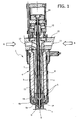
- the number 1 globally designates an injector nozzle which constitutes the fundamental element of the apparatus and of the method for co-injection moulding according to the invention.
- the injector nozzle 1 which shall now be described in detail, is operatively associated to an injection conduit, summarily shown with the reference number 2, of a mould 3.
- the injection equipment may include a plurality of identical injectors 1.
- the injector nozzle 1 comprises a body, globally designated by the reference number 4, which includes an external tubular part 5 with associated heating electrical resistors 6 and an internal tubular part 7 which defines a central axis passage 8.
- the body 4 of the injector nozzle 1 is provided with a nozzle terminal generically designated as G and facing, at its free end, the injection conduit 2.
- the nozzle terminal G is formed by a hollow internal element 9a of a material with high thermal conducibility, and by a hollow external element 9b of a material with lower thermal conducibility.
- the nozzle terminal G is coaxially aligned with the central axial passage 8, through which extend a tubular shutter H and, within it, a pin shutter K.
- a hot chamber body 10 From the side of the body 4 of the injector nozzle 1 that is opposite to the injection conduit 2 is positioned a hot chamber body 10 through which are formed a first channel 11 for the flow of a first fluid plastic material A, and a second flow channel 12 of a second fluid plastic material B.
- the plastic materials A and B are different from each other, and typically the plastic material A is more valuable whilst the plastic material B is less valuable.
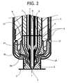
- the first flow channel 11 is separated from the central passage 8 and is formed, for example, according to a substantially helical configuration between the internal element 7 and the external element 5 of the body 4. Said first flow channel 11 joins the central passage 8 at the nozzle terminal G, through an annular chamber 13 formed between the internal element 7 of the body 4 and in part the external element 5 and in part the nozzle terminal G.
- the second flow passage 12 extends axially along the central passage 8, i.e. it consists of the axial annular inter-space between the internal element 7 of the body 4 and the tubular shutter H. Said second flow channel 12 ends upstream of the nozzle terminal G and, as shall be seen, it is connected through it with the injection conduit 2 by means of one or more substantially radial or oblique ports 14 formed in proximity to the end of said tubular shutter H that is oriented towards the nozzle terminal G.
- the tubular shutter H is axially movable along the central passage 8 between a retracted position, in which as shall be seen the communication between the flow channel 11 and the nozzle terminal G is open, and an advanced position in which said communication is closed.
- the movements of the tubular shutter H between the retracted and advanced positions are commanded by means of a first fluid linear actuator 15.
- the pin shutter K can slide within the tubular shutter H and is movable, by means of a second fluid linear actuator 16 coaxial to the first linear actuator 15, between an advanced position in which it shuts off communication between the flow channel 11 and the injection conduit 2, and a retracted position in which said communication is open.
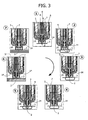
- linear actuators 15 and 16 are operatively connected to an electro-hydraulic control group, not shown in the drawings, whereby they are operated according to a sequential cycle of co-injection of the two plastic materials A, B into the cavity of the mould 3, in the manners described below with reference to Figure 3.
- the co-injection cycle may comprise eight successive steps, number 1 through 7, which follow each other in the direction of the arrow visible in Figure 3, and whereof the first one coincides with the eighth one.
- the pin shutter In the initial step, designated "1", the pin shutter is in the advanced position and the tubular shutter H is in the retracted position. In this way, both the communication between the injection conduit 2 and the first flow channel 11, and the communication between said injection conduit 2 and the second flow channel 12 are shut off. The passage of both materials A and B from the injector nozzle 1 to the cavity of the mould 3 is thus prevented.
- the pin shutter K is moved to a first retracted position, in order to open communication between the flow channel 11 and the injection conduit 2 to inject the fluid plastic material A into the mould 3, whilst the ports 14 remain closed.
- the plastic material A will form the skin of the artefact.
- the pin shutter K is moved to the advanced position, in order to close communication between the flow channel 11 and the injection conduit 2. In this way, the flow of the material A towards the cavity of the mould 3 is stopped.
- the tubular shutter H is placed in the advanced position, in order to shut off communication between the flow channel 11 and the nozzle terminal G.
- a preferential passage is thereby created for the material B which will form the core of the artefact.
- the pin shutter K is brought to a second retracted position in which it opens the ports 14, placing the second flow channel 12 in communication with the nozzle terminal G as well as with the injection conduit 2 to inject the second fluid plastic material B into the cavity of the mould.
- the pin shutter K is moved back to the advanced position, in order to close communication between the second flow channel 12 and the injection conduit 2. In this way, the injection conduit 2 and the point of injection of the second material B are also cleaned.
- the pin shutter K is returned to the first retracted position, in which the ports 14 are closed, and the tubular shutter H is placed in the retracted position, in order to complete the injection of the first material A.
- the material B is totally confined in the core of the artefact, inside the material A.
- the initial condition is restored, so the pin shutter K is placed in the advanced position and the tubular shutter H is in the retracted position, thereby shutting off communication with the injection conduit to both flow channels 11 and 12.
- the injection steps of the first and the second plastic materials could be reversed with respect to the above description: in such a case the co-injection sequential cycle shall provide initially injection of the second material B and subsequently injection of the first material A. It also to be pointed out that the steps disclosed in the above as “3", "4" and “6" could be suppressed. Accordingly, shutting off the flow of the first plastic material A (or of the second plastic material B, respectively) and opening the flow of the second plastic material B (or of the first plastic material A, respectively)into the mould 3 would be carried out in a more abrupt fashion, i.e. without an intermediate step of interruption of the flow of both first and second plastic materials A and B.
- step "7" could be made optional, and in such a case step “1" will immediately follow step “6".
- the actuators 15 and 16 could consist, instead of fluid jacks, of electrical or different actuators. The method according to the invention can be advantageously employed in a variety of applications, among which:
Landscapes
- Engineering & Computer Science (AREA)
- Manufacturing & Machinery (AREA)
- Mechanical Engineering (AREA)
- Injection Moulding Of Plastics Or The Like (AREA)
Priority Applications (1)
| Application Number | Priority Date | Filing Date | Title |
|---|---|---|---|
| EP04011031A EP1595677A1 (fr) | 2004-05-10 | 2004-05-10 | Dispositif et procédé pour le moulage sandwich des résines plastiques |
Applications Claiming Priority (1)
| Application Number | Priority Date | Filing Date | Title |
|---|---|---|---|
| EP04011031A EP1595677A1 (fr) | 2004-05-10 | 2004-05-10 | Dispositif et procédé pour le moulage sandwich des résines plastiques |
Publications (1)
| Publication Number | Publication Date |
|---|---|
| EP1595677A1 true EP1595677A1 (fr) | 2005-11-16 |
Family
ID=34924932
Family Applications (1)
| Application Number | Title | Priority Date | Filing Date |
|---|---|---|---|
| EP04011031A Withdrawn EP1595677A1 (fr) | 2004-05-10 | 2004-05-10 | Dispositif et procédé pour le moulage sandwich des résines plastiques |
Country Status (1)
| Country | Link |
|---|---|
| EP (1) | EP1595677A1 (fr) |
Citations (5)
| Publication number | Priority date | Publication date | Assignee | Title |
|---|---|---|---|---|
| AT391833B (de) * | 1988-10-03 | 1990-12-10 | Engel Gmbh Maschbau | Spritzduese fuer spritzgiessmaschinen |
| JPH06170888A (ja) * | 1992-12-03 | 1994-06-21 | Toyo Mach & Metal Co Ltd | 複合成形機の制御方法 |
| DE29617531U1 (de) * | 1996-10-14 | 1996-12-12 | Battenfeld Gmbh, 58540 Meinerzhagen | Wechseleinsatz für eine Spritzdüse |
| JPH09295327A (ja) * | 1996-04-30 | 1997-11-18 | Nissei Plastics Ind Co | 射出成形機のノズル装置及び射出方法 |
| US6332767B1 (en) * | 1983-04-13 | 2001-12-25 | Pechiney Emballage Flexible Europe | Apparatus for injection molding multi-layer articles |
-
2004
- 2004-05-10 EP EP04011031A patent/EP1595677A1/fr not_active Withdrawn
Patent Citations (5)
| Publication number | Priority date | Publication date | Assignee | Title |
|---|---|---|---|---|
| US6332767B1 (en) * | 1983-04-13 | 2001-12-25 | Pechiney Emballage Flexible Europe | Apparatus for injection molding multi-layer articles |
| AT391833B (de) * | 1988-10-03 | 1990-12-10 | Engel Gmbh Maschbau | Spritzduese fuer spritzgiessmaschinen |
| JPH06170888A (ja) * | 1992-12-03 | 1994-06-21 | Toyo Mach & Metal Co Ltd | 複合成形機の制御方法 |
| JPH09295327A (ja) * | 1996-04-30 | 1997-11-18 | Nissei Plastics Ind Co | 射出成形機のノズル装置及び射出方法 |
| DE29617531U1 (de) * | 1996-10-14 | 1996-12-12 | Battenfeld Gmbh, 58540 Meinerzhagen | Wechseleinsatz für eine Spritzdüse |
Non-Patent Citations (3)
| Title |
|---|
| BRAUN P: "ZWEI KOMPONENTEN ZENTRAL ANGESPRITZT", PLASTVERARBEITER, ZECHNER UND HUETHIG VERLAG GMBH. SPEYER/RHEIN, DE, vol. 49, no. 10, October 1998 (1998-10-01), pages 144,147 - 148,150, XP000933347, ISSN: 0032-1338 * |
| PATENT ABSTRACTS OF JAPAN vol. 018, no. 502 (M - 1676) 20 September 1994 (1994-09-20) * |
| PATENT ABSTRACTS OF JAPAN vol. 1998, no. 03 27 February 1998 (1998-02-27) * |
Similar Documents
| Publication | Publication Date | Title |
|---|---|---|
| JP4283541B2 (ja) | 多層プラスチック品の射出成形 | |
| CN102149527B (zh) | 用于制造具有集成的加强结构的塑料产品的方法和设备 | |
| EP1346808A1 (fr) | Moulage sandwich avec perceé de la matière de coeur et buse à canal chaud pour le moulage par coinjection | |
| CA2687857A1 (fr) | Ebauche et empilement de moule pour produire l'ebauche | |
| US20050248056A1 (en) | Apparatus and method for co-injection moulding of plastic materials | |
| DE2604247A1 (de) | Verfahren zum blasformen sowie hohlkoerperblasmaschine | |
| EP1595677A1 (fr) | Dispositif et procédé pour le moulage sandwich des résines plastiques | |
| WO2016096096A1 (fr) | Procédé de fabrication d'une lentille multicouche en matière plastique | |
| CN106003569A (zh) | 一种双色模内注塑成型工艺及应用该工艺的双色开关插座 | |
| CA2466235A1 (fr) | Dispositif et methode de moulage par co-injection de matieres plastiques | |
| RU2005138313A (ru) | Способ и устройство для изготовления деталей средств передвижения | |
| US10144165B2 (en) | Method and apparatus for the injection molding of plastic materials | |
| US20090152769A1 (en) | Apparatus and method for manufacturing vehicle door trim and vehicle door trim manufactured using the method | |
| KR20180013762A (ko) | 플라스틱 재료 연속 사출 성형 방법 및 장치 | |
| CA2584435A1 (fr) | Systeme de moulage par injection pour le moulage par injection d'une pluralite de matieres | |
| CN104552747A (zh) | 光学组件的制造方法 | |
| CN214605538U (zh) | 一种无流道多喷嘴装置 | |
| JPH05253973A (ja) | 射出成形用金型 | |
| CN101462370B (zh) | 一种dvd塑胶面壳的成型处理方法 | |
| US20030030179A1 (en) | Nozzle for injection molding and injection molding machine | |
| EP1252009B1 (fr) | Procedes et appareil de moulage par injection | |
| CN217495047U (zh) | 一种三明治式分层材料注塑的热流道系统 | |
| US6830447B2 (en) | Valve gate assembly for injection molding | |
| JP6344408B2 (ja) | 樹脂成形品の成形方法 | |
| US7390184B2 (en) | Dual injection manifold |
Legal Events
| Date | Code | Title | Description |
|---|---|---|---|
| PUAI | Public reference made under article 153(3) epc to a published international application that has entered the european phase |
Free format text: ORIGINAL CODE: 0009012 |
|
| AK | Designated contracting states |
Kind code of ref document: A1 Designated state(s): AT BE BG CH CY CZ DE DK EE ES FI FR GB GR HU IE IT LI LU MC NL PL PT RO SE SI SK TR |
|
| AX | Request for extension of the european patent |
Extension state: AL HR LT LV MK |
|
| 17P | Request for examination filed |
Effective date: 20060328 |
|
| AKX | Designation fees paid |
Designated state(s): DE IT |
|
| 17Q | First examination report despatched |
Effective date: 20060504 |
|
| STAA | Information on the status of an ep patent application or granted ep patent |
Free format text: STATUS: THE APPLICATION IS DEEMED TO BE WITHDRAWN |
|
| 18D | Application deemed to be withdrawn |
Effective date: 20081202 |