EP1595188B1 - Thermostatkopf - Google Patents
Thermostatkopf Download PDFInfo
- Publication number
- EP1595188B1 EP1595188B1 EP03710223A EP03710223A EP1595188B1 EP 1595188 B1 EP1595188 B1 EP 1595188B1 EP 03710223 A EP03710223 A EP 03710223A EP 03710223 A EP03710223 A EP 03710223A EP 1595188 B1 EP1595188 B1 EP 1595188B1
- Authority
- EP
- European Patent Office
- Prior art keywords
- thermostatic
- head according
- sleeve
- thermostatic head
- tubular body
- Prior art date
- Legal status (The legal status is an assumption and is not a legal conclusion. Google has not performed a legal analysis and makes no representation as to the accuracy of the status listed.)
- Expired - Lifetime
Links
Images


Classifications
-
- G—PHYSICS
- G05—CONTROLLING; REGULATING
- G05D—SYSTEMS FOR CONTROLLING OR REGULATING NON-ELECTRIC VARIABLES
- G05D23/00—Control of temperature
- G05D23/01—Control of temperature without auxiliary power
- G05D23/02—Control of temperature without auxiliary power with sensing element expanding and contracting in response to changes of temperature
- G05D23/021—Control of temperature without auxiliary power with sensing element expanding and contracting in response to changes of temperature the sensing element being a non-metallic solid, e.g. elastomer, paste
- G05D23/023—Control of temperature without auxiliary power with sensing element expanding and contracting in response to changes of temperature the sensing element being a non-metallic solid, e.g. elastomer, paste the sensing element being placed outside a regulating fluid flow
Definitions
- the present invention relates to a thermostatic head and more in particular to a safety thermostatic head, i.e. equipped with a blocking device preventing its tampering, both unintentional and intentional.
- Thermostatic heads are devices used for controlling other devices according to the value of a thermal signal detected by said head: a typical example of their use is in heating hydraulic systems, where said thermostatic head controls a shutter placed in a pipe portion of the system (for instance in a radiator) for regulating the flow rate of hot water getting through said pipe.
- thermostatic head For convenience's sake the invention shall be described with reference to such kind of thermostatic head, although it will be easy for a skilled technician to transfer said invention to any other kind of thermostatic head starting from said description.
- Thermostatic heads for hydraulic systems are well known: they substantially comprise a tubular body housing a thermostatic motor (or thermostat), which can be equipped with its own heat sensor, or it can be connected to a separate sensor for detecting the temperature of the system, or room temperature, or furthermore it can be connected to a central control system.
- a thermostatic motor or thermostat
- the thermostatic motor moves a stem connected to the shutter, which varies the opening of said shutter, and therefore the water flow in the duct, following the indications given by the sensor or by the central control system.
- Thermostatic heads generally have a turnable control knob for rotating the aforesaid tubular body in a plurality of different operating angular positions with respect to the shutter, so as to establish the maximum water flow rate the thermostat can define.
- Thermostatic heads of this type have some drawbacks: first of all, it may happen that the position set by the knob is changed by a rotation of said knob, either unintentional or intentional, particularly when the thermostatic head is placed in public places and can be touched and moved by people present in said places.
- a first solution consists in providing a covering cage around the thermostatic head, which is of little convenience, anti-aesthetical and not safe enough.
- a second solution consists in introducing into the thermostatic head a blocking pin which blocks or limits the rotation of the knob.
- document GB 1 564 047 shows a thermostatic regulating valve comprising a thermostatic actuator unit and a valve housing.
- the actuator unit comprises a control knob, rotatable relative to a connecting union, that connects the actuator unit to the valve housing, to set a desired temperature value.
- the thermostatic valve comprises also a clamped safety device that blocks the knob against rotation to prevent changes of the desired temperature by unauthorized people.
- thermostat is generally badly coupled with the knob, also due to inaccuracies in the working of the reciprocally facing surfaces of the thermostat and of the knob, at least one of which generally shows a raw finishing degree. That is why the aforesaid surfaces are in contact with each other only in few points.
- the solutions generally known provide for some openings in the knob shell, which should lead outside air in direct contact with thermostat and therefore result in a fast reaction of thermostat whenever outside temperature changes. Said solutions do not ensure a safe result whereas they allow dust to pile up between knob and thermostat.
- thermostatic head by means of a blocking device that is simple, cheap, easy to be operated and that does not modify the usual aesthetic appearance of known thermostatic heads, so that it is difficult to be recognized by unskilled personnel, and that can keep unchanged the reference position of the thermostatic head with respect to the support (pipe) on which it is mounted.
- a thermostatic head according to the invention is particularly compact and small.
- the object of the present invention is therefore a thermostatic head as claimed in the enclosed claims 1 and 17 and in the dependant claims.
- thermostatic head according to the present invention, hereinafter disclosed with reference to the enclosed drawings, provided to a merely indicative and therefore non-limiting purpose, in which:
- thermostatic head according to the invention is hereinafter described with particular reference to the embodiment of a thermostatic head to be used in fluidodynamic systems, in particular heating systems, for controlling the water flow in a pipe, though the invention can also apply to all thermostatic heads, and more generally to all mechanisms rotating around their own axis, which require an anti-tampering device ensuring the block of the rotation that is reliable, cheap and easy to be operated.
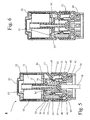
- the thermostatic head 1 substantially comprises, in a per se known way, a tubular body 30 to be coupled with a support sleeve 40, to be coupled in its turn with a ring nut 50 fastened to the system to be controlled, and more particularly to the pipe (not shown) whose flow has to be regulated.
- the coupling between the tubular body 30 and the sleeve 40 is preferably carried out by screwing the tubular body into the sleeve by means of a helical threading 31 obtained on corresponding facing surface portions of the tubular body and of the sleeve.
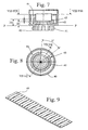
- FIGS. 4-6 show a fast coupling obtained with elastic teeth 41 axially projecting from said sleeve to be introduced into said ring nut 50 and secured by the latter by coupling between corresponding conical surfaces.
- thermostatic motor 11 hereinafter simply referred to as thermostat, is fitted ( Figures 4-6) into the tubular body 30 on the opposite end with respect to the sleeve 40: said thermostat has a central axial channel in which a safety cartridge 12 is mounted.
- the aforesaid cartridge 12 substantially comprises a support tubular element 13 housed in the aforesaid channel and projecting from the latter on the end facing the sleeve.
- the tubular element 13 is integral with a drum 14 housing a cup 15 axially sliding in both senses with respect to the drum, though preferably integral during rotation with said drum.
- the outer side surface of said cup 15 is provided with check teeth 19, which keep together the safety cartridge and prevent the separation of the cup 15 from the drum 14.
- a piston 16 From the base surface of the cup a piston 16, whose free end fits into the channel of the tubular element 13 and slides axially within the latter whenever the reciprocal axial position of drum and cup changes, projects axially towards the channel of the thermostat.
- the telescopic container consisting of the drum-cup assembly contains a coil spring 17 placed around the piston 16, whose ends abut respectively against the inner surface of the drum and the corresponding facing inner surface of the cup. Said spring 17 should prevent the elements of the thermostatic head and of the shutter from being damaged when during summer the thermostatic head is left in a position of maximum closing and the thermostat pushes excessively against the stem 18.
- the outer basic surface of the cup is connected with an end of a stem 18 coaxial with the thermostat; the opposite end of said stem 18 acts onto the shutter (not shown) arranged on the pipe (not shown) whose flow has to be regulated.
- the working of the safety cartridge can be easily inferred: whenever the signal detected by the thermostat changes the support element 13, together with the drum 14, moves axially with respect to the thermostat trailing the cup 15 thanks to the spring, when the shifting is directed towards the shutter, whereas when the shifting is directed away from the shutter, the cup 15 is pushed towards the thermostat by a suitable return spring (not shown in the figures) acting onto the stem 18. Said return spring exerts a smaller thrust than the spring 17 and therefore only pushes the cartridge 12 towards the thermostat when the latter stops acting onto the cartridge 12 for closing the shutter.
- the tubular body 30 is closed by a cap 20, hereinafter referred to as knob, placed as an outside protection for the thermostat ( Figures 1 and 4-6) and used in order to simplify the rotation of the tubular body with respect to the sleeve.
- the knob is made integral with the tubular body in any suitable way, for instance by interference or by gluing, though preferably through a blocking pin 21 introduced with a trip mechanism, for instance through elastic portions, in a corresponding hole ( Figure 4) obtained in the walls of the knob and of the tubular body so as to secure in a safer way the tubular body and the knob.
- an indicator 42 is provided on the outer surface of the sleeve, whereas the outer surface of the adjacent edge of the knob is provided with a scale 22 with reference numbers for the various positions of the tubular body with respect to the sleeve, for instance 0 (tubular body completely in) to 5 (tubular body completely out) with several intermediate positions.
- the position of the blocking pin 21 can coincide with the position of one of said numbers, so that the pin can be a projecting indicator for a specific operating position of the thermostat, for instance, as in the case shown in Figure 2, the standard position referred to with 3, corresponding for instance to a room temperature of 20°C.
- the pin makes it hard to be identified as the blocking element between knob and tubular body.
- the axial position of the thermostat within the knob and, respectively, of the tubular body is preferably secured through spacing means, for instance a washer 23 introduced between the base surface of the knob and the corresponding facing surface of the thermostat.
- the relative rotation of the tubular body with respect to the sleeve shifts axially the safety cartridge associated to the thermostat and the free end of the stem 18 between a position of maximum distance from the shutter (for instance completely open shutter) and a position of minimum distance from the shutter (for instance completely closed shutter), so as to determine the maximum water flow rate the thermostat can define.
- a position of maximum distance from the shutter for instance completely open shutter
- a position of minimum distance from the shutter for instance completely closed shutter
- the thermostatic head comprises interference means 32, 43 for blocking the relative rotation between sleeve and tubular body; these means substantially comprise first blocking means 32 associated inside to said tubular body, and second blocking means 43 associated inside to said sleeve, which can be alternatively associated and dissociated one with respect to the other for activating and de-activating the aforesaid block of the rotation, respectively.
- Said first blocking means 32 comprise at least an element moving between two positions, respectively a passive rest position and an operating position interfering with said second blocking means 43, which can be handled through an opening 34 obtained in the head.
- said moving element is defined by an elongated element 32, for instance prism-shaped, associated to said tubular body and sliding longitudinally with respect to the latter within a suitable seat obtained in said body, axially shifting in both senses, parallel to the axis of said body, between two positions, respectively a rest position (passive) and an interference position (operating) with said second blocking means 43.
- the aforesaid elongated element has an operating end, i.e. the one interfering with the second blocking means 43, and a control end, i.e. the one axially opposed to the operating end.
- said elongated element is carried out by means of a bar 32 with any suitable straight section: in a preferred embodiment the operating end of said bar has a straight section chosen among the circular, triangular, square, rhombic trapezoidal and rectangular section, preferably rectangular section.
- the seat in which the bar 32 slides is obtained in a projection 33 radially protruding from the inner surface of the tubular body and directed towards the axis of said body.
- Said second blocking means 43 preferably comprise ( Figure 7) a ring-shaped projection 43 axially protruding from the inner base surface of said sleeve towards said tubular body.
- the surface of said ring-shaped projection facing the tubular body is shaped as a circular crown 44; the surface of said circular crown 44 is provided on at least a portion of its circular profile with elements interfering with the operating end of the elongated prism-shaped element, in particular with the adjacent end of the bar 32.
- said elements comprise a plurality of teeth 45 axially projecting from the surface of said crown, spaced on their circumference one with respect to the other by a space corresponding to the circumferential profile of the end of said bar 32: in other words, when the bar 32 is brought to its interference position (Fig. 6) its operating end is introduced between a pair of adjacent teeth 45, thus blocking the rotation of the tubular body with respect to said sleeve.
- the surface of the circular crown could be provided with a plurality of axial blind holed, substantially having the same straight section as the end of the bar 32, so that the operating end of said bar in its interference position is introduced into one of said holes, thus blocking any rotation of the tubular body with respect to said sleeve.
- the operating end of said bar has a knurled surface, so as to be engaged against the similarly knurled surface of the circular crown, so that their reciprocal engagement prevents any relative circular shifting between the two elements in contact.
- the elongated element 32 is mounted within the tubular body; in this case the shifting of the bar 32 from its passive to its operating position, and conversely, is preferably driven by the outside of the thermostatic head through the opening 34 obtained within the head, defined by a hole passing through the wall of the knob and through the adjacent wall of the tubular body, in such a position as to make the control end of the bar 32 accessible from outside.
- a suitable tool for instance with a small screwdriver, onto a suitable hooking device obtained on the control end of the bar 32, shifting said bar alternatively between the two aforesaid positions.
- the aforesaid hooking device can comprise a groove 35 obtained along the peripheral profile of the side surface of said elongated prism-shaped element, or a notch or a hole, either a blind or through hole, obtained in the thickness of said element, and more particularly of said bar.
- the surface of the circular crown according to the invention develops on the same inclined plane ( Figures 4-7) as the axis of the sleeve, so as to have in two diametrically opposite points, respectively, a minimum H1 and a maximum H2 distance from any plane P-P perpendicular to the axis of the sleeve.
- said circular crown develops along an helical trajectory comprising only one coil, and still more preferably it has an interruption on the two ends of said coil.
- Said interruption covers an angle w preferably of 15° and 45°, through still more preferably not above 30°.
- the total axial range of the tubular body with respect to the sleeve is carried out with a rotation of said body not above 180°.
- the total axial range of the tubular body with respect to the sleeve can be spread on a rotation of said body of 315 to 360°, preferably of about 330°.
- the surface of the circular crown 44 has minimum H1 and maximum H2 distances from the same plane P-P respectively on the two ends of the helix, i.e. in two adjacent points on the circumference, separated one with respect to the other by an angle preferably corresponding to the angle w.
- any angular rotation of the sleeve during assembly, and of the tubular body thereto connected, with respect to the ring nut 50 does not alter the axial position of the tubular body with respect to said ring nut; in particular, the axial position of the free end of the stem 18 with respect to the shutter of the pipe controlled by the thermostatic head according to the invention is unchanged.
- the sleeve cannot rotate since it is provided with a hexagonal seat fitted into a corresponding hexagonal portion of a connection element (not shown in the figure) in which the stem 18 of the shutter slides and which is fastened to the system on which the thermostatic head is mounted.
- the thermostatic head further comprises heat conduction means for optimizing the contact between the inner surface of the knob and the outer surface of the thermostat.
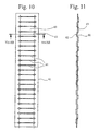
- the aforesaid means comprise ( Figure 9) an elastic metal strip 60, provided with a plurality of cuts 61 ( Figure 10) transversal with respect to the profile of said strip, in which the surfaces 62 and 63 included between three consecutive cuts are alternatively folded in opposite direction ( Figures 11 and 12) perpendicularly to the longitudinal profile of the strip.
- Said strip is shaped as a tube or as a cylinder and is fitted laterally onto the thermostat, between the thermostat and the knob. The surfaces warped in opposite direction ensure a permanent contact along a quite wide surface between the body of the knob and of the thermostat, thus ensuring an optimal heat transmission between the two bodies.
- said means comprise a coil spring 64, preferably not cylindrical, with a variable circular section, fitted onto the thermostat and arranged between the thermostat and the knob, which ensures a continuous contact simultaneously with the knob and with the thermostat.
- the radius of the circular section of said spring varies from D1 corresponding to the outer radius of the thermostat and D2 corresponding to the inner radius of the knob.
- tubular body 30 is screwed onto the sleeve 40, then the bar 32 and the thermostat 11, with the safety cartridge fitted therein, are mounted into the tubular body 30.
- the bar 32 once mounted, prevents the separation of the tubular body 30 from the sleeve, since at a given stroke end it cooperates with an end of the circular crown 44 preventing the reciprocal rotation of tubular body and sleeve until separation.
- the knob 20 is then mounted onto the tubular body 20, remembering to introduce before the spacer 23 with the spring 60 between the knob and the thermostat, the knob is then blocked on the tubular body by means of the pin 21.
- the knob and the tubular body are now integral one with the other during rotation.
- the assembly sleeve-tubular body is now mounted into the sealing ring nut 50 on the system.
- the knob is turned until the tubular body has reached the desired position with respect to the sleeve, as indicated by the position of the scale with respect to the reference 42.
- the bar 32 is now shifted to its operating position, thus blocking any relative rotation between tubular body and sleeve, by interference between the end of the bar 32 and the corresponding pair of teeth 45 on the circular crown 44.
- the invention has important advantages.
- the block of the relative rotation between tubular body and sleeve enables the set values to be kept constant, since any rotation of the knob, both unintentional and intentional, is prevented.
- the access hole to the control end of the bar is very small, so that it will not be noted by those who are not skilled technicians, whereas the control of the bar for de-blocking the knob requires a thin tip introduced into the aforesaid hole, i.e. a tool occasional observers who want to tamper with the thermostatic head out of simple curiosity or in order to alter without permission its operating parameters, are not generally provided with.
- thermostatic head according to the invention is quite small, compact, elegant and reliable and efficiently hides the anti-tampering device it is equipped with. Furthermore, the heat conduction means it is equipped with make said thermostatic head according to the invention extremely sensible to ambient heat changes, minimizing intervention times necessary for updating the system conditions to the new situation, without substantially increasing its cost, weight, overall dimensions and structural complexity with respect to known thermostatic heads at the state of the art.
Landscapes
- Physics & Mathematics (AREA)
- Fluid Mechanics (AREA)
- General Physics & Mathematics (AREA)
- Engineering & Computer Science (AREA)
- Automation & Control Theory (AREA)
- Control Of Temperature (AREA)
- Thermally Actuated Switches (AREA)
- Temperature-Responsive Valves (AREA)
Claims (16)
- Thermostatkopf (1) zur Steuerung eines Strömungssystems, umfassend: einen Thermostatmotor (11), der an einem röhrenförmigen Körper (30) zur Kopplung mit einer zum Körper (30) koaxialen Traghülse (40) befestigt ist, wobei die Hülse (40) wiederum mit dem System gekoppelt werden kann, wobei der röhrenförmige Körper (30) gegenüber der Hülse (40) dreht und in beiden Richtungen dazu zur Bestimmung der vom Thermostat definierbaren maximalen Wasserfördermenge axial beweglich ist; wobei am Kopf (1) Eingriffmittel vorgesehen sind, um den Körper (30) und die Hülse (40) zueinander beim Drehen zu sperren; dadurch gekennzeichnet, daß die Eingriffmittel erste Sperrmittel (32), die innerhalb dem röhrenförmigen Körper (30) verbunden sind, und zweite Sperrmittel (43), die innerhalb der Hülse (40) verbunden sind, umfasst, wobei die ersten (32) und zweiten (43) Sperrmittel mit- oder auseinander selektiv zu verbinden sind, um jeweils die Sperrung beim Drehen zu aktivieren und deaktivieren, und daß die ersten Sperrmittel (32) durch eine im Kopf (1) ausgeformte Öffnung (34) gesteuert werden können.
- Thermostatkopf nach Anspruch 1, dadurch gekennzeichnet, daß die ersten Sperrmittel (32) mindestens ein Element umfassen, das sich zwischen zwei Stellungen bewegt, d.h. einer passiven Ruhestellung und einer Betriebsstellung, die mit den zweiten Sperrmitteln (34) eingreift.
- Thermostatkopf nach Ansprüchen 1 oder 2, dadurch gekennzeichnet, daß das erste Sperrmittel (32) ein längliches Element ist, das mit dem röhrenförmigen Körper (30) verbunden ist und dazu längs läuft, wobei es sich in beiden Richtungen parallel zur Achse des Körpers (30) zwischen den beiden Stellungen verstellt.
- Thermostatkopf nach Anspruch 3, dadurch gekennzeichnet, daß das längliche Element (32) ein Betriebsende zum Eingreifen mit den Sperrmitteln (43) und ein Steuerende in einer Stellung, die zur Stellung des Betriebsendes entgegengesetzt ist, aufweist.
- Thermostatkopf nach Ansprüchen 3 oder 4, dadurch gekennzeichnet, daß das längliche Element (32) einen Stab mit dem Betriebsende, der eine gerade Schnittfläche aus der Gruppe umfassend Kreis-, Vierkant-, Dreieck-, Rauten-, Trapez- und Rechteckschnittflächen aufweist, umfasst.
- Thermostatkopf nach Ansprüchen 4 oder 5, dadurch gekennzeichnet, daß das längliche Element (32) das Steuerende mit einer Kupplungsvorrichtung (35) zur Zwangsaktivierung der in beiden Richtungen abwechselnden Verstellung zwischen der passiven und der Betriebsstellung, und umgekehrt, aufweist.
- Thermostatkopf nach Anspruch 6, dadurch gekennzeichnet, daß die Öffnung (34) ein Durchloch ist, das in der Seitenwand des Kopfes (1) an der Kupplungsvorrichtung (35) des Steuerendes des länglichen Elementes (32) ausgeformt ist, so daß das Steuerende von außen vom Thermostatkopf (1) zugänglich ist.
- Thermostatkopf nach Anspruch 4, dadurch gekennzeichnet, daß die zweiten Sperrmittel (43) einen ringförmigen Vorsprung umfassen, der von der Grundfläche der Hülse (40) zum röhrenförmigen Körper (30) axial hinausragt, wobei der ringförmige Vorsprung die zum röhrenförmigen Körper (30) zugewandte Fläche als Kreiskranz (44) aufweist, die mit Elementen ausgestattet ist, die mit dem Betriebsende des länglichen Elementes (32) eingreifen.
- Thermostatkopf nach Anspruch 8, dadurch gekennzeichnet, daß das Eingriffelement eine Vielzahl von Zähnen (45) umfasst, die von der Fläche des Kranzes axial hinausragen und am Umfang mit einem Abstand zueinander liegen, der dem Umfangsprofil des Betriebsende des länglichen Elementes (32) entspricht.
- Thermostatkopf nach Ansprüchen 8 oder 9, dadurch gekennzeichnet, daß die Fläche am Kreiskranz (44) sich auf einer schiefen Ebene gegenüber der Achse der Hülse (40) entwickelt, um an zwei diametral entgegengesetzten Stellen jeweils einen minimalen H1 und einen maximalen H2 Abstand von irgendeiner Ebene P-P orthogonal zur Achse der Hülse (40) zu haben.
- Thermostatkopf nach Ansprüchen 8, 9 oder 10, dadurch gekennzeichnet, daß die Fläche des Kreiskranzes (44) sich auf einem schraubenförmigen Weg entwickelt.
- Thermostatkopf nach irgendeinem der vorherigen Ansprüche, dadurch gekennzeichnet, daß die ersten Sperrmittel (32) mit den zweiten Sperrmitteln (43) zum Verhindern der Trennung des röhrenförmigen Körpers (30) von der Traghülse (40) weiter zusammenwirken, wodurch ein Endanschlag der gegenseitigen Drehung des Körpers (30) gegenüber der Traghülse (40) definiert wird.
- Thermostatkopf nach irgendeinem der vorherigen Ansprüche, umfassend einen Drehknopf (20), der am röhrenförmigen Körper (30) befestigt ist, und Wärmeleitungsmittel (60), die am Kopf (1) angeordnet sind, zur Optimierung des Wärmeaustausches zwischen dem Drehknopf (20) und dem Thermostatmotor (11), dadurch gekennzeichnet, daß die Wärmeleitungsmittel (60) ein Metallleitelement als Rohr umfassen, das am Thermostatmotor (11) befestigt ist und zwischen dem Thermostat und dem Drehknopf liegt.
- Thermostatkopf nach Anspruch 15, dadurch gekennzeichnet, daß das Metallleitelement (60) einen elastischen Metallstreifen mit einer Vielzahl von Schnitten (61) umfasst, die quer zum Streifenprofil laufen, wobei die zwischen drei hintereinanderliegenden Schnitten (61) definierten Flächen (62, 63) in entgegengesetzten Richtungen orthogonal zum Längsprofil des Streifens abwechselnd gefaltet sind.
- Thermostatkopf nach Anspruch 14, dadurch gekennzeichnet, daß das Metallleitelement (60) eine Schraubenfeder (63) mit einer veränderbaren Kreisschnittfläche umfasst, wobei der Radius der Kreisschnittfläche sich zwischen D1, wesentlich entsprechend dem Außenradius des Thermostats, und D2, wesentlich entsprechend dem Innenradius des Drehknopf (20), abwechselnd ändert.
- Strömungssystem, dadurch gekennzeichnet, daß es einen Thermostatkopf nach irgendeinem der vorherigen Ansprüche umfasst.
Priority Applications (1)
| Application Number | Priority Date | Filing Date | Title |
|---|---|---|---|
| AT03710223T ATE346332T1 (de) | 2003-02-18 | 2003-02-18 | Thermostatkopf |
Applications Claiming Priority (1)
| Application Number | Priority Date | Filing Date | Title |
|---|---|---|---|
| PCT/IT2003/000088 WO2004074956A1 (en) | 2003-02-18 | 2003-02-18 | Thermostatic head |
Publications (2)
| Publication Number | Publication Date |
|---|---|
| EP1595188A1 EP1595188A1 (de) | 2005-11-16 |
| EP1595188B1 true EP1595188B1 (de) | 2006-11-22 |
Family
ID=32894094
Family Applications (1)
| Application Number | Title | Priority Date | Filing Date |
|---|---|---|---|
| EP03710223A Expired - Lifetime EP1595188B1 (de) | 2003-02-18 | 2003-02-18 | Thermostatkopf |
Country Status (5)
| Country | Link |
|---|---|
| EP (1) | EP1595188B1 (de) |
| CN (1) | CN100507791C (de) |
| AU (1) | AU2003214643A1 (de) |
| DE (1) | DE60309935T2 (de) |
| WO (1) | WO2004074956A1 (de) |
Cited By (1)
| Publication number | Priority date | Publication date | Assignee | Title |
|---|---|---|---|---|
| CN104455547A (zh) * | 2014-11-26 | 2015-03-25 | 延安市琥灵节水有限公司 | 恒温调节阀门 |
Families Citing this family (5)
| Publication number | Priority date | Publication date | Assignee | Title |
|---|---|---|---|---|
| DE102009031442B4 (de) * | 2009-07-01 | 2016-03-17 | Danfoss A/S | Betätigungsaufsatz zur Betätigung eines Heizungsventils |
| CN102678968A (zh) * | 2012-05-26 | 2012-09-19 | 张迩骞 | 智能恒温混水阀 |
| ES2529428T3 (es) * | 2012-12-03 | 2015-02-20 | Danfoss A/S | Dispositivo de accionamiento de válvulas termostáticas |
| IT201900002345A1 (it) * | 2019-02-18 | 2020-08-18 | Ivar Spa | Raccordo per il collegamento di tubazioni, in particolare di tubi flessibili |
| IT202200017151A1 (it) | 2022-08-10 | 2024-02-10 | Ivar Spa | Metodo per la regolazione dell’afflusso di fluido ad un elemento riscaldante e relativo dispositivo |
Family Cites Families (6)
| Publication number | Priority date | Publication date | Assignee | Title |
|---|---|---|---|---|
| DE2603461C3 (de) * | 1976-01-30 | 1978-07-27 | Danfoss A/S, Nordborg (Daenemark) | Thermostatisches Regelventil |
| US4176786A (en) * | 1976-11-25 | 1979-12-04 | Braukmann Armaturen Ag | Concealed thermostatic control valve |
| AT382944B (de) * | 1982-05-07 | 1987-04-27 | Herz Armaturen Gmbh | Thermostatventil fuer warmwasser-heizkoerper |
| FR2725771B1 (fr) * | 1994-07-21 | 1997-01-17 | Comap | Tete de robinet thermostatique a gamme de temperatures reglable verrouillable. |
| US6164330A (en) * | 1999-10-12 | 2000-12-26 | Lara-Castro; Manuel | Valve having a flow blocking rotary body |
| CN2526634Y (zh) * | 2001-12-19 | 2002-12-18 | 财团法人金属工业研究发展中心 | 恒温控制阀的电控调整装置 |
-
2003
- 2003-02-18 WO PCT/IT2003/000088 patent/WO2004074956A1/en not_active Ceased
- 2003-02-18 CN CNB038259907A patent/CN100507791C/zh not_active Expired - Fee Related
- 2003-02-18 EP EP03710223A patent/EP1595188B1/de not_active Expired - Lifetime
- 2003-02-18 DE DE60309935T patent/DE60309935T2/de not_active Expired - Lifetime
- 2003-02-18 AU AU2003214643A patent/AU2003214643A1/en not_active Abandoned
Cited By (2)
| Publication number | Priority date | Publication date | Assignee | Title |
|---|---|---|---|---|
| CN104455547A (zh) * | 2014-11-26 | 2015-03-25 | 延安市琥灵节水有限公司 | 恒温调节阀门 |
| CN104455547B (zh) * | 2014-11-26 | 2017-01-18 | 延安市琥灵节水有限公司 | 恒温调节阀门 |
Also Published As
| Publication number | Publication date |
|---|---|
| WO2004074956A1 (en) | 2004-09-02 |
| DE60309935T2 (de) | 2007-09-13 |
| EP1595188A1 (de) | 2005-11-16 |
| CN1742245A (zh) | 2006-03-01 |
| CN100507791C (zh) | 2009-07-01 |
| AU2003214643A1 (en) | 2004-09-09 |
| DE60309935D1 (de) | 2007-01-04 |
Similar Documents
| Publication | Publication Date | Title |
|---|---|---|
| CA2688212C (en) | Valve assembly for regulating the flow rate or differential pressure | |
| US10060104B2 (en) | Multipositional faucet spout | |
| EP1595188B1 (de) | Thermostatkopf | |
| US5899439A (en) | Handle with adjustable stop for flow-control valve | |
| US6019129A (en) | Valve position adjustable lock mechanism | |
| CA2053156C (en) | Thermostatic valve | |
| CA1045099A (en) | Thermostat unit for central heating radiators | |
| FI104511B (fi) | Turvalaite termostaattia varten | |
| US20090093209A1 (en) | Damper for an air duct | |
| US5983939A (en) | Single-control mixing valve | |
| US5230465A (en) | Control knob for a thermostatically regulated valve | |
| US5317954A (en) | Pressure switch assembly | |
| EP3054365B1 (de) | Thermostat | |
| US4290553A (en) | Rotary knob for thermostatic valves of radiators | |
| RU2320913C2 (ru) | Устройство для выбора рабочего режима головок управления, в частности, для термостатических клапанов | |
| US2810525A (en) | Control device for fluid fuel burners | |
| DK155550B (da) | Reguleringsventil, isaer en termostatisk styret ventil | |
| EP0903525B1 (de) | Steuerungsvorrichtung für ein Thermostatventil | |
| EP1154176B1 (de) | Einbauventil | |
| US5251811A (en) | Temperature-setting system for thermostatic mixing valve | |
| US4016804A (en) | Thermostatic control unit for radiator valves | |
| CN210153279U (zh) | 一种同轴双控恒温阀芯 | |
| EP1701235B1 (de) | Thermostatisches Ventiloberteil | |
| US5242108A (en) | Control knob for thermostatically regulated mixing valve | |
| EP3193049B1 (de) | Ventil |
Legal Events
| Date | Code | Title | Description |
|---|---|---|---|
| PUAI | Public reference made under article 153(3) epc to a published international application that has entered the european phase |
Free format text: ORIGINAL CODE: 0009012 |
|
| 17P | Request for examination filed |
Effective date: 20050726 |
|
| AK | Designated contracting states |
Kind code of ref document: A1 Designated state(s): AT BE BG CH CY CZ DE DK EE ES FI FR GB GR HU IE IT LI LU MC NL PT SE SI SK TR |
|
| AX | Request for extension of the european patent |
Extension state: AL LT LV MK RO |
|
| RAX | Requested extension states of the european patent have changed |
Extension state: LV Payment date: 20050726 Extension state: AL Payment date: 20050726 |
|
| GRAP | Despatch of communication of intention to grant a patent |
Free format text: ORIGINAL CODE: EPIDOSNIGR1 |
|
| GRAS | Grant fee paid |
Free format text: ORIGINAL CODE: EPIDOSNIGR3 |
|
| GRAA | (expected) grant |
Free format text: ORIGINAL CODE: 0009210 |
|
| AK | Designated contracting states |
Kind code of ref document: B1 Designated state(s): AT BE BG CH CY CZ DE DK EE ES FI FR GB GR HU IE IT LI LU MC NL PT SE SI SK TR |
|
| AX | Request for extension of the european patent |
Extension state: AL LV |
|
| PG25 | Lapsed in a contracting state [announced via postgrant information from national office to epo] |
Ref country code: SI Free format text: LAPSE BECAUSE OF FAILURE TO SUBMIT A TRANSLATION OF THE DESCRIPTION OR TO PAY THE FEE WITHIN THE PRESCRIBED TIME-LIMIT Effective date: 20061122 Ref country code: NL Free format text: LAPSE BECAUSE OF FAILURE TO SUBMIT A TRANSLATION OF THE DESCRIPTION OR TO PAY THE FEE WITHIN THE PRESCRIBED TIME-LIMIT Effective date: 20061122 Ref country code: CH Free format text: LAPSE BECAUSE OF FAILURE TO SUBMIT A TRANSLATION OF THE DESCRIPTION OR TO PAY THE FEE WITHIN THE PRESCRIBED TIME-LIMIT Effective date: 20061122 Ref country code: LI Free format text: LAPSE BECAUSE OF FAILURE TO SUBMIT A TRANSLATION OF THE DESCRIPTION OR TO PAY THE FEE WITHIN THE PRESCRIBED TIME-LIMIT Effective date: 20061122 Ref country code: FI Free format text: LAPSE BECAUSE OF FAILURE TO SUBMIT A TRANSLATION OF THE DESCRIPTION OR TO PAY THE FEE WITHIN THE PRESCRIBED TIME-LIMIT Effective date: 20061122 Ref country code: AT Free format text: LAPSE BECAUSE OF FAILURE TO SUBMIT A TRANSLATION OF THE DESCRIPTION OR TO PAY THE FEE WITHIN THE PRESCRIBED TIME-LIMIT Effective date: 20061122 |
|
| REG | Reference to a national code |
Ref country code: GB Ref legal event code: FG4D |
|
| REG | Reference to a national code |
Ref country code: CH Ref legal event code: EP |
|
| REG | Reference to a national code |
Ref country code: IE Ref legal event code: FG4D |
|
| REF | Corresponds to: |
Ref document number: 60309935 Country of ref document: DE Date of ref document: 20070104 Kind code of ref document: P |
|
| PG25 | Lapsed in a contracting state [announced via postgrant information from national office to epo] |
Ref country code: BG Free format text: LAPSE BECAUSE OF FAILURE TO SUBMIT A TRANSLATION OF THE DESCRIPTION OR TO PAY THE FEE WITHIN THE PRESCRIBED TIME-LIMIT Effective date: 20070222 Ref country code: SE Free format text: LAPSE BECAUSE OF FAILURE TO SUBMIT A TRANSLATION OF THE DESCRIPTION OR TO PAY THE FEE WITHIN THE PRESCRIBED TIME-LIMIT Effective date: 20070222 Ref country code: DK Free format text: LAPSE BECAUSE OF FAILURE TO SUBMIT A TRANSLATION OF THE DESCRIPTION OR TO PAY THE FEE WITHIN THE PRESCRIBED TIME-LIMIT Effective date: 20070222 |
|
| PG25 | Lapsed in a contracting state [announced via postgrant information from national office to epo] |
Ref country code: MC Free format text: LAPSE BECAUSE OF NON-PAYMENT OF DUE FEES Effective date: 20070228 |
|
| PG25 | Lapsed in a contracting state [announced via postgrant information from national office to epo] |
Ref country code: ES Free format text: LAPSE BECAUSE OF FAILURE TO SUBMIT A TRANSLATION OF THE DESCRIPTION OR TO PAY THE FEE WITHIN THE PRESCRIBED TIME-LIMIT Effective date: 20070305 |
|
| REG | Reference to a national code |
Ref country code: GR Ref legal event code: EP Ref document number: 20070400578 Country of ref document: GR |
|
| PG25 | Lapsed in a contracting state [announced via postgrant information from national office to epo] |
Ref country code: PT Free format text: LAPSE BECAUSE OF FAILURE TO SUBMIT A TRANSLATION OF THE DESCRIPTION OR TO PAY THE FEE WITHIN THE PRESCRIBED TIME-LIMIT Effective date: 20070423 |
|
| NLV1 | Nl: lapsed or annulled due to failure to fulfill the requirements of art. 29p and 29m of the patents act | ||
| ET | Fr: translation filed | ||
| REG | Reference to a national code |
Ref country code: CH Ref legal event code: PL |
|
| PLBE | No opposition filed within time limit |
Free format text: ORIGINAL CODE: 0009261 |
|
| STAA | Information on the status of an ep patent application or granted ep patent |
Free format text: STATUS: NO OPPOSITION FILED WITHIN TIME LIMIT |
|
| 26N | No opposition filed |
Effective date: 20070823 |
|
| PG25 | Lapsed in a contracting state [announced via postgrant information from national office to epo] |
Ref country code: IE Free format text: LAPSE BECAUSE OF NON-PAYMENT OF DUE FEES Effective date: 20070219 |
|
| PG25 | Lapsed in a contracting state [announced via postgrant information from national office to epo] |
Ref country code: EE Free format text: LAPSE BECAUSE OF FAILURE TO SUBMIT A TRANSLATION OF THE DESCRIPTION OR TO PAY THE FEE WITHIN THE PRESCRIBED TIME-LIMIT Effective date: 20061122 |
|
| PG25 | Lapsed in a contracting state [announced via postgrant information from national office to epo] |
Ref country code: CY Free format text: LAPSE BECAUSE OF FAILURE TO SUBMIT A TRANSLATION OF THE DESCRIPTION OR TO PAY THE FEE WITHIN THE PRESCRIBED TIME-LIMIT Effective date: 20061122 Ref country code: LU Free format text: LAPSE BECAUSE OF NON-PAYMENT OF DUE FEES Effective date: 20070218 |
|
| PG25 | Lapsed in a contracting state [announced via postgrant information from national office to epo] |
Ref country code: HU Free format text: LAPSE BECAUSE OF FAILURE TO SUBMIT A TRANSLATION OF THE DESCRIPTION OR TO PAY THE FEE WITHIN THE PRESCRIBED TIME-LIMIT Effective date: 20070523 |
|
| REG | Reference to a national code |
Ref country code: FR Ref legal event code: PLFP Year of fee payment: 14 |
|
| REG | Reference to a national code |
Ref country code: FR Ref legal event code: PLFP Year of fee payment: 15 |
|
| REG | Reference to a national code |
Ref country code: FR Ref legal event code: PLFP Year of fee payment: 16 |
|
| PGFP | Annual fee paid to national office [announced via postgrant information from national office to epo] |
Ref country code: DE Payment date: 20200228 Year of fee payment: 18 Ref country code: GR Payment date: 20200226 Year of fee payment: 18 Ref country code: GB Payment date: 20200226 Year of fee payment: 18 |
|
| PGFP | Annual fee paid to national office [announced via postgrant information from national office to epo] |
Ref country code: SK Payment date: 20200129 Year of fee payment: 18 Ref country code: CZ Payment date: 20200213 Year of fee payment: 18 |
|
| PGFP | Annual fee paid to national office [announced via postgrant information from national office to epo] |
Ref country code: TR Payment date: 20200210 Year of fee payment: 18 |
|
| REG | Reference to a national code |
Ref country code: DE Ref legal event code: R119 Ref document number: 60309935 Country of ref document: DE |
|
| GBPC | Gb: european patent ceased through non-payment of renewal fee |
Effective date: 20210218 |
|
| REG | Reference to a national code |
Ref country code: SK Ref legal event code: MM4A Ref document number: E 1537 Country of ref document: SK Effective date: 20210218 |
|
| PG25 | Lapsed in a contracting state [announced via postgrant information from national office to epo] |
Ref country code: CZ Free format text: LAPSE BECAUSE OF NON-PAYMENT OF DUE FEES Effective date: 20210218 |
|
| PG25 | Lapsed in a contracting state [announced via postgrant information from national office to epo] |
Ref country code: GR Free format text: LAPSE BECAUSE OF NON-PAYMENT OF DUE FEES Effective date: 20210906 Ref country code: SK Free format text: LAPSE BECAUSE OF NON-PAYMENT OF DUE FEES Effective date: 20210218 |
|
| PG25 | Lapsed in a contracting state [announced via postgrant information from national office to epo] |
Ref country code: GB Free format text: LAPSE BECAUSE OF NON-PAYMENT OF DUE FEES Effective date: 20210218 Ref country code: DE Free format text: LAPSE BECAUSE OF NON-PAYMENT OF DUE FEES Effective date: 20210901 |
|
| PGFP | Annual fee paid to national office [announced via postgrant information from national office to epo] |
Ref country code: IT Payment date: 20220215 Year of fee payment: 20 Ref country code: FR Payment date: 20220224 Year of fee payment: 20 Ref country code: BE Payment date: 20220224 Year of fee payment: 20 |
|
| REG | Reference to a national code |
Ref country code: BE Ref legal event code: MK Effective date: 20230218 |
|
| PG25 | Lapsed in a contracting state [announced via postgrant information from national office to epo] |
Ref country code: TR Free format text: LAPSE BECAUSE OF NON-PAYMENT OF DUE FEES Effective date: 20210218 |