EP1594382B1 - Vorrichtung zu einem öffnungsfähigen fahrzeugdach und entsprechendes fahrzeug - Google Patents
Vorrichtung zu einem öffnungsfähigen fahrzeugdach und entsprechendes fahrzeug Download PDFInfo
- Publication number
- EP1594382B1 EP1594382B1 EP04712074A EP04712074A EP1594382B1 EP 1594382 B1 EP1594382 B1 EP 1594382B1 EP 04712074 A EP04712074 A EP 04712074A EP 04712074 A EP04712074 A EP 04712074A EP 1594382 B1 EP1594382 B1 EP 1594382B1
- Authority
- EP
- European Patent Office
- Prior art keywords
- roof
- movement
- vehicle
- parcel shelf
- shelf
- Prior art date
- Legal status (The legal status is an assumption and is not a legal conclusion. Google has not performed a legal analysis and makes no representation as to the accuracy of the status listed.)
- Expired - Lifetime
Links
- 230000007246 mechanism Effects 0.000 claims description 25
- 244000261422 Lysimachia clethroides Species 0.000 description 5
- 230000009471 action Effects 0.000 description 3
- 230000000295 complement effect Effects 0.000 description 2
- 239000006185 dispersion Substances 0.000 description 2
- 238000006073 displacement reaction Methods 0.000 description 2
- BASFCYQUMIYNBI-UHFFFAOYSA-N platinum Chemical compound [Pt] BASFCYQUMIYNBI-UHFFFAOYSA-N 0.000 description 2
- 230000009467 reduction Effects 0.000 description 2
- 230000000284 resting effect Effects 0.000 description 2
- 238000007789 sealing Methods 0.000 description 2
- 230000003100 immobilizing effect Effects 0.000 description 1
- 230000006872 improvement Effects 0.000 description 1
- 230000003993 interaction Effects 0.000 description 1
- 239000000463 material Substances 0.000 description 1
- 229910052697 platinum Inorganic materials 0.000 description 1
- 239000007787 solid Substances 0.000 description 1
- 230000001360 synchronised effect Effects 0.000 description 1
Images


Classifications
-
- B—PERFORMING OPERATIONS; TRANSPORTING
- B60—VEHICLES IN GENERAL
- B60J—WINDOWS, WINDSCREENS, NON-FIXED ROOFS, DOORS, OR SIMILAR DEVICES FOR VEHICLES; REMOVABLE EXTERNAL PROTECTIVE COVERINGS SPECIALLY ADAPTED FOR VEHICLES
- B60J7/00—Non-fixed roofs; Roofs with movable panels, e.g. rotary sunroofs
- B60J7/20—Vehicle storage compartments for roof parts or for collapsible flexible tops
- B60J7/205—Vehicle storage compartments for roof parts or for collapsible flexible tops where the boot lid opens in rearward direction to receive the roof and in forward direction to receive luggage
-
- B—PERFORMING OPERATIONS; TRANSPORTING
- B60—VEHICLES IN GENERAL
- B60J—WINDOWS, WINDSCREENS, NON-FIXED ROOFS, DOORS, OR SIMILAR DEVICES FOR VEHICLES; REMOVABLE EXTERNAL PROTECTIVE COVERINGS SPECIALLY ADAPTED FOR VEHICLES
- B60J7/00—Non-fixed roofs; Roofs with movable panels, e.g. rotary sunroofs
- B60J7/20—Vehicle storage compartments for roof parts or for collapsible flexible tops
- B60J7/202—Vehicle storage compartments for roof parts or for collapsible flexible tops being characterised by moveable cover parts for closing the gap between boot lid and rearmost seats
- B60J7/203—Vehicle storage compartments for roof parts or for collapsible flexible tops being characterised by moveable cover parts for closing the gap between boot lid and rearmost seats the cover part comprising cover side flaps
Definitions
- the present invention relates to retractable roof devices and vehicles equipped with such devices. It relates more particularly to a retractable roof device according to the preamble of claim 1.
- a device of this type is known from the document US 5,967,593 .
- the invention also relates to a vehicle equipped with such a device.
- a vehicle comprises a retractable roof device. To clarify the description that follows, we will define the two extreme positions of the roof.
- the roof panel 6 When the roof panel 6 is resting on the frame of the vehicle, and in particular on the upper amount of the windshield, that is to say when the roof performs a cover function of the passenger compartment formed by the driving position and all the passenger seats, the roof is said in the closed position.
- the roof is said in retracted position.
- a rear cover structure 10 is located behind the roll bars.
- it comprises a substantially horizontal rear shelf 12.
- the rear shelf 12 is located in the same way behind the roll bars, substantially horizontal.
- shutters 14 are necessary from an aesthetic point of view so that the vehicle in the open position has a solid surface, from an aerodynamic point of view to avoid disturbances in the flow of air, and also a point of view of the tightness of the mechanism present under the shelf 12.
- the rear shelf 12 changes position and passes successively from an initial position, said rest position and preferably substantially horizontal, to a so-called open position and preferably substantially vertical to provide room for the passage of the roof, before finally returning to a substantially horizontal position.
- the rear shelf 12 when the roof is in the closed position or in the retracted position, the rear shelf 12 has an angle with the horizontal plane, so that the rear part of the shelf 12 is lower than the front part of the shelf 12.
- the movement of the rear shelf 12 during a retraction of the roof can proceed as follows: In the closed position, the shelf 12, substantially horizontal, is pinched in its rear part by the rear part of the roof.
- a control unit controls a first movement of the trunk door to release the storage space dedicated to the roof in the rear portion 8 of the vehicle. While the trunk door continues to pivot to the rear 8 of the vehicle, along a transverse axis of the vehicle, the roof is moved by a hydraulic action of a control cylinder.
- a cam system 24 the rotational movement of the roof generates a rotation of the tablet 12.
- the rear shelf 12 performs a first downward movement of the vehicle along a transverse axis of the vehicle.
- the tablet 12 performs a second rotational movement, this time towards the top of the vehicle, according to the same transverse axis. This second rotation movement takes place until the tablet 12 is abutted in a substantially vertical position. While the shelf 12 is in this stop position, the roof continues its retraction in the storage space dedicated to it and now causes the rotation of the shutters 14 closing.
- the folding of the shelf 12 is then controlled by the folding of the trunk door.
- a mechanical cable for example of the type of bicycle brake cables known as the Bowden cable, transmits a force generated by the closing mechanism of the trunk door to a device connected to the shelf 12.
- the control unit that is to say while the roof is not yet completely retracted
- a simultaneous movement of the rear shelf 12 is generated by the cable connection, so as to bring back the shelf 12 back, now grafted two shutters 14 closing, in a substantially horizontal position.
- the movement of the rear shelf 12 to allow the passage of the roof from a retracted position to a closed position is symmetrically the same.
- the tablet 12 is initially brought into abutment in a substantially vertical position, then brought back to a substantially horizontal position. These movements are created by the rotation of the roof finding a closed position and by the action of the Bowden cable transmitting to the shelf 12 the movements of the trunk door.
- closure flaps 14 are on either side of the rear shelf 12 for aesthetic, aerodynamic and sealing purposes.
- these same shutters 14 can not be closed in this position, because they would interfere with the passage of the arms associated with the roof. In the closed position, these flaps 14 are slid under the rear shelf 12. The principle of the movement of flaps 14 is as follows:
- the flaps 14 remain slid under the shelf 12 when the roof is in the closed position, and when the roof begins to be driven in a rotational movement. They remain slid in this position until the shelf 12 is in abutment in substantially vertical position. In this position, the rotation of the roof along a transverse axis of the vehicle causes the cams 24 to move the flaps 14.
- the movement of the flaps 14 In order to move from a position slid under the shelf 12 to a position next to the shelf 12 by forming a plane with this shelf 12, the movement of the flaps 14 must be both a release movement under the shelf 12 and a translational movement to reach the same height as the shelf 12.
- these two movements are performed simultaneously by a rotation helical. It will be understood that these two movements can be made successively by a rotational movement and then translation, or by two translational movements.
- a continuous rotational movement of the roof causes two successive movements, the movement of the shelf 12 at first and then the movement of the shutters 14 closing. Symmetrically along the median axis of the vehicle, the mechanism described later for a left side of the vehicle is the same for the right side.
- the continuous rotational movement of the roof is generated by a hydraulic control.
- a cylinder consisting of a body and a piston, is articulated on the body, at the end of the body of the cylinder by which the piston opens. Such articulation allows a movement of the cylinder body without being too penalizing for the longitudinal thrust of the piston.
- This movement of the piston generates the movement of two connecting rods respectively connected to the free end of the piston.
- a first link is secured to the body, providing both a guide of the movement of the piston and a holding thereof when it is in extension, and a second connecting rod, called reduction rod, mounted in free rotation on the arm Inside the roof, the arm supporting the roof located towards the passenger compartment, makes it possible to transfer the translation movement of the piston in a rotary movement of this inner arm.
- the reduction rod pulls the inner arm towards the cylinder when the piston retracts and conversely pushes the inner arm when the piston expands out of the cylinder body.
- the lower part of the inner arm being mounted to rotate about a fixed axis, said main axis of rotation 22, the movement of the inner arm is a rotational movement about this axis.
- the mobility of the roof, supported by the articulated quadrilateral is therefore generated by the substantially longitudinal movement of the piston and effected via a rotation of the main axis 22.
- This main axis of rotation 22 also carries at least a first pulley 20 having a projection perpendicular to the axis of rotation and a groove around the periphery of the first pulley 20.
- the main axis of rotation 22 also carries at least one cam ( of the system 24) having a radial protuberance.
- the arm interior extends from its end towards the interior of the vehicle, this extension being parallel to the main axis of rotation 22.
- the relative position of the various elements carried by the main axis of rotation 22 is such that the inner arm is located towards the outside of the vehicle, the cam 24 is located towards the inside of the vehicle and the first pulley 20 is located between the arm and the cam 24.
- the extension of the inner arm parallel to the main axis of rotation 22 therefore cuts the plane of rotation of the first pulley 20 and the radial projection of the first pulley 20 has a dimension such that it can be in contact with the extension of the inner arm parallel to the main axis of rotation 22.
- a substantially “L” lever is articulated at one of its ends on the cam 24 and has an orifice allowing the passage of the radial protuberance of the cam 24 in an extreme position.
- the other end of the lever is rotatably mounted about an axis integral with the tablet 12.
- a second pulley is rotatably mounted about a second axis of rotation carried by a casing, which also carries the main axis of rotation 22.
- This second pulley has a groove in which a mechanical cable, of the type brake cable bicycle , is inserted. This cable is connected to the opening mechanism of the trunk door.
- the cam 24 is connected to one end of a return spring whose other end is secured to the housing. This return spring tends to bring the tablet 12, via the cam 24 and the "L-shaped lever", back to a substantially horizontal position, when the second pulley, which blocks the radial protuberance of the cam 24, is actuated by the cable. the safe door. The cam 24 is then released and returns to contact with the extension of the inner arm by the return function of the spring.
- the extension of the inner arm has a first and a second surface adapted to cooperate simultaneously with a third surface of the projection of the first pulley 20 and with a fourth surface of the cam 24. These third and fourth surfaces are arranged so that, in a rest position when the shelf 12 is lowered and the roof closed, not be in a plane parallel to the plane defined by the first and second surfaces of the extension of the inner arm.
- the cam 24 is thus shifted in the rest position relative to the first pulley 20 so that during the retraction of the roof, and thus the rotation of the inner arm, the second surface of the extension of the inner arm comes all firstly in contact with the fourth surface of the cam 24 and first generates the rotation of the cam 24 around the main axis of rotation 22.
- the rotation of this cam 24 causes on the one hand the displacement of the "lever L "and therefore the shelf 12 in a vertical position, and secondly the displacement of the radial protuberance of the cam 24 which then engages in a groove of the second pulley.
- the movement of the cylinder relative to the axis is a helical rotation movement which allows the release of the flap 14 from under the shelf 12 and at the same time makes it possible to restore the flap 14 to a substantially equivalent vertical level.
- the helical rotation movement of the closure flaps 14 is therefore initiated by the rotation of the first pulley 20 carried by the main axis of rotation 22.
- the operation proceeds symmetrically in the same way.
- the opening of the trunk door and the setting in motion of the hinged assembly supporting the roof engender the positioning of the rear shelf 12 in a substantially vertical position and causes the release of the stops made by the first and second surfaces of the extension of the inner arm on the third surface of the first pulley 20 and the fourth surface of the cam 24.
- a spring system placed between the axis and the cylinder used for the helical rotation of the closure flaps 14 then allows, when the pressure exerted by the cable on the cylinder no longer exists, that is to say when the first pulley 20 has disengaged following the rotation of the main axis 22, to return the flaps 14 in position under the shelf 12 to allow the passage of arms supporting the roof structure.
- the closed position of the roof, in which the articulated assembly supporting the roof has a lower part under the body structure and an upper part connected to the roof and therefore above this body structure, and the position retracted from this roof, in which the articulated assembly is entirely located under the body structure, involves the creation of an orifice in the body structure to allow the passage of the articulated assembly.
- These openings can not be discovered when the roof is in the retracted position for reasons of aesthetics, aerodynamics or sealing.
- the inner arm supporting the roof has a bent shape near its lower end. This bent shape is complementary to a cam 24, specific to a hatch, not shown and located in the vehicle structure, in an area substantially close to the shelf 12.
- the present invention also relates to a mechanism of the safe door.
- a vehicle whose rigid roof can be retracted in a dedicated storage space at the rear of the vehicle must have a trunk door to the particular kinematics.
- the trunk door must allow a standard opening, to store luggage in the trunk.
- the trunk door is rotatably mounted about a transverse axis in the part of the trunk door located furthest forward of the vehicle, when the trunk door is in the closed position: access to the trunk is done then, when the trunk door is open, by the rear 8 of the vehicle.
- the roof is stored in a storage space that is dedicated to him in the trunk area.
- the trunk door must open to allow passage to the roof and a standard opening does not allow it.
- the trunk door must then pivot about a second axis of transverse rotation, in the part of the trunk door located furthest back of the vehicle, when the trunk door is in the closed position: access to the trunk is done then, when the trunk door is open, by the front of the vehicle and allows the passage of the roof and its associated mechanism.
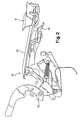
- the trunk door is set in motion by a set of three main elements, namely a lock device comprising a hinge called “gooseneck" and two side mechanisms symmetrically arranged on each side of the trunk door. Only the lateral mechanism on the left side of the vehicle will be described, the corresponding lateral mechanism on the right side being found by symmetry.
- This lateral mechanism is composed of a plate secured to the body, an intermediate frame hinged to this plate, a first pneumatic system, one end of which is fixed to the plate and whose other end is connected to the intermediate frame, and a hinge system located between the intermediate frame and the boot door and formed of connecting rods and a second pneumatic system.
- the plate makes it possible to group, on the same part, various functionalities such as an articulation of the intermediate frame, immobilization means offering the possibility of locking this frame in the ready-to-assemble position, the fixing of the first pneumatic system controlling the movement of the intermediate frame .
- This plate is made of a light material, is thin and can advantageously have a triangular shape.
- the intermediate frame is constituted of a single piece, substantially shaped "double L".
- a first portion, said hinge portion, is mounted on the plate by a pivot connection along an axis substantially transverse to the vehicle and perpendicular to the plane of the plate.
- This first articulation part also carries the free end of the first pneumatic system, the translational movement of the piston generating, by this freely rotating connection and the point of articulation of the chassis on the plate, a rotational movement of the frame intermediate around an axis transverse to the vehicle and perpendicular to the plane of the plate.
- the intermediate frame has a first bent portion which connects the first hinge portion to a second portion, said transfer. This second transfer part and the first articulation part has a substantially straight angle.
- a second bent portion is extended by a third portion, said support, substantially parallel to the first hinge portion.
- This third support portion has different pivot points on which are fixed the different connecting rods of the articulation system, located between the third support portion of the intermediate frame and a support plate secured to the trunk door.
- the free end of the piston of the second pneumatic system is also fixed on the third support portion of the frame, the cylinder body of the second pneumatic system being connected to the support plate secured to the trunk door.
- the piston of the second pneumatic system compressed when the trunk door is closed, relaxes as soon as the lock of the trunk door is unlocked.
- the span of this piston then generates an opening of the trunk door, accompanied by the links of the articulation system connected to the third support portion of the intermediate frame.
- the intermediate frame does not move and remains fixed relative to the plate by the action of immobilization means mounted on this plate.
- a pin mounted on the frame for example at the level of the second curved portion, may have for this purpose a shape complementary to a system of hooks of the immobilizing means.
- the arrangement of the assembly formed by the plate and the frame is such that advantageously the first hinge portion and the third support portion of the intermediate frame are substantially oriented horizontally and the second part transfer is substantially vertically oriented.
- a pulley can be fixed to the intermediate frame and serve as a guide by its complementarity with a groove on the plate.
- this pulley / groove assembly is made at the ends of the plate and the frame remote from their common point of articulation.
- Safe hooking of the frame relative to the plate is necessary so that the opening of the trunk door for the storage of luggage is via a joint resting on a substantially horizontal and rigid structure. It is also interesting for the manufacturer during assembly of the vehicle, because the assembly formed by the plate and the hooked frame in the lock can thus be provided ready to mount without having dispersion between each mounting on the vehicle. The repetitiveness presented by such a system then offers a time saving and an assembly quality of interest for the manufacturers.
- the intermediate frame When opening the trunk by rotating the trunk door about the second transverse axis of rotation in the part of the trunk door located furthest back of the vehicle, that is to say at the opening of the the trunk door to allow the retraction of the roof, the intermediate frame is detached from the lock of the plate.
- the first pneumatic system is fixed on the plate, advantageously in the lower part of this plate, the free end of the piston being, as described above, connected to the intermediate frame.
- the piston of first pneumatic system compressed when the intermediate frame is in a rest position, relaxes as soon as the lock of the plate no longer holds the pin of the intermediate frame.
- the span of this piston then its control by hydraulic pressure, then generates a rotation of the intermediate frame along an axis of rotation perpendicular to the plate and therefore substantially parallel to the second axis of transverse rotation.
- the control of the second pneumatic system located between the third support portion of the frame and the support plate integral with the trunk door, is such that the second pneumatic system remains compressed.
- the rods of the hinge system located between the third support portion of the intermediate frame and the support plate secured to the trunk door remain in this case at rest and do not articulate.
- the system transmits the rotational movement of the intermediate frame to the trunk door, which rotates about a transverse axis specific to the trunk door and different from the intermediate frame.
- This rotational movement is performed around a transverse axis which advantageously passes through the lock of the trunk door.
- This lock thus has a particular structure to take into account the opening of the trunk according to the second transverse axis of rotation passing through the lock and not to generate effort in the lock, which would be the case with a conventional lock and a safe door that moves while hanging.
- This lock is based on a structure advantageously formed of two parts, a fixed frame integral with the body structure of the vehicle and a hinge called “gooseneck" which moves in a slide of the frame.
- the curved shape of the slide and the shape of the corresponding hinge generates a movement of this hinge equivalent to a rotational movement about a transverse axis comparable to the second axis of transverse rotation around which the trunk door is rotating.
- the upper part of the "gooseneck” hinge carries the strike and the bolt of the lock that will correspond to an area fitted out in the lower part of the trunk door. Thanks to the curved connection between the frame and the hinge, the two elements of the lock carried by both the body and the trunk door can tilt in a coordinated manner.
- the movement of the "gooseneck” hinge corresponds to the movement of the trunk door in lower proportions. This combination of movements allows a rotational movement of the trunk door without generating stress on the lock in contact with the trunk door.
- the opening of the trunk door for the retraction of the roof therefore rests, inter alia, on two lateral systems and a lock system, comprising a hinge "gooseneck", independent.
- the intermediate frame is formed of a single piece, which provides a room saving, and therefore weight and money, and a better stability of each side system.
- the synchronization of the movements of the two lateral systems is achieved by sending equivalent command pressure in the first pneumatic systems. Such a synchronization thus makes it possible to dispense with a mechanical appendix connecting the two lateral systems.
- the trunk door can have a predetermined flexibility to adapt to the movements of the independent lateral systems.
- the mounting of the mechanisms of the roof and the trunk door on the vehicle can be achieved in the following manner.
- the underbody of a vehicle namely all of the body structures of the vehicle, excluding openings and roof, arrives on a assembly line.
- a first assembly formed inter alia by the plate and the intermediate frame, clipped on the plate, is mounted on the side flanks inside the trunk area.
- This assembly also comprises the second pneumatic system and the articulation system formed of connecting rods, and the support plate intended to be secured to the trunk door.
- the assembly is delivered to the assembly line with the plate and chassis clipped, with the system folded hinge and the second pneumatic system connected at its cylinder body to the support plate and clipped at the end of its piston also on the support plate.
- This end of the piston is intended, at the end of the assembly, to be fixed on the third support portion of the intermediate frame. It is first clipped on the support plate for easy handling by the operator, and is then unclipped and placed in position on the frame as soon as the side openings are installed. It should be noted that the fact that the platinum / chassis assembly arrives on the clipped assembly line makes it possible to fix the assembly without dispersion between each assembly. The support plate is then secured to the trunk door when it arrives on the assembly line. The mechanism of the safe door is then almost installed. Only the first pneumatic system, which must be mounted between the first articulation part of the chassis and the plate, is missing. This first pneumatic system is delivered on the assembly line with the roof.
- the roof is indeed delivered on the assembly line with at least the hydraulic distribution box, the first left and right pneumatic system, the shelf 12, the closure flaps 14 and the mechanism associated with this shelf 12 and these flaps 14.
- the fact that a hydraulic assembly is thus delivered from a block allows the operator to perform easy assembly of the hydraulic cables.
- the operator just has to fix the hydraulic distribution box in the trunk and connect it to a control unit so that the hydraulic pressure controls needed to set the mechanisms in motion roof and trunk can be transmitted from the control unit to pneumatic systems.
- the operator must also fix the first pneumatic system between the frame and the plate, by fixing the body of the jack on the plate, advantageously in the lower part of this plate, and by mounting the free end of the piston on the first articulation part of the chassis.
- the operator must also connect, using a bicycle brake type cable, the Chest door mechanism and the mechanism of the shelf 12 delivered with the roof. Synchronous control of the openings of the roof and the trunk door is ensured inter alia by this connection.
Landscapes
- Engineering & Computer Science (AREA)
- Mechanical Engineering (AREA)
- Superstructure Of Vehicle (AREA)
- Body Structure For Vehicles (AREA)
- Fittings On The Vehicle Exterior For Carrying Loads, And Devices For Holding Or Mounting Articles (AREA)
- Seal Device For Vehicle (AREA)
- Window Of Vehicle (AREA)
Claims (9)
- Versenkbare Dachvorrichtung für ein Fahrzeug, die ein Dachpaneel (6) aufweist, das durch Führungsmittel von einer geschlossenen Stellung in der Zone der Passagiere des Fahrzeugs in eine versenkte Stellung in einer hinteren Zone (8) des Fahrzeugs verschoben werden kann, wobei diese Vorrichtung ebenfalls einen hinteren Abdeckungsaufbau (10) aufweist, der eine hintere Ablage (12) einschließt, die fähig ist, automatisch zwischen einer Ruhestellung und einer offenen Stellung gesteuert zu werden, dadurch gekennzeichnet, dass die Ablage (12) mit einem Teil des Dachs verbunden ist, und dass beim Versenken des Dachs die Ablage (12) fähig ist, sich durch eine erste Bewegung von dem Teil des Dachs zu lösen und fähig ist, sich durch eine zweite Bewegung in ihre offene Stellung zu verschieben.
- Vorrichtung nach Anspruch 1, dadurch gekennzeichnet, dass die Ablage (12) fähig ist, während der Bewegung des Dachpaneels (6) in seine versenkte Stellung in ihre offene Stellung gesteuert zu werden.
- Vorrichtung nach Anspruch 1 oder 2, dadurch gekennzeichnet, dass die Ablage (12) fähig ist, während der Bewegung des Dachpaneels (6) aus seiner versenkten Stellung in seine geschlossene Stellung in ihre offene Stellung gesteuert zu werden.
- Vorrichtung nach einem der vorhergehenden Ansprüche, dadurch gekennzeichnet, dass die Ablage (12) fähig ist, während der Bewegung des Dachpaneels (6) aus seiner versenkten Stellung oder in seine versenkte Stellung aus ihrer offenen Stellung in ihre Ruhestellung gesteuert zu werden.
- Vorrichtung nach einem der vorhergehenden Ansprüche, dadurch gekennzeichnet, dass die Ablage (12) mit einer Drehbewegung gesteuert wird, wobei die Bewegung in die offene Stellung eine Drehbewegung um eine im Wesentlichen quer liegende Achse aufweist.
- Vorrichtung nach einem der vorhergehenden Ansprüche, dadurch gekennzeichnet, dass die erste und die zweite Bewegung einander im Wesentlichen entgegengesetzte Richtungen haben, wobei jede Bewegung vorzugsweise eine Drehung um eine im Wesentlichen quer liegende Achse ist.
- Vorrichtung nach einem der vorhergehenden Ansprüche, dadurch gekennzeichnet, dass der Abdeckungsaufbau ebenfalls Schließklappen (14) aufweist, die die Seitenbereiche der hinteren Ablage (12) nach außen verlängern, die drehend auf die hintere Ablage (12) montiert sind und die fähig sind, während der Bewegung des Dachpaneels (6) vorzugsweise zur Innenseite der Ablage zu schwenken.
- Vorrichtung nach einem der vorhergehenden Ansprüche, dadurch gekennzeichnet, dass das Dachpaneel (6) unter den Kofferraumdeckel des Fahrzeugs versenkt wird, wobei der Kofferraumdeckel während der Bewegung des Dachpaneels (6) in eine Öffnungsstellung in Bewegung versetzt wird, und dass die Bewegung der hinteren Ablage (12) von einer Kinematik gesteuert wird, die von der Bewegung des Kofferraumdeckels erzeugt wird.
- Fahrzeug, das eine Dachvorrichtung nach einem der vorhergehenden Ansprüche aufweist, wobei die Antriebsenergie, die verwendet wird, um die hintere Ablage (12) zu steuern, vorzugsweise von einem mit den Führungsmitteln geteilten Steuermechanismus (18) geliefert wird, zum Beispiel einer hydraulischen Vorrichtung.
Applications Claiming Priority (3)
| Application Number | Priority Date | Filing Date | Title |
|---|---|---|---|
| FR0302154 | 2003-02-21 | ||
| FR0302154A FR2851510A1 (fr) | 2003-02-21 | 2003-02-21 | Dispositif de toit escamotable et vehicule equipe d'un tel dispositif |
| PCT/FR2004/000374 WO2004075692A2 (fr) | 2003-02-21 | 2004-02-18 | Dispositif de toit escamotable et vehicule equipe d’un tel dispositif |
Publications (2)
| Publication Number | Publication Date |
|---|---|
| EP1594382A2 EP1594382A2 (de) | 2005-11-16 |
| EP1594382B1 true EP1594382B1 (de) | 2008-05-21 |
Family
ID=32799497
Family Applications (1)
| Application Number | Title | Priority Date | Filing Date |
|---|---|---|---|
| EP04712074A Expired - Lifetime EP1594382B1 (de) | 2003-02-21 | 2004-02-18 | Vorrichtung zu einem öffnungsfähigen fahrzeugdach und entsprechendes fahrzeug |
Country Status (7)
| Country | Link |
|---|---|
| US (1) | US7690717B2 (de) |
| EP (1) | EP1594382B1 (de) |
| AT (1) | ATE396078T1 (de) |
| DE (1) | DE602004013928D1 (de) |
| ES (1) | ES2303054T3 (de) |
| FR (1) | FR2851510A1 (de) |
| WO (1) | WO2004075692A2 (de) |
Families Citing this family (7)
| Publication number | Priority date | Publication date | Assignee | Title |
|---|---|---|---|---|
| FR2851511A1 (fr) * | 2003-02-21 | 2004-08-27 | Renault Sa | Dispositif de toit escamotable et vehicule equipe d'un tel dispositif |
| DE102005057651B4 (de) * | 2005-12-01 | 2008-02-14 | Magna Car Top Systems Gmbh | Fahrzeug mit Abdeckanordnung |
| JP5157396B2 (ja) * | 2007-11-30 | 2013-03-06 | アイシン精機株式会社 | ルーフ収納装置 |
| JP5245610B2 (ja) * | 2008-07-28 | 2013-07-24 | アイシン精機株式会社 | パネル移動装置 |
| CN101683812B (zh) * | 2008-09-27 | 2012-05-30 | 比亚迪股份有限公司 | 车顶翻转装置及具有该装置的车辆 |
| CN201309396Y (zh) * | 2008-09-27 | 2009-09-16 | 比亚迪股份有限公司 | 车顶翻转装置及具有该装置的车辆 |
| US8991895B2 (en) * | 2013-03-14 | 2015-03-31 | GM Global Technology Operations LLC | Door system |
Family Cites Families (21)
| Publication number | Priority date | Publication date | Assignee | Title |
|---|---|---|---|---|
| US4712828A (en) * | 1985-11-07 | 1987-12-15 | California Auto Trends | Convertible top apparatus for midengine automobiles |
| DE4446483C2 (de) * | 1994-12-23 | 1998-02-26 | Daimler Benz Ag | Hardtop-Fahrzeug |
| DE19637005C1 (de) * | 1996-09-12 | 1997-12-18 | Daimler Benz Ag | Plattenabdeckung für einen vorderen Bereich der Rahmenöffnung eines Verdeckkastens |
| FR2777240B1 (fr) * | 1998-04-09 | 2000-06-09 | France Design | Coffre arriere pour vehicule decouvrable a toit repliable, comprenant une malle arriere et une plage arriere |
| DE60002772T2 (de) * | 1999-03-26 | 2004-08-19 | Cts Fahrzeug-Dachsysteme Gmbh | Schwenkbare Abdeckung für Fahrzeuge |
| JP4292354B2 (ja) * | 1999-10-19 | 2009-07-08 | アイシン精機株式会社 | 車両用パッケージトレイ |
| FI110418B (fi) * | 2000-05-05 | 2003-01-31 | Valmet Automotive Oy | Avoauto |
| BR0006744A (pt) * | 2000-11-27 | 2002-07-09 | Eaton Corp | Sincronizador do tipo de anel de travamento de dupla ação |
| DE10134370B4 (de) * | 2001-07-14 | 2006-01-05 | Daimlerchrysler Ag | Abdeckvorrichtung für einen Verdeckkasten |
| US6659534B2 (en) * | 2001-08-15 | 2003-12-09 | Asc Incorporated | Hard-top convertible roof system |
| US6619721B1 (en) * | 2002-03-01 | 2003-09-16 | Webasto Roof Systems Inc. | Covering of the convertible top compartment of a convertible motor vehicle |
| DE10214980B4 (de) * | 2002-04-04 | 2007-04-12 | Magna Car Top Systems Gmbh | Heckdeckel für ein Cabriolet-Fahrzeug |
| US6799788B2 (en) * | 2002-04-08 | 2004-10-05 | Ssr Roofing Systems, Llc | Decklid mechanism for vehicle with retractable top |
| FR2839474B1 (fr) * | 2002-05-13 | 2005-01-14 | France Design | Plage arriere de vehicule |
| DE10222189B4 (de) * | 2002-05-18 | 2008-09-04 | Daimler Ag | Abdeckvorrichtung für einen Verdeckkasten eines Cabriolet-Fahrzeugs |
| DE10224834A1 (de) * | 2002-06-05 | 2004-01-08 | Wilhelm Karmann Gmbh | Cabriolet-Fahrzeug |
| US6866327B2 (en) * | 2003-02-06 | 2005-03-15 | Asc Incorporated | Tonneau panel mechanism |
| FR2853868B1 (fr) * | 2003-04-15 | 2005-06-24 | France Design | Systeme de plage arriere escamotable pour vehicule decouvrable a toit repliable |
| DE10351062B3 (de) * | 2003-10-31 | 2005-04-14 | Edscha Cabrio-Dachsysteme Gmbh | Verdeck für ein Cabriolet-Fahrzeug |
| DE102004059793B3 (de) * | 2004-11-25 | 2006-04-27 | Cts Fahrzeug-Dachsysteme Gmbh | Verstellbares Deckelelement in einem Fahrzeug, insbesondere in einem Cabriolet-Fahrzeug und verstellbares Fahrzeugdach |
| DE102006013924B4 (de) * | 2006-03-23 | 2014-09-11 | Rausch & Pausch Gmbh | Anordnung und Verfahren zur Steuerung der Bewegung schwenkbarer Fahrzeugteile |
-
2003
- 2003-02-21 FR FR0302154A patent/FR2851510A1/fr active Pending
-
2004
- 2004-02-18 DE DE602004013928T patent/DE602004013928D1/de not_active Expired - Lifetime
- 2004-02-18 US US10/546,370 patent/US7690717B2/en not_active Expired - Fee Related
- 2004-02-18 AT AT04712074T patent/ATE396078T1/de not_active IP Right Cessation
- 2004-02-18 WO PCT/FR2004/000374 patent/WO2004075692A2/fr active IP Right Grant
- 2004-02-18 ES ES04712074T patent/ES2303054T3/es not_active Expired - Lifetime
- 2004-02-18 EP EP04712074A patent/EP1594382B1/de not_active Expired - Lifetime
Also Published As
| Publication number | Publication date |
|---|---|
| EP1594382A2 (de) | 2005-11-16 |
| ES2303054T3 (es) | 2008-08-01 |
| US20070035146A1 (en) | 2007-02-15 |
| WO2004075692A2 (fr) | 2004-09-10 |
| ATE396078T1 (de) | 2008-06-15 |
| FR2851510A1 (fr) | 2004-08-27 |
| US7690717B2 (en) | 2010-04-06 |
| WO2004075692A3 (fr) | 2004-10-21 |
| DE602004013928D1 (de) | 2008-07-03 |
Similar Documents
| Publication | Publication Date | Title |
|---|---|---|
| EP1594709B1 (de) | Vorrichtung zu einem öffnungsfähigen fahrzeugdach und entsprechendes fahrzeug | |
| EP1706284B1 (de) | Schliessvorrichtung für ein mit einer luke und einem sonnendach versehenes fahrzeug | |
| EP1594382B1 (de) | Vorrichtung zu einem öffnungsfähigen fahrzeugdach und entsprechendes fahrzeug | |
| EP1594711B1 (de) | Vorrichtung für ein versenkbares dach und fahrzeug mit einer solchen vorrichtung | |
| WO2004076219A1 (fr) | Dispositif de porte de coffre et vehicule equipe d’un tel dispositif | |
| FR2857625A1 (fr) | Vehicule a toit ouvrant escamotable et procede de rangement d'un tel toit, avec un systeme de basculement horizontal | |
| EP1594708B1 (de) | Verfahren zur montage eines faltbaren daches und pkw mit solch einem dach | |
| FR2699868A1 (fr) | Véhicule décapotable. | |
| FR2851508A1 (fr) | Dispositif de porte de coffre et vehicule equipe d'un tel dispositif | |
| EP1564053B1 (de) | Faltbares Hardtop für Fahrzeug | |
| FR2851507A1 (fr) | Dispositif de porte de coffre et vehicule equipe d'un tel dispositif | |
| FR2851506A1 (fr) | Dispositif de porte de coffre et vehicule equipe d'un tel dispositif | |
| FR2851514A1 (fr) | Dispositif de toit escamotable et vehicule equipe d'un tel dispositif | |
| FR2851546A1 (fr) | Procede de montage d'un toit escamotable et d'un vehicule equipe d'un tel toit | |
| EP1644211B1 (de) | Fahrzeug mit integriertem schiebedachmodul | |
| FR2851512A1 (fr) | Dispositif de toit escamotable et vehicule equipe d'un tel dispositif | |
| FR2851513A1 (fr) | Dispositif de toit escamotable et vehicule equipe d'un tel dispositif | |
| FR2892064A1 (fr) | Toit mobile pour vehicule monocorps ou bicorps. | |
| EP1644213B1 (de) | Schiebedachsystem mit stapelbaren platten und damit ausgestattetes fahrzeug | |
| EP1867511B1 (de) | Fahrzeug mit nach hinten blockiertem Dach und Verfahren zur Steuerung dieses Dachs | |
| FR2865163A1 (fr) | Vehicule a toit decouvrable et hayon arriere | |
| EP2208628A2 (de) | Vorrichtung, die den verglasten Anteil eines Kraftfahrzeugdachs bildet und mit einem Abweiser ausgestattet ist | |
| FR2936981A1 (fr) | Dispositif de toit ouvrant a commande manuelle pour vehicule notamment de type automobile | |
| FR2897560A1 (fr) | Dispositif de liaison d'un element de toit mobile | |
| FR2873630A1 (fr) | Structure de coffre de vehicule automobile equipe d'une telle structure de coffre |
Legal Events
| Date | Code | Title | Description |
|---|---|---|---|
| PUAI | Public reference made under article 153(3) epc to a published international application that has entered the european phase |
Free format text: ORIGINAL CODE: 0009012 |
|
| 17P | Request for examination filed |
Effective date: 20050728 |
|
| AK | Designated contracting states |
Kind code of ref document: A2 Designated state(s): AT BE BG CH CY CZ DE DK EE ES FI FR GB GR HU IE IT LI LU MC NL PT RO SE SI SK TR |
|
| AX | Request for extension of the european patent |
Extension state: AL LT LV MK |
|
| DAX | Request for extension of the european patent (deleted) | ||
| GRAP | Despatch of communication of intention to grant a patent |
Free format text: ORIGINAL CODE: EPIDOSNIGR1 |
|
| RIC1 | Information provided on ipc code assigned before grant |
Ipc: B60J 7/20 20060101AFI20071115BHEP |
|
| GRAS | Grant fee paid |
Free format text: ORIGINAL CODE: EPIDOSNIGR3 |
|
| GRAA | (expected) grant |
Free format text: ORIGINAL CODE: 0009210 |
|
| AK | Designated contracting states |
Kind code of ref document: B1 Designated state(s): AT BE BG CH CY CZ DE DK EE ES FI FR GB GR HU IE IT LI LU MC NL PT RO SE SI SK TR |
|
| REG | Reference to a national code |
Ref country code: GB Ref legal event code: FG4D Free format text: NOT ENGLISH |
|
| REG | Reference to a national code |
Ref country code: CH Ref legal event code: EP |
|
| REF | Corresponds to: |
Ref document number: 602004013928 Country of ref document: DE Date of ref document: 20080703 Kind code of ref document: P |
|
| REG | Reference to a national code |
Ref country code: ES Ref legal event code: FG2A Ref document number: 2303054 Country of ref document: ES Kind code of ref document: T3 |
|
| REG | Reference to a national code |
Ref country code: IE Ref legal event code: FG4D Free format text: LANGUAGE OF EP DOCUMENT: FRENCH |
|
| PG25 | Lapsed in a contracting state [announced via postgrant information from national office to epo] |
Ref country code: SI Free format text: LAPSE BECAUSE OF FAILURE TO SUBMIT A TRANSLATION OF THE DESCRIPTION OR TO PAY THE FEE WITHIN THE PRESCRIBED TIME-LIMIT Effective date: 20080521 |
|
| PG25 | Lapsed in a contracting state [announced via postgrant information from national office to epo] |
Ref country code: FI Free format text: LAPSE BECAUSE OF FAILURE TO SUBMIT A TRANSLATION OF THE DESCRIPTION OR TO PAY THE FEE WITHIN THE PRESCRIBED TIME-LIMIT Effective date: 20080521 |
|
| NLV1 | Nl: lapsed or annulled due to failure to fulfill the requirements of art. 29p and 29m of the patents act | ||
| PG25 | Lapsed in a contracting state [announced via postgrant information from national office to epo] |
Ref country code: NL Free format text: LAPSE BECAUSE OF FAILURE TO SUBMIT A TRANSLATION OF THE DESCRIPTION OR TO PAY THE FEE WITHIN THE PRESCRIBED TIME-LIMIT Effective date: 20080521 Ref country code: AT Free format text: LAPSE BECAUSE OF FAILURE TO SUBMIT A TRANSLATION OF THE DESCRIPTION OR TO PAY THE FEE WITHIN THE PRESCRIBED TIME-LIMIT Effective date: 20080521 |
|
| REG | Reference to a national code |
Ref country code: IE Ref legal event code: FD4D |
|
| PG25 | Lapsed in a contracting state [announced via postgrant information from national office to epo] |
Ref country code: PT Free format text: LAPSE BECAUSE OF FAILURE TO SUBMIT A TRANSLATION OF THE DESCRIPTION OR TO PAY THE FEE WITHIN THE PRESCRIBED TIME-LIMIT Effective date: 20081021 Ref country code: IE Free format text: LAPSE BECAUSE OF FAILURE TO SUBMIT A TRANSLATION OF THE DESCRIPTION OR TO PAY THE FEE WITHIN THE PRESCRIBED TIME-LIMIT Effective date: 20080521 Ref country code: CZ Free format text: LAPSE BECAUSE OF FAILURE TO SUBMIT A TRANSLATION OF THE DESCRIPTION OR TO PAY THE FEE WITHIN THE PRESCRIBED TIME-LIMIT Effective date: 20080521 Ref country code: SE Free format text: LAPSE BECAUSE OF FAILURE TO SUBMIT A TRANSLATION OF THE DESCRIPTION OR TO PAY THE FEE WITHIN THE PRESCRIBED TIME-LIMIT Effective date: 20080821 Ref country code: DK Free format text: LAPSE BECAUSE OF FAILURE TO SUBMIT A TRANSLATION OF THE DESCRIPTION OR TO PAY THE FEE WITHIN THE PRESCRIBED TIME-LIMIT Effective date: 20080521 |
|
| PG25 | Lapsed in a contracting state [announced via postgrant information from national office to epo] |
Ref country code: SK Free format text: LAPSE BECAUSE OF FAILURE TO SUBMIT A TRANSLATION OF THE DESCRIPTION OR TO PAY THE FEE WITHIN THE PRESCRIBED TIME-LIMIT Effective date: 20080521 Ref country code: RO Free format text: LAPSE BECAUSE OF FAILURE TO SUBMIT A TRANSLATION OF THE DESCRIPTION OR TO PAY THE FEE WITHIN THE PRESCRIBED TIME-LIMIT Effective date: 20080521 |
|
| PLBE | No opposition filed within time limit |
Free format text: ORIGINAL CODE: 0009261 |
|
| STAA | Information on the status of an ep patent application or granted ep patent |
Free format text: STATUS: NO OPPOSITION FILED WITHIN TIME LIMIT |
|
| 26N | No opposition filed |
Effective date: 20090224 |
|
| PG25 | Lapsed in a contracting state [announced via postgrant information from national office to epo] |
Ref country code: EE Free format text: LAPSE BECAUSE OF FAILURE TO SUBMIT A TRANSLATION OF THE DESCRIPTION OR TO PAY THE FEE WITHIN THE PRESCRIBED TIME-LIMIT Effective date: 20080521 Ref country code: BG Free format text: LAPSE BECAUSE OF FAILURE TO SUBMIT A TRANSLATION OF THE DESCRIPTION OR TO PAY THE FEE WITHIN THE PRESCRIBED TIME-LIMIT Effective date: 20080821 |
|
| BERE | Be: lapsed |
Owner name: RENAULT S.A.S. Effective date: 20090228 |
|
| PG25 | Lapsed in a contracting state [announced via postgrant information from national office to epo] |
Ref country code: MC Free format text: LAPSE BECAUSE OF NON-PAYMENT OF DUE FEES Effective date: 20090228 |
|
| REG | Reference to a national code |
Ref country code: CH Ref legal event code: PL |
|
| PG25 | Lapsed in a contracting state [announced via postgrant information from national office to epo] |
Ref country code: LI Free format text: LAPSE BECAUSE OF NON-PAYMENT OF DUE FEES Effective date: 20090228 Ref country code: CH Free format text: LAPSE BECAUSE OF NON-PAYMENT OF DUE FEES Effective date: 20090228 |
|
| REG | Reference to a national code |
Ref country code: FR Ref legal event code: ST Effective date: 20091030 |
|
| PG25 | Lapsed in a contracting state [announced via postgrant information from national office to epo] |
Ref country code: BE Free format text: LAPSE BECAUSE OF NON-PAYMENT OF DUE FEES Effective date: 20090228 |
|
| PG25 | Lapsed in a contracting state [announced via postgrant information from national office to epo] |
Ref country code: FR Free format text: LAPSE BECAUSE OF NON-PAYMENT OF DUE FEES Effective date: 20090302 |
|
| PG25 | Lapsed in a contracting state [announced via postgrant information from national office to epo] |
Ref country code: GR Free format text: LAPSE BECAUSE OF FAILURE TO SUBMIT A TRANSLATION OF THE DESCRIPTION OR TO PAY THE FEE WITHIN THE PRESCRIBED TIME-LIMIT Effective date: 20080822 |
|
| PG25 | Lapsed in a contracting state [announced via postgrant information from national office to epo] |
Ref country code: LU Free format text: LAPSE BECAUSE OF NON-PAYMENT OF DUE FEES Effective date: 20090218 |
|
| PG25 | Lapsed in a contracting state [announced via postgrant information from national office to epo] |
Ref country code: HU Free format text: LAPSE BECAUSE OF FAILURE TO SUBMIT A TRANSLATION OF THE DESCRIPTION OR TO PAY THE FEE WITHIN THE PRESCRIBED TIME-LIMIT Effective date: 20081122 |
|
| PG25 | Lapsed in a contracting state [announced via postgrant information from national office to epo] |
Ref country code: TR Free format text: LAPSE BECAUSE OF FAILURE TO SUBMIT A TRANSLATION OF THE DESCRIPTION OR TO PAY THE FEE WITHIN THE PRESCRIBED TIME-LIMIT Effective date: 20080521 |
|
| PG25 | Lapsed in a contracting state [announced via postgrant information from national office to epo] |
Ref country code: CY Free format text: LAPSE BECAUSE OF FAILURE TO SUBMIT A TRANSLATION OF THE DESCRIPTION OR TO PAY THE FEE WITHIN THE PRESCRIBED TIME-LIMIT Effective date: 20080521 |
|
| PGFP | Annual fee paid to national office [announced via postgrant information from national office to epo] |
Ref country code: DE Payment date: 20170217 Year of fee payment: 14 |
|
| PGFP | Annual fee paid to national office [announced via postgrant information from national office to epo] |
Ref country code: GB Payment date: 20170216 Year of fee payment: 14 |
|
| PGFP | Annual fee paid to national office [announced via postgrant information from national office to epo] |
Ref country code: ES Payment date: 20170213 Year of fee payment: 14 Ref country code: IT Payment date: 20170221 Year of fee payment: 14 |
|
| REG | Reference to a national code |
Ref country code: DE Ref legal event code: R119 Ref document number: 602004013928 Country of ref document: DE |
|
| GBPC | Gb: european patent ceased through non-payment of renewal fee |
Effective date: 20180218 |
|
| PG25 | Lapsed in a contracting state [announced via postgrant information from national office to epo] |
Ref country code: DE Free format text: LAPSE BECAUSE OF NON-PAYMENT OF DUE FEES Effective date: 20180901 |
|
| PG25 | Lapsed in a contracting state [announced via postgrant information from national office to epo] |
Ref country code: GB Free format text: LAPSE BECAUSE OF NON-PAYMENT OF DUE FEES Effective date: 20180218 Ref country code: IT Free format text: LAPSE BECAUSE OF NON-PAYMENT OF DUE FEES Effective date: 20180218 |
|
| REG | Reference to a national code |
Ref country code: ES Ref legal event code: FD2A Effective date: 20190801 |
|
| PG25 | Lapsed in a contracting state [announced via postgrant information from national office to epo] |
Ref country code: ES Free format text: LAPSE BECAUSE OF NON-PAYMENT OF DUE FEES Effective date: 20180219 |