EP2208628A2 - Vorrichtung, die den verglasten Anteil eines Kraftfahrzeugdachs bildet und mit einem Abweiser ausgestattet ist - Google Patents
Vorrichtung, die den verglasten Anteil eines Kraftfahrzeugdachs bildet und mit einem Abweiser ausgestattet ist Download PDFInfo
- Publication number
- EP2208628A2 EP2208628A2 EP09165792A EP09165792A EP2208628A2 EP 2208628 A2 EP2208628 A2 EP 2208628A2 EP 09165792 A EP09165792 A EP 09165792A EP 09165792 A EP09165792 A EP 09165792A EP 2208628 A2 EP2208628 A2 EP 2208628A2
- Authority
- EP
- European Patent Office
- Prior art keywords
- panel
- screen
- fixed
- vehicle
- movable
- Prior art date
- Legal status (The legal status is an assumption and is not a legal conclusion. Google has not performed a legal analysis and makes no representation as to the accuracy of the status listed.)
- Granted
Links
Images


Classifications
-
- B—PERFORMING OPERATIONS; TRANSPORTING
- B60—VEHICLES IN GENERAL
- B60J—WINDOWS, WINDSCREENS, NON-FIXED ROOFS, DOORS, OR SIMILAR DEVICES FOR VEHICLES; REMOVABLE EXTERNAL PROTECTIVE COVERINGS SPECIALLY ADAPTED FOR VEHICLES
- B60J7/00—Non-fixed roofs; Roofs with movable panels, e.g. rotary sunroofs
- B60J7/22—Wind deflectors for open roofs
Definitions
- the field of the invention is that of flags of motor vehicles and their equipment.
- the invention relates to totally or essentially glazed devices forming at least a portion of the roof of a vehicle, and comprising at least one opening cooperating with a sliding glazed panel.
- Such devices are designed to be secured flush with the body of said vehicle, for example by gluing. In its closed position, the sliding glass panel is also flush with the rest of the device (called fixed panel), seen from outside the vehicle.
- vehicles with a roof equipped with one or more glazed elements have been proposed.
- the entire roof is made of glass or a similar material (polycarbonate for example) allowing the sun's rays to pass.
- Another trend of the automotive sector is to provide solutions to clear openings in the pavilion, in particular to be able to form roof modules equipped with an opening.
- a commonly used technique for opening and closing roof vents, and in particular transparent or translucent "sunroof" panels uses interlocking mobile windows, mounted on a frame and can tilt around a axis integral with the plane of the flag to provide a reduced opening of the glass.
- This technique has the disadvantage of only allowing a partial release of the opening coinciding with the surface of the window when it is closed.
- Another sunroof technique also used conventionally is to make the movable panel above or below the flag in a plane substantially parallel to the plane of the flag.
- the glazed flag shown in this document comprises a fixed glazed panel comprising a glazed portion and an opening, and a movable glazing panel relative to the fixed part, designed to be able to slide inside the vehicle and come to seal, or conversely gradually release the opening.
- this glazed flag portion presents, from the outside, a smooth appearance, flush with the portions of the pavilion body, because no frame is needed between the body and the fixed panel.
- a flush appearance is also obtained between the fixed panel and the movable glass panel, when it closes the opening formed in the fixed panel by entrenching it, by the presence of means bringing it back into the plane of the fixed panel.
- Its mobile glass panel can in some cases carry a frame, oriented towards the inside of the vehicle. It is connected to the fixed part by functional elements, or rails, which allow the required mobility and which are reported on the face of the fixed glazing panel turned towards the inside of the vehicle.
- These rails are secured to the fixed part (or formed directly therein, for example by molding or overmolding), on the face thereof facing the vehicle interior. They make it possible to control on the one hand the sliding displacement of the movable panel, and on the other hand the passage of this movable panel from the plane of the fixed panel, in the closed position, to a neighboring lower plane, allowing sliding displacement.
- deflectors which can be raised or retracted.
- Such baffles may be manually operated or motorized.
- the baffle may be hingedly mounted in a housing flush with the outer surface of the roof and be pushed out of this housing by the action of a spring, when the sliding panel or tilting closing the opening no longer holds it in this dwelling.
- the invention particularly aims to overcome these disadvantages of the prior art.
- an object of the invention is to provide an at least partially glazed roofing technique, which is as much as possible flush with the body of the motor vehicle, and which implements a retractable baffle simple and effective.
- an object of the invention is, according to at least one embodiment of the invention, to improve the aesthetic appearance of the roof while improving its aerodynamic performance.
- Another object of the invention is, according to at least one embodiment, to provide such a roofing technique that has acoustic performance acceptable to the occupants regardless of the dimensions of the opening.
- Yet another object of the invention is, according to at least one embodiment, to provide such a technique, which makes it possible to simplify the manufacture of the roof, and therefore to greatly reduce the corresponding costs.
- the invention also aims to provide such a technique that is compact and simple to mount on a vehicle, without special adaptation thereof, nor implementation of complex means.
- a particular object of the invention is notably, in one embodiment of the invention, to provide such a deflector technique whose screen is removable, for example in the case where it is desirable to be able to replace it, and or optional and independent of the rest of the vehicle.
- the invention also aims, according to at least one embodiment, to provide such a technique increasing bay clear and / or allowing the implementation of a maximized opening.
- a device forming at least a portion of a roof of a motor vehicle, comprising a glazed fixed panel and at least one glazed movable panel able to close an opening in said fixed panel, said movable panel being slidably guided inside said vehicle along two rails integral with said fixed panel, said rails being adapted to return said movable panel in the defined plane by said fixed panel, in a closed position, said fixed panel being intended to be mounted flush with the body of said vehicle by securing (for example by gluing any other suitable fastening means, such as welding, clipping, screwing). , ...) of the outer contour of said fixed panel on a rim provided for this purpose recessed on the body defining a housing for receiving led it outer contour.
- the invention therefore aims in particular to propose an improvement of the flag technique described in the patent document.
- such a device comprises a deflector system comprising a screen movable between a retracted position, in which it is housed substantially against the face of said fixed panel facing the inside of said vehicle, and a deployed position outside said vehicle and means for actuating said screen, cooperating with said movable panel, and comprising means for indexing said positions retracted and deployed at positions closed and open said movable panel, guided in said rails by drive means of said movable panel.
- the pavilion thus implemented also meets the current requirements and expectations in terms in particular of glazed surfaces, aesthetic quality, due to the flush appearance of the roof portion, aerodynamic qualities, ease of assembly and, for certain vehicle models, weight of the flag.
- the indexing of the positions of the baffle screen to the displacement of the sliding mobile panel or in other words a combined actuation and enslaved of the baffle screen and the movable panel, which allows to delay the deployment of the baffle during the opening, in order to release a sufficient opening in the roof portion to allow the screen to pass without it abutting against the sliding panel, and which allows to anticipate the retraction of this screen when closing, in order to avoid that its presence through the opening prevents the closing of the sliding panel.
- the integration of the indexing means and more generally actuating means in the rails reduces the size of the device, and therefore increases the volume of the passenger compartment available under the fixed panel of the flag portion according to FIG. 'invention.
- the device comprises at least one support fixed to said fixed panel, having a guide light in which is guided a guide element integral with said deflector screen, so as to guide the latter between said retracted position and said deployed position.
- said light has at least one curved portion.
- the device comprises a central support and two lateral supports fixed to said fixed panel having guide lights of said substantially identical screen.
- said central support is advantageously non-aligned with said two lateral supports.
- said actuating means may comprise a connection axis that solidifies said deflection screen with said indexing means.
- This connecting axis may in particular be guided in at least one rectilinear groove formed in one of said rails, along the axis of the latter.
- said indexing means comprise at least one sliding shuttle in one of said rails carrying a latch lever rotatably mounted on said shuttle.
- said shuttle is slidably driven in said rail by a lug secured to a drive cable of said movable panel.
- said shuttle may comprise return means acting on said pin.
- the latter can in particular act so as to tilt said lever, depending on the position of the shuttle.
- said connecting pin is secured to an arm of said lever.
- said shuttle may have an oblong slot perpendicular to the direction of said rail and traversed by said connecting pin.
- said drive means may be motorized. Manual operation is also possible.
- the invention also relates to motor vehicles comprising at least one device as presented above.
- the general principle of the invention is based on the implementation of a device forming a glazed flag, or a glazed flag portion, for a motor vehicle such as in particular described in the patent document.
- WO 2008/068325 having an opening and carrying a deflector associated with this opening whose deployment and retraction are indexed to the sliding of the movable panel inside the vehicle.
- Such a device makes it possible in particular to reduce or eliminate, if not the presence, at least the visual impression of rupture that constitutes a frame, so that the glass surface is perceived as a transparent portion making continuity with the body.
- the screen of this deflector may be provided optionally and / or removable, in particular embodiments of the invention.
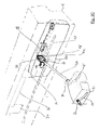
- FIG 1 illustrates, in perspective view, an embodiment of the invention in which a roof portion device 10 (which may also be referred to hereinafter as a "flush flag") comprises a fixed glazing panel 11 pierced with an opening 12, and a movable glazing panel 13 (shown in partial open position of about 30%) sliding relative to this fixed panel.
- a roof portion device 10 which may also be referred to hereinafter as a "flush flag”
- a fixed glazing panel 11 pierced with an opening 12
- a movable glazing panel 13 shown in partial open position of about 30%
- the glazed fixed panel 11 for example tempered glass, can be curved, to give the pavilion a shape meeting the current criteria in terms of design, and air penetration.
- the outer contour of this panel 11 is secured in a flush manner, by gluing and / or by any other suitable securing means, to a receiving edge 14 defined on the bodywork.
- the sliding glazing panel 13 made for example of thermoformed polycarbonate, and provided with a functional frame extending on its contour, on the side facing the inside of the vehicle, is guided relative to the fixed panel 11 by rails 15 and 16.
- These rails 15 and 16 are attached, for example by gluing, welding, screwing or any other suitable technique, on the face of the fixed glazing panel turned towards the inside of the vehicle. They are placed on either side of the opening 12, outside the area of the outer contour of the panel 11, so as not to interfere with the receiving edge of the fixed panel provided behind the body, during assembly and gluing this panel to the body.
- the rails 15 and 16 have extensions, or retaining elements, extending substantially to the receiving edge 14 so that the ends of the rails can be secured to the receiving border on the bodywork to enhance safety and meet the standard requirements for broken glass panels, and in this case the fixed glass panel 11.
- Two (or more) retaining elements are thus reported between each of the rails and the edge of the nearest corresponding bodywork, perpendicular to the rails. It may also be extensions formed in the mass of the rail, in a variant of this embodiment. In any case, these retaining elements make it possible to retain the rails 15 and 16, and the movable glass panel 13 that they carry, even if the glazed fixed panel 11 which carries these elements is destroyed, thus protecting the occupants of the inside the vehicle.
- the movable glazing panel 13 can slide while being guided in the rails 15 and 16 in a substantially horizontal direction, in a sliding plane, substantially parallel to the plane of the roof portion 10, between one or more position (s) of opening and an intermediate position of release in which it is opposite the opening and cleared thereof.
- a displacement, perpendicular to the plane formed by the fixed panel 11, allows the passage of the glazed movable panel from the intermediate release position in which it is unlocked, to a closed and locked position, in which the glazed movable panel is located in the same plane as the fixed panel 11, and closes the opening 12.
- This vertical embedding movement is advantageous because it allows to press uniformly the seal disposed between the panel frame mobile 13 and the fixed panel 11, which reduces the risk of occurrence of sealing defects.
- the movement of the mobile glass panel can follow a curve according to which the two movements (locking / unlocking and sliding) are linked.
- a retractable baffle screen 17 is furthermore deployed in front of the opening 12 (that is to say on the side corresponding to the front of the vehicle), in this open position.
- the deflector system 20 of the roof portion 10 comprises a deflector screen 17 carried by three supports (in this particular embodiment), two lateral supports 21 and a central support 22. These supports 21, 22 are fixed, by gluing in this embodiment, on the inner face of the fixed panel 11 turned towards the inside of the vehicle.
- the lateral supports 21 are arranged symmetrically with respect to the central support 22.
- the central support 22 is advantageously offset towards the front of the vehicle with respect to the lateral supports 21.
- the screen 17, which is a rigid piece, has three tabs 23 each clipped on a tube 24 passing through a curved hole 25 formed in one of the supports 21, 22.
- each tab has a clipped fork on the corresponding tube 24 on three sections, respectively on either side of the support and in an intermediate section at a groove formed in the support.
- connection between the screen and the supports are of course conceivable.
- the baffle screen is detachable in this embodiment of the invention, which allows for example to facilitate its replacement if it were to be damaged.
- the rod 27 is for example made of piano wire or plastic.
- This axis 26 makes it possible to push or pull the screen 17, through the tubes which are guided in the slots 25, to make it pass from a retracted position, in which it is housed inside the cockpit against the supports 21 and 22, at a partial deployed position (as shown in FIG. figure 2 ) or complete when the opening 12 is released more than 60%, in this embodiment of the invention, and vice versa. Due to the shift of the central support 22 relative to the supports 21, the screen 17 is driven without being able to pivot.
- the curvature of the lights 25 also allows to gradually recover during deployment, or reciprocally gradually fold the screen when it is retracted.
- the surface of the deflector screen also masks the supports, which is aesthetic.
- the operation of the screen 17 of the deflector system 20 is obtained by controlling the displacement of the end 28 of the axis 26.
- the securing of the end 28 to the shuttle 31 is carried out by means of a lever forming a latch 33 pivotally mounted about an axis 333 on the shuttle 31, to a first arm 331 of which the end 28 is hinged .
- the shuttle 31 is held forward, abutting against a transverse wall of the rail, by a first overmolded pin 34 on a strand of a push-pull cable 35 for actuating the sliding glazing panel connected to a motorcycle -reducer (not shown).
- This lug 34 is pressed against a housing 36 of a spring 37, fixed at one end to the shuttle, which it keeps compressed.
- This housing 36 prevents buckling of the spring, and provides a good support on the lug and the lock, depending on the positions.
- the cable strand 35 which extends towards the rear of the vehicle, is housed in a second inner guiding slide formed in the rail 16.
- the housing 36 which follows the movement of the lug 34 also retreats under the thrust of the spring 37, which decompresses gradually.
- This phase makes it possible to achieve a time shift between the position of the deflector screen, which remains stationary during this phase, and the position of the sliding panel, which has been unlocked and has begun to slide backwards, for example in a movement tacking.
- the screen will reach an extended position, in which it protrudes out of the vehicle to a maximum, by a substantially swaying movement.
- the tubes 24 are in abutment against the rear end of the slots 25, which blocks the rearward movement of the shuttle.
- the lever 33 By moving the cable 35 to the rear to continue opening the movable panel, the lever 33 will gradually tilt up under the action exerted on the arm 39, the lug 34. The lug will therefore cross the lever and continue moving towards the rear of the vehicle with the sliding glass panel.
- the finger 28, which is secured to the arm 331 of the lever 33, will then straighten vertically, guided in the oblong slot 312 of the shuttle, which prevents any return of the deflector screen in the retracted position, since the finger does not found more in front of the groove 29. It should be noted that to allow this movement of the finger, it is housed movable in an oblong groove formed on the first arm 331.
- the lug 34 progressing towards the front of the vehicle will push the housing 36, which through the spring 37 will communicate to the shuttle 31 a forward displacement.
- the screen 17 driven by the shuttle will gradually slide under the fixed glass panel into the retracted position, leaving the passage to the mobile glass panel 13 under the opening 12 (FIG. figure 1 ).
- the cable 35 at the end of stroke will lock the screen in the retracted position, keeping the spring 37 compressed under the pressure of the lug 34.
- This device 40 consists of a fixed glazed panel 41, having an opening 42, of a movable glazing panel 43 slidable relative to the fixed panel 41 in rails 44 (only the rail on the right side of the vehicle is shown on these figures), and a retractable baffle shield 45 to limit the effects of air flapping.
- the movable panel 43 is driven by a "push-pull" cable (not shown) attached thereto.
- a detail of the area near the front end of the rail 44 is shown sideways on the Figure 5A and from below on the Figure 5B in a position where the deflector screen is fully deployed.
- the deflector screen 45 has, on each of its sides, two guide fingers 51 and 52, which protrude laterally, through the parallel curved lights 53 and 54 formed in a corresponding lateral support 55, fixed on the inner face of the fixed panel 41, and penetrate inside the hollow rail 44.
- This support 55 has a shoulder 551 on which bears the finger 52.
- no central support is provided in this second embodiment.
- a single curved light may be provided to guide the deflector screen.
- a transmission link 56 is rotatably mounted on the end of the finger 51.
- the other end 561 of this link 56 is articulated to a locking pad 57 of the screen around an axis 571.
- the end 561 of the rod has been bent upwards and the pad 57 has been hollowed out on its portion 572.
- a traction spring 514 is housed in the rail 44, one of its ends being fixed to the shoe 57 and the other end to the rail 44.
- the shoe 57 is disengaged from the movable panel 43 and is stationary in the rail 44, since it is not biased by the spring 514. Therefore, the deflector screen 45 is also immobilized in the deployed position , since a connection exists, via the rod 56, between the deflector screen 45 and the locking shoe, and that the screen can not switch because two fingers are used to guide each of its ratings.
- each of the lights 53 and 54 has been provided at the rear end of each of the lights 53 and 54 a recess forming a cradle 71, 72, having a notch shape and illustrated figure 7 .
- This recess ensures that the deflector maintains the deployed position if a force is exerted on the deflector in the vertical direction, for example by the action of the wind or in the case where a person or an object placed on the flag supports on the baffle.
- the baffle screen is locked in its central part with a striker 46 fixed to the fixed panel of the roof in which two short pins 47, 48 or bolts, formed on the deflector screen, catch.
- this pad has a finger 513 penetrating into a rectilinear slot 512 formed on the side turned towards the outside of the vehicle, which guides it during its sliding in the slide portion 515 and prevents its bracing.
- the screen 45 will therefore also progressively retract under the fixed panel, the rod 56 transmitting to the finger 51 the amplitude of movement of the pad 57 in the direction of the rail. It is recalled that, simultaneously, the curvature of the lights 51 and 52 makes it possible to tilt the deflector screen 45 and thus to straighten or gradually fold this screen when moving towards the rear or towards the front of the vehicle.
- the device 40 makes it possible to index the position of the screen 45 to that of the mobile panel 43.
Landscapes
- Engineering & Computer Science (AREA)
- Mechanical Engineering (AREA)
- Body Structure For Vehicles (AREA)
- Power-Operated Mechanisms For Wings (AREA)
Applications Claiming Priority (1)
| Application Number | Priority Date | Filing Date | Title |
|---|---|---|---|
| FR0950340 | 2009-01-20 |
Publications (3)
| Publication Number | Publication Date |
|---|---|
| EP2208628A2 true EP2208628A2 (de) | 2010-07-21 |
| EP2208628A3 EP2208628A3 (de) | 2010-10-06 |
| EP2208628B1 EP2208628B1 (de) | 2013-06-26 |
Family
ID=42154258
Family Applications (1)
| Application Number | Title | Priority Date | Filing Date |
|---|---|---|---|
| EP20090165792 Not-in-force EP2208628B1 (de) | 2009-01-20 | 2009-07-17 | Vorrichtung, die den verglasten Anteil eines Kraftfahrzeugdachs bildet und mit einem Abweiser ausgestattet ist |
Country Status (1)
| Country | Link |
|---|---|
| EP (1) | EP2208628B1 (de) |
Cited By (2)
| Publication number | Priority date | Publication date | Assignee | Title |
|---|---|---|---|---|
| WO2016008938A1 (fr) * | 2014-07-15 | 2016-01-21 | Advanced Comfort Systems France Sas - Acs France | Pavillon vitre a panneau mobile controle par des navettes |
| CN113286720A (zh) * | 2018-12-21 | 2021-08-20 | 宝适汽车部件(太仓)有限公司 | 用于机动车的能够打开的车顶截取区段的挡风设备 |
Citations (1)
| Publication number | Priority date | Publication date | Assignee | Title |
|---|---|---|---|---|
| WO2008068325A1 (fr) | 2006-12-06 | 2008-06-12 | Wagon Sas | Pavillon vitré de véhicule automobile, procédé de montage et véhicule correspondants |
Family Cites Families (4)
| Publication number | Priority date | Publication date | Assignee | Title |
|---|---|---|---|---|
| US4362332A (en) * | 1981-03-26 | 1982-12-07 | General Motors Corporation | Sunroof air deflector |
| DE3916906C1 (de) * | 1989-05-24 | 1990-06-28 | Webasto Ag Fahrzeugtechnik, 8035 Stockdorf, De | |
| DE10146285B4 (de) * | 2001-03-19 | 2007-03-29 | Webasto Ag | Fahrzeugdach |
| DE10217147C1 (de) * | 2002-04-17 | 2003-10-16 | Webasto Vehicle Sys Int Gmbh | Windabweiser für öffnungsfähige Fahrzeugdächer |
-
2009
- 2009-07-17 EP EP20090165792 patent/EP2208628B1/de not_active Not-in-force
Patent Citations (1)
| Publication number | Priority date | Publication date | Assignee | Title |
|---|---|---|---|---|
| WO2008068325A1 (fr) | 2006-12-06 | 2008-06-12 | Wagon Sas | Pavillon vitré de véhicule automobile, procédé de montage et véhicule correspondants |
Cited By (4)
| Publication number | Priority date | Publication date | Assignee | Title |
|---|---|---|---|---|
| WO2016008938A1 (fr) * | 2014-07-15 | 2016-01-21 | Advanced Comfort Systems France Sas - Acs France | Pavillon vitre a panneau mobile controle par des navettes |
| FR3023752A1 (fr) * | 2014-07-15 | 2016-01-22 | Acs France Sas | Pavillon vitre a panneau mobile controle par des navettes |
| CN113286720A (zh) * | 2018-12-21 | 2021-08-20 | 宝适汽车部件(太仓)有限公司 | 用于机动车的能够打开的车顶截取区段的挡风设备 |
| CN113286720B (zh) * | 2018-12-21 | 2023-03-24 | 宝适汽车部件(太仓)有限公司 | 用于机动车的能够打开的车顶截取区段的挡风设备 |
Also Published As
| Publication number | Publication date |
|---|---|
| EP2208628A3 (de) | 2010-10-06 |
| EP2208628B1 (de) | 2013-06-26 |
Similar Documents
| Publication | Publication Date | Title |
|---|---|---|
| EP1659247B1 (de) | Schliesseinrichtung einer Öffnung mittels einer beweglichen Scheibe mit an der Bewegung beteiligten Verriegelungsmitteln, und zugehöriges Fahrzeug | |
| EP1916132B1 (de) | Verriegelungsvorrichtung mit Drückergriff und Hebel für Schiebepaneel eines Kraftfahrzeugs, entsprechende Verschlussvorrichtung und entsprechendes Kraftfahrzeug | |
| EP3022076B1 (de) | Vorrichtung zum verschliessen eines raums eines kraftfahrzeugs mit einem schiebepaneel mit einem griff und parallel zu schiebeachse und zahnrädern bewegbar sowie entsprechendes fahrzeug | |
| FR3072640A1 (fr) | Diffuseur arriere mobile de vehicule automobile a panneaux multiples | |
| EP2196341B1 (de) | Vorrichtung zur Abdichtung eines Öffnungsfeldes eines Kraftfahrzeugs mit Hilfe eines Schiebepaneels, und entsprechendes Kraftfahrzeug | |
| EP3027446B1 (de) | Schliessvorrichtung für ein fahrzeugdach mit einer beweglichen platte und einem drehbaren hebel, sowie entsprechendes fahrzeug | |
| EP1666302A1 (de) | Umstellbare Armlehne für Kraftfahrzeuge | |
| EP2208628B1 (de) | Vorrichtung, die den verglasten Anteil eines Kraftfahrzeugdachs bildet und mit einem Abweiser ausgestattet ist | |
| FR2644406A1 (fr) | Unite d'equipement pour toits ouvrants pour vehicules automobiles | |
| EP2010405A1 (de) | Vorrichtung zum verriegeln eines versenkbaren dachs und mit solch einem system ausgestattetes fahrzeug | |
| EP1644213B1 (de) | Schiebedachsystem mit stapelbaren platten und damit ausgestattetes fahrzeug | |
| EP3055149B1 (de) | Vorrichtung zum verschliessen einer fahrzeugöffnung mit einer verschiebbaren platte, mit einem griff bewegbar in verschieberichtung und mit flexiblen lamellen, und entsprechendes fahrzeug | |
| FR2893074A1 (fr) | Porte de vehicule automobile a panneau vitre coulissant, et vehicule correspondant. | |
| FR2890006A1 (fr) | Vehicule automobile a toit escamotable. | |
| EP2457756B1 (de) | Verglaster Pavillon mit beweglichen Schiebe- und Öffnungspaneelen | |
| FR2936981A1 (fr) | Dispositif de toit ouvrant a commande manuelle pour vehicule notamment de type automobile | |
| EP1700727B1 (de) | Sonnenschutz für ein Motorfahrzeug, mit komplementärem Schutz und korrespondierendes Motorfahrzeug | |
| EP1800924B1 (de) | KFZ mit Sonnenblende, die in einem in Längsrichtung verlaufenden mittigen Dachholm verstaut wird | |
| FR2983129A1 (fr) | Pavillon vitre a panneau mobile coulissant et entrebaillant. | |
| FR2881687A1 (fr) | Dispositif d'occultation pour pavillon vitre a actionnement manuel ou electrique | |
| FR2905900A1 (fr) | Ensemble de guidage d'elements de couverture d'un habitacle d'un vehicule automobile | |
| FR2985227A1 (fr) | Pavillon vitre de vehicule automobile equipe d'un deflecteur, et vehicule correspondant | |
| FR2961130A1 (fr) | Toit souple repliable pour vehicule automobile. | |
| FR2834674A1 (fr) | Systeme de deflecteur de toit ouvrant | |
| FR2965224A1 (fr) | Vehicule automobile comportant un toit escamotable constitue d'un panneau avant et d'une lunette arriere mobiles. |
Legal Events
| Date | Code | Title | Description |
|---|---|---|---|
| PUAI | Public reference made under article 153(3) epc to a published international application that has entered the european phase |
Free format text: ORIGINAL CODE: 0009012 |
|
| AK | Designated contracting states |
Kind code of ref document: A2 Designated state(s): AT BE BG CH CY CZ DE DK EE ES FI FR GB GR HR HU IE IS IT LI LT LU LV MC MK MT NL NO PL PT RO SE SI SK SM TR |
|
| PUAL | Search report despatched |
Free format text: ORIGINAL CODE: 0009013 |
|
| AK | Designated contracting states |
Kind code of ref document: A3 Designated state(s): AT BE BG CH CY CZ DE DK EE ES FI FR GB GR HR HU IE IS IT LI LT LU LV MC MK MT NL NO PL PT RO SE SI SK SM TR |
|
| RAP1 | Party data changed (applicant data changed or rights of an application transferred) |
Owner name: ADVANCED COMFORT SYSTEMS FRANCE SAS - ACS FRANCE |
|
| 17P | Request for examination filed |
Effective date: 20110325 |
|
| GRAP | Despatch of communication of intention to grant a patent |
Free format text: ORIGINAL CODE: EPIDOSNIGR1 |
|
| GRAP | Despatch of communication of intention to grant a patent |
Free format text: ORIGINAL CODE: EPIDOSNIGR1 |
|
| INTG | Intention to grant announced |
Effective date: 20130326 |
|
| GRAS | Grant fee paid |
Free format text: ORIGINAL CODE: EPIDOSNIGR3 |
|
| GRAA | (expected) grant |
Free format text: ORIGINAL CODE: 0009210 |
|
| AK | Designated contracting states |
Kind code of ref document: B1 Designated state(s): AT BE BG CH CY CZ DE DK EE ES FI FR GB GR HR HU IE IS IT LI LT LU LV MC MK MT NL NO PL PT RO SE SI SK SM TR |
|
| REG | Reference to a national code |
Ref country code: GB Ref legal event code: FG4D Free format text: NOT ENGLISH |
|
| REG | Reference to a national code |
Ref country code: CH Ref legal event code: EP |
|
| REG | Reference to a national code |
Ref country code: AT Ref legal event code: REF Ref document number: 618535 Country of ref document: AT Kind code of ref document: T Effective date: 20130715 |
|
| REG | Reference to a national code |
Ref country code: IE Ref legal event code: FG4D Free format text: LANGUAGE OF EP DOCUMENT: FRENCH |
|
| REG | Reference to a national code |
Ref country code: DE Ref legal event code: R096 Ref document number: 602009016648 Country of ref document: DE Effective date: 20130822 |
|
| PG25 | Lapsed in a contracting state [announced via postgrant information from national office to epo] |
Ref country code: LT Free format text: LAPSE BECAUSE OF FAILURE TO SUBMIT A TRANSLATION OF THE DESCRIPTION OR TO PAY THE FEE WITHIN THE PRESCRIBED TIME-LIMIT Effective date: 20130626 Ref country code: SI Free format text: LAPSE BECAUSE OF FAILURE TO SUBMIT A TRANSLATION OF THE DESCRIPTION OR TO PAY THE FEE WITHIN THE PRESCRIBED TIME-LIMIT Effective date: 20130626 Ref country code: SE Free format text: LAPSE BECAUSE OF FAILURE TO SUBMIT A TRANSLATION OF THE DESCRIPTION OR TO PAY THE FEE WITHIN THE PRESCRIBED TIME-LIMIT Effective date: 20130626 Ref country code: FI Free format text: LAPSE BECAUSE OF FAILURE TO SUBMIT A TRANSLATION OF THE DESCRIPTION OR TO PAY THE FEE WITHIN THE PRESCRIBED TIME-LIMIT Effective date: 20130626 Ref country code: NO Free format text: LAPSE BECAUSE OF FAILURE TO SUBMIT A TRANSLATION OF THE DESCRIPTION OR TO PAY THE FEE WITHIN THE PRESCRIBED TIME-LIMIT Effective date: 20130926 Ref country code: GR Free format text: LAPSE BECAUSE OF FAILURE TO SUBMIT A TRANSLATION OF THE DESCRIPTION OR TO PAY THE FEE WITHIN THE PRESCRIBED TIME-LIMIT Effective date: 20130927 |
|
| REG | Reference to a national code |
Ref country code: AT Ref legal event code: MK05 Ref document number: 618535 Country of ref document: AT Kind code of ref document: T Effective date: 20130626 |
|
| REG | Reference to a national code |
Ref country code: LT Ref legal event code: MG4D |
|
| PG25 | Lapsed in a contracting state [announced via postgrant information from national office to epo] |
Ref country code: BG Free format text: LAPSE BECAUSE OF FAILURE TO SUBMIT A TRANSLATION OF THE DESCRIPTION OR TO PAY THE FEE WITHIN THE PRESCRIBED TIME-LIMIT Effective date: 20130926 Ref country code: HR Free format text: LAPSE BECAUSE OF FAILURE TO SUBMIT A TRANSLATION OF THE DESCRIPTION OR TO PAY THE FEE WITHIN THE PRESCRIBED TIME-LIMIT Effective date: 20130626 |
|
| REG | Reference to a national code |
Ref country code: NL Ref legal event code: VDEP Effective date: 20130626 |
|
| PG25 | Lapsed in a contracting state [announced via postgrant information from national office to epo] |
Ref country code: LV Free format text: LAPSE BECAUSE OF FAILURE TO SUBMIT A TRANSLATION OF THE DESCRIPTION OR TO PAY THE FEE WITHIN THE PRESCRIBED TIME-LIMIT Effective date: 20130626 |
|
| BERE | Be: lapsed |
Owner name: ADVANCED COMFORT SYSTEMS FRANCE SAS - ACS FRANCE Effective date: 20130731 |
|
| PG25 | Lapsed in a contracting state [announced via postgrant information from national office to epo] |
Ref country code: SK Free format text: LAPSE BECAUSE OF FAILURE TO SUBMIT A TRANSLATION OF THE DESCRIPTION OR TO PAY THE FEE WITHIN THE PRESCRIBED TIME-LIMIT Effective date: 20130626 Ref country code: IS Free format text: LAPSE BECAUSE OF FAILURE TO SUBMIT A TRANSLATION OF THE DESCRIPTION OR TO PAY THE FEE WITHIN THE PRESCRIBED TIME-LIMIT Effective date: 20131026 Ref country code: CY Free format text: LAPSE BECAUSE OF FAILURE TO SUBMIT A TRANSLATION OF THE DESCRIPTION OR TO PAY THE FEE WITHIN THE PRESCRIBED TIME-LIMIT Effective date: 20130904 Ref country code: PT Free format text: LAPSE BECAUSE OF FAILURE TO SUBMIT A TRANSLATION OF THE DESCRIPTION OR TO PAY THE FEE WITHIN THE PRESCRIBED TIME-LIMIT Effective date: 20131028 Ref country code: CZ Free format text: LAPSE BECAUSE OF FAILURE TO SUBMIT A TRANSLATION OF THE DESCRIPTION OR TO PAY THE FEE WITHIN THE PRESCRIBED TIME-LIMIT Effective date: 20130626 Ref country code: AT Free format text: LAPSE BECAUSE OF FAILURE TO SUBMIT A TRANSLATION OF THE DESCRIPTION OR TO PAY THE FEE WITHIN THE PRESCRIBED TIME-LIMIT Effective date: 20130626 Ref country code: EE Free format text: LAPSE BECAUSE OF FAILURE TO SUBMIT A TRANSLATION OF THE DESCRIPTION OR TO PAY THE FEE WITHIN THE PRESCRIBED TIME-LIMIT Effective date: 20130626 |
|
| PG25 | Lapsed in a contracting state [announced via postgrant information from national office to epo] |
Ref country code: ES Free format text: LAPSE BECAUSE OF FAILURE TO SUBMIT A TRANSLATION OF THE DESCRIPTION OR TO PAY THE FEE WITHIN THE PRESCRIBED TIME-LIMIT Effective date: 20131007 Ref country code: PL Free format text: LAPSE BECAUSE OF FAILURE TO SUBMIT A TRANSLATION OF THE DESCRIPTION OR TO PAY THE FEE WITHIN THE PRESCRIBED TIME-LIMIT Effective date: 20130626 Ref country code: RO Free format text: LAPSE BECAUSE OF FAILURE TO SUBMIT A TRANSLATION OF THE DESCRIPTION OR TO PAY THE FEE WITHIN THE PRESCRIBED TIME-LIMIT Effective date: 20130626 Ref country code: NL Free format text: LAPSE BECAUSE OF FAILURE TO SUBMIT A TRANSLATION OF THE DESCRIPTION OR TO PAY THE FEE WITHIN THE PRESCRIBED TIME-LIMIT Effective date: 20130626 |
|
| REG | Reference to a national code |
Ref country code: CH Ref legal event code: PL |
|
| PG25 | Lapsed in a contracting state [announced via postgrant information from national office to epo] |
Ref country code: CY Free format text: LAPSE BECAUSE OF FAILURE TO SUBMIT A TRANSLATION OF THE DESCRIPTION OR TO PAY THE FEE WITHIN THE PRESCRIBED TIME-LIMIT Effective date: 20130626 Ref country code: MC Free format text: LAPSE BECAUSE OF FAILURE TO SUBMIT A TRANSLATION OF THE DESCRIPTION OR TO PAY THE FEE WITHIN THE PRESCRIBED TIME-LIMIT Effective date: 20130626 |
|
| REG | Reference to a national code |
Ref country code: IE Ref legal event code: MM4A |
|
| PG25 | Lapsed in a contracting state [announced via postgrant information from national office to epo] |
Ref country code: DK Free format text: LAPSE BECAUSE OF FAILURE TO SUBMIT A TRANSLATION OF THE DESCRIPTION OR TO PAY THE FEE WITHIN THE PRESCRIBED TIME-LIMIT Effective date: 20130626 Ref country code: CH Free format text: LAPSE BECAUSE OF NON-PAYMENT OF DUE FEES Effective date: 20130731 Ref country code: BE Free format text: LAPSE BECAUSE OF NON-PAYMENT OF DUE FEES Effective date: 20130731 Ref country code: LI Free format text: LAPSE BECAUSE OF NON-PAYMENT OF DUE FEES Effective date: 20130731 |
|
| PLBE | No opposition filed within time limit |
Free format text: ORIGINAL CODE: 0009261 |
|
| STAA | Information on the status of an ep patent application or granted ep patent |
Free format text: STATUS: NO OPPOSITION FILED WITHIN TIME LIMIT |
|
| GBPC | Gb: european patent ceased through non-payment of renewal fee |
Effective date: 20130926 |
|
| PG25 | Lapsed in a contracting state [announced via postgrant information from national office to epo] |
Ref country code: IT Free format text: LAPSE BECAUSE OF FAILURE TO SUBMIT A TRANSLATION OF THE DESCRIPTION OR TO PAY THE FEE WITHIN THE PRESCRIBED TIME-LIMIT Effective date: 20130626 |
|
| 26N | No opposition filed |
Effective date: 20140327 |
|
| REG | Reference to a national code |
Ref country code: DE Ref legal event code: R097 Ref document number: 602009016648 Country of ref document: DE Effective date: 20140327 |
|
| PG25 | Lapsed in a contracting state [announced via postgrant information from national office to epo] |
Ref country code: IE Free format text: LAPSE BECAUSE OF NON-PAYMENT OF DUE FEES Effective date: 20130717 Ref country code: GB Free format text: LAPSE BECAUSE OF NON-PAYMENT OF DUE FEES Effective date: 20130926 |
|
| PG25 | Lapsed in a contracting state [announced via postgrant information from national office to epo] |
Ref country code: SM Free format text: LAPSE BECAUSE OF FAILURE TO SUBMIT A TRANSLATION OF THE DESCRIPTION OR TO PAY THE FEE WITHIN THE PRESCRIBED TIME-LIMIT Effective date: 20130626 |
|
| REG | Reference to a national code |
Ref country code: FR Ref legal event code: PLFP Year of fee payment: 7 |
|
| PG25 | Lapsed in a contracting state [announced via postgrant information from national office to epo] |
Ref country code: TR Free format text: LAPSE BECAUSE OF FAILURE TO SUBMIT A TRANSLATION OF THE DESCRIPTION OR TO PAY THE FEE WITHIN THE PRESCRIBED TIME-LIMIT Effective date: 20130626 Ref country code: MT Free format text: LAPSE BECAUSE OF FAILURE TO SUBMIT A TRANSLATION OF THE DESCRIPTION OR TO PAY THE FEE WITHIN THE PRESCRIBED TIME-LIMIT Effective date: 20130626 |
|
| PG25 | Lapsed in a contracting state [announced via postgrant information from national office to epo] |
Ref country code: LU Free format text: LAPSE BECAUSE OF NON-PAYMENT OF DUE FEES Effective date: 20130717 Ref country code: HU Free format text: LAPSE BECAUSE OF FAILURE TO SUBMIT A TRANSLATION OF THE DESCRIPTION OR TO PAY THE FEE WITHIN THE PRESCRIBED TIME-LIMIT; INVALID AB INITIO Effective date: 20090717 Ref country code: MK Free format text: LAPSE BECAUSE OF FAILURE TO SUBMIT A TRANSLATION OF THE DESCRIPTION OR TO PAY THE FEE WITHIN THE PRESCRIBED TIME-LIMIT Effective date: 20130626 |
|
| PGFP | Annual fee paid to national office [announced via postgrant information from national office to epo] |
Ref country code: FR Payment date: 20150624 Year of fee payment: 7 |
|
| PGFP | Annual fee paid to national office [announced via postgrant information from national office to epo] |
Ref country code: DE Payment date: 20150709 Year of fee payment: 7 |
|
| REG | Reference to a national code |
Ref country code: DE Ref legal event code: R119 Ref document number: 602009016648 Country of ref document: DE |
|
| PG25 | Lapsed in a contracting state [announced via postgrant information from national office to epo] |
Ref country code: FR Free format text: LAPSE BECAUSE OF NON-PAYMENT OF DUE FEES Effective date: 20160801 Ref country code: DE Free format text: LAPSE BECAUSE OF NON-PAYMENT OF DUE FEES Effective date: 20170201 |
|
| REG | Reference to a national code |
Ref country code: FR Ref legal event code: ST Effective date: 20170331 |