EP1594247A2 - Verfahren und Gerät zur Bestimmung von Ratenanpassungsparametern für einen Transportkanal in einem Mobiltelekommunikationssystem - Google Patents
Verfahren und Gerät zur Bestimmung von Ratenanpassungsparametern für einen Transportkanal in einem Mobiltelekommunikationssystem Download PDFInfo
- Publication number
- EP1594247A2 EP1594247A2 EP05009833A EP05009833A EP1594247A2 EP 1594247 A2 EP1594247 A2 EP 1594247A2 EP 05009833 A EP05009833 A EP 05009833A EP 05009833 A EP05009833 A EP 05009833A EP 1594247 A2 EP1594247 A2 EP 1594247A2
- Authority
- EP
- European Patent Office
- Prior art keywords
- channel
- transport channel
- transport
- size
- data
- Prior art date
- Legal status (The legal status is an assumption and is not a legal conclusion. Google has not performed a legal analysis and makes no representation as to the accuracy of the status listed.)
- Withdrawn
Links
Images


Classifications
-
- H—ELECTRICITY
- H04—ELECTRIC COMMUNICATION TECHNIQUE
- H04L—TRANSMISSION OF DIGITAL INFORMATION, e.g. TELEGRAPHIC COMMUNICATION
- H04L1/00—Arrangements for detecting or preventing errors in the information received
- H04L1/004—Arrangements for detecting or preventing errors in the information received by using forward error control
- H04L1/0056—Systems characterized by the type of code used
- H04L1/0067—Rate matching
- H04L1/0068—Rate matching by puncturing
-
- H—ELECTRICITY
- H04—ELECTRIC COMMUNICATION TECHNIQUE
- H04B—TRANSMISSION
- H04B7/00—Radio transmission systems, i.e. using radiation field
- H04B7/24—Radio transmission systems, i.e. using radiation field for communication between two or more posts
- H04B7/26—Radio transmission systems, i.e. using radiation field for communication between two or more posts at least one of which is mobile
- H04B7/2628—Radio transmission systems, i.e. using radiation field for communication between two or more posts at least one of which is mobile using code-division multiple access [CDMA] or spread spectrum multiple access [SSMA]
-
- H—ELECTRICITY
- H04—ELECTRIC COMMUNICATION TECHNIQUE
- H04L—TRANSMISSION OF DIGITAL INFORMATION, e.g. TELEGRAPHIC COMMUNICATION
- H04L1/00—Arrangements for detecting or preventing errors in the information received
- H04L1/12—Arrangements for detecting or preventing errors in the information received by using return channel
- H04L1/16—Arrangements for detecting or preventing errors in the information received by using return channel in which the return channel carries supervisory signals, e.g. repetition request signals
- H04L1/18—Automatic repetition systems, e.g. Van Duuren systems
- H04L1/1803—Stop-and-wait protocols
-
- H—ELECTRICITY
- H04—ELECTRIC COMMUNICATION TECHNIQUE
- H04L—TRANSMISSION OF DIGITAL INFORMATION, e.g. TELEGRAPHIC COMMUNICATION
- H04L1/00—Arrangements for detecting or preventing errors in the information received
- H04L1/12—Arrangements for detecting or preventing errors in the information received by using return channel
- H04L1/16—Arrangements for detecting or preventing errors in the information received by using return channel in which the return channel carries supervisory signals, e.g. repetition request signals
- H04L1/18—Automatic repetition systems, e.g. Van Duuren systems
- H04L1/1812—Hybrid protocols; Hybrid automatic repeat request [HARQ]
-
- H—ELECTRICITY
- H04—ELECTRIC COMMUNICATION TECHNIQUE
- H04L—TRANSMISSION OF DIGITAL INFORMATION, e.g. TELEGRAPHIC COMMUNICATION
- H04L1/00—Arrangements for detecting or preventing errors in the information received
- H04L1/12—Arrangements for detecting or preventing errors in the information received by using return channel
- H04L1/16—Arrangements for detecting or preventing errors in the information received by using return channel in which the return channel carries supervisory signals, e.g. repetition request signals
- H04L1/18—Automatic repetition systems, e.g. Van Duuren systems
- H04L1/1829—Arrangements specially adapted for the receiver end
- H04L1/1835—Buffer management
- H04L1/1845—Combining techniques, e.g. code combining
-
- H—ELECTRICITY
- H04—ELECTRIC COMMUNICATION TECHNIQUE
- H04L—TRANSMISSION OF DIGITAL INFORMATION, e.g. TELEGRAPHIC COMMUNICATION
- H04L1/00—Arrangements for detecting or preventing errors in the information received
- H04L1/0001—Systems modifying transmission characteristics according to link quality, e.g. power backoff
- H04L1/0002—Systems modifying transmission characteristics according to link quality, e.g. power backoff by adapting the transmission rate
- H04L1/0003—Systems modifying transmission characteristics according to link quality, e.g. power backoff by adapting the transmission rate by switching between different modulation schemes
-
- H—ELECTRICITY
- H04—ELECTRIC COMMUNICATION TECHNIQUE
- H04L—TRANSMISSION OF DIGITAL INFORMATION, e.g. TELEGRAPHIC COMMUNICATION
- H04L1/00—Arrangements for detecting or preventing errors in the information received
- H04L1/0001—Systems modifying transmission characteristics according to link quality, e.g. power backoff
- H04L1/0009—Systems modifying transmission characteristics according to link quality, e.g. power backoff by adapting the channel coding
Definitions
- the present invention relates to a code division multiple access (CDMA) communication system. More particularly, the present invention relates to a method and an apparatus for employing a hybrid automatic repeat request in an enhanced uplink dedicated transport channel.
- CDMA code division multiple access
- the universal mobile telecommunication service (UMTS) system which is a 3 rd generation mobile telecommunication system employing wideband code division multiple access (Wideband CDMA) based on the global system for mobile communication (GSM) and the general packet radio services (GPRS) (European telecommunication systems) provides consistent services in which users utilizing mobile phones or computers can transmit packet-based data, digitalized voice data, digitalized video data, and multimedia data at a high transmission rate of at least 2Mbps regardless of locations.
- the UMTS system employs the concept of virtual connection representing a packet-switched connection based on packet protocols such as the Internet protocol (IP) so as to always allow connection from any end point in a network.
- IP Internet protocol
- the UMTS system employs an enhanced uplink dedicated channel (EUDCH or E-DCH) such that the performance of packet transmission may be relatively improved in reverse link such as an uplink (UL) communication to a base station (BS) from a user equipment (UE).
- EUDCH enhanced uplink dedicated channel
- E-DCH supports techniques such as adaptive modulation and coding (AMC), hybrid automatic repeat request (HARQ), and base station control scheduling in order to provide relatively stable data transmission having a high speed.
- AMC adaptive modulation and coding
- HARQ hybrid automatic repeat request
- base station control scheduling in order to provide relatively stable data transmission having a high speed.
- the AMC provides a technique for raising the efficiency of resource usage by determining a modulation scheme and a coding scheme for a data channel according to channel states between the UE and the BS.
- the combination of the modulation scheme and the coding scheme is referred to as a modulation and coding scheme (MCS), and a variety of MCS levels may be defined depending on supportable combinations of the modulation scheme and the coding scheme.
- MCS modulation and coding scheme
- the AMC adaptively determines a MC level according to channel states between the UE and the BS so as to raise the efficiency of resource usage.
- the HARQ denotes a technique in which, when an initially-transmitted data packets are erroneous, data packets are re-transmitted in order to compensate for the erroneous data packets.
- the HARQ may be classified into a chase combining (CC) scheme for re-transmitting packets having the same formats as initially-transmitted packets when errors occur and an incremental redundancy (IR) scheme for re-transmitting packets having formats different from the formats of initially-transmitted packets when errors occur.
- CC chase combining
- IR incremental redundancy
- the base station control scheduling implies a scheme in which the BS determines an uplink data transmission state and the upper limit of possible data rates so as to transmit the determined information through a scheduling command to the UE, and the UE determines a possible data rate for an uplink E-DCH to be transmitted in consideration of the scheduling command when data are transmitted based on the E-DCH.
- FIG. 1 illustrates uplink packet transmission through E-DCHs 111 to 114 in a conventional wireless communication system.
- reference numeral 110 represents a base station (i.e., Node B) supporting the E-DCHs 111 to 114
- reference numerals 101 to 104 represent UEs which are using the E-DCHs 111 to 114.
- the UEs 101 to 104 transmit data to the Node B 110 through E-DCHs 111 to 114, respectively.
- the Node B 110 informs each UE of a state in which E-DCH data can be transmitted based on information regarding channel conditions, transmission rates of requested data, and states of data buffers of the UEs 101 to 104 using the E-DCHs 111 to 114.
- the Node B 100 performs scheduling in order to control E-DCH data transmission rates.
- the Node B 100 allocates high data transmission rates to UEs (e.g., UEs 101 and 102) close to the Node B 100 and low data transmission rates to UEs (e.g, UEs 103 and 104) far away from the Node B 100 while preventing a measurement noise rise value from exceeding a threshold value in order to improve overall system performance.
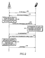
- FIG. 2 is a message flowchart for illustrating a transmit/receive process through the E-DCH.
- a Node B establishes an E-DCH channel with a UE.
- Step 202 comprises a step of delivering messages through a dedicated transport channel. If the E-DCH channel has been established, the UE reports scheduling information to the Node B in step 204.
- the scheduling information includes uplink channel information regarding transmit power of the UE, remaining power enabling transmission by the UE, an amount of data (to be transmitted) stacked in a buffer of the UE.
- the Node B having received scheduling information from a plurality of UEs (which are communicating with the Node B) monitors the scheduling information regarding the UEs in order to perform scheduling for data transmission of each UE in step 206. Specifically, the Node B determines the approval for uplink packet transmission by the UE and transmits scheduling assignment information to the UE in step 208.
- the scheduling assignment information includes information regarding allowed transmission timing and an allowed data transmission rate.
- the UE determines uplink E-DCH transport formats (TFs) based on the scheduling assignment information in step 210 and transmits uplink packet data and the TF information through an E-DCH to the Node B in steps 212 and 214.
- the TF information comprises a transport format resource indicator (TFRI) indicating resource information required for demodulating E-DCH data.
- TFRI transport format resource indicator
- the UE selects an MCS level based on a data rate assigned by the Node B and a channel state and transmits the uplink packet data based on the selected MCS level in step 214.
- the Node B determines if the TF information and the packet data are erroneous.
- the node B transmits NACK (Non-Acknowledge) information to the UE when at least one of the TF information and the packet data is erroneous as the determination result and transmits ACK (Acknowledge) information to the UE when both the TF information and the packet data have no errors.
- NACK Non-Acknowledge
- the ACK information is transmitted, packet data transmission is completed and the UE sends new user data through the E-DCH.
- the UE retransmits packet data having the same contents through the E-DCH.
- the E-DCH is matched with a single composite coded transport channel (CCTrCH) through transport channel multiplexing after rate matching in which repetition and puncturing are performed with respect to bits to be transmitted according to the number of bits that can be transmitted in a physical channel.
- CCTrCH composite coded transport channel
- the E-DCH supports a HARQ process performed in parallel. It is impossible to simply time-multiplex the E-DCH supporting HARQ employing both incremental redundancy (IR) and chase combining (CC) and the conventional DCH into a single CCTrCH because packets are transmitted with different bits each time they are retransmitted based on the HARQ IR. Therefore, it is necessary to distinguish dbetween rate matching patterns.
- the present invention has been made to solve the above-mentioned problems occurring in the prior art, and the present invention provides a method and an apparatus for time-multiplexing an enhanced uplink dedicated transport channel and a conventional dedicated transport channel into a single composite coded transport channel in a mobile telecommunication system.
- the present invention provides a method and an apparatus for supporting hybrid automatic repeat request (HARQ) in an enhanced uplink dedicated transport channel while multiplexing the enhanced uplink dedicated transport channel and a conventional dedicated transport channel into a single composite coded transport channel.
- HARQ hybrid automatic repeat request
- the present invention provides a method and an apparatus for supporting hybrid automatic repeat request (HARQ) based on incremental redundancy (IR) in an enhanced uplink dedicated transport channel.
- HARQ hybrid automatic repeat request
- IR incremental redundancy
- the present invention provides a method and an apparatus for determining rate matching parameters in an enhanced uplink dedicated transport channel such that the enhanced uplink dedicated transport channel may be time-multiplexed with a typical dedicated transport channel.
- a method for determining rate matching parameters for transport channels in a mobile telecommunication system comprising the steps of determining first physical channel bit sizes usable in transmitting at least one first transport channel not supporting hybrid automatic repeat request (HARQ) and at least one second transport channel supporting the hybrid automatic repeat request, determining if there is at least one second physical channel bit size in the first physical channel bit sizes, the second physical channel bit size allowing transmission for a size of coded bits corresponding to the first transport channel and a size of coded bits corresponding to the second transport channel in consideration of rate matching and puncturing, reducing the size of the coded bits corresponding to the second transport channel when the second physical channel bit size is not included in the first physical channel bit sizes, returning to the step of determining if there is at least one second physical channel bit size after the size of the coded bits corresponding to the second transport channel is reduced, and when there is at least one second physical channel bit size, selecting one second physical channel size based on at least one second physical channel bit size as a rate matching parameter for
- an apparatus for determining rate matching parameters for transport channels in a mobile telecommunication system comprising a rate matching parameter determination unit for reducing a size of coded bits corresponding to a second transport channel until there is at least one second physical channel bit size in first physical channel sizes, wherein the first physical channel bit sizes are available for transmitting at least one first transport channel and at least one second transport channel, the first transport channel not supporting hybrid automatic repeat request (HARQ) and the second transport channel supporting the hybrid automatic repeat request, the second physical channel bit size allowing transmission for a size of coded bits corresponding to the first transport channel and the size of the coded bits corresponding to the second transport channel in consideration of rate matching and puncturing, and selecting one second physical bit size based on at least one second physical channel bit size as a rate matching parameter for the first transport channel and the second transport channel when there is at least one second physical channel bit size, and a device for performing rate matching or rate de-matching by using the rate matching parameter.
- HARQ hybrid automatic repeat request
- rate matching parameters for an enhanced transport channel are determined such that the enhanced transport channel supporting hybrid automatic repeat request (HARQ) may be time-multiplexed with another transport channel not supporting the HARQ in a mobile telecommunication system supporting the HARQ based on both chase combining (CC) and incremental redundancy (IR).
- HARQ hybrid automatic repeat request
- CC chase combining
- IR incremental redundancy
- E-DCH enhanced uplink dedicated transport channel
- SAW HARQ Stop and Wait HARQ
- the SAW HARQ scheme additionally includes the following two schemes in order to improve the efficiency of a typical SAW ARQ scheme.
- the first scheme denotes a scheme in which erroneous data are temporarily stored, and then, the data are combined with retransmission data corresponding to the erroneous data so that error rates may be reduced. This process is referred to as soft combining.
- the soft combining has two schemes of chase combining (CC) and incremental redundancy (IR).
- a transmit side employs packets having the same formats in initial transmission and retransmission. If one code block including m symbols is transmitted in the initial transmission, symbols having the same number m are also transmitted in the retransmission. In other words, the same coding rates are employed for the initial transmission and the retransmission.
- a receive side combines an initial transmitted code block with a retransmitted code block based on a bit so as to decode the combined blocks and determines based on the decoded blocks if errors occur.
- the transmit side employs packets having different formats in initial transmission and retransmission.
- the transmit side transmits a code block including a portion of the m symbols in the initial transmission.
- code blocks including a portion of remaining symbols are sequentially transmitted. Accordingly, the initial transmission has a coding rate different from a coding rate of the retransmission.
- the received side provides a code block having a coding rate greater than coding rates of individually transmitted packets by concatenating the retransmitted symbols after the initially-transmitted symbols and then determines if errors occur by decoding the code block.
- the initial transmission and each retransmission are distinguished based on version numbers. Specifically, the initial transmission, the first retransmission, and the second retransmission are labeled as version 1, version 2, and version 3, respectively.
- the receive side concatenates the initially transmitted code block bits and the retransmitted code block bits in exact order by using the version information.
- UE establishes a plurality of logical HARQ channels with a Node B, identifies the channels based on specific time or a clarified channel number, and transmits packets through each channel.
- the receive side recognizes channels relating to packets received at a specific time point based on the identification information, rearranges the packets received through a plurality of HARQ channels in original sequence, and independently performs each HARQ process (e.g., soft combining) in each HARQ channel.
- each HARQ process e.g., soft combining
- the rate matching generally refers to an operation that bits in a transport block (a transmission unit on a transport channel) are punctured and repeated based on the size of bits in a physical frame (a transmission unit on a corresponding physical channel).
- the rate matching is performed through three steps including the determination of rate matching parameters, the determination of a rate matching pattern, and the execution of the rate matching.
- the number of bits to be punctured or repeated is calculated based on the number of bits which can be transmitted through a physical channel, and the rate matching parameters for determining the rate matching pattern are determined based on the calculated number of the bits.
- the rate matching pattern showing positions of bits in the transport block to be punctured or repeated is determined based on the determined rate matching parameters.
- a rate matching block is formed by puncturing or repeating bits of corresponding positions according to the rate matching pattern.
- the rate matching parameters are determined by means of rate matching parameter determination units in both UE and a Node B by using identical input information.
- the rate matching parameter determination unit calculates spreading factors and the number of codes of a physical channel to be used by the UE in step 301.
- an index of transport format combination TFC representing both the size of a transport block of each transport channel and the format of the transport channel is j
- the rate matching parameter determination unit determines the number of bits which can be processed by the physical layer, N data,j .
- possible N data values in the course of finding the N data,j are determined as ⁇ N 256 , N 128 , N 64 , N 32 , N 16 , N 8 , N 4 , 2 ⁇ N 4 , 3 ⁇ N 4 , 4 ⁇ N 4 , 5 ⁇ N 4 , 6 ⁇ N 4 ⁇ which is a set of the numbers of bits for spreading factors 256, 128, 64, 32, 16, 8, and 4.
- the N data values only one code (i.e., one physical channel) is employed for each of the spreading factors 256, 128, 64, 32, 16, and 8.
- one code to six codes may be employed for the spreading factor 4.
- the N 16 denotes the number of possible physical channel bits when a spreading factor is equal to 16
- the '6 ⁇ N 4 ' denotes the number of physical channel bits necessary for six physical channels when a spreading factor is equal to 4.
- SET 0 which is a sub-set of ⁇ N 256 , N 128 , N 64 , N 32 , N 16 , N 8 , N 4 , 2 ⁇ N 4 , 3 ⁇ N 4 , 4 ⁇ N 4 , 5 ⁇ N 4 , 6 ⁇ N 4 ⁇ is determined in order to find the N data,j .
- the SET 0 represents combinations spreading factors and physical channel bit sizes.
- the SET 0 denotes the set of the numbers of physical channel bits allowed by the UMTS terrestrial radio access network (UMTS) and supported by UE according to the capability of the UE.
- UMTS UMTS terrestrial radio access network
- SET 1 (which is a set including N data values satisfying Equation 1) is found based on the SET 0.
- the RM x denotes a rate matching attribute parameter corresponding to an x th TrCH (i.e., TrCH x ) and weight given for the x th TrCH.
- the I denotes the number of TrCHs to be multiplexed into one CCTrCH
- the N x,j denotes the number of coded bits included in a transport block of the TrCH x having the TFC j. Equation 1 is employed for preventing the occurrence of puncturing with respect to a TrCH having low weight.
- Equation 2 If the SET 1 obtained through Equation 1 is not an empty set and an element having the minimum value from among elements of the SET 1 requires only one physical channel (PhCH), the element having the minimum value is determined as the N data,j . If the SET 1 is an empty set and if the element having the minimum value requires at least two PhCHs, SET 2 (which is a set including N data values satisfying Equation 2) is found.
- the PL punctcturing limit
- the PL punctcturing limit
- the rate matching parameter determination unit sorts elements of the SET 2 obtained as described above in ascending order, analyzes the elements, and finds an element which does not have the maximum value in the SET2 and require an additional PhCH.
- the rate matching parameter determination unit finally determines the found element as the N data,j denoting the number of physical channel bits. In other words, under inevitable puncturing conditions, the rate matching parameter determination unit determines the N data,j in such a manner that the number of bits punctured within the preset PL or multi-code transmission is minimized.
- a spreading factor and the number of codes of a PhCH to be used by the UE are determined based on the N data,j .
- Equation 3 the Z 0,j and the Z i,j denote parameters defined only in Equation 3, and the value of the ⁇ denotes the maximum integer value which does not exceed the internal value.
- the ⁇ N i,j denotes an amount of bits to be punctured or repeated in each frame of an i th transport channel (i.e., TrCH i) having the TFC j.
- TrCH i transport channel
- the ⁇ N i,j denotes an amount of bits to be repeated
- the ⁇ N i,j denotes an amount of bits to be punctured.
- the N m,j represents the number of bits of TrCH m having the TFC j before rate matching. In other words, the N m,j denotes the number of coded bits of the TrCH m.
- the rate matching parameter determination unit calculates a rate matching pattern based on the ⁇ N i,j .
- the rate matching parameter determination unit calculates a rate matching pattern based on the ⁇ N i,j .
- the determination of the number of physical channel bits and the determination of the rate matching pattern are described.
- the number of E-DCH data bits may be more reduced in retransmission as compared with the number of E-DCH data bits in initial transmission which are different from the number of DCH data bits. Therefore, an operation of determining rate matching parameters, which enables multiplexing of the E-DCH supporting the HARQ and the DCH not supporting the HARQ, based on the HARQ characteristics is disclosed according to an embodiment of the present invention. Specifically, the number of physical channel bits (one of the rate matching parameters) is determined according to an embodiment of the present invention.
- FIG. 4 is a flowchart illustrating the operation of determining the number of physical channel bits according to an embodiment of the present invention.
- the number of physical channel bits to be employed for the DCH and the E-DCH, N data,j is found.
- the N data,j denoting the total number of the transmittable bits in a physical layer during one frame in a case of the TFC j is found.
- the operation of determining the number of physical channel bits is performed by the rate matching parameter determination unit for rate matchers of both the Node B and the UE.
- the rate matching parameter determination unit determines SET 0 denoting a set of the number of physical channel bits which can be used by the UE, such as ⁇ N 256 , N 128 , N 64 , N 32 , N 16 , N 8 , N 4 , 2 ⁇ N 4 , 3 ⁇ N 4 , 4 ⁇ N 4 , 5 ⁇ N 4 , 6 ⁇ N 4 ⁇ .
- the SET 0 may be determined through signaling from an upper layer when a call is established.
- elements belonging to the SET 0 are considered as N data values.
- the E-DCH is regarded as DCH k employing a transport block having N k,j number of coded bits.
- SET 1 is found by applying Equation 1 described above to the SET 0.
- the SET 1 denotes a set of the numbers of physical channel bits enabling rate matching while preventing puncturing.
- step 406 SET 2 denoting a set of N data s satisfying Equation 2 described above in the SET 1 is found.
- the SET 2 represents a set of the numbers of physical channel bits allowing transport channel data even when puncturing is performed based on the preset PL.
- the maximum number of bits to be punctured is equal to (1-PL)*100.
- step 407 it is determined if the SET 2 is an empty set. If the SET 2 is an empty set, step 412 is performed. Otherwise, step 408 is performed.
- step 409 the rate matching parameter determination unit determines if the initial N data is the maximum value in the SET 2.
- the fact that the initial N data is the maximum value in the SET 2 refers to the initial N data being a unique element in the SET 2.
- the rate matching parameter determination unit reduces the amount of punctured bits while preventing the increase of the number of PhCH codes by repeatedly performing step 409 to step 411 until the N data,j is determined as described above.
- the SET 2 is an empty set in step 407.
- the fact that the SET 2 is an empty set refers to the number of physical channel bits allowing transmission within the PL does not exist in the SET 0 due to the excessive number of bits of E-DCH data. Therefore, it is impossible to multiplex the DCH and the E-DCH. Accordingly, the DCH and the E-DCH can be multiplexed with puncturing within the PL by reducing the number of bits of the E-DCH data. This is because only a portion of the bits of the E-DCH data can be transmitted based on necessity due to the support of the E-DCH for the HARQ IR.
- the rate matching parameter determination unit reduces the N k,j according to a preset rule in order to calculate new SET 1 and new SET 2 in step 412 and then returns to step 403.
- two schemes for reducing the N k,j are as follows.
- the N k,j is reduced based on Equation 4.
- the N k,j ' denotes reduced N k,j .
- the N k,j is reduced at the preset ratio of the step_ratio.
- the step_ratio denotes a value previously agreed to between the Node B and the UE as a real number smaller than '1'.
- the N k,j ' is reduced by the step_size denoting the preset number of bits.
- the step_size implies a value previously agreed to between the Node Band the UE as an integer larger than '0'.
- N k,j (i.e., N k,j ') obtained through Equations 4 and 5 must satisfy Equation 6. Equation 6 N k , j ' ⁇ ⁇ ⁇ M E , j
- the ⁇ denotes an update limit ratio allowed by a system as a real number smaller than '1'. Accordingly, the total ratio for reducing the N k,j cannot exceed the update limit ratio ⁇ allowed by a system. Therefore, restriction conditions such as Equation 6 prevent the excessive puncturing for E-DCH output bits and the excessive increase of the number of retransmission due to the excessive puncturing.
- step 403 the rate matching parameter determination unit sets new SET 1 by using the N k,j '.
- the N k,j ' is used for setting new SET 2.
- the N data,j found through the steps is used for calculating ⁇ N k,j denoting an amount of bits to be punctured or repeated in each TrCH through Equation 3 described above.
- the amount of bits to be punctured or repeated based on the N k,j is the ⁇ N k,j .
- the N E,data,j is a sum of the N k,j and the ⁇ N k,j .
- a rate matching pattern for the DCH is determined according to a conventional rate matching algorithm based on the calculated bit amount
- a rate matching pattern for the E-DCH is determined according to an HARQ rate matching algorithm based on the calculated bit amount.
- the HARQ rate matching algorithm will be described.
- N E,data,j When the size of E-DCH transport blocks transmittable on a physical channel (PhCH) is N E,data,j , the N E,data,j is equal to a sum of the N k,j and the ⁇ N k,j .
- ⁇ M E,j denoting an amount of bits to be punctured or repeated in the E-DCH is equal to N E,data,j -M E,j .
- Rate matching parameters required for the HARQ rate matching algorithm are the N E,data,j , the M E,j , and s and r (which are redundancy version parameters). The N E,data,j from among these parameters is calculated as described above.
- the parameter r helps a value e ini used for a rate matching algorithm to be changed with respect to each HARQ transmission.
- the e ini denotes an initial value of a value e used in order to calculate an HARQ rate matching pattern.
- FIG. 5 illustrates a block diagram for HARQ rate matching according to an embodiment of the present invention.
- Input values of a HARQ matcher 500 are classified into systematic bits N t,sys , first parity bits N t,p1 , and second parity bits N t,p2 .
- the input bit streams are rate-matched by means of corresponding rate matchers 501, 502, and 503.
- the rate matchers 501, 502, and 503 perform repetition or puncturing with respect to input bit streams and output bit streams N t,sys , N t,p1 , and N t,p2 , respectively.
- FIG. 6 is a flowchart illustrating the operation of determining the rate matching parameters for the HARQ rate matching according to an embodiment of the present invention. The operation is performed by the rate matching parameter determination units of both the Node B and the UE.
- step 601 the rate matching parameter determination unit determines the sign of the ⁇ M E,j representing an amount of bits to be repeated or punctured in the E-DCH. If the sign is negative, the rate matching parameter determination unit determines to puncture the bits and performs step 602. If the sign is positive, the rate matching parameter determination unit determines to repeat the bits and performs step 607.
- the rate matching parameter determination unit finds the size of systematic bits output through HARQ rate matching in step 607.
- the rate matching parameter determination unit calculates the sizes of first parity bits and second parity bits output through HARQ rate matching in step 608. Then, the rate matching parameter determination unit finds the value e ini . in step 609.
- HSDPA High Speed Downlink Packet Access
- Values N sys , N p1 , and N p2 denote the sizes of systematic bits, first parity bits, and second parity bits input for HARQ rate matching processes, respectively.
- Values N t,sys , N t,p1 , and N t,p2 denote the sizes of systematic bits, first parity bits, and second parity bits output after the HARQ rate matching processes, respectively.
- a value X i denotes a previously given value used for calculating a rate matching pattern of TrCH i.
- a value e plus denotes increment for the value e used for calculating a rate matching pattern
- a value e minus denotes decrement for the value e used for calculating a rate matching pattern in HARQ rate matching
- a value r max denotes the maximum value of the RV parameter r.
- the X i , e plus , and e minus have values in Table 1.
- step 601 the sign of the ⁇ M E,j representing an amount of bits to be repeated or punctured in the E-DCH is detected. If the sign is negative, it is determined to puncture the bits. If the sign is positive, it is determined to repeat the bits.
- Equation 7 If the N t,sys is determined through Equation 7 or Equation 8, the N p1 and the N p2 , which are the sizes of Turbo code parity bits output after HARQ rate matching, are obtained through Equation 9 in step 605.
- the value in the ⁇ denotes the maximum integer value not exceeding an internal value.
- Equation 10 e ini ( r ) ⁇ ( X i - ⁇ r ⁇ e plus / r max ⁇ -1)mod e plus ⁇ +1
- N t,sys is determined through Equation 11 in step 607.
- step 608 similar to the puncturing, the N p1 and the N p2 are obtained through Equation 9.
- the rate matching parameter determination unit determines a rate matching pattern based on the determined parameters and provides the determined rate matching pattern to the rate matcher.
- the TTI denotes a transport time interval.
- FIG. 7 illustrates a transmit operation according to an embodiment of the present invention.
- reference numerals 701 and 702 refer to steps of processing an E-DCH transport channel and a DCH transport channel, respectively.
- Uncoded DCH data (i.e., a transport block) input in step 702 passes through cyclic redundancy check (CRC) attachment for error correction in step 704, is concatenated in order to reduce overheads through coding or segmented in order to reduce complexity due to the size of a code block in step 706, and is channel-coded in step 708.
- CRC cyclic redundancy check
- radio frame equalization in which the coded DCH transport block is divided into frame blocks having the same size, is performed in step 709.
- Data frames output through the radio frame equalization in step 709 are interleaved with each other within one TTI in step 710, and then, the interleaved data is segmented based on a radio frame in step 711.
- the segmented data pass through rate matching including puncturing or repetition according to a rate matching algorithm for the HSDPA system based on rate matching parameters determined according to an embodiment of the present invention described with reference to FIGs 4 and 6.
- the rate matched output data are delivered to step 714.
- uncoded E-DCH data input in step 701 passes through CRC attachment in step 703, is concatenated or segmented in step 705, is Turbo-coded in step 707, and then, is input to step 712 of performing the HARQ rate matching algorithm.
- steps such as radio frame segmentation/concatenation and interleaving, because the TTI of the E-DCH is fixed as 10ms.
- rate matching is performed based on the HARQ second rate matching algorithm by using rate matching parameters determined according to an embodiment of the present invention described with reference to FIG. 4.
- step 714 the rate matched data are time-multiplexed. If there are at least two physical channels to be mapped to the multiplexed integration transport channel, the time-multiplexed data are segmented based on each physical channel in step 715, and the segmented data are interleaved on each physical channel in step 716. The data interleaved in step 716 are mapped to a physical channel (or physical channels) to be transmitted in step 717.
- FIG. 8 illustrates the structure of the transmitter of the UE according to an embodiment of the present invention.
- a transmit unit/receive unit for the High Speed Downlink Physical Control Channel (HS-DPCCH) required for transmitting ACK/NACK information, channel quality indicator (CQI) information, and a control signal necessary for E-DCH transmission is omitted for the purpose of description.
- HS-DPCCH High Speed Downlink Physical Control Channel
- CQI channel quality indicator
- DCH data and E-DCH data are input from upper layers, respectively, the data are rate-matched by a rate matcher 803 or 812 through a channel encoder 801 or 810. At this time, the DCH data are input to the rate matcher 803 through a radio frame equalizer /a first interleaver/ a radio frame segmentation unit 802 performing step 709 of FIG. 7 after passing through the channel encoder 801.
- the E-DCH data are input to the rate matcher 812 through a HARQ controller 811 for HARQ.
- the HARQ controller 811 stores data which are not retransmitted by the maximum number of retransmissions and have no ACK/NACK response (reference numeral 823) in buffers 820, 821, and 822 used for processing HARQ in parallel. If the HARQ controller 811 receives the ACK from a receiver 824, the HARQ controller 811 empties a corresponding buffer and transmits new data. If the HARQ controller 811 receives the NACK, the HARQ controller 811 retransmits data in a corresponding buffer.
- Rate matching parameters are determined by a rate matching parameter determination unit 813.
- the rate matching parameter determination unit 813 receives the TFC, the RM, the PL, the step_size (or step_ratio), etc., determines the N data,j , which is the size of physical channel bits, through steps shown in FIG. 4, calculates the ⁇ N x,j which is an amount of bits to be punctured or repeated for each transport channel according to the N data,j , and determines a rate matching pattern for each transport channel by using the amount of the bits to be punctured or repeated.
- Each of the rate matchers 803 and 812 performs rate matching with respect to coded bits of a corresponding transport channel by using the rate matching pattern,
- Data output from each of the rate matchers 803 and 812 are multiplexed into data of a single CCTrCH by the TrCH multiplexer 804 and than input to a physical channel mapping unit 830 through a physical channel segmenting unit 805 and a second interleaver 806.
- the physical channel segmenting unit 805 bypasses data output from the second interleaver 806 because this embodiment shows a structure in a case of employing one physical channel for the DCH transmission and the E-DCH transmission.
- Data output from the physical segmenting unit 805 are mapped to a Dedicated Physical Data Channel frame through the physical channel mapping unit 830.
- the DPDCH frame is spread at a chip rate based on an Orthogonal Variable Spreading Factor (OVSF) code c d by means of a spreader 807 and then multiplied by a channel gain ⁇ d in a multiplier 808.
- Output data of the multiplier 808 are added to frames of another data channel by means of an adder 809 so that I-channel data may be formed.
- control information in a dedicated physical control channel (DPCCH) required for a receive operation in the DPDCH is spread at a chip rate based on an OVSF code C c by means of a spreader 815 and then is multiplied by a channel gain ⁇ c in a multiplier 816.
- Output data of the multiplier 816 are added to frames of another control channel by means of an adder 817 and then phase-converted by means of a multiplier 825 so that Q-channel data are formed.
- OVSF Orthogonal Variable Spreading Factor
- An adder 818 adds received I-channel data to received Q-channel data so as to form one row of complex symbols and then delivers the row of the complex symbols to a scrambler 826.
- the scrambler 826 scrambles the row of the complex symbols by using a scrambling code S dpch,n .
- the row of the scrambled complex symbols is converted into data in a pulse shape by means of a pulse shaping filter 827, is upward converted with respect to the frequency thereof by means of a radio frequency (RF) unit 828, and then delivered to a Node B through an antenna 829.
- RF radio frequency
- FIG. 9 illustrates a structure of a receiver of the Node B according to an embodiment of the present invention.
- a receive channel estimator will be omitted for the purpose of description.
- a RF signal received from an antenna 929 of the Node B is converted into a baseband signal by means of an RF unit 928, passes through a receive filter 927, is de-scrambled based on a scrambling code S dpch,n by means of a descrambler 926, and then is split into I/Q channel data by means of a de-multiplexer 917.
- the Q-channel data are phase-converted by means of a multiplier 925, multiplied by the OVSF code C c and de-spread by a de-spreader 915, and then formed as DPCCH data (reference numeral 914).
- the DPCCH data (reference numeral 914) includes TFC control information for DPDCH reception.
- the I-channel data are multiplied by the OVSF code C d and de-spread by means of a de-spreader 907 and then delivered to a transport channel de-multiplexer 904 through a physical channel de-mapping unit 930, a second de-interleaver 906, and a physical channel concatenating unit 905.
- the physical channel concatenating unit does not operate because one physical channel is employed for the DCH data and the E-DCH data.
- the transport channel de-multiplexer 904 splits data from the physical channel concatenating unit 905 into the DCH data and the E-DCH data before outputting the data.
- a rate matching parameter determination unit 913 determines the N data,j (the size of physical channel bits) through the steps shown in FIG. 4 by using parameters such as the TFC, the RM, the PL, and the step_size (or step_ratio) obtained from the DPCCH data (reference numeral 914) or an upper system, determines a rate matching pattern and the ⁇ N x , j (an amount of bits to be punctured or repeated) with respect to each transport channel according to the determined N data,j , and then provides the ⁇ N x , j and the rate matching pattern to de-matchers 903 and 912.
- the DCH data are de-matched by means of the rate de-matcher 903 according to the rate matching pattern provided from the rate matching parameter determination unit 913 and then decoded by means of a channel decoder 901 through a radio frame de-equalizer /a first de-interleaver/ a radio frame segmentation unit (902) corresponding to the unit 802 shown in FIG. 8.
- the E-DCH data are rate de-matched by means of the rate de-matcher 912 and then decoded by means of a channel decoder 910 through an HARQ controller 911.
- Decoded data output from the channel decoder 910 are delivered to an ACK/NACK determination unit 918 and used in order to determine if errors occur.
- the HARQ controller 911 stores the decoded data in soft buffers 920, 921, 922 for corresponding HARQ channels if error occurs as the determination result.
- the soft buffers 920, 921, and 922 store erroneous data in order to soft-combine the erroneous data with next receive data.
- the soft buffers 920 to 922 may be included in a remote network controller (RNC), which is an upper system of the Node B, according to system realization.
- RNC remote network controller
- the rate matching parameter determination unit 913 receives the TFC, the RM, the PL, the step_size (or the step_ratio) so as to determine the N data,j , the N E,data,j , and other rate matching parameters, determines a rate matching pattern according to the determined parameters, and then delivers the determined rate matching pattern to the rate de-matchers 903 and 912.
- rate matching parameters in particular, the size of physical channel bits and an amount of bits to
- an E-DCH and a typical DCH may be multiplexed into a single CCTrCH in a communication system supporting the HARQ based on the CC and the IR in order to provide packet data services through an enhanced uplink dedicated transport channel. Accordingly, the E-DCH can be time-multiplexed with the typical DCH based on the conventional transport channel multiplexing technique.
Landscapes
- Engineering & Computer Science (AREA)
- Computer Networks & Wireless Communication (AREA)
- Signal Processing (AREA)
- Quality & Reliability (AREA)
- Mobile Radio Communication Systems (AREA)
Applications Claiming Priority (2)
| Application Number | Priority Date | Filing Date | Title |
|---|---|---|---|
| KR2004032012 | 2004-05-06 | ||
| KR1020040032012A KR100646799B1 (ko) | 2004-05-06 | 2004-05-06 | 이동통신 시스템에서 전송채널들의 레이트 매칭 파라미터 결정 방법 및 장치 |
Publications (1)
| Publication Number | Publication Date |
|---|---|
| EP1594247A2 true EP1594247A2 (de) | 2005-11-09 |
Family
ID=34936175
Family Applications (1)
| Application Number | Title | Priority Date | Filing Date |
|---|---|---|---|
| EP05009833A Withdrawn EP1594247A2 (de) | 2004-05-06 | 2005-05-04 | Verfahren und Gerät zur Bestimmung von Ratenanpassungsparametern für einen Transportkanal in einem Mobiltelekommunikationssystem |
Country Status (3)
| Country | Link |
|---|---|
| US (1) | US20050249163A1 (de) |
| EP (1) | EP1594247A2 (de) |
| KR (1) | KR100646799B1 (de) |
Cited By (7)
| Publication number | Priority date | Publication date | Assignee | Title |
|---|---|---|---|---|
| WO2007053301A3 (en) * | 2005-10-28 | 2007-06-21 | Lucent Technologies Inc | Multiframe control channel detection for enhanced dedicated channel |
| EP1845744A1 (de) * | 2006-04-12 | 2007-10-17 | Nec Technologies (UK) Limited | Verfahren und Benutzergerät für die Optimierung des Bestimmung vom Zahl des physischen Knäle und angehörigen Spreizfaktoren |
| WO2008116121A1 (en) * | 2007-03-21 | 2008-09-25 | Qualcomm Incorporated | Detection validation of a h-arq acknowledgment by data combining and re-decoding |
| WO2008047309A3 (en) * | 2006-10-16 | 2008-12-04 | Nokia Corp | Communicating protocol data unit in a radio access network |
| US9918307B2 (en) | 2006-12-15 | 2018-03-13 | Telefonaktiebolaget Lm Ericsson (Publ) | MAC-D multiplexing in UTRAN HSDPA wireless networks |
| EP2797239B1 (de) | 2005-10-28 | 2018-09-05 | Nokia Solutions and Networks Oy | Verfahren und Telekommunikationsvorrichtung zur Auswahl einer Anzahl von Kodekanälen und eines zugehörigen Spreizfaktors für CDMA-Übertragung |
| CN109155943A (zh) * | 2016-05-13 | 2019-01-04 | 华为技术有限公司 | 用于调整编码速率的方法和装置 |
Families Citing this family (37)
| Publication number | Priority date | Publication date | Assignee | Title |
|---|---|---|---|---|
| GB2425684B (en) * | 2005-04-28 | 2008-04-02 | Siemens Ag | A method of controlling noise rise in a cell |
| GB2429374B (en) * | 2005-08-18 | 2007-08-22 | Nec Technologies | Mobile radio communications device and related method and system |
| US9071344B2 (en) * | 2005-08-22 | 2015-06-30 | Qualcomm Incorporated | Reverse link interference cancellation |
| US8743909B2 (en) * | 2008-02-20 | 2014-06-03 | Qualcomm Incorporated | Frame termination |
| US8611305B2 (en) | 2005-08-22 | 2013-12-17 | Qualcomm Incorporated | Interference cancellation for wireless communications |
| US20090305690A1 (en) * | 2006-03-01 | 2009-12-10 | Matsushita Electric Industrial Co., Ltd | Radio transmission device and radio transmission method |
| KR100888503B1 (ko) | 2006-12-01 | 2009-03-12 | 한국전자통신연구원 | 통신 시스템의 디레이트 매칭 방법 및 장치 |
| EP2023683B1 (de) * | 2007-08-09 | 2011-05-18 | Nokia Siemens Networks Oy | Mobiles Kommunikationsendgerät, Kommunikationsstation, Kommunikationsnetzwerk und Kommunikationsverfahren |
| US8768383B2 (en) * | 2007-09-13 | 2014-07-01 | Lg Electronics Inc. | Method for providing control information using the paging procedure |
| KR101455982B1 (ko) * | 2007-09-13 | 2014-11-03 | 엘지전자 주식회사 | 이동 통신 시스템에서의 데이터 통신 방법 |
| CN110087317B (zh) | 2007-09-28 | 2021-01-05 | 无线创新信号信任公司 | Wtru、wtru执行的方法、基站执行的方法以及装置 |
| KR101441138B1 (ko) * | 2007-09-28 | 2014-09-18 | 엘지전자 주식회사 | 무선통신 시스템에서 상향링크 시간 동기 수행 방법 |
| KR101473010B1 (ko) * | 2007-10-17 | 2014-12-15 | 엘지전자 주식회사 | 패킷망을 이용하여 서킷서비스를 제공하는 방법 |
| DK2208383T3 (da) | 2007-10-25 | 2020-12-14 | Signal Trust For Wireless Innovation | Fremgangsmåde, indretninger og system til håndtering og opsætning af forbedrede MAC-E/ES-ressourcer |
| WO2009057922A1 (en) * | 2007-10-29 | 2009-05-07 | Lg Electronics Inc. | Method of data transmission using harq |
| EP2383920B1 (de) | 2007-12-20 | 2014-07-30 | Optis Wireless Technology, LLC | Steuerkanalsignalisierung über ein herkömmliches Signalisierungsfeld für Transportformat und Redundanzversion |
| CN103347287B (zh) | 2008-01-02 | 2017-03-01 | 交互数字专利控股公司 | Wtru以及与wtru相关联的小区重选的方法 |
| KR101532789B1 (ko) * | 2008-01-04 | 2015-07-09 | 엘지전자 주식회사 | 재전송 데이터를 처리하는 harq 동작 방법 |
| KR101514079B1 (ko) * | 2008-01-07 | 2015-04-21 | 엘지전자 주식회사 | 상향링크 시간 동기 타이머의 재구성 방법 |
| WO2009088226A2 (en) * | 2008-01-08 | 2009-07-16 | Lg Electronics Inc. | Method for transmitting signals using harq scheme to guarantee constellation rearrangement gain |
| KR101476203B1 (ko) * | 2008-01-08 | 2014-12-24 | 엘지전자 주식회사 | 성좌 재배열 이득을 보장하기 위한 harq 기반 신호 전송 방법 |
| US8995417B2 (en) | 2008-06-09 | 2015-03-31 | Qualcomm Incorporated | Increasing capacity in wireless communication |
| US9237515B2 (en) | 2008-08-01 | 2016-01-12 | Qualcomm Incorporated | Successive detection and cancellation for cell pilot detection |
| US9277487B2 (en) | 2008-08-01 | 2016-03-01 | Qualcomm Incorporated | Cell detection with interference cancellation |
| WO2010016669A2 (en) * | 2008-08-04 | 2010-02-11 | Samsung Electronics Co., Ltd. | Signal transmission method and apparatus for user equipment in mobile communication system |
| KR101533240B1 (ko) * | 2008-08-25 | 2015-07-03 | 주식회사 팬택 | 이동통신 시스템에서 레이트 매칭을 제어하기 위한 레이트 매칭 장치 및 그 방법 |
| EP2164202A1 (de) * | 2008-09-11 | 2010-03-17 | Telefonaktiebolaget LM Ericsson (publ) | Verfahren für automatischen Wiederholungsanforderungsbetrieb, Sende-/Empfangsgerätanordnung und Computerprogramm |
| EP2413627A4 (de) * | 2009-03-25 | 2015-01-21 | Fujitsu Ltd | Funkkommunikationssystem, mobilstationsvorrichtung, basisstationsvorrichtung und funkkommunikationsverfahren in dem funkkommunikationssystem |
| US9160577B2 (en) | 2009-04-30 | 2015-10-13 | Qualcomm Incorporated | Hybrid SAIC receiver |
| US8787509B2 (en) | 2009-06-04 | 2014-07-22 | Qualcomm Incorporated | Iterative interference cancellation receiver |
| US8831149B2 (en) | 2009-09-03 | 2014-09-09 | Qualcomm Incorporated | Symbol estimation methods and apparatuses |
| EP2505017B1 (de) | 2009-11-27 | 2018-10-31 | Qualcomm Incorporated | Kapazitätssteigerung in der drahtlosen kommunikation |
| KR101376676B1 (ko) | 2009-11-27 | 2014-03-20 | 퀄컴 인코포레이티드 | 무선 통신들에서의 용량 증가 |
| CN102148658A (zh) * | 2010-02-10 | 2011-08-10 | 中兴通讯股份有限公司 | 一种基于分层映射的速率匹配权值校正方法和装置 |
| CN103828460A (zh) * | 2011-08-12 | 2014-05-28 | 阿尔卡特朗讯 | 在通用移动电信系统中共享上行链路资源 |
| US9768936B2 (en) * | 2014-11-03 | 2017-09-19 | Avago Technologies General Ip (Singapore) Pte. Ltd. | Message transmission in an unlicensed spectrum |
| US10972990B2 (en) * | 2017-09-11 | 2021-04-06 | Qualcomm Incorporated | System information rate matching |
Family Cites Families (2)
| Publication number | Priority date | Publication date | Assignee | Title |
|---|---|---|---|---|
| FR2797736B1 (fr) * | 1999-08-19 | 2001-10-12 | Mitsubishi Electric France | Procede de configuration d'un systeme de telecommunications |
| JP2002208910A (ja) | 2001-01-09 | 2002-07-26 | Kenwood Corp | 携帯端末装置、及び、データ送信方法 |
-
2004
- 2004-05-06 KR KR1020040032012A patent/KR100646799B1/ko not_active Expired - Fee Related
-
2005
- 2005-05-04 EP EP05009833A patent/EP1594247A2/de not_active Withdrawn
- 2005-05-04 US US11/121,002 patent/US20050249163A1/en not_active Abandoned
Cited By (16)
| Publication number | Priority date | Publication date | Assignee | Title |
|---|---|---|---|---|
| EP2797239B1 (de) | 2005-10-28 | 2018-09-05 | Nokia Solutions and Networks Oy | Verfahren und Telekommunikationsvorrichtung zur Auswahl einer Anzahl von Kodekanälen und eines zugehörigen Spreizfaktors für CDMA-Übertragung |
| US7733988B2 (en) | 2005-10-28 | 2010-06-08 | Alcatel-Lucent Usa Inc. | Multiframe control channel detection for enhanced dedicated channel |
| WO2007053301A3 (en) * | 2005-10-28 | 2007-06-21 | Lucent Technologies Inc | Multiframe control channel detection for enhanced dedicated channel |
| EP1845744A1 (de) * | 2006-04-12 | 2007-10-17 | Nec Technologies (UK) Limited | Verfahren und Benutzergerät für die Optimierung des Bestimmung vom Zahl des physischen Knäle und angehörigen Spreizfaktoren |
| US8442000B2 (en) | 2006-10-16 | 2013-05-14 | Nokia Corporation | Method and apparatus for communicating protocol data unit in radio access network |
| WO2008047309A3 (en) * | 2006-10-16 | 2008-12-04 | Nokia Corp | Communicating protocol data unit in a radio access network |
| EP2385738A1 (de) * | 2006-10-16 | 2011-11-09 | Nokia Corporation | Übermittlung einer Protokolldateneinheit in einem Funkzugriffsnetzwerk |
| US8228947B2 (en) | 2006-10-16 | 2012-07-24 | Nokia Corporation | Method and apparatus for communicating protocol data unit in a radio access network |
| US9918307B2 (en) | 2006-12-15 | 2018-03-13 | Telefonaktiebolaget Lm Ericsson (Publ) | MAC-D multiplexing in UTRAN HSDPA wireless networks |
| US8340003B2 (en) | 2007-03-21 | 2012-12-25 | Qualcomm Incorporated | H-ARQ acknowledgment detection validation by re-decoding |
| RU2477004C2 (ru) * | 2007-03-21 | 2013-02-27 | Квэлкомм Инкорпорейтед | Проверка правильности обнаружения подтверждения приема по схеме н-аrq посредством комбинирования данных и повторного декодирования |
| TWI397283B (zh) * | 2007-03-21 | 2013-05-21 | Qualcomm Inc | 藉由重解碼的混合式自動重複請求的應答偵測確認 |
| CN101636960B (zh) * | 2007-03-21 | 2013-07-24 | 高通股份有限公司 | 通过重解码进行h-arq确认检测验证 |
| US7978635B2 (en) | 2007-03-21 | 2011-07-12 | Qualcomm Incorporated | H-ARQ acknowledgment detection validation by re-decoding |
| WO2008116121A1 (en) * | 2007-03-21 | 2008-09-25 | Qualcomm Incorporated | Detection validation of a h-arq acknowledgment by data combining and re-decoding |
| CN109155943A (zh) * | 2016-05-13 | 2019-01-04 | 华为技术有限公司 | 用于调整编码速率的方法和装置 |
Also Published As
| Publication number | Publication date |
|---|---|
| KR100646799B1 (ko) | 2006-11-24 |
| US20050249163A1 (en) | 2005-11-10 |
| KR20050106942A (ko) | 2005-11-11 |
Similar Documents
| Publication | Publication Date | Title |
|---|---|---|
| EP1594247A2 (de) | Verfahren und Gerät zur Bestimmung von Ratenanpassungsparametern für einen Transportkanal in einem Mobiltelekommunikationssystem | |
| US7676731B2 (en) | Transceiver apparatus and method for efficient retransmission of high-speed packet data | |
| JP3566273B2 (ja) | 符号分割多重接続(cdma)移動通信システムにおける高速データの効率的再伝送及び復号化のための送受信装置及びその方法 | |
| EP1207647B1 (de) | System und Verfahren zum Transportkanalmultiplexen | |
| KR100539864B1 (ko) | 부호분할다중접속 이동통신시스템에서 고속 데이터의 재전송장치 및 방법 | |
| KR100754552B1 (ko) | 고속 순방향 패킷 접속 방식을 사용하는 통신 시스템에서고속 공통 제어 채널 송수신 장치 및 방법 | |
| EP1410517B1 (de) | Optimierung von mcs und multicode mit tfci-zeichengabe | |
| US7486644B2 (en) | Method and apparatus for transmitting and receiving data with high reliability in a mobile communication system supporting packet data transmission | |
| US7400607B2 (en) | Method and apparatus for bit scrambling for packet transmission/reception in a wireless communication system | |
| KR100715204B1 (ko) | 광대역 무선통신시스템에서 고속 공통 제어 채널 통신 장치및 방법 | |
| US7983305B2 (en) | Apparatus and method for transmitting and receiving wireless packet data | |
| EP1482667B1 (de) | Vorrichtung und Verfahren zum Übertragen/Empfangen von Daten mit Mehrantennendiversität in einem Mobilkommunikationssystem | |
| JP4309767B2 (ja) | 速度整合のための方法 | |
| AU2002319919B2 (en) | Reverse transmission apparatus and method for improving transmission throughput in a data communication system | |
| US20030072292A1 (en) | Transmitting/receiving apparatus and method for packet retransmission in a mobile communication system | |
| EP1911165B1 (de) | Verfahren zur kanalcodierung für kommunikationssysteme | |
| EP1699158A1 (de) | Verfahren, Basisstation und Program zum Selektieren eines Wiederübertragungsverfahren zur Datenübertragung | |
| US7178089B1 (en) | Two stage date packet processing scheme | |
| CN1471254A (zh) | 编码及解码信道质量标识信息的设备和方法 | |
| KR20060112160A (ko) | 이동통신 시스템에서 상향링크 패킷 데이터 서비스를 위한물리계층의 전송 파라미터 결정 방법 및 장치 | |
| Assaad et al. | High-Speed Downlink Packet Access |
Legal Events
| Date | Code | Title | Description |
|---|---|---|---|
| PUAI | Public reference made under article 153(3) epc to a published international application that has entered the european phase |
Free format text: ORIGINAL CODE: 0009012 |
|
| 17P | Request for examination filed |
Effective date: 20050504 |
|
| AK | Designated contracting states |
Kind code of ref document: A2 Designated state(s): AT BE BG CH CY CZ DE DK EE ES FI FR GB GR HU IE IS IT LI LT LU MC NL PL PT RO SE SI SK TR |
|
| AX | Request for extension of the european patent |
Extension state: AL BA HR LV MK YU |
|
| STAA | Information on the status of an ep patent application or granted ep patent |
Free format text: STATUS: THE APPLICATION HAS BEEN WITHDRAWN |
|
| 18W | Application withdrawn |
Effective date: 20071220 |