EP1593918A2 - Refroidissement indirect pour des véhicules frigorifiques - Google Patents
Refroidissement indirect pour des véhicules frigorifiques Download PDFInfo
- Publication number
- EP1593918A2 EP1593918A2 EP05103711A EP05103711A EP1593918A2 EP 1593918 A2 EP1593918 A2 EP 1593918A2 EP 05103711 A EP05103711 A EP 05103711A EP 05103711 A EP05103711 A EP 05103711A EP 1593918 A2 EP1593918 A2 EP 1593918A2
- Authority
- EP
- European Patent Office
- Prior art keywords
- cooling
- gas
- liquefied gas
- heat exchanger
- refrigerated
- Prior art date
- Legal status (The legal status is an assumption and is not a legal conclusion. Google has not performed a legal analysis and makes no representation as to the accuracy of the status listed.)
- Granted
Links
Images

Classifications
-
- F—MECHANICAL ENGINEERING; LIGHTING; HEATING; WEAPONS; BLASTING
- F25—REFRIGERATION OR COOLING; COMBINED HEATING AND REFRIGERATION SYSTEMS; HEAT PUMP SYSTEMS; MANUFACTURE OR STORAGE OF ICE; LIQUEFACTION SOLIDIFICATION OF GASES
- F25D—REFRIGERATORS; COLD ROOMS; ICE-BOXES; COOLING OR FREEZING APPARATUS NOT OTHERWISE PROVIDED FOR
- F25D3/00—Devices using other cold materials; Devices using cold-storage bodies
- F25D3/10—Devices using other cold materials; Devices using cold-storage bodies using liquefied gases, e.g. liquid air
- F25D3/105—Movable containers
-
- B—PERFORMING OPERATIONS; TRANSPORTING
- B60—VEHICLES IN GENERAL
- B60P—VEHICLES ADAPTED FOR LOAD TRANSPORTATION OR TO TRANSPORT, TO CARRY, OR TO COMPRISE SPECIAL LOADS OR OBJECTS
- B60P3/00—Vehicles adapted to transport, to carry or to comprise special loads or objects
- B60P3/20—Refrigerated goods vehicles
-
- F—MECHANICAL ENGINEERING; LIGHTING; HEATING; WEAPONS; BLASTING
- F25—REFRIGERATION OR COOLING; COMBINED HEATING AND REFRIGERATION SYSTEMS; HEAT PUMP SYSTEMS; MANUFACTURE OR STORAGE OF ICE; LIQUEFACTION SOLIDIFICATION OF GASES
- F25D—REFRIGERATORS; COLD ROOMS; ICE-BOXES; COOLING OR FREEZING APPARATUS NOT OTHERWISE PROVIDED FOR
- F25D11/00—Self-contained movable devices, e.g. domestic refrigerators
- F25D11/003—Transport containers
-
- F—MECHANICAL ENGINEERING; LIGHTING; HEATING; WEAPONS; BLASTING
- F25—REFRIGERATION OR COOLING; COMBINED HEATING AND REFRIGERATION SYSTEMS; HEAT PUMP SYSTEMS; MANUFACTURE OR STORAGE OF ICE; LIQUEFACTION SOLIDIFICATION OF GASES
- F25D—REFRIGERATORS; COLD ROOMS; ICE-BOXES; COOLING OR FREEZING APPARATUS NOT OTHERWISE PROVIDED FOR
- F25D17/00—Arrangements for circulating cooling fluids; Arrangements for circulating gas, e.g. air, within refrigerated spaces
- F25D17/04—Arrangements for circulating cooling fluids; Arrangements for circulating gas, e.g. air, within refrigerated spaces for circulating air, e.g. by convection
- F25D17/06—Arrangements for circulating cooling fluids; Arrangements for circulating gas, e.g. air, within refrigerated spaces for circulating air, e.g. by convection by forced circulation
-
- F—MECHANICAL ENGINEERING; LIGHTING; HEATING; WEAPONS; BLASTING
- F25—REFRIGERATION OR COOLING; COMBINED HEATING AND REFRIGERATION SYSTEMS; HEAT PUMP SYSTEMS; MANUFACTURE OR STORAGE OF ICE; LIQUEFACTION SOLIDIFICATION OF GASES
- F25B—REFRIGERATION MACHINES, PLANTS OR SYSTEMS; COMBINED HEATING AND REFRIGERATION SYSTEMS; HEAT PUMP SYSTEMS
- F25B2400/00—General features or devices for refrigeration machines, plants or systems, combined heating and refrigeration systems or heat-pump systems, i.e. not limited to a particular subgroup of F25B
- F25B2400/23—Separators
-
- F—MECHANICAL ENGINEERING; LIGHTING; HEATING; WEAPONS; BLASTING
- F25—REFRIGERATION OR COOLING; COMBINED HEATING AND REFRIGERATION SYSTEMS; HEAT PUMP SYSTEMS; MANUFACTURE OR STORAGE OF ICE; LIQUEFACTION SOLIDIFICATION OF GASES
- F25D—REFRIGERATORS; COLD ROOMS; ICE-BOXES; COOLING OR FREEZING APPARATUS NOT OTHERWISE PROVIDED FOR
- F25D2700/00—Means for sensing or measuring; Sensors therefor
- F25D2700/12—Sensors measuring the inside temperature
- F25D2700/122—Sensors measuring the inside temperature of freezer compartments
Definitions
- the present invention relates to a refrigeration system for refrigerated vehicles with at least one Cooling chamber, wherein the cooling system is operated with a refrigerated liquefied gas, a Method for cooling one or more cooling chambers with a cold-liquefied Gas and a use of the cooling system corresponding device.
- Nitrogen has been used for vehicle cooling for about 30 years. In this process is nitrogen in liquid, cryogenic form in a vacuum insulated container on or in Car carried. This is taken from a demand for cooling via a pipe and sprayed by the pressure of the medium directly into the room to be cooled.
- the Process is particularly simple and insensitive to interference. Furthermore, the cooling capacity, regardless of the ambient temperature, always the same. It is basically only limited by the passage of the spray nozzles. Therefore, show in this way refrigerated trucks used in the distribution of foodstuffs and naturally have numerous door openings during cooling, considerable Advantages in the quality of cooling. Especially in midsummer, when mechanical Refrigeration systems with power drops at the capacitors and with icing on the Evaporators are struggling, this process is very beneficial. After a Door opening is reached in seconds, the set temperature again.
- the process also has disadvantages.
- the nitrogen consumption is relatively high, because the In a chamber sprayed gas escapes at least partially as exhaust again. If, for example, a deep-freezing chamber (TK chamber, cooling chamber with Freezing temperature, e.g. minus 18 ° C) cooled, the exhaust gas temperature is about -30 to -40 ° C. This loss should be lowered. Another point is the necessary one Ventilation before the loading space can be entered. Here unnecessarily much warm air falls in the cargo space. The new cooling down happens very fast, but costs more energy, and therefore more money than necessary. The usual installation of Cold restraint systems are eliminated in cryogen refrigerated vehicles, as they are the would hinder ventilation in a dangerous way.
- cryogenic process is disadvantageous in terms of safety.
- a cooling unit for a room to be cooled and a corresponding method For example, in EP-B1-0826937 (internal name: TMG 2031) described.
- the invention relates to an indirect cryogenic cooling system, in particular a Transport refrigeration system (cooling device or cooling system for refrigerated vehicles), called CTI system, and an indirect cryogenic cooling method, in particular a method for Transport cooling (cooling method for refrigerated vehicles), called CTI method.
- the Cooling system includes one or more heat exchangers, which in one or more Cooling chambers, preferably a refrigerated vehicle, are arranged.
- the cooling system usually includes at least one heat exchanger evaporator (WTV), at least a phase separator (PhT), at least one heat exchanger gas warmer (WTA) and preferably one or more fans (V).
- the preferred transport refrigeration system usually includes five types of main components: heat exchanger evaporator (WTV), heat exchanger gas heater (WTA), phase separator (PhT), fan (V), Control with various measuring and control circuits (MSR).
- Heat exchanger-evaporator (WTV), heat exchanger gas heater (WTA), phase separator (PhT) and a or more fans (V) are usually in one or more cold rooms or one or more cooling chambers of the transport refrigeration system.
- Heat exchanger evaporator (WTV) and heat exchanger gas heater (WTA) are Heat exchanger. They can be in different cold rooms or cooling chambers be arranged.
- the transport refrigeration system is usually a device for single and multi-chamber refrigerated vehicles (Motor vehicle with one or more cooling chambers or cold rooms for holding or storing refrigerated goods such as food), in which a gas (e.g. refrigerated liquefied gas such as nitrogen liquefied nitrogen) is used for cooling, which by one or more heat exchanger (WT) its cold to one or emits several cold rooms.
- a gas e.g. refrigerated liquefied gas such as nitrogen liquefied nitrogen
- WT heat exchanger
- phase separator In the following usually arranged phase separator (PhT) is not evaporated refrigerant liquefied gas and separated gas formed by evaporation.
- the formed cold gas is by a or several heat exchanger gas heaters (WTA), whereby the cold of the cold Gas is used to cool a cold room or a cooling chamber. After that will the gas is preferably discharged to the outside or supplied to a use.
- the refrigerated liquefied gas, e.g. cold-liquefied nitrogen, and gas formed therefrom (Nitrogen gas) are in the cooling system of the interior of the cooling chamber or Cooling chambers spatially separated. Refrigerated liquefied gas and gas formed therefrom are referred to as coolants.
- the coolant flows through (refrigerated liquefied gas or from it formed Gas) a plurality of heat exchangers, wherein the coolant properties, in particular the Gas properties are regulated at the respective inlet and outlet and the performance of Heat exchanger itself is regulated.
- Refrigerated Nitrogen LIN
- the preferred method or cooling system will be hereafter described.
- Refrigerated Nitrogen LIN
- the gas stream goes through a phase separator in the other Heat exchangers, preferably in other cooling chambers with higher temperatures are mounted.
- phase separator ensures that no liquid in the subsequent heat exchanger Gasan Anlagenr runs.
- the refrigeration demand of each chamber from the comparison of Ambient temperature and the setpoints selected per chamber constantly for each chamber recalculated, e.g. from a control or regulation unit, in particular from a Arithmetic unit of the device.
- the refrigeration is regulated to the various heat exchangers.
- the arithmetic unit e.g., CPU in the controller
- the input conditions in the first heat exchanger are at Use of cryogenic nitrogen (LIN) known: LIN at -196 ° C has one Evaporation enthalpy of about 198 kJ / kg.
- the specific heat of the gas is similar large.
- the initial conditions of the first heat exchanger can by the arithmetic unit To be defined. From the 2-phase flow to the already preheated gas every shot possible. The difference of the enthalpy of these two states (input to Output) is the offered cooling capacity. The output of the first heat exchanger is the entrance for the next heat exchanger.
- the cooling supply calculation it applies so every liter of nitrogen on the Split heat exchanger, and thus distribute it to the cargo compartments that the required cooling capacity can be provided.
- the calculated in the control (MSR) Gas properties must be controlled in the phase separator (PhT) by the control (MSR) be set. In the fulfillment of this rule task, the circumstances change constantly:
- the cooling requirement of a fresh service chamber (FD chamber, cooling chamber with cooling temperature, eg 7 ° C) is zero, that of a deep freezing chamber (TK chamber) is quite considerable.
- the liquid nitrogen (LIN) must be directed exclusively into the deep-freezing chamber.
- the distribution ratio here is 0: 1. At +35 ° C outdoor temperature, however, the refrigeration demand in the freezer compartment is only about 30% greater than in the fresh service chamber (partition to the freezer cools with). Now, the liquid nitrogen (in the indirect cryogenic cooling) must be divided so that the cold comes to about 60% in the freezer and about 40% in the fresh service chamber. Distribution ratio 3: 2.
- the cooling distribution according to this calculation is achieved primarily not in the form of a gas distribution, but in the form of a regulation of the gas properties when passing from one to the next heat exchanger.
- the liquid-gas phase transition can be used.
- a phase separator PhT
- this separation can be made exactly.
- a temperature sensor is mounted in the phase separator, the cold distribution can be further refined.
- the calculation method in the control unit and the implementation of the necessary gas properties at the respective heat exchanger outputs in the particularly preferred method are the subject of the invention.
- the arrangement of the components and the control (MSR) characterize the particularly preferred device.
- the temperature per unit as a balance between cooling demand and Cold offer to be kept.
- For distribution of cold and better heat transfer fans are advantageously used on the heat exchangers. Through her The cooling capacity of each chamber in the process is beyond the performance of the fan certainly. If he blows hard, he draws a lot of cold from the heat exchanger, he blows weak, so the cooling capacity is very low.
- the control unit preferably calculates from the Target / actual deviation is the required fan power. The regulation of the fans takes place advantageously per chamber.
- the temperatures are advantageous at the respective transition points controlled and regulated so that the cooling supply is sufficient. Every chamber then requires two control loops. Thus, 2n control loops access n chambers to the cold flow too. This means in the transport refrigeration system (CTI system) a considerable control effort. But this is due to modern software and computer systems cost-effective and reliable to realize.
- CTI system transport refrigeration system
- the CTI system does not release gas into cold rooms. This decreases the security risk to a minimum. Even more: a simple self-test that is performed regularly, the CTI system also makes all mechanical Superior cooling systems. Because such a test of the tightness of all piping and Components as well as the function of all valves are mechanical in nature Refrigeration systems not yet.
- Fig. 1 shows a highly simplified schematic of a cooling system with a cooling chamber.
- Fig. 2 shows a greatly simplified schematic of a multi-chamber cooling system.
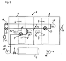
- Fig. 3 shows a scheme of the preferred control of a two-chamber CTI system.
- the cooling system 1 in Fig. 1 comprises a cooling chamber 2, in which at least one Heat exchanger 4 for evaporating refrigerated liquefied gas, at least one Phase separator 20 for separation of cold liquefied gas and gas formed therefrom and at least one heat exchanger 5 for heating off liquefied gas formed gas are arranged.
- One or more fans 6, 7 are advantageous Cooling chamber 2 is arranged.
- a storage tank 8 for refrigerated liquefied gas e.g. cold-liquefied nitrogen (LIN) is introduced via line 21, the liquefied gas in passed the heat exchanger 4 in the cooling chamber 2. There is cold liquefied gas evaporated and the cooling surfaces of the heat exchanger cooled.
- LIN cold-liquefied nitrogen
- From the heat exchanger 4 is formed via a connecting line of refrigerant liquefied gas gas Phase separator 20 fed, separated in the liquefied gas from the gas and is returned to the heat exchanger 4.
- the formed, cold gas becomes in one or several heat exchangers 5 passed through a connecting line, where with the cold gas the heat exchanger is cooled while the gas is heated.
- the gas is passed via a line from the cooling chamber 2 and there for use (e.g., as a purge gas for a separate inert gas chamber or as Compressed gas for driving a device such as a fan 6, 7) supplied or as Exhaust into the free 22 dissipated.
- the device 1 usually has at least one Temperature sensor 14 in the cooling chamber 2 and advantageously a temperature sensor 18th outside the cooling chamber 2 on.
- the temperature sensors 14, 18 are used in the scheme a control or regulation of the cooling device 1.
- the temperature sensors 14, 18 are usually connected to a control unit (not shown) of the cooling device 1.
- Also not shown are advantageously one or more controllable valves, e.g. Solenoid valves, in the conduit 21 and one or more of the following Connecting lines arranged.
- the fans 6, 7 serve to distribute the cold Air in the cooling chamber 2 and can be used to control the cooling capacity of the Heat exchangers 4, 5 are used.
- the control of one or more fans 6, 7 takes place advantageously via a central control in the cooling system 1.
- the multi-chamber system in FIG. 2 is constructed analogously to the cooling system of FIG. 1. Shown is a two-chamber system 1 with the cooling chambers 2 and 3. In each Cooling chamber 2, 3 is at least one heat exchanger 4, 5, at least one fan 6, 7th and at least one temperature sensor 14 is arranged. In the cooling chamber 2, as in Fig. 1 is a heat exchanger evaporator 4, a phase separator 20 and one or more Heat exchanger Gasan Anlagenr 5 may be arranged. The other cooling chambers, Cooling chamber 3 and optionally further cooling chambers contain at least one Heat exchanger Gasanmaschiner 5. The phase separator 20 may also in the following Cooling chamber, cooling chamber 3, the heat exchanger 5 upstream, be arranged. Also in Fig. 2 are possible controllable valves and an advantageous control unit is not shown.
- the multi-chamber system, as well as the single-chamber system is preferred in a refrigerated vehicle (e.g., truck with one or more refrigerated chambers).
- the preferred cooling system 1 for a refrigerated vehicle (two-chamber refrigerated vehicle) is shown schematically in Fig. 3.
- the cooling system includes a freezing chamber 2 for Freezing temperature (e.g., minus 18 ° C) and a fresh service chamber 3 for refrigeration or above 0 ° C (e.g., 7 ° C) in the chamber.
- a storage tank 8 for refrigerated liquefied gas e.g. Refrigerated liquefied nitrogen (LIN)
- LIN refrigerated liquefied gas
- LIN refrigerated liquefied nitrogen
- the heat exchanger 4 (evaporator) is connecting lines via a phase separator (not shown) a further heat exchanger 5 (Gasan Anlagenr) in the second cooling chamber. 3 (Fresh service chamber) and preferably to an exhaust outlet 22.
- Den Heat exchangers 4, 5 are associated with fans 6, 6 ', 6 ", 7, 7' Fig. 3, the preferably controllable valves 9, 10 and 11 are shown.
- Further valves can be arranged, for example, the cooling capacity of the Heat exchanger 4, 5 to control.
- In the cooling chambers 2, 3 are temperature sensors 14, 15, 16, 17 arranged. Outside the cooling chambers is at least one temperature sensor 18th arranged to measure the outside temperature. The temperature sensors are used in the Rule for controlling the cooling in the cooling chambers 2, 3.
- the cooling chambers 2, 3 usually have a door 12 or 13 on.
- the system may include other sensors, e.g. a pressure sensor 19, have.
- the system 1 includes a control unit, preferably a central control unit.
- the system recognizes the need to cool down from the present Temperatures. Depending on the cooling demand is via the valves 10 and 11 of the gas path certainly. Due to the presumed conditions, the refrigeration demand is in the first Chamber 2 always the largest. It is therefore preferably cooled in this phase.
- the outside temperature indicates the cooling demand. From this the permissible ones derive Phase Separator (20) and exhaust temperatures from. From the target / actual comparisons result in the fan performance.
- the fans 6, 6 ', 6 ", 7, 7 'of the respective chambers 2, 3 controlled only proportionally so-called PID characteristic is conceivable, but makes for vehicles with many door openings 12, 13 no sense, because the predictive properties of the scheme constantly be misled.
- the fans 6, 6 ', 6 "or 7, 7' are only switched off completely, if the door 12 or 13 is opened. In cooling mode, it can only on a smallest Performance can be reduced, as this is for a representative temperature measurement necessary is.
- the second chamber of the cooling be separated. When the temperature in the first chamber reaches the cooling completely switched off.
- each heat exchanger 4, 5 After a selectable time or number of door openings since switching on or after the signal of an ice probe, a defrost cycle of each heat exchanger 4, 5 begins.
- the heat exchanger 5 In the second chamber 3 (temperature greater than zero), the heat exchanger 5 can only be warmed up by the fans 7, 7 'to the extent that the ice build-up melts off. This is not possible in the first chamber 2 (temperature below freezing point).
- another mechanism can be used.
- heat exchanger evaporators 4 for liquid nitrogen do not immediately form ice, but produce a very dry powder snow. This can be blown off by pressure pulses (eg gas shocks).
Applications Claiming Priority (2)
| Application Number | Priority Date | Filing Date | Title |
|---|---|---|---|
| DE102004022867 | 2004-05-06 | ||
| DE102004022867 | 2004-05-06 |
Publications (3)
| Publication Number | Publication Date |
|---|---|
| EP1593918A2 true EP1593918A2 (fr) | 2005-11-09 |
| EP1593918A3 EP1593918A3 (fr) | 2008-12-03 |
| EP1593918B1 EP1593918B1 (fr) | 2013-03-13 |
Family
ID=34939677
Family Applications (1)
| Application Number | Title | Priority Date | Filing Date |
|---|---|---|---|
| EP20050103711 Active EP1593918B1 (fr) | 2004-05-06 | 2005-05-03 | Refroidissement indirect pour des véhicules frigorifiques |
Country Status (1)
| Country | Link |
|---|---|
| EP (1) | EP1593918B1 (fr) |
Cited By (13)
| Publication number | Priority date | Publication date | Assignee | Title |
|---|---|---|---|---|
| DE102006016557A1 (de) * | 2006-04-07 | 2007-10-11 | Air Liquide Deutschland Gmbh | Kühlfahrzeug mit externem Kühlmodul und Kühlverfahren |
| DE102006016559A1 (de) * | 2006-04-07 | 2007-10-11 | Air Liquide Deutschland Gmbh | Wärmetauscher für ein mobiles Kühlfahrzeug |
| DE102006016555A1 (de) * | 2006-04-07 | 2007-10-11 | Air Liquide Deutschland Gmbh | Verfahren und Vorrichtung zum Aufbauen eines Überdrucks in einem Tank für verflüssigtes Gas eines Kühlfahrzeugs sowie Kühlsystem für ein Kühlfahrzeug und Kühlfahrzeug |
| WO2008116723A1 (fr) * | 2007-03-28 | 2008-10-02 | L'air Liquide Societe Anonyme Pour L'etude Et L'exploitation Des Procedes Georges Claude | Procédé et dispositif de réfrigération d'un entrepôt frigorifique et véhicule de réfrigération associé |
| DE102007015388A1 (de) * | 2007-03-28 | 2008-10-02 | Air Liquide Deutschland Gmbh | Kühlraum, insbesondere bei einem Kühlfahrzeug |
| WO2010128233A1 (fr) * | 2009-05-07 | 2010-11-11 | L'air Liquide Societe Anonyme Pour L'etude Et L'exploitation Des Procedes Georges Claude | Procédé et dispositif pour le transport réfrigéré utilisant une injection indirecte d'un liquide cryogénique et maîtrisant les phénomènes de givrage des échangeurs |
| ES2352991A1 (es) * | 2008-12-31 | 2011-02-21 | Criogenius S L | Dispositivo para refrigerar un cuerpo y procedimiento para enfriar un cuerpo u objeto. |
| WO2011151548A1 (fr) * | 2010-06-03 | 2011-12-08 | L'Air Liquide, Société Anonyme pour l'Etude et l'Exploitation des Procédés Georges Claude | Procede et installation de refroidissement cryogenique utilisant du co2 liquide et mettant en oeuvre deux echangeurs en serie |
| WO2013004946A1 (fr) * | 2011-07-07 | 2013-01-10 | L'air Liquide,Societe Anonyme Pour L'etude Et L'exploitation Des Procedes Georges Claude | Procede et dispositif pour le transport refrigere utilisant une injection indirecte d'un liquide cryogenique et ameliorant la distribution du cryogene dans les echangeurs thermiques |
| EP2565567A1 (fr) | 2011-08-30 | 2013-03-06 | Air Liquide Deutschland GmbH | Procédé et dispositif de refroidissement et de production d'une atmosphère similaire à l'air et véhicule de refroidissement |
| WO2013050800A1 (fr) * | 2011-10-03 | 2013-04-11 | Renault Trucks | Camion avec un compartiment réfrigéré |
| US20140157804A1 (en) * | 2012-12-11 | 2014-06-12 | Michael D. Newman | Transit refrigeration control apparatus and method |
| EP3147600A1 (fr) * | 2015-09-25 | 2017-03-29 | Linde Aktiengesellschaft | Appareil de réfrigération |
Citations (5)
| Publication number | Priority date | Publication date | Assignee | Title |
|---|---|---|---|---|
| US3685310A (en) | 1970-09-25 | 1972-08-22 | Allied Chem | Open cycle ammonia refrigeration system including a catalytic ammonia burner |
| US5267443A (en) | 1992-11-27 | 1993-12-07 | Thermo King Corporation | Air conditioning and refrigeration methods and apparatus utilizing a cryogen |
| EP0599610A2 (fr) | 1992-11-27 | 1994-06-01 | Thermo King Corporation | Procédé et appareil de conditionnement de l'air et de réfrigération sous utilisation d'un cryogène |
| US5582015A (en) | 1994-12-27 | 1996-12-10 | Ecometrics Corp. | Liquid nitrogen capillary heat exchanger |
| EP0826937B1 (fr) | 1996-08-29 | 2003-07-16 | Messer Griesheim GmbH | Unité de réfrigération |
Family Cites Families (3)
| Publication number | Priority date | Publication date | Assignee | Title |
|---|---|---|---|---|
| GB9302928D0 (en) * | 1993-02-13 | 1993-03-31 | Air Prod & Chem | Refrigeration system |
| EP0624763A1 (fr) * | 1993-05-10 | 1994-11-17 | General Electric Company | Evaporateur à décharche libre d'un système frigorifique |
| US6345509B1 (en) * | 2000-01-21 | 2002-02-12 | Ukram Industries | Refrigeration of a food transport vehicle utilizing liquid nitrogen |
-
2005
- 2005-05-03 EP EP20050103711 patent/EP1593918B1/fr active Active
Patent Citations (5)
| Publication number | Priority date | Publication date | Assignee | Title |
|---|---|---|---|---|
| US3685310A (en) | 1970-09-25 | 1972-08-22 | Allied Chem | Open cycle ammonia refrigeration system including a catalytic ammonia burner |
| US5267443A (en) | 1992-11-27 | 1993-12-07 | Thermo King Corporation | Air conditioning and refrigeration methods and apparatus utilizing a cryogen |
| EP0599610A2 (fr) | 1992-11-27 | 1994-06-01 | Thermo King Corporation | Procédé et appareil de conditionnement de l'air et de réfrigération sous utilisation d'un cryogène |
| US5582015A (en) | 1994-12-27 | 1996-12-10 | Ecometrics Corp. | Liquid nitrogen capillary heat exchanger |
| EP0826937B1 (fr) | 1996-08-29 | 2003-07-16 | Messer Griesheim GmbH | Unité de réfrigération |
Cited By (19)
| Publication number | Priority date | Publication date | Assignee | Title |
|---|---|---|---|---|
| DE102006016559A1 (de) * | 2006-04-07 | 2007-10-11 | Air Liquide Deutschland Gmbh | Wärmetauscher für ein mobiles Kühlfahrzeug |
| DE102006016555A1 (de) * | 2006-04-07 | 2007-10-11 | Air Liquide Deutschland Gmbh | Verfahren und Vorrichtung zum Aufbauen eines Überdrucks in einem Tank für verflüssigtes Gas eines Kühlfahrzeugs sowie Kühlsystem für ein Kühlfahrzeug und Kühlfahrzeug |
| WO2007116383A2 (fr) * | 2006-04-07 | 2007-10-18 | L'air Liquide Societe Anonyme Pour L'etude Et L'exploitation Des Procedes Georges Claude | Echangeur de chaleur pour vehicule frigorifie mobile |
| WO2007116383A3 (fr) * | 2006-04-07 | 2007-12-21 | Air Liquide | Echangeur de chaleur pour vehicule frigorifie mobile |
| US9506681B2 (en) | 2006-04-07 | 2016-11-29 | L'Air Liquide Société Anonyme Pour L'Étude Et L'Exploitation Des Procedes Georges Claude | Method and device for generating a positive pressure in a tank for liquefied gas on a refrigerated vehicle and a cooling system for a refrigerated vehicle and a refrigerated vehicle |
| DE102006016557A1 (de) * | 2006-04-07 | 2007-10-11 | Air Liquide Deutschland Gmbh | Kühlfahrzeug mit externem Kühlmodul und Kühlverfahren |
| WO2008116723A1 (fr) * | 2007-03-28 | 2008-10-02 | L'air Liquide Societe Anonyme Pour L'etude Et L'exploitation Des Procedes Georges Claude | Procédé et dispositif de réfrigération d'un entrepôt frigorifique et véhicule de réfrigération associé |
| DE102007015388A1 (de) * | 2007-03-28 | 2008-10-02 | Air Liquide Deutschland Gmbh | Kühlraum, insbesondere bei einem Kühlfahrzeug |
| ES2352991A1 (es) * | 2008-12-31 | 2011-02-21 | Criogenius S L | Dispositivo para refrigerar un cuerpo y procedimiento para enfriar un cuerpo u objeto. |
| FR2945336A1 (fr) * | 2009-05-07 | 2010-11-12 | Air Liquide | Procede et dispositif pour le transport regrigere utilisant une injection indirecte d'un liquide cryogenique et maitrisant les phenomenes de givrage des echangeurs. |
| WO2010128233A1 (fr) * | 2009-05-07 | 2010-11-11 | L'air Liquide Societe Anonyme Pour L'etude Et L'exploitation Des Procedes Georges Claude | Procédé et dispositif pour le transport réfrigéré utilisant une injection indirecte d'un liquide cryogénique et maîtrisant les phénomènes de givrage des échangeurs |
| WO2011151548A1 (fr) * | 2010-06-03 | 2011-12-08 | L'Air Liquide, Société Anonyme pour l'Etude et l'Exploitation des Procédés Georges Claude | Procede et installation de refroidissement cryogenique utilisant du co2 liquide et mettant en oeuvre deux echangeurs en serie |
| FR2960952A1 (fr) * | 2010-06-03 | 2011-12-09 | Air Liquide | Procede et installation de refroidissement cryogenique utilisant du co2 liquide mettant en oeuvre deux echangeurs en serie |
| WO2013004946A1 (fr) * | 2011-07-07 | 2013-01-10 | L'air Liquide,Societe Anonyme Pour L'etude Et L'exploitation Des Procedes Georges Claude | Procede et dispositif pour le transport refrigere utilisant une injection indirecte d'un liquide cryogenique et ameliorant la distribution du cryogene dans les echangeurs thermiques |
| FR2977658A1 (fr) * | 2011-07-07 | 2013-01-11 | Air Liquide | Procede et dispositif pour le transport refrigere utilisant une injection indirecte d’un liquide cryogenique et ameliorant la distribution du cryogene dans les echangeurs thermiques |
| EP2565567A1 (fr) | 2011-08-30 | 2013-03-06 | Air Liquide Deutschland GmbH | Procédé et dispositif de refroidissement et de production d'une atmosphère similaire à l'air et véhicule de refroidissement |
| WO2013050800A1 (fr) * | 2011-10-03 | 2013-04-11 | Renault Trucks | Camion avec un compartiment réfrigéré |
| US20140157804A1 (en) * | 2012-12-11 | 2014-06-12 | Michael D. Newman | Transit refrigeration control apparatus and method |
| EP3147600A1 (fr) * | 2015-09-25 | 2017-03-29 | Linde Aktiengesellschaft | Appareil de réfrigération |
Also Published As
| Publication number | Publication date |
|---|---|
| EP1593918B1 (fr) | 2013-03-13 |
| EP1593918A3 (fr) | 2008-12-03 |
Similar Documents
| Publication | Publication Date | Title |
|---|---|---|
| EP1593918B1 (fr) | Refroidissement indirect pour des véhicules frigorifiques | |
| DE10229865B4 (de) | Tiefsttemperatur-Steuervorrichtung und -Verfahren | |
| EP2590878B1 (fr) | Installation frigorifique pour refroidir un conteneur | |
| EP2342511B1 (fr) | Réfrigérateur domestique, ainsi que système modulaire de réfrigérateur domestique | |
| DE102006048993B4 (de) | Verfahren zum Betreiben einer Tieftemperatursteuereinrichtung | |
| EP3014197B1 (fr) | Système de réfrigération de transport à compartiments multiples ayant une vanne d'isolement d'évaporateur | |
| DE102004018292A1 (de) | Umweltfreundliches Verfahren und Vorrichtung zum Kühlen eines Raums mit geregelter Temperatur | |
| DE10217975A1 (de) | Verfahren zum Entdecken von Änderungen in einem ersten Medienstrom eines Wärme- oder Kältetransportmediums in einer Kälteanlage | |
| EP2951512B1 (fr) | Système frigorifique de transport à compartiments multiples ayant un économiseur | |
| DE10229864A1 (de) | Tiefsttemperatur-Steuervorrichtung und -Verfahren | |
| DE102011014746A1 (de) | Vorrichtung und Verfahren zum Betrieb eines Kühlsystems mit zwei oder mehr Kühlkammern | |
| DE102013005476A1 (de) | Kühl- und/oder Gefriergerät | |
| DE102017110560B4 (de) | Kältemittelkreislauf einer Kälteanlage mit einer Anordnung zum Abtauen eines Wärmeübertragers und Verfahren zum Betreiben des Kältemittelkreislaufs | |
| DE102006046931A1 (de) | Indirekt arbeitendes Kühlsystem für ein Kühlfahrzeug | |
| DE102007015390A1 (de) | Verfahren und Vorrichtung zum Kühlen eines Kühlraums sowie Kühlfahrzeug | |
| EP0783658B1 (fr) | Procede et dispositif de refroidissement de gaz | |
| EP0602379B1 (fr) | Réfrigérateur, en particulier réfrigérateur à plusieurs températures | |
| EP1350068B1 (fr) | Procede pour reguler un appareil de refroidissement | |
| DE1906044U (de) | Kraftfahrzeug mit geschlossenem kastenaufbau und kuehlaggregat. | |
| DE10300703B4 (de) | Gefriergerät und Enteisungsverfahren | |
| DE60029851T2 (de) | Fahrzeug mit mehreren gekühlten Laderäumen | |
| DE4105880A1 (de) | Verfahren und vorrichtung zur leistungsoptimierung und abtausteuerung von kaeltemittelverdampfern | |
| DE102017205426A1 (de) | Kältegerät und Betriebsverfahren dafür | |
| DE102016223050A1 (de) | Kühlkreislauf für ein Fahrzeug, insbesondere zur Kühlung eines Kühlgutraums eines Transportfahrzeugs | |
| WO2021259630A1 (fr) | Dispositif de refroidissement doté d'un échangeur de chaleur à tube d'aspiration et procédé d'actionnement d'un dispositif de refroidissement doté d'un échangeur de chaleur à tube d'aspiration |
Legal Events
| Date | Code | Title | Description |
|---|---|---|---|
| PUAI | Public reference made under article 153(3) epc to a published international application that has entered the european phase |
Free format text: ORIGINAL CODE: 0009012 |
|
| AK | Designated contracting states |
Kind code of ref document: A2 Designated state(s): AT BE BG CH CY CZ DE DK EE ES FI FR GB GR HU IE IS IT LI LT LU MC NL PL PT RO SE SI SK TR |
|
| AX | Request for extension of the european patent |
Extension state: AL BA HR LV MK YU |
|
| RAP1 | Party data changed (applicant data changed or rights of an application transferred) |
Owner name: MESSER GROUP GMBH Owner name: AIR LIQUIDE DEUTSCHLAND GMBH Owner name: L'AIR LIQUIDE, SOCIETE ANONYME POUR L'ETUDE ET L'E |
|
| RAP1 | Party data changed (applicant data changed or rights of an application transferred) |
Owner name: MESSER GROUP GMBH Owner name: AIR LIQUIDE DEUTSCHLAND GMBH Owner name: L'AIR LIQUIDE, SOCIETE ANONYME POUR L'ETUDE ET L'E |
|
| PUAL | Search report despatched |
Free format text: ORIGINAL CODE: 0009013 |
|
| AK | Designated contracting states |
Kind code of ref document: A3 Designated state(s): AT BE BG CH CY CZ DE DK EE ES FI FR GB GR HU IE IS IT LI LT LU MC NL PL PT RO SE SI SK TR |
|
| AX | Request for extension of the european patent |
Extension state: AL BA HR LV MK YU |
|
| 17P | Request for examination filed |
Effective date: 20090428 |
|
| RAP1 | Party data changed (applicant data changed or rights of an application transferred) |
Owner name: L'AIR LIQUIDE, SOCIETE ANONYME POUR L'ETUDE ET L'E Owner name: AIR LIQUIDE DEUTSCHLAND GMBH |
|
| 17Q | First examination report despatched |
Effective date: 20120207 |
|
| GRAP | Despatch of communication of intention to grant a patent |
Free format text: ORIGINAL CODE: EPIDOSNIGR1 |
|
| GRAS | Grant fee paid |
Free format text: ORIGINAL CODE: EPIDOSNIGR3 |
|
| GRAA | (expected) grant |
Free format text: ORIGINAL CODE: 0009210 |
|
| AK | Designated contracting states |
Kind code of ref document: B1 Designated state(s): AT BE BG CH CY CZ DE DK EE ES FI FR GB GR HU IE IS IT LI LT LU MC NL PL PT RO SE SI SK TR |
|
| REG | Reference to a national code |
Ref country code: GB Ref legal event code: FG4D Free format text: NOT ENGLISH |
|
| REG | Reference to a national code |
Ref country code: CH Ref legal event code: EP Ref country code: AT Ref legal event code: REF Ref document number: 601036 Country of ref document: AT Kind code of ref document: T Effective date: 20130315 |
|
| REG | Reference to a national code |
Ref country code: IE Ref legal event code: FG4D Free format text: LANGUAGE OF EP DOCUMENT: GERMAN |
|
| REG | Reference to a national code |
Ref country code: DE Ref legal event code: R096 Ref document number: 502005013539 Country of ref document: DE Effective date: 20130508 |
|
| REG | Reference to a national code |
Ref country code: DE Ref legal event code: R082 Ref document number: 502005013539 Country of ref document: DE Representative=s name: KNH PATENTANWAELTE KAHLHOEFER NEUMANN ROESSLER, DE Ref country code: DE Ref legal event code: R082 Ref document number: 502005013539 Country of ref document: DE Representative=s name: KNH PATENTANWAELTE NEUMANN HEINE TARUTTIS PART, DE |
|
| PG25 | Lapsed in a contracting state [announced via postgrant information from national office to epo] |
Ref country code: BG Free format text: LAPSE BECAUSE OF FAILURE TO SUBMIT A TRANSLATION OF THE DESCRIPTION OR TO PAY THE FEE WITHIN THE PRESCRIBED TIME-LIMIT Effective date: 20130613 Ref country code: SE Free format text: LAPSE BECAUSE OF FAILURE TO SUBMIT A TRANSLATION OF THE DESCRIPTION OR TO PAY THE FEE WITHIN THE PRESCRIBED TIME-LIMIT Effective date: 20130313 Ref country code: LT Free format text: LAPSE BECAUSE OF FAILURE TO SUBMIT A TRANSLATION OF THE DESCRIPTION OR TO PAY THE FEE WITHIN THE PRESCRIBED TIME-LIMIT Effective date: 20130313 Ref country code: ES Free format text: LAPSE BECAUSE OF FAILURE TO SUBMIT A TRANSLATION OF THE DESCRIPTION OR TO PAY THE FEE WITHIN THE PRESCRIBED TIME-LIMIT Effective date: 20130624 |
|
| REG | Reference to a national code |
Ref country code: NL Ref legal event code: VDEP Effective date: 20130313 |
|
| REG | Reference to a national code |
Ref country code: LT Ref legal event code: MG4D |
|
| PG25 | Lapsed in a contracting state [announced via postgrant information from national office to epo] |
Ref country code: FI Free format text: LAPSE BECAUSE OF FAILURE TO SUBMIT A TRANSLATION OF THE DESCRIPTION OR TO PAY THE FEE WITHIN THE PRESCRIBED TIME-LIMIT Effective date: 20130313 Ref country code: GR Free format text: LAPSE BECAUSE OF FAILURE TO SUBMIT A TRANSLATION OF THE DESCRIPTION OR TO PAY THE FEE WITHIN THE PRESCRIBED TIME-LIMIT Effective date: 20130614 Ref country code: SI Free format text: LAPSE BECAUSE OF FAILURE TO SUBMIT A TRANSLATION OF THE DESCRIPTION OR TO PAY THE FEE WITHIN THE PRESCRIBED TIME-LIMIT Effective date: 20130313 |
|
| PG25 | Lapsed in a contracting state [announced via postgrant information from national office to epo] |
Ref country code: CZ Free format text: LAPSE BECAUSE OF FAILURE TO SUBMIT A TRANSLATION OF THE DESCRIPTION OR TO PAY THE FEE WITHIN THE PRESCRIBED TIME-LIMIT Effective date: 20130313 Ref country code: NL Free format text: LAPSE BECAUSE OF FAILURE TO SUBMIT A TRANSLATION OF THE DESCRIPTION OR TO PAY THE FEE WITHIN THE PRESCRIBED TIME-LIMIT Effective date: 20130313 Ref country code: RO Free format text: LAPSE BECAUSE OF FAILURE TO SUBMIT A TRANSLATION OF THE DESCRIPTION OR TO PAY THE FEE WITHIN THE PRESCRIBED TIME-LIMIT Effective date: 20130313 Ref country code: IS Free format text: LAPSE BECAUSE OF FAILURE TO SUBMIT A TRANSLATION OF THE DESCRIPTION OR TO PAY THE FEE WITHIN THE PRESCRIBED TIME-LIMIT Effective date: 20130713 Ref country code: PT Free format text: LAPSE BECAUSE OF FAILURE TO SUBMIT A TRANSLATION OF THE DESCRIPTION OR TO PAY THE FEE WITHIN THE PRESCRIBED TIME-LIMIT Effective date: 20130715 Ref country code: EE Free format text: LAPSE BECAUSE OF FAILURE TO SUBMIT A TRANSLATION OF THE DESCRIPTION OR TO PAY THE FEE WITHIN THE PRESCRIBED TIME-LIMIT Effective date: 20130313 Ref country code: SK Free format text: LAPSE BECAUSE OF FAILURE TO SUBMIT A TRANSLATION OF THE DESCRIPTION OR TO PAY THE FEE WITHIN THE PRESCRIBED TIME-LIMIT Effective date: 20130313 |
|
| PG25 | Lapsed in a contracting state [announced via postgrant information from national office to epo] |
Ref country code: CY Free format text: LAPSE BECAUSE OF FAILURE TO SUBMIT A TRANSLATION OF THE DESCRIPTION OR TO PAY THE FEE WITHIN THE PRESCRIBED TIME-LIMIT Effective date: 20130313 Ref country code: PL Free format text: LAPSE BECAUSE OF FAILURE TO SUBMIT A TRANSLATION OF THE DESCRIPTION OR TO PAY THE FEE WITHIN THE PRESCRIBED TIME-LIMIT Effective date: 20130313 |
|
| BERE | Be: lapsed |
Owner name: AIR LIQUIDE DEUTSCHLAND G.M.B.H. Effective date: 20130531 Owner name: L'AIR LIQUIDE, S.A. POUR L'ETUDE ET L'EXPLOITATIO Effective date: 20130531 |
|
| PG25 | Lapsed in a contracting state [announced via postgrant information from national office to epo] |
Ref country code: MC Free format text: LAPSE BECAUSE OF FAILURE TO SUBMIT A TRANSLATION OF THE DESCRIPTION OR TO PAY THE FEE WITHIN THE PRESCRIBED TIME-LIMIT Effective date: 20130313 |
|
| REG | Reference to a national code |
Ref country code: CH Ref legal event code: PL |
|
| PLBE | No opposition filed within time limit |
Free format text: ORIGINAL CODE: 0009261 |
|
| STAA | Information on the status of an ep patent application or granted ep patent |
Free format text: STATUS: NO OPPOSITION FILED WITHIN TIME LIMIT |
|
| PG25 | Lapsed in a contracting state [announced via postgrant information from national office to epo] |
Ref country code: CH Free format text: LAPSE BECAUSE OF NON-PAYMENT OF DUE FEES Effective date: 20130531 Ref country code: DK Free format text: LAPSE BECAUSE OF FAILURE TO SUBMIT A TRANSLATION OF THE DESCRIPTION OR TO PAY THE FEE WITHIN THE PRESCRIBED TIME-LIMIT Effective date: 20130313 Ref country code: LI Free format text: LAPSE BECAUSE OF NON-PAYMENT OF DUE FEES Effective date: 20130531 |
|
| 26N | No opposition filed |
Effective date: 20131216 |
|
| REG | Reference to a national code |
Ref country code: IE Ref legal event code: MM4A |
|
| PG25 | Lapsed in a contracting state [announced via postgrant information from national office to epo] |
Ref country code: BE Free format text: LAPSE BECAUSE OF NON-PAYMENT OF DUE FEES Effective date: 20130531 Ref country code: IT Free format text: LAPSE BECAUSE OF FAILURE TO SUBMIT A TRANSLATION OF THE DESCRIPTION OR TO PAY THE FEE WITHIN THE PRESCRIBED TIME-LIMIT Effective date: 20130313 |
|
| REG | Reference to a national code |
Ref country code: DE Ref legal event code: R097 Ref document number: 502005013539 Country of ref document: DE Effective date: 20131216 |
|
| PG25 | Lapsed in a contracting state [announced via postgrant information from national office to epo] |
Ref country code: IE Free format text: LAPSE BECAUSE OF NON-PAYMENT OF DUE FEES Effective date: 20130503 |
|
| REG | Reference to a national code |
Ref country code: AT Ref legal event code: MM01 Ref document number: 601036 Country of ref document: AT Kind code of ref document: T Effective date: 20130503 |
|
| PG25 | Lapsed in a contracting state [announced via postgrant information from national office to epo] |
Ref country code: AT Free format text: LAPSE BECAUSE OF NON-PAYMENT OF DUE FEES Effective date: 20130503 |
|
| PG25 | Lapsed in a contracting state [announced via postgrant information from national office to epo] |
Ref country code: TR Free format text: LAPSE BECAUSE OF FAILURE TO SUBMIT A TRANSLATION OF THE DESCRIPTION OR TO PAY THE FEE WITHIN THE PRESCRIBED TIME-LIMIT Effective date: 20130313 |
|
| PG25 | Lapsed in a contracting state [announced via postgrant information from national office to epo] |
Ref country code: HU Free format text: LAPSE BECAUSE OF FAILURE TO SUBMIT A TRANSLATION OF THE DESCRIPTION OR TO PAY THE FEE WITHIN THE PRESCRIBED TIME-LIMIT; INVALID AB INITIO Effective date: 20050503 Ref country code: LU Free format text: LAPSE BECAUSE OF NON-PAYMENT OF DUE FEES Effective date: 20130503 |
|
| REG | Reference to a national code |
Ref country code: FR Ref legal event code: PLFP Year of fee payment: 12 |
|
| REG | Reference to a national code |
Ref country code: FR Ref legal event code: PLFP Year of fee payment: 13 |
|
| REG | Reference to a national code |
Ref country code: FR Ref legal event code: PLFP Year of fee payment: 14 |
|
| PGFP | Annual fee paid to national office [announced via postgrant information from national office to epo] |
Ref country code: FR Payment date: 20230525 Year of fee payment: 19 Ref country code: DE Payment date: 20230519 Year of fee payment: 19 |
|
| PGFP | Annual fee paid to national office [announced via postgrant information from national office to epo] |
Ref country code: GB Payment date: 20230522 Year of fee payment: 19 |