EP1593892A2 - Emmeteur de signaux - Google Patents
Emmeteur de signaux Download PDFInfo
- Publication number
- EP1593892A2 EP1593892A2 EP05008463A EP05008463A EP1593892A2 EP 1593892 A2 EP1593892 A2 EP 1593892A2 EP 05008463 A EP05008463 A EP 05008463A EP 05008463 A EP05008463 A EP 05008463A EP 1593892 A2 EP1593892 A2 EP 1593892A2
- Authority
- EP
- European Patent Office
- Prior art keywords
- actuating
- actuator
- torque
- switching shaft
- shaft
- Prior art date
- Legal status (The legal status is an assumption and is not a legal conclusion. Google has not performed a legal analysis and makes no representation as to the accuracy of the status listed.)
- Granted
Links
- 238000000034 method Methods 0.000 claims abstract description 13
- 230000004913 activation Effects 0.000 claims description 11
- 230000011664 signaling Effects 0.000 claims description 7
- 230000006835 compression Effects 0.000 claims description 5
- 238000007906 compression Methods 0.000 claims description 5
- 239000000523 sample Substances 0.000 claims description 5
- 230000001066 destructive effect Effects 0.000 claims 2
- 238000009434 installation Methods 0.000 description 4
- 230000001939 inductive effect Effects 0.000 description 2
- 206010003830 Automatism Diseases 0.000 description 1
- 239000013590 bulk material Substances 0.000 description 1
- 239000004020 conductor Substances 0.000 description 1
- 230000008878 coupling Effects 0.000 description 1
- 238000010168 coupling process Methods 0.000 description 1
- 238000005859 coupling reaction Methods 0.000 description 1
- 238000005516 engineering process Methods 0.000 description 1
- 230000036316 preload Effects 0.000 description 1
- 239000000126 substance Substances 0.000 description 1
- 230000001360 synchronised effect Effects 0.000 description 1
- 230000001960 triggered effect Effects 0.000 description 1
Images


Classifications
-
- F—MECHANICAL ENGINEERING; LIGHTING; HEATING; WEAPONS; BLASTING
- F16—ENGINEERING ELEMENTS AND UNITS; GENERAL MEASURES FOR PRODUCING AND MAINTAINING EFFECTIVE FUNCTIONING OF MACHINES OR INSTALLATIONS; THERMAL INSULATION IN GENERAL
- F16K—VALVES; TAPS; COCKS; ACTUATING-FLOATS; DEVICES FOR VENTING OR AERATING
- F16K37/00—Special means in or on valves or other cut-off apparatus for indicating or recording operation thereof, or for enabling an alarm to be given
- F16K37/0025—Electrical or magnetic means
- F16K37/0041—Electrical or magnetic means for measuring valve parameters
Definitions
- the invention relates to a method for setting a signal generator for a Actuator, as well as a signal generator, each according to the features of the preamble of Claims 1 and 2, respectively.
- Signalers are required to transmit electrical signals via mechanical conditions in particular fittings such as e.g. Ball valves, flap valves and the like and their To give actuators.
- a typical application is the information via the end position for valves with adjustable and thus variable switching states.
- To perform the pivotal movement of the valve is a drive shaft of the Semi-rotary drive with the valve rotatably connected and the rotational movement of the valve is synchronous with the rotational movement of the drive shaft.
- transducers used with a shift shaft engage in the drive shaft and have with her a common axis of rotation.
- signalers are, for example, from US Pat. No. 5,305,781 or EP 0 921 338 B 1 known, the latter font an internal or external toothing for Switch cam and shift shaft provides that intermesh and in the manner of a Locking coupling can be adjusted elastically.
- a disadvantage of manual settings of the signal generator is the associated Workload, the possibility of adjustment errors and the associated risk that the switching point of a switch was set inaccurate and this no longer in an end position switches.
- the object of the invention is to provide a method for setting a signal generator for a Actuator and the signal generator itself specify in which a manual adjustment and Manual readjustment can be omitted.
- the object is achieved in that a method is specified by which a Operating body connected in any position with the switching shaft and the Actuator is moved to the set end position, the actuator body before Reaching the end position against a fixedly connected to the housing stop element strikes and then with continued rotation of the shift shaft on this slips until the actuator has reached the end position and is thus set.
- the task is solved by each switch associated stop element against which the actuating body in the or shortly behind the position abuts in which the switch is actuated, wherein the stop element so trained and so firmly connected to the housing that of him when striking the actuator body resulting from the torque limit force nondestructive is receivable.
- the method according to the invention can completely on a setting by hand with the are to be accepted in buying tolerances, since the signal generator by sets the first pivoting movement by itself. This will be a very big Saving of working time i. Costs achieved.
- the achieved switching tolerance so the Angle between the position at the switching time and the actual end position, is by this automatism much more accurate, than with the well-known attitude of Hand.
- Another advantage is that the switching tolerance for an entire series of a Signal generator according to the invention is always consistent with procedures, so that errors in the switching system more likely to be limited and thus calculable, since human error, which always occur due to misalignment of the signal generator can be excluded from the outset.
- Another immediate advantage of the method is the automatic adjustment of the method according to the invention during operation, since by the Process steps according to the invention at each enlargement of the pivot angle to Compensation of valve wear, as in practice almost exclusively occur immediately after the actuator has changed its setting changed self-adjustment of the signal generator takes place.
- the design of the switch can of course be varied, for. B. is also a above-described inductive switch by resorting to a corresponding Actuator possible.
- the switch can also by the way Actuator and the stop element itself may be formed, in this case, e.g. As an electrical conductor would be formed, wherein the switching operation at a contact of the two components would be triggered together.
- the mechanical Switch design probably the most cost-effective variant currently and should therefore be a be preferred embodiment of the signal generator.
- the actuating body by means of a Spring element in the axial direction of the switching shaft on an end face thereof can be prestressed.
- a development of the invention should be that the shift shaft a shoulder and a to this subsequent diameter-reduced mounting portion for has the at least one actuating body, in the region of a receiving bore with game of the attachment portion is penetrable, and that the spring element is a compression spring, by means of a tensioning element, on the mounting portion is displaceable, can be pressed against the shoulder of the shift shaft, because it ensures is that the actuator body can rotate freely radially, but in the axial direction receives a defined position.
- the invention is further developed in that the attachment portion with a section is provided with an external thread on which one as a clamping element serving clamping nut can be screwed.
- a rotationally fixed with the Switching shaft connected friction ring is arranged, since such a friction ring by his Surface structure even with a slight pressure on the actuators ensures a sufficient frictional engagement, so that a used clamping element, such as a clamping nut to be clamped with a correspondingly little effort can.
- a development of the invention is that two actuator body starting from a mounting position in which they make an angle between their Include stop surfaces smaller than that between the stop elements included angle is, by temporarily lowering the limit torque on a Activation moment by means of a torsion spring whose spring moment is greater than that Activation moment is to be converted into an activation position in which the Actuator abut on the respective associated stop element, wherein the Spring moment is less than the limit torque.
- the torsion spring to a Shifter shaft is wound spiral spring, with end portions in openings in the cam or finger-shaped actuating body engages.
- the invention should be configured by the fact that the limit torque can be lowered onto the activation element by means of a spring-loaded probe element, wherein the probe element automatically returns to the home position, in the with the Slip clutch the limit torque is transferable.
- FIGS. 1 to 5 show a signal generator 1 according to the invention with two Actuators 2, 3.
- the two actuating body 2, 3 are on a switching shaft. 4 fastened by means of a clamping nut 5.
- the enclosing housing is because of the larger ones Clarity not shown and also not how the shift shaft 4 with her lower portion 4 'is rotatably passed through the housing and thereby on a drive shaft of an actuator also not shown here rotatably coupled is.
- the lower actuating body 2 is located directly on a shoulder 5 'of the switching shaft 4 in Shape of a radially encircling edge of the lower portion 4 'of the switching shaft 4.
- Friction ring 6 With the actuator body 2 is a friction ring 6, with a nose 7 in a Groove 8 of the shift shaft 4 engages and thereby rotatably connected thereto.
- Friction ring 6 Above that Friction ring 6 is the second actuator body 3, which of a spring element 9 in Shape of a compression spring is pressed down.
- the clamping nut 5 acts as a Stop surface of the spring element 9 and is on the mounting portion 10 in the form an external thread tensioned.
- Torsion spring 11 Between the two actuating bodies 3, 4 and the Friction ring 6 outside enclosing, there is another spring element in the form of a tortuous spiral spring, i. Torsion spring 11.
- Torsion spring 11 engages with their end pieces 12, 13 in each case an opening 14, 15 of the actuating body 2, 3 and exercises due to their Preload a certain torque on the two actuator body 2, 3 from.
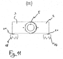
- Fig. 11 an activation position 22 is shown, in which the clamping nut. 5 compared to the position in Fig. 1 to 5 solved so far that the compression spring and the Operating body 2, 3 are free of tension in the axial direction.
- the torsion spring 11 presses the both actuating body 2, 3, since there is no frictional engagement, against the push buttons 21, 21 'of the switches 17, 18, so that the two switches 17, 18 connected in this state are.
Landscapes
- Engineering & Computer Science (AREA)
- General Engineering & Computer Science (AREA)
- Mechanical Engineering (AREA)
- Gear-Shifting Mechanisms (AREA)
- Stereo-Broadcasting Methods (AREA)
- Reduction Or Emphasis Of Bandwidth Of Signals (AREA)
- Radar Systems Or Details Thereof (AREA)
- Hydraulic Clutches, Magnetic Clutches, Fluid Clutches, And Fluid Joints (AREA)
- Arrangements For Transmission Of Measured Signals (AREA)
- Mechanical Control Devices (AREA)
- Control Of Position Or Direction (AREA)
- Steering Controls (AREA)
Applications Claiming Priority (2)
| Application Number | Priority Date | Filing Date | Title |
|---|---|---|---|
| DE102004021631 | 2004-05-03 | ||
| DE102004021631A DE102004021631A1 (de) | 2004-05-03 | 2004-05-03 | Signalgeber |
Publications (3)
| Publication Number | Publication Date |
|---|---|
| EP1593892A2 true EP1593892A2 (fr) | 2005-11-09 |
| EP1593892A3 EP1593892A3 (fr) | 2006-01-25 |
| EP1593892B1 EP1593892B1 (fr) | 2008-07-16 |
Family
ID=34935346
Family Applications (1)
| Application Number | Title | Priority Date | Filing Date |
|---|---|---|---|
| EP05008463A Active EP1593892B1 (fr) | 2004-05-03 | 2005-04-19 | Emmeteur de signaux |
Country Status (4)
| Country | Link |
|---|---|
| EP (1) | EP1593892B1 (fr) |
| AT (1) | ATE401523T1 (fr) |
| DE (2) | DE102004021631A1 (fr) |
| DK (1) | DK1593892T3 (fr) |
Cited By (1)
| Publication number | Priority date | Publication date | Assignee | Title |
|---|---|---|---|---|
| CN112503241A (zh) * | 2020-11-30 | 2021-03-16 | 贵州电网有限责任公司 | 一种新型sf6设备三通阀状态显示装置 |
Citations (2)
| Publication number | Priority date | Publication date | Assignee | Title |
|---|---|---|---|---|
| US5305781A (en) | 1992-03-20 | 1994-04-26 | Bray International, Inc. | Valve positioning monitoring apparatus |
| EP0921338A1 (fr) | 1997-12-06 | 1999-06-09 | Armatic Gesellschaft für automatische Armaturen mbH | Dispositif de signalisation pour un actionneur |
Family Cites Families (3)
| Publication number | Priority date | Publication date | Assignee | Title |
|---|---|---|---|---|
| HU174770B (hu) * | 1977-05-18 | 1980-03-28 | Koolaj Gazipari Tervezo | Prisposoblenie dlja izmerenija povorota povorotnykh chastej dvizhuhhikhsja ili privodnykh mekhanizmov a tak zhe dlja poluchenija informacionnykh i/ili vozdejstvujuhhikh signalov |
| EP1062448B1 (fr) * | 1998-03-16 | 2004-05-26 | Foxboro Eckardt GmbH | Reglage d'un emetteur de signaux |
| ITTO20010508A1 (it) * | 2001-05-28 | 2002-11-28 | Rizzio Valvole S P A | Trasduttore ottico per il rilevamento e l'indicazione a distanza di posizioni predetermitate di un organo mobile, particolarmente di un orga |
-
2004
- 2004-05-03 DE DE102004021631A patent/DE102004021631A1/de not_active Ceased
-
2005
- 2005-04-19 DK DK05008463T patent/DK1593892T3/da active
- 2005-04-19 AT AT05008463T patent/ATE401523T1/de not_active IP Right Cessation
- 2005-04-19 DE DE502005004694T patent/DE502005004694D1/de active Active
- 2005-04-19 EP EP05008463A patent/EP1593892B1/fr active Active
Patent Citations (2)
| Publication number | Priority date | Publication date | Assignee | Title |
|---|---|---|---|---|
| US5305781A (en) | 1992-03-20 | 1994-04-26 | Bray International, Inc. | Valve positioning monitoring apparatus |
| EP0921338A1 (fr) | 1997-12-06 | 1999-06-09 | Armatic Gesellschaft für automatische Armaturen mbH | Dispositif de signalisation pour un actionneur |
Cited By (2)
| Publication number | Priority date | Publication date | Assignee | Title |
|---|---|---|---|---|
| CN112503241A (zh) * | 2020-11-30 | 2021-03-16 | 贵州电网有限责任公司 | 一种新型sf6设备三通阀状态显示装置 |
| CN112503241B (zh) * | 2020-11-30 | 2022-12-13 | 贵州电网有限责任公司 | 一种新型sf6设备三通阀状态显示装置 |
Also Published As
| Publication number | Publication date |
|---|---|
| ATE401523T1 (de) | 2008-08-15 |
| DE502005004694D1 (de) | 2008-08-28 |
| EP1593892B1 (fr) | 2008-07-16 |
| DK1593892T3 (da) | 2008-10-06 |
| DE102004021631A1 (de) | 2005-12-01 |
| EP1593892A3 (fr) | 2006-01-25 |
Similar Documents
| Publication | Publication Date | Title |
|---|---|---|
| DE102006007600B4 (de) | Drehsteller für elektrische oder elektronische Gräte in einem Kraftfahrzeug | |
| EP3446003B1 (fr) | Actionneur et dispositif pour actionner un frein de stationnement d'une boîte de vitesses automatique de véhicule automobile à l'aide d'un actionneur de ce type ainsi que véhicule automobile équipé de ce dispositif | |
| DE102010018243B4 (de) | Schließzylinderanordnung | |
| DE102017108626B4 (de) | Drehmomentsteckhülse | |
| DE3934952C2 (fr) | ||
| DE10313440A1 (de) | Vorrichtung zum automatischen Verschwenken einer auch manuell betätigbaren Fahrzeugtür | |
| DE60013294T2 (de) | Elektrischer schalter für einen gashahn | |
| DE2633218C3 (de) | Antriebsmechanismus für die Kontaktbewegung in einem Leistungsschalter | |
| EP0462449B1 (fr) | Dispositif de positionnement d'arbre de commande pour boîtes de vitesses | |
| CH626810A5 (fr) | ||
| EP1593892B1 (fr) | Emmeteur de signaux | |
| DE69628673T2 (de) | Betätigungseinrichtung für eine elektrische schaltvorrichtung | |
| EP2557335B1 (fr) | Dispositif de transmission de force pour un engrenage | |
| WO2019179557A1 (fr) | Dispositif de fermeture pour une trappe de réservoir | |
| DE19754271C1 (de) | Signalgeber für einen Stellantrieb | |
| WO2022152498A1 (fr) | Mécanisme de blocage de stationnement pour véhicule motorisé | |
| DE60200390T2 (de) | Schaltwerk | |
| DE4415134A1 (de) | Nockenanordnung zur Benutzung in Drehstellungs-Anzeigegeräten | |
| EP1619414A2 (fr) | Actionneur | |
| EP0836959B1 (fr) | Dispositif d'émergence pour l'actionnement d'un toit coulissant | |
| DE19918652C2 (de) | Drehbare Anschlußeinheit für eine elektrische Baueinheit | |
| EP1057960B1 (fr) | Dispositif de manoeuvre | |
| DE10240552A1 (de) | Kraftfahrzeug Türschloß | |
| DE102014005628A1 (de) | Armaturen-Schaltvorrichtung und Armaturen-Stellanordnung | |
| EP2712996A2 (fr) | Dispositif de mouvement pour un élément mobile de meuble |
Legal Events
| Date | Code | Title | Description |
|---|---|---|---|
| PUAI | Public reference made under article 153(3) epc to a published international application that has entered the european phase |
Free format text: ORIGINAL CODE: 0009012 |
|
| AK | Designated contracting states |
Kind code of ref document: A2 Designated state(s): AT BE BG CH CY CZ DE DK EE ES FI FR GB GR HU IE IS IT LI LT LU MC NL PL PT RO SE SI SK TR |
|
| AX | Request for extension of the european patent |
Extension state: AL BA HR LV MK YU |
|
| PUAL | Search report despatched |
Free format text: ORIGINAL CODE: 0009013 |
|
| AK | Designated contracting states |
Kind code of ref document: A3 Designated state(s): AT BE BG CH CY CZ DE DK EE ES FI FR GB GR HU IE IS IT LI LT LU MC NL PL PT RO SE SI SK TR |
|
| AX | Request for extension of the european patent |
Extension state: AL BA HR LV MK YU |
|
| 17P | Request for examination filed |
Effective date: 20060719 |
|
| AKX | Designation fees paid |
Designated state(s): AT BE BG CH CY CZ DE DK EE ES FI FR GB GR HU IE IS IT LI LT LU MC NL PL PT RO SE SI SK TR |
|
| GRAP | Despatch of communication of intention to grant a patent |
Free format text: ORIGINAL CODE: EPIDOSNIGR1 |
|
| GRAS | Grant fee paid |
Free format text: ORIGINAL CODE: EPIDOSNIGR3 |
|
| GRAA | (expected) grant |
Free format text: ORIGINAL CODE: 0009210 |
|
| AK | Designated contracting states |
Kind code of ref document: B1 Designated state(s): AT BE BG CH CY CZ DE DK EE ES FI FR GB GR HU IE IS IT LI LT LU MC NL PL PT RO SE SI SK TR |
|
| REG | Reference to a national code |
Ref country code: GB Ref legal event code: FG4D Free format text: NOT ENGLISH |
|
| REG | Reference to a national code |
Ref country code: CH Ref legal event code: EP |
|
| REF | Corresponds to: |
Ref document number: 502005004694 Country of ref document: DE Date of ref document: 20080828 Kind code of ref document: P |
|
| REG | Reference to a national code |
Ref country code: CH Ref legal event code: NV Representative=s name: PA ALDO ROEMPLER |
|
| REG | Reference to a national code |
Ref country code: IE Ref legal event code: FG4D Free format text: LANGUAGE OF EP DOCUMENT: GERMAN |
|
| REG | Reference to a national code |
Ref country code: CH Ref legal event code: PCAR Free format text: ALDO ROEMPLER PATENTANWALT;BRENDENWEG 11 POSTFACH 154;9424 RHEINECK (CH) |
|
| PG25 | Lapsed in a contracting state [announced via postgrant information from national office to epo] |
Ref country code: IS Free format text: LAPSE BECAUSE OF FAILURE TO SUBMIT A TRANSLATION OF THE DESCRIPTION OR TO PAY THE FEE WITHIN THE PRESCRIBED TIME-LIMIT Effective date: 20081116 Ref country code: LT Free format text: LAPSE BECAUSE OF FAILURE TO SUBMIT A TRANSLATION OF THE DESCRIPTION OR TO PAY THE FEE WITHIN THE PRESCRIBED TIME-LIMIT Effective date: 20080716 Ref country code: PT Free format text: LAPSE BECAUSE OF FAILURE TO SUBMIT A TRANSLATION OF THE DESCRIPTION OR TO PAY THE FEE WITHIN THE PRESCRIBED TIME-LIMIT Effective date: 20081216 Ref country code: ES Free format text: LAPSE BECAUSE OF FAILURE TO SUBMIT A TRANSLATION OF THE DESCRIPTION OR TO PAY THE FEE WITHIN THE PRESCRIBED TIME-LIMIT Effective date: 20081027 |
|
| PG25 | Lapsed in a contracting state [announced via postgrant information from national office to epo] |
Ref country code: FI Free format text: LAPSE BECAUSE OF FAILURE TO SUBMIT A TRANSLATION OF THE DESCRIPTION OR TO PAY THE FEE WITHIN THE PRESCRIBED TIME-LIMIT Effective date: 20080716 Ref country code: BG Free format text: LAPSE BECAUSE OF FAILURE TO SUBMIT A TRANSLATION OF THE DESCRIPTION OR TO PAY THE FEE WITHIN THE PRESCRIBED TIME-LIMIT Effective date: 20081016 Ref country code: SI Free format text: LAPSE BECAUSE OF FAILURE TO SUBMIT A TRANSLATION OF THE DESCRIPTION OR TO PAY THE FEE WITHIN THE PRESCRIBED TIME-LIMIT Effective date: 20080716 |
|
| REG | Reference to a national code |
Ref country code: IE Ref legal event code: FD4D |
|
| PG25 | Lapsed in a contracting state [announced via postgrant information from national office to epo] |
Ref country code: EE Free format text: LAPSE BECAUSE OF FAILURE TO SUBMIT A TRANSLATION OF THE DESCRIPTION OR TO PAY THE FEE WITHIN THE PRESCRIBED TIME-LIMIT Effective date: 20080716 Ref country code: IE Free format text: LAPSE BECAUSE OF FAILURE TO SUBMIT A TRANSLATION OF THE DESCRIPTION OR TO PAY THE FEE WITHIN THE PRESCRIBED TIME-LIMIT Effective date: 20080716 |
|
| PLBE | No opposition filed within time limit |
Free format text: ORIGINAL CODE: 0009261 |
|
| STAA | Information on the status of an ep patent application or granted ep patent |
Free format text: STATUS: NO OPPOSITION FILED WITHIN TIME LIMIT |
|
| PG25 | Lapsed in a contracting state [announced via postgrant information from national office to epo] |
Ref country code: RO Free format text: LAPSE BECAUSE OF FAILURE TO SUBMIT A TRANSLATION OF THE DESCRIPTION OR TO PAY THE FEE WITHIN THE PRESCRIBED TIME-LIMIT Effective date: 20080716 Ref country code: SK Free format text: LAPSE BECAUSE OF FAILURE TO SUBMIT A TRANSLATION OF THE DESCRIPTION OR TO PAY THE FEE WITHIN THE PRESCRIBED TIME-LIMIT Effective date: 20080716 Ref country code: CZ Free format text: LAPSE BECAUSE OF FAILURE TO SUBMIT A TRANSLATION OF THE DESCRIPTION OR TO PAY THE FEE WITHIN THE PRESCRIBED TIME-LIMIT Effective date: 20080716 |
|
| 26N | No opposition filed |
Effective date: 20090417 |
|
| BERE | Be: lapsed |
Owner name: BAR-PNEUMATISCHE STEUERUNGSSYSTEME G.M.B.H. Effective date: 20090430 |
|
| REG | Reference to a national code |
Ref country code: CH Ref legal event code: PL |
|
| REG | Reference to a national code |
Ref country code: DK Ref legal event code: EBP |
|
| GBPC | Gb: european patent ceased through non-payment of renewal fee |
Effective date: 20090419 |
|
| NLV4 | Nl: lapsed or anulled due to non-payment of the annual fee |
Effective date: 20091101 |
|
| REG | Reference to a national code |
Ref country code: FR Ref legal event code: ST Effective date: 20091231 |
|
| PG25 | Lapsed in a contracting state [announced via postgrant information from national office to epo] |
Ref country code: CH Free format text: LAPSE BECAUSE OF NON-PAYMENT OF DUE FEES Effective date: 20090430 Ref country code: LI Free format text: LAPSE BECAUSE OF NON-PAYMENT OF DUE FEES Effective date: 20090430 Ref country code: SE Free format text: LAPSE BECAUSE OF FAILURE TO SUBMIT A TRANSLATION OF THE DESCRIPTION OR TO PAY THE FEE WITHIN THE PRESCRIBED TIME-LIMIT Effective date: 20081016 |
|
| PG25 | Lapsed in a contracting state [announced via postgrant information from national office to epo] |
Ref country code: NL Free format text: LAPSE BECAUSE OF NON-PAYMENT OF DUE FEES Effective date: 20091101 |
|
| PG25 | Lapsed in a contracting state [announced via postgrant information from national office to epo] |
Ref country code: MC Free format text: LAPSE BECAUSE OF NON-PAYMENT OF DUE FEES Effective date: 20090430 Ref country code: DK Free format text: LAPSE BECAUSE OF NON-PAYMENT OF DUE FEES Effective date: 20090430 Ref country code: FR Free format text: LAPSE BECAUSE OF NON-PAYMENT OF DUE FEES Effective date: 20091222 Ref country code: GB Free format text: LAPSE BECAUSE OF NON-PAYMENT OF DUE FEES Effective date: 20090419 |
|
| PG25 | Lapsed in a contracting state [announced via postgrant information from national office to epo] |
Ref country code: BE Free format text: LAPSE BECAUSE OF NON-PAYMENT OF DUE FEES Effective date: 20090430 Ref country code: PL Free format text: LAPSE BECAUSE OF FAILURE TO SUBMIT A TRANSLATION OF THE DESCRIPTION OR TO PAY THE FEE WITHIN THE PRESCRIBED TIME-LIMIT Effective date: 20080716 |
|
| PG25 | Lapsed in a contracting state [announced via postgrant information from national office to epo] |
Ref country code: AT Free format text: LAPSE BECAUSE OF NON-PAYMENT OF DUE FEES Effective date: 20090419 |
|
| PG25 | Lapsed in a contracting state [announced via postgrant information from national office to epo] |
Ref country code: IT Free format text: LAPSE BECAUSE OF NON-PAYMENT OF DUE FEES Effective date: 20090419 |
|
| PG25 | Lapsed in a contracting state [announced via postgrant information from national office to epo] |
Ref country code: LU Free format text: LAPSE BECAUSE OF NON-PAYMENT OF DUE FEES Effective date: 20090419 |
|
| PG25 | Lapsed in a contracting state [announced via postgrant information from national office to epo] |
Ref country code: HU Free format text: LAPSE BECAUSE OF FAILURE TO SUBMIT A TRANSLATION OF THE DESCRIPTION OR TO PAY THE FEE WITHIN THE PRESCRIBED TIME-LIMIT Effective date: 20090117 |
|
| PG25 | Lapsed in a contracting state [announced via postgrant information from national office to epo] |
Ref country code: TR Free format text: LAPSE BECAUSE OF FAILURE TO SUBMIT A TRANSLATION OF THE DESCRIPTION OR TO PAY THE FEE WITHIN THE PRESCRIBED TIME-LIMIT Effective date: 20080716 |
|
| PG25 | Lapsed in a contracting state [announced via postgrant information from national office to epo] |
Ref country code: CY Free format text: LAPSE BECAUSE OF FAILURE TO SUBMIT A TRANSLATION OF THE DESCRIPTION OR TO PAY THE FEE WITHIN THE PRESCRIBED TIME-LIMIT Effective date: 20080716 |
|
| PG25 | Lapsed in a contracting state [announced via postgrant information from national office to epo] |
Ref country code: GR Free format text: LAPSE BECAUSE OF FAILURE TO SUBMIT A TRANSLATION OF THE DESCRIPTION OR TO PAY THE FEE WITHIN THE PRESCRIBED TIME-LIMIT Effective date: 20080716 |
|
| REG | Reference to a national code |
Ref country code: DE Ref legal event code: R082 Ref document number: 502005004694 Country of ref document: DE Representative=s name: BAUER WAGNER PELLENGAHR SROKA PATENT- & RECHTS, DE |
|
| P01 | Opt-out of the competence of the unified patent court (upc) registered |
Effective date: 20230527 |
|
| PGFP | Annual fee paid to national office [announced via postgrant information from national office to epo] |
Ref country code: DE Payment date: 20240923 Year of fee payment: 20 |