EP1593892A2 - Signal transmitter - Google Patents
Signal transmitter Download PDFInfo
- Publication number
- EP1593892A2 EP1593892A2 EP05008463A EP05008463A EP1593892A2 EP 1593892 A2 EP1593892 A2 EP 1593892A2 EP 05008463 A EP05008463 A EP 05008463A EP 05008463 A EP05008463 A EP 05008463A EP 1593892 A2 EP1593892 A2 EP 1593892A2
- Authority
- EP
- European Patent Office
- Prior art keywords
- actuating
- actuator
- torque
- switching shaft
- shaft
- Prior art date
- Legal status (The legal status is an assumption and is not a legal conclusion. Google has not performed a legal analysis and makes no representation as to the accuracy of the status listed.)
- Granted
Links
Images


Classifications
-
- F—MECHANICAL ENGINEERING; LIGHTING; HEATING; WEAPONS; BLASTING
- F16—ENGINEERING ELEMENTS AND UNITS; GENERAL MEASURES FOR PRODUCING AND MAINTAINING EFFECTIVE FUNCTIONING OF MACHINES OR INSTALLATIONS; THERMAL INSULATION IN GENERAL
- F16K—VALVES; TAPS; COCKS; ACTUATING-FLOATS; DEVICES FOR VENTING OR AERATING
- F16K37/00—Special means in or on valves or other cut-off apparatus for indicating or recording operation thereof, or for enabling an alarm to be given
- F16K37/0025—Electrical or magnetic means
- F16K37/0041—Electrical or magnetic means for measuring valve parameters
Definitions
- the invention relates to a method for setting a signal generator for a Actuator, as well as a signal generator, each according to the features of the preamble of Claims 1 and 2, respectively.
- Signalers are required to transmit electrical signals via mechanical conditions in particular fittings such as e.g. Ball valves, flap valves and the like and their To give actuators.
- a typical application is the information via the end position for valves with adjustable and thus variable switching states.
- To perform the pivotal movement of the valve is a drive shaft of the Semi-rotary drive with the valve rotatably connected and the rotational movement of the valve is synchronous with the rotational movement of the drive shaft.
- transducers used with a shift shaft engage in the drive shaft and have with her a common axis of rotation.
- signalers are, for example, from US Pat. No. 5,305,781 or EP 0 921 338 B 1 known, the latter font an internal or external toothing for Switch cam and shift shaft provides that intermesh and in the manner of a Locking coupling can be adjusted elastically.
- a disadvantage of manual settings of the signal generator is the associated Workload, the possibility of adjustment errors and the associated risk that the switching point of a switch was set inaccurate and this no longer in an end position switches.
- the object of the invention is to provide a method for setting a signal generator for a Actuator and the signal generator itself specify in which a manual adjustment and Manual readjustment can be omitted.
- the object is achieved in that a method is specified by which a Operating body connected in any position with the switching shaft and the Actuator is moved to the set end position, the actuator body before Reaching the end position against a fixedly connected to the housing stop element strikes and then with continued rotation of the shift shaft on this slips until the actuator has reached the end position and is thus set.
- the task is solved by each switch associated stop element against which the actuating body in the or shortly behind the position abuts in which the switch is actuated, wherein the stop element so trained and so firmly connected to the housing that of him when striking the actuator body resulting from the torque limit force nondestructive is receivable.
- the method according to the invention can completely on a setting by hand with the are to be accepted in buying tolerances, since the signal generator by sets the first pivoting movement by itself. This will be a very big Saving of working time i. Costs achieved.
- the achieved switching tolerance so the Angle between the position at the switching time and the actual end position, is by this automatism much more accurate, than with the well-known attitude of Hand.
- Another advantage is that the switching tolerance for an entire series of a Signal generator according to the invention is always consistent with procedures, so that errors in the switching system more likely to be limited and thus calculable, since human error, which always occur due to misalignment of the signal generator can be excluded from the outset.
- Another immediate advantage of the method is the automatic adjustment of the method according to the invention during operation, since by the Process steps according to the invention at each enlargement of the pivot angle to Compensation of valve wear, as in practice almost exclusively occur immediately after the actuator has changed its setting changed self-adjustment of the signal generator takes place.
- the design of the switch can of course be varied, for. B. is also a above-described inductive switch by resorting to a corresponding Actuator possible.
- the switch can also by the way Actuator and the stop element itself may be formed, in this case, e.g. As an electrical conductor would be formed, wherein the switching operation at a contact of the two components would be triggered together.
- the mechanical Switch design probably the most cost-effective variant currently and should therefore be a be preferred embodiment of the signal generator.
- the actuating body by means of a Spring element in the axial direction of the switching shaft on an end face thereof can be prestressed.
- a development of the invention should be that the shift shaft a shoulder and a to this subsequent diameter-reduced mounting portion for has the at least one actuating body, in the region of a receiving bore with game of the attachment portion is penetrable, and that the spring element is a compression spring, by means of a tensioning element, on the mounting portion is displaceable, can be pressed against the shoulder of the shift shaft, because it ensures is that the actuator body can rotate freely radially, but in the axial direction receives a defined position.
- the invention is further developed in that the attachment portion with a section is provided with an external thread on which one as a clamping element serving clamping nut can be screwed.
- a rotationally fixed with the Switching shaft connected friction ring is arranged, since such a friction ring by his Surface structure even with a slight pressure on the actuators ensures a sufficient frictional engagement, so that a used clamping element, such as a clamping nut to be clamped with a correspondingly little effort can.
- a development of the invention is that two actuator body starting from a mounting position in which they make an angle between their Include stop surfaces smaller than that between the stop elements included angle is, by temporarily lowering the limit torque on a Activation moment by means of a torsion spring whose spring moment is greater than that Activation moment is to be converted into an activation position in which the Actuator abut on the respective associated stop element, wherein the Spring moment is less than the limit torque.
- the torsion spring to a Shifter shaft is wound spiral spring, with end portions in openings in the cam or finger-shaped actuating body engages.
- the invention should be configured by the fact that the limit torque can be lowered onto the activation element by means of a spring-loaded probe element, wherein the probe element automatically returns to the home position, in the with the Slip clutch the limit torque is transferable.
- FIGS. 1 to 5 show a signal generator 1 according to the invention with two Actuators 2, 3.
- the two actuating body 2, 3 are on a switching shaft. 4 fastened by means of a clamping nut 5.
- the enclosing housing is because of the larger ones Clarity not shown and also not how the shift shaft 4 with her lower portion 4 'is rotatably passed through the housing and thereby on a drive shaft of an actuator also not shown here rotatably coupled is.
- the lower actuating body 2 is located directly on a shoulder 5 'of the switching shaft 4 in Shape of a radially encircling edge of the lower portion 4 'of the switching shaft 4.
- Friction ring 6 With the actuator body 2 is a friction ring 6, with a nose 7 in a Groove 8 of the shift shaft 4 engages and thereby rotatably connected thereto.
- Friction ring 6 Above that Friction ring 6 is the second actuator body 3, which of a spring element 9 in Shape of a compression spring is pressed down.
- the clamping nut 5 acts as a Stop surface of the spring element 9 and is on the mounting portion 10 in the form an external thread tensioned.
- Torsion spring 11 Between the two actuating bodies 3, 4 and the Friction ring 6 outside enclosing, there is another spring element in the form of a tortuous spiral spring, i. Torsion spring 11.
- Torsion spring 11 engages with their end pieces 12, 13 in each case an opening 14, 15 of the actuating body 2, 3 and exercises due to their Preload a certain torque on the two actuator body 2, 3 from.
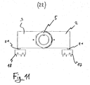
- Fig. 11 an activation position 22 is shown, in which the clamping nut. 5 compared to the position in Fig. 1 to 5 solved so far that the compression spring and the Operating body 2, 3 are free of tension in the axial direction.
- the torsion spring 11 presses the both actuating body 2, 3, since there is no frictional engagement, against the push buttons 21, 21 'of the switches 17, 18, so that the two switches 17, 18 connected in this state are.
Abstract
Description
Die Erfindung betrifft ein Verfahren zur Einstellung eines Signalgebers für einen
Stellantrieb, sowie einen Signalgeber, jeweils gemäß den Merkmalen des Oberbegriffs der
Ansprüche 1 bzw. 2.The invention relates to a method for setting a signal generator for a
Actuator, as well as a signal generator, each according to the features of the preamble of
Signalgeber werden benötigt, um elektrische Signale über mechanische Zustände insbesondere von Armaturen, wie z.B. Kugelhähnen, Klappenventilen u.ä. und deren Stellantrieben zu geben. Einen typischen Anwendungsfall bildet dabei die Information über die Endlage bei Armaturen mit einstellbaren und damit variablen Schaltzuständen. Zur Ausführung der Schwenkbewegung der Armatur ist eine Antriebswelle des Schwenkantriebs mit der Armatur drehfest verbunden und die Drehbewegung der Armatur ist synchron zu der Drehbewegung der Antriebswelle. Zur Information über eine Endstellung der Armatur muss also lediglich die Drehbewegung der Antriebswelle des Stellantriebs erfasst werden. Bekanntermaßen werden dazu spezielle Signalgebereinrichtungen, kurz Signalgeber genannt, verwendet, die mit einer Schaltwelle in die Antriebswelle eingreifen und mit ihr eine gemeinsame Drehachse besitzen. Für die Rückmeldung über eine Endlage, also ob die Armatur geöffnet oder geschlossen ist, müssen bei einem bekannten Signalgeber Nocken so an der Schaltwelle befestigt und justiert werden, dass die jeweilige Endlage und der Schaltpunkt eines Schalters, gegen den die jeweilige Nocke bei Einnahme der Endlage anschlägt, exakt übereinstimmt. Signalgeber mit Schaltnocken und davon mechanisch betätigbaren Endschaltern sind dabei die übliche Variante zur Realisierung eines Schaltvorgangs, jedoch sind auch kontaktlose, d.h. induktive Verfahren bekannt.Signalers are required to transmit electrical signals via mechanical conditions in particular fittings such as e.g. Ball valves, flap valves and the like and their To give actuators. A typical application is the information via the end position for valves with adjustable and thus variable switching states. To perform the pivotal movement of the valve is a drive shaft of the Semi-rotary drive with the valve rotatably connected and the rotational movement of the valve is synchronous with the rotational movement of the drive shaft. For information about one Endstellung of the valve so only the rotational movement of the drive shaft of the Actuator are detected. As is known, special Signaling devices, called transducers for short, used with a shift shaft engage in the drive shaft and have with her a common axis of rotation. For the Feedback on an end position, ie whether the valve is open or closed, must be attached to a known signal generator cam on the shift shaft and be adjusted that the respective end position and the switching point of a switch, against the the respective cam strikes when taking the end position, exactly matches. Signalers with switching cams and mechanically operated limit switches are included the usual variant for realizing a switching operation, but are also contactless, i.e. inductive method known.
Beispiele von Signalgebern sind zum Beispiel aus der US-A-5 305 781 oder der EP 0 921 338 B 1 bekannt, wobei die letztgenannte Schrift eine Innen bzw. Außenverzahnung für Schaltnocken und Schaltwelle vorsieht, die ineinander eingreifen und nach Art einer Rastkupplung elastisch justiert werden kann.Examples of signalers are, for example, from US Pat. No. 5,305,781 or EP 0 921 338 B 1 known, the latter font an internal or external toothing for Switch cam and shift shaft provides that intermesh and in the manner of a Locking coupling can be adjusted elastically.
Allen bekannten Signalgebern ist gemeinsam, dass sie beim Einbau von Hand justiert werden müssen. Da Armaturen und deren Dichtungen während ihrer Lebensdauer einem Verschleiß unterliegen, müssen sie von Zeit zu Zeit nachgestellt werden. Dabei ist ebenfalls der Signalgeber nachzustellen, d. h. die Schaltnocken auf der Schaltwelle zu verschieben. All known signal transmitters have in common that they adjusted during installation by hand Need to become. Since fittings and their seals during their life one Wear, they must be adjusted from time to time. It is also adjust the signal generator, d. H. the switching cam on the shift shaft too move.
Nachteilig bei Handeinstellungen der Signalgeber ist der damit verbundene Arbeitsaufwand, die Möglichkeit von Einstellfehlern und das damit verbundene Risiko, dass der Schaltpunkt eines Schalters ungenau eingestellt wurde und dieser nicht mehr in einer Endlage schaltet.A disadvantage of manual settings of the signal generator is the associated Workload, the possibility of adjustment errors and the associated risk that the switching point of a switch was set inaccurate and this no longer in an end position switches.
Zu einer echten Gefahr kann sich ein solches Risiko im übrigen dann entwickeln, wenn besonders sensible Anlagen wie Chemiefabriken oder Atomreaktoren mit derartigen Armaturen bzw. deren Signalgebern ausgestattet sind.Moreover, such a risk can become a real danger if particularly sensitive installations such as chemical plants or nuclear reactors with such Fittings or their signal generators are equipped.
Aufgabe der Erfindung ist es, ein Verfahren zur Einstellung eines Signalgebers für einen Stellantrieb sowie den Signalgeber selbst anzugeben, bei dem eine Handeinstellung und händige Nachjustierung entfallen kann.The object of the invention is to provide a method for setting a signal generator for a Actuator and the signal generator itself specify in which a manual adjustment and Manual readjustment can be omitted.
Die Aufgabe wird dadurch gelöst, dass ein Verfahren angegeben wird, durch welches ein Betätigungskörper in einer beliebigen Stellung mit der Schaltwelle verbunden und der Stellantrieb in die eingestellte Endlage gefahren wird, wobei der Betätigungskörper vor Erreichen der Endlage gegen ein fest mit dem Gehäuse verbundenes Anschlagelement anschlägt und anschließend bei fortgesetzter Drehbewegung der Schaltwelle auf dieser solange durchrutscht, bis der Stellantrieb die Endlage erreicht hat und damit eingestellt ist. In Bezug auf den Signalgeber ist die Aufgabe gelöst durch ein jedem Schalter zugeordnetes Anschlagelement, gegen das der Betätigungskörper in der oder kurz hinter der Stellung anschlägt, in der der Schalter betätigt wird, wobei das Anschlagelement so ausgebildet und so fest mit dem Gehäuse verbunden ist, dass von ihm beim Anschlagen des Betätigungskörpers die sich aus dem Grenzmoment ergebende Kraft zerstörungsfrei aufnehmbar ist.The object is achieved in that a method is specified by which a Operating body connected in any position with the switching shaft and the Actuator is moved to the set end position, the actuator body before Reaching the end position against a fixedly connected to the housing stop element strikes and then with continued rotation of the shift shaft on this slips until the actuator has reached the end position and is thus set. With respect to the signal transmitter, the task is solved by each switch associated stop element against which the actuating body in the or shortly behind the position abuts in which the switch is actuated, wherein the stop element so trained and so firmly connected to the housing that of him when striking the actuator body resulting from the torque limit force nondestructive is receivable.
Durch das erfindungsgemäße Verfahren kann völlig auf eine Einstellung von Hand mit den dabei in Kauf zu nehmenden Toleranzen verzichtet werden, da sich der Signalgeber durch die erste Schwenkbewegung von selbst einstellt. Hierdurch wird eine sehr große Einsparung an Arbeitszeit d.h. Kosten erzielt. Die dabei erzielte Schalt-Toleranz, also der Winkel zwischen der Stellung zum Schaltzeitpunkt und der tatsächlichen Endlage, ist durch diesen Automatismus sehr viel genauer, als die bei der bekannten Einstellung von Hand. Ein weiterer Vorteil ist, dass die Schalt-Toleranz für eine gesamte Baureihe eines erfindungsgemäßen Signalgebers nebst Verfahren stets gleichbleibend ist, so dass Fehler im Schaltsystem wahrscheinlicher einzugrenzen und damit kalkulierbarer sind, da menschliches Versagen, welches durch Fehljustierung der Signalgeber stets vorkommen kann, von vorneherein ausgeschlossen wird.By the method according to the invention can completely on a setting by hand with the are to be accepted in buying tolerances, since the signal generator by sets the first pivoting movement by itself. This will be a very big Saving of working time i. Costs achieved. The achieved switching tolerance, so the Angle between the position at the switching time and the actual end position, is by this automatism much more accurate, than with the well-known attitude of Hand. Another advantage is that the switching tolerance for an entire series of a Signal generator according to the invention is always consistent with procedures, so that errors in the switching system more likely to be limited and thus calculable, since human error, which always occur due to misalignment of the signal generator can be excluded from the outset.
Ein weiterer unmittelbarer Vorteil des Verfahrens ist die selbsttätige Einstellung des erfindungsgemäßen Verfahrens während des laufenden Betriebs, da durch die erfindungsgemäßen Verfahrensschritte bei jeder Vergrößerung des Schwenkwinkels zur Kompensation des Armaturverschleißes, wie sie in der Praxis fast ausschließlich vorkommen, sofort nach der veränderten Einstellung des Stellantriebs, die entsprechend veränderte Selbsteinstellung des Signalgebers erfolgt.Another immediate advantage of the method is the automatic adjustment of the method according to the invention during operation, since by the Process steps according to the invention at each enlargement of the pivot angle to Compensation of valve wear, as in practice almost exclusively occur immediately after the actuator has changed its setting changed self-adjustment of the signal generator takes place.
Die Ausbildung des Schalters kann selbstverständlich variiert werden, z. B. ist auch ein oben beschriebener induktiver Schalter durch einen Rückgriff auf ein entsprechendes Betätigungselement möglich. Der Schalter kann im übrigen auch durch das Betätigungselement und das Anschlagelement selbst gebildet sein, die in diesem Fall z.B. als elektrischer Leiter ausgebildet wären, wobei der Schaltvorgang bei einem Kontakt der beiden Bauteile miteinander ausgelöst werden würde. Allerdings stellt die mechanische Schalterausführung wohl die zur Zeit kostengünstigste Variante dar und soll deshalb eine bevorzugte Ausführungsform des Signalgebers sein.The design of the switch can of course be varied, for. B. is also a above-described inductive switch by resorting to a corresponding Actuator possible. The switch can also by the way Actuator and the stop element itself may be formed, in this case, e.g. As an electrical conductor would be formed, wherein the switching operation at a contact of the two components would be triggered together. However, the mechanical Switch design probably the most cost-effective variant currently and should therefore be a be preferred embodiment of the signal generator.
Besonders bevorzugt soll außerdem sein, dass der Betätigungskörper mittels eines Federelements in axialer Richtung der Schaltwelle auf eine Stirnfläche derselben vorspannbar ist.It should also be particularly preferred that the actuating body by means of a Spring element in the axial direction of the switching shaft on an end face thereof can be prestressed.
Durch die Vorspannung wird die Montage eines Betätigungskörpers innerhalb des Signalgebergehäuses vereinfacht und das Betätigungselement durch den Federdruck des Federelementes mit hinreichendem Reibschluss mit der Schaltwelle gekoppelt.Due to the bias, the assembly of an actuator body within the Auto switch housing simplified and the actuator by the spring pressure of the Spring element coupled with sufficient frictional engagement with the shift shaft.
Eine erfindungsgemäße Weiterbildung soll sein, dass die Schaltwelle eine Schulter und einen sich an diese anschließenden im Durchmesser reduzierten Befestigungsabschnitt für den mindestens einen Betätigungskörper aufweist, der im Bereich einer Aufnahmebohrung mit Spiel von dem Befestigungsabschnitt durchdringbar ist, und dass das Federelement eine Druckfeder ist, die mittels eines Spannelements, das auf dem Befestigungsabschnitt verlagerbar ist, gegen die Schulter der Schaltwelle pressbar ist, weil dadurch gewährleistet wird, dass der Betätigungskörper sich radial frei drehen kann, jedoch in axialer Richtung eine definierte Position erhält.A development of the invention should be that the shift shaft a shoulder and a to this subsequent diameter-reduced mounting portion for has the at least one actuating body, in the region of a receiving bore with game of the attachment portion is penetrable, and that the spring element is a compression spring, by means of a tensioning element, on the mounting portion is displaceable, can be pressed against the shoulder of the shift shaft, because it ensures is that the actuator body can rotate freely radially, but in the axial direction receives a defined position.
Ebenfalls weitergebildet wird die Erfindung dadurch, dass der Befestigungsabschnitt mit einem Abschnitt mit einem Außengewinde versehen ist, auf dem eine als Spannelement dienende Spannmutter aufschraubbar ist.Also, the invention is further developed in that the attachment portion with a section is provided with an external thread on which one as a clamping element serving clamping nut can be screwed.
Durch die vergleichsweise einfache Spanntechnik der Mutter, die zudem ein überall erhältliches Massengut sein kann, wird gewährleistet, dass ein Einbau des erfindungsgemäßen Signalgebers auch mit Standardwerkzeug durchführbar ist.Due to the comparatively simple clamping technology of the mother, which is also an everywhere be available bulk material, it is ensured that an installation of the Signaling device according to the invention can also be carried out with standard tools.
Weiterhin wird bevorzugt, dass zwischen zwei Betätigungskörpern, die axial beabstandet auf dem Befestigungsabschnitt der Schaltwelle angeordnet sind, ein drehfest mit der Schaltwelle verbundener Reibring angeordnet ist, da ein solcher Reibring durch seine Oberflächenstruktur schon bei einem leichten Andruck auf den Betätigungselementen einen ausreichenden Reibschluss gewährleistet, so dass ein verwendetes Spanneelement, wie etwa eine Spannmutter, mit entsprechend wenigem Kraftaufwand gespannt werden kann.Furthermore, it is preferred that between two actuating bodies, axially spaced are arranged on the mounting portion of the shift shaft, a rotationally fixed with the Switching shaft connected friction ring is arranged, since such a friction ring by his Surface structure even with a slight pressure on the actuators ensures a sufficient frictional engagement, so that a used clamping element, such as a clamping nut to be clamped with a correspondingly little effort can.
Weiterhin soll eine Weiterbildung der Erfindung sein, dass zwei Betätigungskörper ausgehend von einer Montagestellung, in der sie einen Winkel zwischen ihren Anschlagflächen einschließen, der kleiner als der zwischen den Anschlagelementen eingeschlossene Winkel ist, durch temporäres Absenken des Grenzmoments auf ein Aktivierungsmoment mittels einer Drehfeder, deren Federmoment größer als das Aktivierungsmoment ist, in eine Aktivierungsstellung überführbar sind, in der die Betätigungskörper an dem jeweils zugeordneten Anschlagelement anschlagen, wobei das Federmoment kleiner als das Grenzmoment ist.Furthermore, a development of the invention is that two actuator body starting from a mounting position in which they make an angle between their Include stop surfaces smaller than that between the stop elements included angle is, by temporarily lowering the limit torque on a Activation moment by means of a torsion spring whose spring moment is greater than that Activation moment is to be converted into an activation position in which the Actuator abut on the respective associated stop element, wherein the Spring moment is less than the limit torque.
Durch einen derartigen Aufbau des Signalgebers lässt sich dieser vereinfacht aktivieren. Durch geeignete Wahl der jeweiligen Momente kann dadurch sogar völlig auf Werkzeug verzichtet werden. Die Drehfeder sorgt dafür, dass beide Betätigungskörper bei Beginn des Einstellvorgangs automatisch an den Anschlagelementen anliegen.By such a structure of the signal generator can be activated this simplified. By suitable choice of the respective moments can thereby even completely on tool be waived. The torsion spring ensures that both actuator bodies at the beginning of the Adjustment automatically abut the stop elements.
Weiterhin soll eine erfindungsgemäße Weiterbildung sein, dass die Drehfeder eine um die Schaltwelle gewundene Biegefeder ist, die mit Endabschnitten in Öffnungen in den nocken- oder fingerförmigen Betätigungskörper eingreift. Durch dieses ebenfalls als Standardbauteil lieferbare und damit äußerst kostengünstige Element, lässt sich leicht ein Drehmoment zwischen dem Betätigungskörper und einem anderen Bauteil, etwa einem weiteren Betätigungskörper oder der Schaltwelle erzeugen.Furthermore, a further development according to the invention is that the torsion spring to a Shifter shaft is wound spiral spring, with end portions in openings in the cam or finger-shaped actuating body engages. By this also as Standard component available and thus extremely cost-effective element, can be easily Torque between the actuator body and another component, such as a generate further actuator body or the shift shaft.
Schließlich soll die Erfindung noch dadurch ausgestaltet werden, dass das Grenzmoment mittels eines federbelasteten Tastelements auf das Aktivierungselement absenkbar ist, wobei das Tastelement selbsttätig in der Grundstellung zurückkehrt, in der mit der Rutschkupplung das Grenzmoment übertragbar ist.Finally, the invention should be configured by the fact that the limit torque can be lowered onto the activation element by means of a spring-loaded probe element, wherein the probe element automatically returns to the home position, in the with the Slip clutch the limit torque is transferable.
Ein Vorteil hierbei liegt in der einfachen Bedienbarkeit eines solchen Tastelements. Wird dieses außerdem durch ein Gehäuse des Signalgebers nach außen geführt, kann der erfindungsgemäße Signalgeber werkzeuglos auf einen Stellantrieb aufgesteckt werden und muss nur noch durch Knopfdruck aktiviert werden. Wo bei bekannten Signalgebern noch ein Fachmann bei der Montage benötigt wurde, kann bei einer derartigen Ausgestaltung auch eine Hilfskraft mit der Inbetriebnahme des erfindungsgemäßen Signalgebers betraut werden. Die Einstellung erfolgt mit Vollzug der ersten vollständigen Schwenkbewegung des Stellantriebs dann selbsttätig.An advantage here is the ease of use of such a probe element. Becomes this also led by a housing of the signal generator to the outside, the inventive signal generator can be plugged without tools on an actuator and only has to be activated by pressing a button. Where in known signalers yet a person skilled in the assembly was needed in such a configuration also entrusted a helper with the commissioning of the signal generator according to the invention become. The adjustment takes place at the completion of the first complete pivoting movement of the actuator then automatically.
Die Erfindung wird nachfolgend anhand eines schematisierten Ausführungsbeispiels näher
erläutert. Es zeigt:
Fig.1 bis Fig. 5 zeigen einen erfindungsgemäßen Signalgeber 1 mit zwei
Betätigungskörpern 2, 3. Die beiden Betätigungskörper 2, 3 sind auf einer Schaltwelle 4
mittels einer Spannmutter 5 befestigt. Das umschließende Gehäuse ist wegen der größeren
Übersichtlichkeit nicht gezeigt und ebenfalls nicht, wie die Schaltwelle 4 mit ihrem
unteren Abschnitt 4' drehbar durch das Gehäuse hindurchgeführt wird und dadurch auf
einer hier ebenfalls nicht gezeigten Antriebswelle eines Stellantriebs drehfest ankoppelbar
ist. Der untere Betätigungskörper 2 liegt direkt auf einer Schulter 5' der Schaltwelle 4 in
Form einer radial umlaufenden Kante des unteren Abschnitts 4' der Schaltwelle 4 auf.
Über dem Betätigungskörper 2 befindet sich ein Reibring 6, der mit einer Nase 7 in eine
Nut 8 der Schaltwelle 4 eingreift und dadurch drehfest mit dieser verbunden ist. Über dem
Reibring 6 liegt der zweite Betätigungskörper 3, welcher von einem Federelement 9 in
Form einer Druckfeder nach unten gedrückt wird. Die Spannmutter 5 wirkt als eine
Anschlagfläche des Federelements 9 und ist auf den Befestigungsabschnitt 10 in Form
eines Außengewindes gespannt. Zwischen den beiden Betätigungskörpern 3, 4 und den
Reibring 6 außen umschließend, befindet sich ein weiteres Federelement in Form einer
gewundenen Biegefeder, d.h. Drehfeder 11. Die Drehfeder 11 greift mit ihren Endstücken
12, 13 in jeweils eine Öffnung 14, 15 der Betätigungskörper 2, 3 ein und übt aufgrund ihrer
Vorspannung ein gewisses Drehmoment auf die beiden Betätigungskörper 2, 3 aus.FIGS. 1 to 5 show a signal generator 1 according to the invention with two
In der in den Figuren 1 bis 5 gezeigten Montagestellung 16 wird nur ein solches
Drehmoment von der Drehfeder 11 ausgeübt, dass das von der Spannmutter 5 und der
Druckfeder bewirkte Reibmoment zwischen den Betätigungskörpern 2, 3 und der
Schaltwelle 4 größer ist als das Federmoment und daher die Winkelstellung der
Betätigungskörper 2, 3 zueinander erhalten bleibt. Der von den beiden Betätigungskörpern
2, 3 eingeschlossene Montagewinkel beträgt im übrigen etwa 135 Grad und ist damit
erheblich kleiner, als der von den Schaltern 17, 18 eingeschlossene halbe Winkel.
Ebenfalls in den Figuren gezeigt sind noch zwei mechanisch betätigbare Schalter 17, 18,
bzw. in der Fig. 5 nur ein Schalter 17 in Form von Mikroschaltern mit jeweils drei
elektrisch leitenden Anschlüssen 20, 20', 20" und einem Druckknopf, der im
eingedrückten Zustand als Anschlagelement 21, 21' wirkt. Die Schalter 17, 18 sind
entsprechend den unterschiedlichen Montagehöhen der Betätigungskörper 2, 3 am Gehäuse
befestigt, wobei auch hier wegen der größeren Übersicht, die Befestigung nicht gezeigt
wird.In the
Im folgenden soll die Vorgehensweise beim Einstellen des gezeigten Signalgebers 1 näher erläutert werden:In the following, the procedure for setting the signal generator 1 shown is closer be explained:
In der Fig. 11 wird eine Aktivierungsstellung 22 gezeigt, bei der die Spannmutter 5
gegenüber der Stellung in Fig. 1 bis 5 soweit gelöst ist, dass die Druckfeder und die
Betätigungskörper 2, 3 in axialer Richtung spannungsfrei sind. Die Drehfeder 11 drückt die
beiden Betätigungskörper 2, 3, da kein Reibschluss vorliegt, gegen die Druckknöpfe 21,
21' der Schalter 17, 18, so dass die beiden Schalter 17, 18 in diesem Zustand geschaltet
sind.In Fig. 11, an
Die Spannmutter 5 wird anschließend angezogen, womit der Reibschluss wieder
hergestellt wird und normalerweise gleichzeitig die Handmontage beendet ist. Wird nun
der Stellantrieb betätigt, wobei der Schwenkwinkel 23 z. B. 90 Grad beträgt, muss je
einmal in beide Endstellungen gefahren werden, also einmal mit und gegen den
Uhrzeigersinn. Die Betätigungskörper 2, 3 rutschen durch, sobald sie während dieser
Stellfahrt gegen die Druckknöpfe der Schalter gefahren werden. Dabei wirken die
Druckknöpfe im eingedrückten Zustand als Anschlagelemente 21, 21' und hemmen die
Betätigungskörper 2, 3 an weiterer Drehung. Dies geschieht solang, bis die jeweilige
Endlage des Stellantriebs erreicht ist. Zur Verdeutlichung sollen diesmal die Fig. 1 bis 5
einen Zwischenstand der Stellfahrt zeigen, und zwar zum Zeitpunkt wo, ausgehend von
Fig. 11, einmal 55 Grad im Gegenuhrzeigersinn gefahren wurde. Die Endposition ist
schließlich in den Fig. 6 bis 10 als Betriebsstellung 24 gezeigt, wobei, wiederum
ausgehend von der Fig. 11, einmal 90 Grad im Uhrzeigersinn und zurück gefahren wurde.
Wird in der Monagestellung 16 die Spannmutter 5 gelöst, so ergibt sich wiederum die in
der in Fig. 11 gezeigte Aktivierungsstellung 22 und der Stellantrieb kann neu eingestellt
werden. The clamping
If the clamping
- 11
- Signalgebersignaler
- 2, 32, 3
- Betätigungskörperoperating body
- 44
- Schaltwelleshift shaft
- 4'4 '
- Abschnittsection
- 55
- Spannmutterlocknut
- 5'5 '
- Schultershoulder
- 66
- Reibringfriction ring
- 77
- Nasenose
- 88th
- Nutgroove
- 99
- Federelementspring element
- 1010
- Befestigungsabschnittattachment section
- 1111
- Drehfedertorsion spring
- 12, 1312, 13
- EnsstückEnsstück
- 14, 1514, 15
- Öffnungopening
- 1616
- Montagestellungmounting position
- 17, 1817, 18
- Schalterswitch
- 2020
- Anschlussconnection
- 20'20 '
- Anschlussconnection
- 20"20 "
- Anschlussconnection
- 21, 21'21, 21 '
- Anschlagelementstop element
- 2222
- Aktivierungsstellungactivation position
- 2323
- Betriebsstellungoperating position
Claims (10)
Applications Claiming Priority (2)
| Application Number | Priority Date | Filing Date | Title |
|---|---|---|---|
| DE102004021631 | 2004-05-03 | ||
| DE102004021631A DE102004021631A1 (en) | 2004-05-03 | 2004-05-03 | signaler |
Publications (3)
| Publication Number | Publication Date |
|---|---|
| EP1593892A2 true EP1593892A2 (en) | 2005-11-09 |
| EP1593892A3 EP1593892A3 (en) | 2006-01-25 |
| EP1593892B1 EP1593892B1 (en) | 2008-07-16 |
Family
ID=34935346
Family Applications (1)
| Application Number | Title | Priority Date | Filing Date |
|---|---|---|---|
| EP05008463A Active EP1593892B1 (en) | 2004-05-03 | 2005-04-19 | Signal transmitter |
Country Status (4)
| Country | Link |
|---|---|
| EP (1) | EP1593892B1 (en) |
| AT (1) | ATE401523T1 (en) |
| DE (2) | DE102004021631A1 (en) |
| DK (1) | DK1593892T3 (en) |
Cited By (1)
| Publication number | Priority date | Publication date | Assignee | Title |
|---|---|---|---|---|
| CN112503241A (en) * | 2020-11-30 | 2021-03-16 | 贵州电网有限责任公司 | Novel SF6 equipment three-way valve state display device |
Citations (2)
| Publication number | Priority date | Publication date | Assignee | Title |
|---|---|---|---|---|
| US5305781A (en) | 1992-03-20 | 1994-04-26 | Bray International, Inc. | Valve positioning monitoring apparatus |
| EP0921338A1 (en) | 1997-12-06 | 1999-06-09 | Armatic Gesellschaft für automatische Armaturen mbH | Signalling device for an actuator |
Family Cites Families (3)
| Publication number | Priority date | Publication date | Assignee | Title |
|---|---|---|---|---|
| HU174770B (en) * | 1977-05-18 | 1980-03-28 | Koolaj Gazipari Tervezo | Device for sensing the rate of turning and sending information and/or intervention signal at turning part of moving respectively driving mechanisms |
| EP1062448B1 (en) * | 1998-03-16 | 2004-05-26 | Foxboro Eckardt GmbH | Adjustment for signal transmitter |
| ITTO20010508A1 (en) * | 2001-05-28 | 2002-11-28 | Rizzio Valvole S P A | OPTICAL TRANSDUCER FOR DETECTION AND INDICATION FROM A DISTANCE OF PREDETERMITED POSITIONS OF A MOBILE BODY, PARTICULARLY OF AN ORGAN |
-
2004
- 2004-05-03 DE DE102004021631A patent/DE102004021631A1/en not_active Ceased
-
2005
- 2005-04-19 AT AT05008463T patent/ATE401523T1/en not_active IP Right Cessation
- 2005-04-19 DK DK05008463T patent/DK1593892T3/en active
- 2005-04-19 DE DE502005004694T patent/DE502005004694D1/en active Active
- 2005-04-19 EP EP05008463A patent/EP1593892B1/en active Active
Patent Citations (2)
| Publication number | Priority date | Publication date | Assignee | Title |
|---|---|---|---|---|
| US5305781A (en) | 1992-03-20 | 1994-04-26 | Bray International, Inc. | Valve positioning monitoring apparatus |
| EP0921338A1 (en) | 1997-12-06 | 1999-06-09 | Armatic Gesellschaft für automatische Armaturen mbH | Signalling device for an actuator |
Cited By (2)
| Publication number | Priority date | Publication date | Assignee | Title |
|---|---|---|---|---|
| CN112503241A (en) * | 2020-11-30 | 2021-03-16 | 贵州电网有限责任公司 | Novel SF6 equipment three-way valve state display device |
| CN112503241B (en) * | 2020-11-30 | 2022-12-13 | 贵州电网有限责任公司 | Novel SF6 equipment three-way valve state display device |
Also Published As
| Publication number | Publication date |
|---|---|
| DK1593892T3 (en) | 2008-10-06 |
| DE102004021631A1 (en) | 2005-12-01 |
| EP1593892A3 (en) | 2006-01-25 |
| EP1593892B1 (en) | 2008-07-16 |
| ATE401523T1 (en) | 2008-08-15 |
| DE502005004694D1 (en) | 2008-08-28 |
Similar Documents
| Publication | Publication Date | Title |
|---|---|---|
| DE102006007600B4 (en) | Turntable for electric or electronic bone in a motor vehicle | |
| EP1225290A2 (en) | Motor vehicle door lock | |
| DE102017108626B4 (en) | Torque socket | |
| DE102010018243B4 (en) | Lock cylinder arrangement | |
| DE102008048507A1 (en) | Device with adjustable backlash for a control device | |
| DE60013294T2 (en) | ELECTRIC SWITCH FOR A GAS TAP | |
| DE2633218C3 (en) | Drive mechanism for contact movement in a circuit breaker | |
| EP0462449B1 (en) | Positioning device for the shifting rods in change speed gearing | |
| EP1593892B1 (en) | Signal transmitter | |
| DE69628673T2 (en) | ACTUATING DEVICE FOR AN ELECTRICAL SWITCHING DEVICE | |
| EP2557335B1 (en) | Power transmission device for a transmission | |
| WO2019179557A1 (en) | Locking device for a fuel tank door | |
| DE60200390T2 (en) | derailleur | |
| DE19754271C1 (en) | Signal generator for an actuator | |
| DE4415134A1 (en) | Cam arrangement for use in rotary position indicators | |
| EP0836959B1 (en) | Emergency device for operating an electrically driven sliding roof | |
| DE19918652C2 (en) | Rotatable connection unit for an electrical unit | |
| DE10240552A1 (en) | Vehicle door lock has drive motor, drive shaft, reducing gear with gear stage, regulating elements, restoring element, worm and worm wheel | |
| DE102014005628A1 (en) | Valve switch device and valve actuator assembly | |
| EP2712996A2 (en) | Motion device for a mobile element of a furniture | |
| DE2932355C2 (en) | Storage drive | |
| DE19715239C2 (en) | Electric valve actuator | |
| DE10217908A1 (en) | setting device | |
| EP1621436A1 (en) | Actuator, in particular for a parking brake | |
| DE102022209690A1 (en) | Door closer with freewheel function |
Legal Events
| Date | Code | Title | Description |
|---|---|---|---|
| PUAI | Public reference made under article 153(3) epc to a published international application that has entered the european phase |
Free format text: ORIGINAL CODE: 0009012 |
|
| AK | Designated contracting states |
Kind code of ref document: A2 Designated state(s): AT BE BG CH CY CZ DE DK EE ES FI FR GB GR HU IE IS IT LI LT LU MC NL PL PT RO SE SI SK TR |
|
| AX | Request for extension of the european patent |
Extension state: AL BA HR LV MK YU |
|
| PUAL | Search report despatched |
Free format text: ORIGINAL CODE: 0009013 |
|
| AK | Designated contracting states |
Kind code of ref document: A3 Designated state(s): AT BE BG CH CY CZ DE DK EE ES FI FR GB GR HU IE IS IT LI LT LU MC NL PL PT RO SE SI SK TR |
|
| AX | Request for extension of the european patent |
Extension state: AL BA HR LV MK YU |
|
| 17P | Request for examination filed |
Effective date: 20060719 |
|
| AKX | Designation fees paid |
Designated state(s): AT BE BG CH CY CZ DE DK EE ES FI FR GB GR HU IE IS IT LI LT LU MC NL PL PT RO SE SI SK TR |
|
| GRAP | Despatch of communication of intention to grant a patent |
Free format text: ORIGINAL CODE: EPIDOSNIGR1 |
|
| GRAS | Grant fee paid |
Free format text: ORIGINAL CODE: EPIDOSNIGR3 |
|
| GRAA | (expected) grant |
Free format text: ORIGINAL CODE: 0009210 |
|
| AK | Designated contracting states |
Kind code of ref document: B1 Designated state(s): AT BE BG CH CY CZ DE DK EE ES FI FR GB GR HU IE IS IT LI LT LU MC NL PL PT RO SE SI SK TR |
|
| REG | Reference to a national code |
Ref country code: GB Ref legal event code: FG4D Free format text: NOT ENGLISH |
|
| REG | Reference to a national code |
Ref country code: CH Ref legal event code: EP |
|
| REF | Corresponds to: |
Ref document number: 502005004694 Country of ref document: DE Date of ref document: 20080828 Kind code of ref document: P |
|
| REG | Reference to a national code |
Ref country code: CH Ref legal event code: NV Representative=s name: PA ALDO ROEMPLER |
|
| REG | Reference to a national code |
Ref country code: IE Ref legal event code: FG4D Free format text: LANGUAGE OF EP DOCUMENT: GERMAN |
|
| REG | Reference to a national code |
Ref country code: CH Ref legal event code: PCAR Free format text: ALDO ROEMPLER PATENTANWALT;BRENDENWEG 11 POSTFACH 154;9424 RHEINECK (CH) |
|
| PG25 | Lapsed in a contracting state [announced via postgrant information from national office to epo] |
Ref country code: IS Free format text: LAPSE BECAUSE OF FAILURE TO SUBMIT A TRANSLATION OF THE DESCRIPTION OR TO PAY THE FEE WITHIN THE PRESCRIBED TIME-LIMIT Effective date: 20081116 Ref country code: LT Free format text: LAPSE BECAUSE OF FAILURE TO SUBMIT A TRANSLATION OF THE DESCRIPTION OR TO PAY THE FEE WITHIN THE PRESCRIBED TIME-LIMIT Effective date: 20080716 Ref country code: PT Free format text: LAPSE BECAUSE OF FAILURE TO SUBMIT A TRANSLATION OF THE DESCRIPTION OR TO PAY THE FEE WITHIN THE PRESCRIBED TIME-LIMIT Effective date: 20081216 Ref country code: ES Free format text: LAPSE BECAUSE OF FAILURE TO SUBMIT A TRANSLATION OF THE DESCRIPTION OR TO PAY THE FEE WITHIN THE PRESCRIBED TIME-LIMIT Effective date: 20081027 |
|
| PG25 | Lapsed in a contracting state [announced via postgrant information from national office to epo] |
Ref country code: FI Free format text: LAPSE BECAUSE OF FAILURE TO SUBMIT A TRANSLATION OF THE DESCRIPTION OR TO PAY THE FEE WITHIN THE PRESCRIBED TIME-LIMIT Effective date: 20080716 Ref country code: BG Free format text: LAPSE BECAUSE OF FAILURE TO SUBMIT A TRANSLATION OF THE DESCRIPTION OR TO PAY THE FEE WITHIN THE PRESCRIBED TIME-LIMIT Effective date: 20081016 Ref country code: SI Free format text: LAPSE BECAUSE OF FAILURE TO SUBMIT A TRANSLATION OF THE DESCRIPTION OR TO PAY THE FEE WITHIN THE PRESCRIBED TIME-LIMIT Effective date: 20080716 |
|
| REG | Reference to a national code |
Ref country code: IE Ref legal event code: FD4D |
|
| PG25 | Lapsed in a contracting state [announced via postgrant information from national office to epo] |
Ref country code: EE Free format text: LAPSE BECAUSE OF FAILURE TO SUBMIT A TRANSLATION OF THE DESCRIPTION OR TO PAY THE FEE WITHIN THE PRESCRIBED TIME-LIMIT Effective date: 20080716 Ref country code: IE Free format text: LAPSE BECAUSE OF FAILURE TO SUBMIT A TRANSLATION OF THE DESCRIPTION OR TO PAY THE FEE WITHIN THE PRESCRIBED TIME-LIMIT Effective date: 20080716 |
|
| PLBE | No opposition filed within time limit |
Free format text: ORIGINAL CODE: 0009261 |
|
| STAA | Information on the status of an ep patent application or granted ep patent |
Free format text: STATUS: NO OPPOSITION FILED WITHIN TIME LIMIT |
|
| PG25 | Lapsed in a contracting state [announced via postgrant information from national office to epo] |
Ref country code: RO Free format text: LAPSE BECAUSE OF FAILURE TO SUBMIT A TRANSLATION OF THE DESCRIPTION OR TO PAY THE FEE WITHIN THE PRESCRIBED TIME-LIMIT Effective date: 20080716 Ref country code: SK Free format text: LAPSE BECAUSE OF FAILURE TO SUBMIT A TRANSLATION OF THE DESCRIPTION OR TO PAY THE FEE WITHIN THE PRESCRIBED TIME-LIMIT Effective date: 20080716 Ref country code: CZ Free format text: LAPSE BECAUSE OF FAILURE TO SUBMIT A TRANSLATION OF THE DESCRIPTION OR TO PAY THE FEE WITHIN THE PRESCRIBED TIME-LIMIT Effective date: 20080716 |
|
| 26N | No opposition filed |
Effective date: 20090417 |
|
| BERE | Be: lapsed |
Owner name: BAR-PNEUMATISCHE STEUERUNGSSYSTEME G.M.B.H. Effective date: 20090430 |
|
| REG | Reference to a national code |
Ref country code: CH Ref legal event code: PL |
|
| REG | Reference to a national code |
Ref country code: DK Ref legal event code: EBP |
|
| GBPC | Gb: european patent ceased through non-payment of renewal fee |
Effective date: 20090419 |
|
| NLV4 | Nl: lapsed or anulled due to non-payment of the annual fee |
Effective date: 20091101 |
|
| REG | Reference to a national code |
Ref country code: FR Ref legal event code: ST Effective date: 20091231 |
|
| PG25 | Lapsed in a contracting state [announced via postgrant information from national office to epo] |
Ref country code: CH Free format text: LAPSE BECAUSE OF NON-PAYMENT OF DUE FEES Effective date: 20090430 Ref country code: LI Free format text: LAPSE BECAUSE OF NON-PAYMENT OF DUE FEES Effective date: 20090430 Ref country code: SE Free format text: LAPSE BECAUSE OF FAILURE TO SUBMIT A TRANSLATION OF THE DESCRIPTION OR TO PAY THE FEE WITHIN THE PRESCRIBED TIME-LIMIT Effective date: 20081016 |
|
| PG25 | Lapsed in a contracting state [announced via postgrant information from national office to epo] |
Ref country code: NL Free format text: LAPSE BECAUSE OF NON-PAYMENT OF DUE FEES Effective date: 20091101 |
|
| PG25 | Lapsed in a contracting state [announced via postgrant information from national office to epo] |
Ref country code: MC Free format text: LAPSE BECAUSE OF NON-PAYMENT OF DUE FEES Effective date: 20090430 Ref country code: DK Free format text: LAPSE BECAUSE OF NON-PAYMENT OF DUE FEES Effective date: 20090430 Ref country code: FR Free format text: LAPSE BECAUSE OF NON-PAYMENT OF DUE FEES Effective date: 20091222 Ref country code: GB Free format text: LAPSE BECAUSE OF NON-PAYMENT OF DUE FEES Effective date: 20090419 |
|
| PG25 | Lapsed in a contracting state [announced via postgrant information from national office to epo] |
Ref country code: BE Free format text: LAPSE BECAUSE OF NON-PAYMENT OF DUE FEES Effective date: 20090430 Ref country code: PL Free format text: LAPSE BECAUSE OF FAILURE TO SUBMIT A TRANSLATION OF THE DESCRIPTION OR TO PAY THE FEE WITHIN THE PRESCRIBED TIME-LIMIT Effective date: 20080716 |
|
| PG25 | Lapsed in a contracting state [announced via postgrant information from national office to epo] |
Ref country code: AT Free format text: LAPSE BECAUSE OF NON-PAYMENT OF DUE FEES Effective date: 20090419 |
|
| PG25 | Lapsed in a contracting state [announced via postgrant information from national office to epo] |
Ref country code: IT Free format text: LAPSE BECAUSE OF NON-PAYMENT OF DUE FEES Effective date: 20090419 |
|
| PG25 | Lapsed in a contracting state [announced via postgrant information from national office to epo] |
Ref country code: LU Free format text: LAPSE BECAUSE OF NON-PAYMENT OF DUE FEES Effective date: 20090419 |
|
| PG25 | Lapsed in a contracting state [announced via postgrant information from national office to epo] |
Ref country code: HU Free format text: LAPSE BECAUSE OF FAILURE TO SUBMIT A TRANSLATION OF THE DESCRIPTION OR TO PAY THE FEE WITHIN THE PRESCRIBED TIME-LIMIT Effective date: 20090117 |
|
| PG25 | Lapsed in a contracting state [announced via postgrant information from national office to epo] |
Ref country code: TR Free format text: LAPSE BECAUSE OF FAILURE TO SUBMIT A TRANSLATION OF THE DESCRIPTION OR TO PAY THE FEE WITHIN THE PRESCRIBED TIME-LIMIT Effective date: 20080716 |
|
| PG25 | Lapsed in a contracting state [announced via postgrant information from national office to epo] |
Ref country code: CY Free format text: LAPSE BECAUSE OF FAILURE TO SUBMIT A TRANSLATION OF THE DESCRIPTION OR TO PAY THE FEE WITHIN THE PRESCRIBED TIME-LIMIT Effective date: 20080716 |
|
| PG25 | Lapsed in a contracting state [announced via postgrant information from national office to epo] |
Ref country code: GR Free format text: LAPSE BECAUSE OF FAILURE TO SUBMIT A TRANSLATION OF THE DESCRIPTION OR TO PAY THE FEE WITHIN THE PRESCRIBED TIME-LIMIT Effective date: 20080716 |
|
| REG | Reference to a national code |
Ref country code: DE Ref legal event code: R082 Ref document number: 502005004694 Country of ref document: DE Representative=s name: BAUER WAGNER PELLENGAHR SROKA PATENT- & RECHTS, DE |
|
| P01 | Opt-out of the competence of the unified patent court (upc) registered |
Effective date: 20230527 |
|
| PGFP | Annual fee paid to national office [announced via postgrant information from national office to epo] |
Ref country code: DE Payment date: 20230427 Year of fee payment: 19 |