EP1593877B1 - Fahrzeuggetriebe - Google Patents
Fahrzeuggetriebe Download PDFInfo
- Publication number
- EP1593877B1 EP1593877B1 EP20040010875 EP04010875A EP1593877B1 EP 1593877 B1 EP1593877 B1 EP 1593877B1 EP 20040010875 EP20040010875 EP 20040010875 EP 04010875 A EP04010875 A EP 04010875A EP 1593877 B1 EP1593877 B1 EP 1593877B1
- Authority
- EP
- European Patent Office
- Prior art keywords
- gear
- gear wheel
- shaft
- wheel
- countershafts
- Prior art date
- Legal status (The legal status is an assumption and is not a legal conclusion. Google has not performed a legal analysis and makes no representation as to the accuracy of the status listed.)
- Expired - Fee Related
Links
Images

Classifications
-
- F—MECHANICAL ENGINEERING; LIGHTING; HEATING; WEAPONS; BLASTING
- F16—ENGINEERING ELEMENTS AND UNITS; GENERAL MEASURES FOR PRODUCING AND MAINTAINING EFFECTIVE FUNCTIONING OF MACHINES OR INSTALLATIONS; THERMAL INSULATION IN GENERAL
- F16H—GEARING
- F16H3/00—Toothed gearings for conveying rotary motion with variable gear ratio or for reversing rotary motion
- F16H3/006—Toothed gearings for conveying rotary motion with variable gear ratio or for reversing rotary motion power being selectively transmitted by either one of the parallel flow paths
-
- F—MECHANICAL ENGINEERING; LIGHTING; HEATING; WEAPONS; BLASTING
- F16—ENGINEERING ELEMENTS AND UNITS; GENERAL MEASURES FOR PRODUCING AND MAINTAINING EFFECTIVE FUNCTIONING OF MACHINES OR INSTALLATIONS; THERMAL INSULATION IN GENERAL
- F16H—GEARING
- F16H3/00—Toothed gearings for conveying rotary motion with variable gear ratio or for reversing rotary motion
- F16H3/02—Toothed gearings for conveying rotary motion with variable gear ratio or for reversing rotary motion without gears having orbital motion
- F16H3/08—Toothed gearings for conveying rotary motion with variable gear ratio or for reversing rotary motion without gears having orbital motion exclusively or essentially with continuously meshing gears, that can be disengaged from their shafts
- F16H3/087—Toothed gearings for conveying rotary motion with variable gear ratio or for reversing rotary motion without gears having orbital motion exclusively or essentially with continuously meshing gears, that can be disengaged from their shafts characterised by the disposition of the gears
- F16H3/093—Toothed gearings for conveying rotary motion with variable gear ratio or for reversing rotary motion without gears having orbital motion exclusively or essentially with continuously meshing gears, that can be disengaged from their shafts characterised by the disposition of the gears with two or more countershafts
- F16H2003/0931—Toothed gearings for conveying rotary motion with variable gear ratio or for reversing rotary motion without gears having orbital motion exclusively or essentially with continuously meshing gears, that can be disengaged from their shafts characterised by the disposition of the gears with two or more countershafts each countershaft having an output gear meshing with a single common gear on the output shaft
-
- F—MECHANICAL ENGINEERING; LIGHTING; HEATING; WEAPONS; BLASTING
- F16—ENGINEERING ELEMENTS AND UNITS; GENERAL MEASURES FOR PRODUCING AND MAINTAINING EFFECTIVE FUNCTIONING OF MACHINES OR INSTALLATIONS; THERMAL INSULATION IN GENERAL
- F16H—GEARING
- F16H3/00—Toothed gearings for conveying rotary motion with variable gear ratio or for reversing rotary motion
- F16H3/02—Toothed gearings for conveying rotary motion with variable gear ratio or for reversing rotary motion without gears having orbital motion
- F16H3/08—Toothed gearings for conveying rotary motion with variable gear ratio or for reversing rotary motion without gears having orbital motion exclusively or essentially with continuously meshing gears, that can be disengaged from their shafts
- F16H3/087—Toothed gearings for conveying rotary motion with variable gear ratio or for reversing rotary motion without gears having orbital motion exclusively or essentially with continuously meshing gears, that can be disengaged from their shafts characterised by the disposition of the gears
- F16H3/093—Toothed gearings for conveying rotary motion with variable gear ratio or for reversing rotary motion without gears having orbital motion exclusively or essentially with continuously meshing gears, that can be disengaged from their shafts characterised by the disposition of the gears with two or more countershafts
Definitions
- the present invention relates to a motor vehicle gearbox comprising a housing with an input shaft means and two countershafts lying in a plane offset from the input shaft means and having gear wheels in engagement with gear wheels on the input shaft means for transmitting torque with a number of forward gear speeds, at least one gear wheel of each pair of mutually engaging gear wheels on said input shaft means and said countershafts being disengageable from its shaft, a gear wheel for transmitting torque in reverse being disengageably carried on a fourth shaft, each of said countershafts and said fourth shaft having a gear wheel non-rotatably joined to the shaft for transferring torque to output means, e. g. a crown wheel of a differential.
- output means e. g. a crown wheel of a differential.
- a gearbox of the above described type is described in US 5 715 727 . It has five or six speeds forward and one in reverse. Torque in reverse is transmitted from the input shaft via the first gear speed disengageable gear wheel on one of the countershafts to a reverse speed gear wheel on the fourth shaft.
- the axial length of such a gearbox can be decreased by journalling also the first gear speed disengageable gear wheel on the forth shaft instead of on one of the countershafts and to transmit torque to this gear wheel from one of the countershaft disengageable gear wheels via a gear wheel on a transfer shaft.
- a gearbox of this type is described in EP 03025970.9 which is published after the filing of the application.
- the disengageable gear wheel for third forward gear speed is transferring via the tranfer shaft torque to the first gear speed gear wheel on the fourth shaft while torque in reverse is tranferred via second forward gear speed gear wheel on one of the countershafts to the reverse gear speed gear wheel on the fourth shaft.
- EP 1077336 A1 discloses a gearbox having the features of the preamble of claim 1.
- One object of the present invention starting from the gearbox described in EP 03025971.7 which is published after the filing of the application, is to achieve a gearbox, which can have a smaller reverse gear wheel on the forth shaft and still have a suitable gear ratio and a high final drive torque level.
- This gear wheel means can be a separate gear wheel non-rotatably, attached to or made in one piece with for example second gear speed gear wheel on one of the countershafts, thus making the choice of gear ratio in reverse completely independent of the diameter of any disengageable forward gear speed gear wheel.
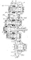
- an input shaft 2 means comprising two concentric input shafts 2a and 2b, a first countershaft 3, a second countershaft 4 and a reverse gear shaft 5 are rotatably mounted.
- Each input shaft 2a, 2b is adapted to be alternately connected to the crankshaft of an engine by means of a clutch (not shown) of its own.
- the input shaft 2a carries gear wheels 6 and 7 for 5 th and 3 rd gear speed, respectively, which are non-rotatably fixed to the shaft 2a while the input shaft 2b carries gear wheels 8, 9 and 10 for 4 th , 2 nd and 6 th gear speed, respectively, which are non-rotatably fixed to the shaft 2b.
- the gear wheels 6 and 7 on the input shaft 2a engage gear wheels 11 and 12, respectively which are rotatably journalled on the countershaft 4 but can be locked or released in a conventional manner by means of engaging sleeves 13 and 14, respectively, with associated synchronizing means.
- the gear wheels 8 and 10 on the input shaft 2b engage gear wheels 15 and 16 on the countershaft 3, repectively, while the gear wheel 9 on the input shaft 2b engages a gear wheel 17a on the countershaft 4. All gear wheels 15, 16 and 17a are rotatably journalled on their repective countershafts 3 and 4 but can be locked and released by means of an engaging sleeve 18 and the engaging sleeve 13, respectively.
- a gear wheel 17b is rigidly attached to the gear wheel 17a and thus is lockable to and releaseable from the countershaft 4 by means of the engaging sleeve 13.
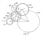
- the gear wheel 17b has a smaller diameter than the gear wheel 17a and engages a gear wheel 19 which is rotatably journalled and lockable to the reverse shaft 5 by means of an engaging sleeve 20 with associated synchronizing means.
- a pair of gear wheels 21 and 22 are each non-rotatably fixed to its respective countershaft 3 and 4 and each engages a crown wheel 23 of a differential generally designated 24.
- a gear wheel 25 is non-rotatably fixed to the reverse shaft 5 and engages the crown wheel 23. Since the gear ratio in reverse is dependent on among other things the diameter of a gear wheel 17b, the diameter of which is not governed by the diameter of any forward speed gear wheel, the diameters of the gear wheels 17b and 19 can be chosen so that a suitable gear ratio is obtained in reverse at the same time as the final drive gear wheel 25 can have the same diameter as the final drive gear wheels 21 and 22 on the countershafts.
- a gear wheel 30 is rotatably mounted on the reverse shaft 5.
- the gear wheel 30 can be locked to the shaft 5 by means of the engaging sleeve 20 and engages a gear wheel 31 which is non-rotatably mounted on a transfer shaft 32 located between the countershaft 4 and the reverse shaft 5.
- a gear wheel 33 non-rotatably mounted on the transfer shaft 32 engages the gear wheel 12 on the countershaft 4.
- gearbox torque is transferred in 3 rd and 5 th gear speeds from the input shaft 2a via the countershaft 4 and its non-rotatable gear wheel 22 to the crown wheel 23 and in 2 nd , 4 th and 6 th gear speeds from the input shaft 2b via the countershaft 3 and its gear wheel 21 to the crown wheel 23.
- Which gear wheel engage in respective gear speeds is evident from the figures and in addition to torque tranfer in reverse already described above only torque transfer i 1 st will be described in detail.
- the gearbox shown in Fig. 3 differs from the one discribed above only with respect to the torque transfer in 1 st gear. Only gear wheels tranferring torque in 1 st , 2 nd , 5 th and reverse gear has been provided with reference numerals which are the same as the ones shown in Fig. 1. As can be seen in Fig. 3 torque in 1 st gear is transferred to the gear wheel 33 on the tranfer shaft 32 from 5 th gear speed gear wheel 11 instead of 3 rd gear speed gear wheel 12 as shown in Fig. 1 and 2.
Claims (5)
- Kraftfahrzeuggetriebe mit einem Gehäuse (1) mit einer Eingangswelleneinrichtung (2) und zwei Gegenwellen (3, 4), die in einer von der Eingangswelleneinrichtung versetzten Ebene liegen und Zahnräder (11, 12, 15-17) aufweisen, die mit Zahnrädern (6-10) an der Eingangswelleneinrichtung in Eingriff sind, zum Übertragen eines Drehmoments mit einer Anzahl von Vorwärtsganggeschwindigkeiten, wobei zumindest ein Zahnrad von jedem Paar wechselseitig eingreifender Zahnräder an der Eingangswelleneinrichtung und den Gegenwellen von seiner Welle lösbar ist, wobei ein Zahnrad (19) zum Übertragen eines Drehmoments im Rückwärtsgang an einer vierten Welle (5) lösbar getragen wird, wobei jede der Gegenwellen und die vierte Welle ein Zahnrad (21, 22, 25) aufweisen, das mit seiner Welle nicht drehbar verbunden ist, zum Übertragen eines Drehmoments an ein Antriebskegelrad (23) eines Differentials (24), das die Zahnräder (21, 22, 25), die nicht drehbar mit den Gegenwellen (3, 4) und der vierten Welle (5) verbunden sind, in Eingriff nimmt, wobei das Zahnrad (19) zum Übertragen eines Drehmoments im Rückwärtsgang an der vierten Welle (5) eine Zahnradeinrichtung (17b) in Eingriff nimmt, die an einem lösbaren Vorwärtsganggeschwindigkeits-Zahnrad (17a) an einer (4) der Gegenwellen antreibend angebracht ist, wobei die Zahnradeinrichtung einen kleineren Durchmesser aufweist als der Durchmesser des Vorwärtsganggeschwindigkeits-Zahnrads und dass die Eingangswelleneinrichtung zumindest fünf Zahnräder (6-10) aufweist, im Eingriff mit den Zahnrädern (11, 12, 15-17) an den Gegenwellen (3, 4), zum Übertragen eines Drehmoments an das Antriebskegelrad (23) zum Vorwärtsantrieb mit zumindest fünf unterschiedlichen Ganggeschwindigkeiten, dadurch gekennzeichnet, dass ein lösbares Zahnrad (11, 12) an einer der Gegenwellen ein Zahnrad (33) an einer Übertragungswelle (32), zum Übertragen eines Drehmoments bei einer Vorwärtsganggeschwindigkeit an ein zahnrad (30) an der vierten Welle (5), in Eingriff nimmt, um ein Drehmoment zu übertragen, zum Vorwärtsantrieb mit einer zusätzlichen Ganggeschwindigkeit, die sich von den fünf unterschiedlichen Ganggeschwindigkeiten unterscheidet.
- Getriebe nach Anspruch 1, dadurch gekennzeichnet, dass die Zahnradeinrichtung (17b) ein Zahnrad ist, das nicht drehbar an einem Vorwärtsganggeschwindigkeits-Zahnrad (17a) angebracht ist.
- Getriebe nach Anspruch 1 oder 2, dadurch gekennzeichnet, dass das lösbare Zahnrad (19) an der vierten Welle (5) zum Übertragen eines Drehmoments im Rückwärtsgang ein Zahnrad (17b) in Eingriff nimmt, das an einem Zahnrad (17a) angebracht ist, das angeordnet ist, um ein Drehmoment in einer zweiten Vorwärtsganggeschwindigkeit zu übertragen.
- Getriebe nach einem der Ansprüche 1 bis 3, dadurch gekennzeichnet, dass die Zahnräder (21, 22, 25), die nicht drehbar mit den Gegenwellen (3, 4) und der vierten Welle (5) verbunden sind, den gleichen Durchmesser aufweisen.
- Getriebe nach einem der Ansprüche 1 bis 4, dadurch gekennzeichnet, dass die Eingangswelleneinrichtung (2) eine erste und eine zweite Eingangswelle (2a, 2b) umfasst, wobei die zweite Eingangswelle (2b) eine Hohlwelle ist, die konzentrisch um die erste Eingangswelle (2a) eingesetzt ist.
Priority Applications (2)
| Application Number | Priority Date | Filing Date | Title |
|---|---|---|---|
| EP20040010875 EP1593877B1 (de) | 2004-05-07 | 2004-05-07 | Fahrzeuggetriebe |
| DE200460009893 DE602004009893T2 (de) | 2004-05-07 | 2004-05-07 | Fahrzeuggetriebe |
Applications Claiming Priority (1)
| Application Number | Priority Date | Filing Date | Title |
|---|---|---|---|
| EP20040010875 EP1593877B1 (de) | 2004-05-07 | 2004-05-07 | Fahrzeuggetriebe |
Publications (2)
| Publication Number | Publication Date |
|---|---|
| EP1593877A1 EP1593877A1 (de) | 2005-11-09 |
| EP1593877B1 true EP1593877B1 (de) | 2007-11-07 |
Family
ID=34924901
Family Applications (1)
| Application Number | Title | Priority Date | Filing Date |
|---|---|---|---|
| EP20040010875 Expired - Fee Related EP1593877B1 (de) | 2004-05-07 | 2004-05-07 | Fahrzeuggetriebe |
Country Status (2)
| Country | Link |
|---|---|
| EP (1) | EP1593877B1 (de) |
| DE (1) | DE602004009893T2 (de) |
Families Citing this family (4)
| Publication number | Priority date | Publication date | Assignee | Title |
|---|---|---|---|---|
| JP4439479B2 (ja) * | 2006-02-24 | 2010-03-24 | ジヤトコ株式会社 | 自動車用変速機 |
| JP5022810B2 (ja) * | 2007-08-02 | 2012-09-12 | アイシン・エーアイ株式会社 | 6組の前進変速ギヤ対を有する変速機 |
| DE102009058710A1 (de) * | 2009-12-17 | 2011-06-22 | Volkswagen AG, 38440 | Kraftfahrzeuggetriebe |
| DE102011117452B4 (de) * | 2011-10-31 | 2019-05-16 | GM Global Technology Operations LLC (n. d. Gesetzen des Staates Delaware) | Manuell schaltbares 7-Gang Getriebe |
Family Cites Families (4)
| Publication number | Priority date | Publication date | Assignee | Title |
|---|---|---|---|---|
| SE502903C2 (sv) * | 1994-06-29 | 1996-02-19 | Volvo Ab | Motorfordonsväxellåda |
| SE504092C2 (sv) * | 1995-03-03 | 1996-11-11 | Volvo Ab | Motorfordonsväxellåda |
| EP1077336B1 (de) * | 1999-07-05 | 2002-03-20 | Ford Global Technologies, Inc., A subsidiary of Ford Motor Company | Getriebekonzept für ein 6-Gang-Vorgelege-Wechselgetriebe für Kraftfahrzeuge |
| EP1443245B1 (de) * | 2003-01-31 | 2010-03-10 | Volkswagen Aktiengesellschaft | Kraftfahrzeuggetriebe |
-
2004
- 2004-05-07 EP EP20040010875 patent/EP1593877B1/de not_active Expired - Fee Related
- 2004-05-07 DE DE200460009893 patent/DE602004009893T2/de not_active Expired - Lifetime
Also Published As
| Publication number | Publication date |
|---|---|
| EP1593877A1 (de) | 2005-11-09 |
| DE602004009893D1 (de) | 2007-12-20 |
| DE602004009893T2 (de) | 2008-08-28 |
Similar Documents
| Publication | Publication Date | Title |
|---|---|---|
| EP0764246B1 (de) | Kraftfahrzeuggetriebe | |
| US8443686B2 (en) | Seven speed dual clutch transmission | |
| KR101176870B1 (ko) | 트랜스미션 | |
| US9752654B2 (en) | Dual-clutch transmission | |
| EP3961065A1 (de) | Stromübertragungsvorrichtung | |
| US20220185095A1 (en) | Transmission Assembly for a Motor Vehicle Powertrain, Powertrain, and Method for Controlling Same | |
| GB2458899A (en) | Dual clutch transmission | |
| SE504092C2 (sv) | Motorfordonsväxellåda | |
| EP2870381B1 (de) | Getriebe mit einer ölpumpe | |
| US20190162274A1 (en) | Gear Mechanism for a Motor Vehicle | |
| US6485390B2 (en) | Transfer for four-wheel drive vehicle | |
| EP1593877B1 (de) | Fahrzeuggetriebe | |
| JP7042257B2 (ja) | 多段変速機 | |
| EP0469128A1 (de) | Getriebe für kraftfahrzeug. | |
| JPH06241288A (ja) | 歯車変速機 | |
| US6746356B2 (en) | Geared transmissions | |
| EP1599684B1 (de) | Kraftfahrzeuggetriebe | |
| EP1531286B1 (de) | Kraftfahrzeuggetriebe | |
| EP0242338B1 (de) | Getriebeeinheit für Motorfahrzeug | |
| US7448289B1 (en) | Manual transmission | |
| EP1531285B1 (de) | Kraftfahrzeuggetriebe | |
| US20120024095A1 (en) | Manual transmission | |
| JP2005505736A (ja) | カウンターシャフト構造のシフトギヤ | |
| JP6512175B2 (ja) | 手動変速機 | |
| SE513133C2 (sv) | Fordonsväxellåda med sex framåtväxlar |
Legal Events
| Date | Code | Title | Description |
|---|---|---|---|
| PUAI | Public reference made under article 153(3) epc to a published international application that has entered the european phase |
Free format text: ORIGINAL CODE: 0009012 |
|
| AK | Designated contracting states |
Kind code of ref document: A1 Designated state(s): AT BE BG CH CY CZ DE DK EE ES FI FR GB GR HU IE IT LI LU MC NL PL PT RO SE SI SK TR |
|
| AX | Request for extension of the european patent |
Extension state: AL HR LT LV MK |
|
| RAP1 | Party data changed (applicant data changed or rights of an application transferred) |
Owner name: FORD GLOBAL TECHNOLOGIES, LLC. |
|
| 17P | Request for examination filed |
Effective date: 20060427 |
|
| AKX | Designation fees paid |
Designated state(s): DE GB SE |
|
| GRAP | Despatch of communication of intention to grant a patent |
Free format text: ORIGINAL CODE: EPIDOSNIGR1 |
|
| GRAS | Grant fee paid |
Free format text: ORIGINAL CODE: EPIDOSNIGR3 |
|
| GRAA | (expected) grant |
Free format text: ORIGINAL CODE: 0009210 |
|
| AK | Designated contracting states |
Kind code of ref document: B1 Designated state(s): DE GB SE |
|
| REG | Reference to a national code |
Ref country code: GB Ref legal event code: FG4D |
|
| REF | Corresponds to: |
Ref document number: 602004009893 Country of ref document: DE Date of ref document: 20071220 Kind code of ref document: P |
|
| REG | Reference to a national code |
Ref country code: SE Ref legal event code: TRGR |
|
| PLBE | No opposition filed within time limit |
Free format text: ORIGINAL CODE: 0009261 |
|
| STAA | Information on the status of an ep patent application or granted ep patent |
Free format text: STATUS: NO OPPOSITION FILED WITHIN TIME LIMIT |
|
| 26N | No opposition filed |
Effective date: 20080808 |
|
| REG | Reference to a national code |
Ref country code: GB Ref legal event code: 732E Free format text: REGISTERED BETWEEN 20111020 AND 20111025 |
|
| REG | Reference to a national code |
Ref country code: DE Ref legal event code: R082 Ref document number: 602004009893 Country of ref document: DE Representative=s name: HOFFMANN - EITLE, DE |
|
| REG | Reference to a national code |
Ref country code: DE Ref legal event code: R081 Ref document number: 602004009893 Country of ref document: DE Owner name: VOLVO CAR CORPORATION, SE Free format text: FORMER OWNER: FORD GLOBAL TECHNOLOGIES, LLC (N.D.GES.D. STAATES DELAWARE), DEARBORN, US Effective date: 20120206 Ref country code: DE Ref legal event code: R082 Ref document number: 602004009893 Country of ref document: DE Representative=s name: HOFFMANN - EITLE, DE Effective date: 20120206 Ref country code: DE Ref legal event code: R081 Ref document number: 602004009893 Country of ref document: DE Owner name: VOLVO CAR CORPORATION, SE Free format text: FORMER OWNER: FORD GLOBAL TECHNOLOGIES, LLC (N.D.GES.D. STAATES DELAWARE), DEARBORN, MICH., US Effective date: 20120206 Ref country code: DE Ref legal event code: R082 Ref document number: 602004009893 Country of ref document: DE Representative=s name: HOFFMANN - EITLE PATENT- UND RECHTSANWAELTE PA, DE Effective date: 20120206 |
|
| PGFP | Annual fee paid to national office [announced via postgrant information from national office to epo] |
Ref country code: GB Payment date: 20140513 Year of fee payment: 11 |
|
| PGFP | Annual fee paid to national office [announced via postgrant information from national office to epo] |
Ref country code: DE Payment date: 20140512 Year of fee payment: 11 Ref country code: SE Payment date: 20140522 Year of fee payment: 11 |
|
| REG | Reference to a national code |
Ref country code: DE Ref legal event code: R119 Ref document number: 602004009893 Country of ref document: DE |
|
| GBPC | Gb: european patent ceased through non-payment of renewal fee |
Effective date: 20150507 |
|
| PG25 | Lapsed in a contracting state [announced via postgrant information from national office to epo] |
Ref country code: SE Free format text: LAPSE BECAUSE OF NON-PAYMENT OF DUE FEES Effective date: 20150508 |
|
| PG25 | Lapsed in a contracting state [announced via postgrant information from national office to epo] |
Ref country code: DE Free format text: LAPSE BECAUSE OF NON-PAYMENT OF DUE FEES Effective date: 20151201 Ref country code: GB Free format text: LAPSE BECAUSE OF NON-PAYMENT OF DUE FEES Effective date: 20150507 |