EP1592256A1 - Korrektur der Bildstatusinformation - Google Patents
Korrektur der Bildstatusinformation Download PDFInfo
- Publication number
- EP1592256A1 EP1592256A1 EP04010303A EP04010303A EP1592256A1 EP 1592256 A1 EP1592256 A1 EP 1592256A1 EP 04010303 A EP04010303 A EP 04010303A EP 04010303 A EP04010303 A EP 04010303A EP 1592256 A1 EP1592256 A1 EP 1592256A1
- Authority
- EP
- European Patent Office
- Prior art keywords
- image
- status information
- mode
- predefined
- video
- Prior art date
- Legal status (The legal status is an assumption and is not a legal conclusion. Google has not performed a legal analysis and makes no representation as to the accuracy of the status listed.)
- Granted
Links
Images


Classifications
-
- A—HUMAN NECESSITIES
- A46—BRUSHWARE
- A46B—BRUSHES
- A46B5/00—Brush bodies; Handles integral with brushware
- A46B5/002—Brush bodies; Handles integral with brushware having articulations, joints or flexible portions
- A46B5/0033—Brush bodies; Handles integral with brushware having articulations, joints or flexible portions bending or stretching or collapsing
- A46B5/0045—Brushes articulated with more than one hinge
-
- H—ELECTRICITY
- H04—ELECTRIC COMMUNICATION TECHNIQUE
- H04N—PICTORIAL COMMUNICATION, e.g. TELEVISION
- H04N7/00—Television systems
- H04N7/01—Conversion of standards, e.g. involving analogue television standards or digital television standards processed at pixel level
- H04N7/0112—Conversion of standards, e.g. involving analogue television standards or digital television standards processed at pixel level one of the standards corresponding to a cinematograph film standard
- H04N7/0115—Conversion of standards, e.g. involving analogue television standards or digital television standards processed at pixel level one of the standards corresponding to a cinematograph film standard with details on the detection of a particular field or frame pattern in the incoming video signal, e.g. 3:2 pull-down pattern
-
- A—HUMAN NECESSITIES
- A46—BRUSHWARE
- A46B—BRUSHES
- A46B15/00—Other brushes; Brushes with additional arrangements
- A46B15/0095—Brushes with a feature for storage after use
-
- A—HUMAN NECESSITIES
- A46—BRUSHWARE
- A46B—BRUSHES
- A46B2200/00—Brushes characterized by their functions, uses or applications
- A46B2200/10—For human or animal care
- A46B2200/1066—Toothbrush for cleaning the teeth or dentures
Definitions
- the present invention relates to an improved picture quality improvement processing.
- the present invention relates to a method for correcting status information accompanying video data and a corresponding image status information corrector.
- Picture improvement processing is employed in an increasing number of applications, in particular, in digital signal processing of modern television receivers.
- modern television receivers perform a frame-rate conversion, especially in form of a up-conversion or motion compensated up-conversion, for increasing the picture quality of the reproduced images.
- Motion compensated up-conversion is performed, for instance, for video sequences having a field or frame frequency of 50 Hz to higher frequencies like 60 Hz, 66.67 Hz, 75 Hz, 100 Hz, etc.
- a 50 Hz input signal frequency mainly applies to television signal broadcasts based on the PAL or SECAM television standards
- NTSC based video signals have an input frequency of 60 Hz.
- a 60 Hz input video signal may be up-converted to higher frequencies like 72 Hz, 80 Hz, 90 Hz, 120 Hz, etc.
- intermediate images are to be generated which reflect the video content at positions in time which are not represented by the 50 Hz or 60 Hz video sequence.
- the motion of moving objects has to be taken into account in order to appropriately reflect the changes between subsequent images caused by the motion of objects.
- the motion of objects is calculated on a block basis, and motion compensation is performed based on the relative position in time of the newly generated image between the previous and subsequent images.
- each image is divided into a plurality of blocks.
- Each block is subjected to motion estimation in order to detect a shift of an object from the previous image.
- High-end television sets and related devices perform frame rate conversion and image size scaling employing additional information related to the received image data.
- a film mode indication and further supplementary information is supporting the image processing.
- the film mode indication identifies whether or not the image data stem from a video camera (called “video mode” or “camera mode”) or from a motion picture film (called “film mode”).
- video mode a moving object is represented by different motion phases in each of the images in a video sequence. Thus, video mode can be detected by motion between each of the fields.
- film mode the images stem from a motion picture to interlaced video data conversion. Such a conversion generates two or three fields from the same film frame such that a particular motion/no motion pattern can be detected.
- a detection of film mode indications i.e. whether or not a current image is in video or film mode, is already known, for instance, from EP-A-1 198 137.
- the present invention aims to improve the quality of status information associated to image data in order to increase the reliability of the status information and to enable a more appropriate picture quality improvement processing.
- a method for correcting status information of video images is provided.
- the status information is assigned to each image element in a video image which comprises a plurality of image elements.
- the status information includes at least two different modes.
- the method counts the number of image elements having status information of a predetermined mode within a predefined image area.
- the count value is compared to a predetermined threshold. If the count value exceeds the threshold, all image elements of the predefined image area are set to the predetermined mode.
- an image status information corrector for correcting status information of video images.
- the status information is assigned to each image element in the video image comprising a plurality of image elements.
- the status information includes at least two different modes.
- the image status information corrector comprises a counter, a comparator, and a mode setter.
- the counter counts the number of image elements having status information of a predetermined mode within a predefined image area.
- the comparator compares the count value to a predetermined threshold.
- the mode setter sets aii image elements of the predefined image area to the predetermined mode If the count value exceeds this threshold.
- the status information is assigned to the video data in form of a local characteristic assigned to individual image elements.
- the status information of a predefined image area is evaluated and compared to the surrounding status information. If the evaluation reveals that the status assigned to a particular image element appears unreliable, this status information is corrected.
- the number of image elements having a particular status mode is counted. The count result is compared to a preset threshold. If the count value exceeds the threshold, it is assumed that image elements of another mode are unreliable irregularities and corrected accordingly. In this manner the reliability of status information can be increased and a subsequent image processing improved.
- the determination of characteristics of an image on a local basis may return particular image elements (blocks) not enabling a correct status determination.
- a concealment of such determination failures is achieved by the present invention, namely by referring to status information of other image elements/blocks within a predefined image area.
- the predefined image area comprises a predetermined number of block lines or block columns of a video image, most preferably a single block line or column of blocks. In this manner, all blocks of a line or column are analyzed and set to a particular mode if a threshold of a predetermined number blocks having that mode is detected.
- the predefined image area comprises a plurality of blocks within an area of a predetermined horizontal and vertical size.
- the image area evaluated for status information and correction can be set arbitrarily.
- the size of the image area may be set in accordance with the borders of image objects. In this manner, an image content related correction can be performed.
- the status information is a binary value.
- the modes of the status information preferably include a film mode/video mode.
- the status information includes a film mode and/or a motion pattern.
- the motion pattern preferably indicates a motion picture-to-interlaced conversion pattern. Accordingly, the image processing of interlaced fields can be appropriately performed based on status information of improved reliability.
- the count value is compared to a second predefined threshold and, if it turns out that the count value is smaller than the second threshold, all blocks are set to another mode of the status information. Accordingly, a mode correction can be achieved in a simple manner for more than one mode of said status information.
- the present invention relates to digital signal processing, especially to digital signal processing in modern television receivers.
- Modern television receivers employ up-conversion algorithms in order to increase the reproduced picture quality.
- intermediate images are to be generated from two subsequent images.
- the motion of moving objects has to be taken into account in order to appropriately adapt the object position to the point of time reflected by the interpolated image.
- Motion estimation for determining a motion vector and motion compensation are performed on a block basis.
- each image is divided into a plurality of blocks as illustrated, for example, in Fig. 1.
- Each block is individually subjected to motion estimation by determining a best matching block in the previous image.
- a film mode indication i.e. film mode or video mode
- the determination of a film mode indication is required.
- Such a video signal processing is particularly required to drive progressive displays and to make use of higher frame rates, in particular for HDTV display devices.
- the detection of motion picture film converted into interlaced image sequences for television broadcast (further referred to as film mode) is crucial for the signal processing.
- an interlaced/progressive conversion is possible in form of an inverse telecine processing, i.e. a re-interleaving of even and odd fields.
- an inverse telecine processing i.e. a re-interleaving of even and odd fields.
- More advanced up-conversion algorithms employ a motion vector based interpolation of frames.
- the output frame rate can be an uneven fraction of the input video rate for instance a 60 Hz input signal frequency may be up-converted to a 72 Hz output frequency corresponding to a ratio of 5:6. Accordingly, only every sixth output frame can be generated from a single input field alone when a continuous motion impression of moving objects is to be maintained.
- the film-mode characteristic of an image may be determined on a image basis or, according to an improved approach, be a local characteristic of individual image areas.
- television signals are composed of different types of image areas such as no-motion areas (e.g. logo, background), video camera areas (e.g. newsticker, video insertion) and film mode areas (e.g. main movie, PIP).
- no-motion areas e.g. logo, background
- video camera areas e.g. newsticker, video insertion
- film mode areas e.g. main movie, PIP.
- a pull down scheme detection is separately performed for each of these image areas enabling an up-conversion result with improved picture quality.
- Film mode detection generally involves a recognition of a pull down pattern.
- pixel differences are accumulated to a Displaced Frame Difference (DFD) representing the motion between subsequent images.
- DFD Displaced Frame Difference
- detection delays are employed for triggering a switch from a film mode to a video mode and vice versa.
- a film mode detection is performed on a block basis, as illustrated for instance in Fig. 1.
- a motion vector and film mode indication are determined for each block of a pixel size of m*n.
- a film mode indication is stored indicating whether the current block is film mode or video mode. Further, a correction of the assigned film mode indication is indicated by the "artificial mode" indication in order to distinguish an original film mode indication from a later correction thereof.
- the film mode determination is preferably based on luminance value differences between subsequent fields.
- the number of fields to be evaluated depends on the kind of motion pattern to be determined, i.e. whether a 2-2 pull down, a 3-2 pull down or a combination of both needs to be detected.
- the determination may fail for some of the blocks resulting in a missing or wrong determination result. These determination failures lead to a reduced performance of a subsequent image processing, in particular of interpolation algorithms.
- the film mode determination is preferably based on the respective differences of luminance values between two corresponding image blocks in subsequent fields.
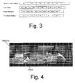
- the basic principle of film mode determination is illustrated in Fig. 3. As can be seen therefrom, two fields stem from a single motion picture film frame. The difference calculated between subsequent fields is dependent on whether the fields stem from the same or from a different motion picture film frame. Accordingly, a binary film mode pattern can be generated indicating a large difference by a logic "1" and a small difference by a logic "0". The binary values indicate whether or not motion is present between subsequent fields.
- the detected motion pattern is stored in a register and compared to predetermined reference patterns in order to detect the employed pull down scheme.
- the film mode determination is performed on a block basis as illustrated, for instance, in Fig. 1 and Fig. 4.
- the film mode determination mainly suffers from the following main problems. First, noise present in a video image distort the respective luminance values and may cause errors in the resulting mode determination.
- a very slow motion of an image object does not enable an accumulation result of differences exceeding the predefined threshold. Accordingly, the very slow motion may result in an incorrect film mode determination, incorrectly indicating video/camera mode although the respective images stem from a telecine conversion.
- unstructured areas within an image do not enable the detection of differences although motion may be present.
- An example for such a image portion which does not enable the detection of motion is illustrated in Fig. 5.
- FIG. 6 An example of film mode indications determined on a block basis is illustrated in Fig. 6.
- the illustrated example indicates four blocks labelled "C" which have been determined to be in camera mode C instead of film mode F.
- FIG. 5 film mode determination has failed for these image areas as these blocks relate to unstructured image portions and, consequently, do not enable a reliable film mode determination.
- These incorrectly determined film mode indications cause an inappropriate picture processing for these blocks resulting in a reduced picture quality perceived by the viewer.
- the present invention suggests analysing the film mode indications within a predefined image area and correcting the modes depending on the evaluated distribution of a particular mode.
- all film mode indications are evaluated for an individual line of pixels.
- the number of blocks in film mode is counted, and if the number of counted film mode blocks exceeds a predefined threshold, the mode for all blocks of that row is set to film mode.
- a video mode correction can be performed.
- the count value is further compared to a second threshold set in advance for video mode. If the count value is smaller than the second threshold, all blocks of the respective line are set to video mode.
- This processing is repeated for each line of blocks of a video image such that the reliability of determined characteristics for all blocks of the image is increased.
- the first threshold for correcting all detected modes of a block line to film mode is set to a value of around 95% of the total number of blocks per line.
- the second threshold for correcting the detected modes of a complete block line to video mode is preferably set to a value of around 5% of the total number of blocks per line.
- the values are set adaptively to the respective image content and transmission quality.
- the first threshold is set between a value of 85-98% of the total number of blocks per line, most preferably to a value between 90-96%.
- the lower threshold for camera mode corrections is set to a value between 2-15% of the total number of blocks per line, most preferably to a value between 4-10%.
- the values used for the thresholds depend on the quality of the block mode determination, block size and number of blocks.
- FIG. 7 A flow chart for performing the present invention is illustrated in Fig. 7. The described method of Fig. 7 is performed for each block line individually. After the evaluation of a block line has been started in step 110, the mode of the first block is obtained in step 120. If the obtained mode is film, step 130 branches to step 140 in order to increase the count value. Otherwise, step 130 branches to step 150 in order to determine whether or not the last block of a block line has been reached.
- the count value is increased upon each detection of a film mode block.
- the count value is compared to a first threshold value thrs_film in step 160. If the count value exceeds the threshold, all blocks of that line are set to film mode in step 170.
- the count value is further compared to a second threshold value thrs_camera in step 180. If the count value is smaller than the second threshold value, thrs_camera, all blocks of that row of blocks are set to video mode in step 190.
- the correction is not limited to an evaluation of blocks per line.
- the image blocks may be evaluated and corrected for each column of blocks in a video image, or alternatively, based on a plurality of combined rows or columns.
- the size and form of the image elements for which a mode information has been determined is not limited to blocks.
- the skilled person is aware that any kind of image elements can be used for this purpose.
- the present invention relates to a correction of image status information assigned on a local basis to a video image. Upon evaluating a predefined image portion comprising a plurality of image elements, incorrect determinations are detected and eliminated.
Landscapes
- Engineering & Computer Science (AREA)
- Multimedia (AREA)
- Signal Processing (AREA)
- Television Systems (AREA)
- Studio Devices (AREA)
- Image Processing (AREA)
- Image Analysis (AREA)
Priority Applications (6)
| Application Number | Priority Date | Filing Date | Title |
|---|---|---|---|
| DE602004021560T DE602004021560D1 (de) | 2004-04-30 | 2004-04-30 | Korrektur der Bildstatusinformation |
| EP04010303A EP1592256B1 (de) | 2004-04-30 | 2004-04-30 | Korrektur der Bildstatusinformation |
| JP2005129436A JP4791074B2 (ja) | 2004-04-30 | 2005-04-27 | 状態情報訂正方法、動き補償画像処理方法及び画像状態情報訂正器 |
| KR1020050035401A KR101140442B1 (ko) | 2004-04-30 | 2005-04-28 | 이미지 상태 정보의 정정 방법, 움직임 보상 이미지 처리방법, 및 이미지 상태 정보 정정기 |
| US11/117,577 US7385648B2 (en) | 2004-04-30 | 2005-04-29 | Image status information correction |
| CNB2005100762237A CN100477775C (zh) | 2004-04-30 | 2005-04-30 | 图像状态信息校正 |
Applications Claiming Priority (1)
| Application Number | Priority Date | Filing Date | Title |
|---|---|---|---|
| EP04010303A EP1592256B1 (de) | 2004-04-30 | 2004-04-30 | Korrektur der Bildstatusinformation |
Publications (2)
| Publication Number | Publication Date |
|---|---|
| EP1592256A1 true EP1592256A1 (de) | 2005-11-02 |
| EP1592256B1 EP1592256B1 (de) | 2009-06-17 |
Family
ID=34924807
Family Applications (1)
| Application Number | Title | Priority Date | Filing Date |
|---|---|---|---|
| EP04010303A Expired - Lifetime EP1592256B1 (de) | 2004-04-30 | 2004-04-30 | Korrektur der Bildstatusinformation |
Country Status (6)
| Country | Link |
|---|---|
| US (1) | US7385648B2 (de) |
| EP (1) | EP1592256B1 (de) |
| JP (1) | JP4791074B2 (de) |
| KR (1) | KR101140442B1 (de) |
| CN (1) | CN100477775C (de) |
| DE (1) | DE602004021560D1 (de) |
Cited By (1)
| Publication number | Priority date | Publication date | Assignee | Title |
|---|---|---|---|---|
| KR101140442B1 (ko) | 2004-04-30 | 2012-04-30 | 파나소닉 주식회사 | 이미지 상태 정보의 정정 방법, 움직임 보상 이미지 처리방법, 및 이미지 상태 정보 정정기 |
Families Citing this family (5)
| Publication number | Priority date | Publication date | Assignee | Title |
|---|---|---|---|---|
| JP4369948B2 (ja) * | 2006-09-20 | 2009-11-25 | シャープ株式会社 | 画像表示装置及び方法、画像処理装置及び方法 |
| JP4303743B2 (ja) * | 2006-10-04 | 2009-07-29 | シャープ株式会社 | 画像表示装置及び方法、画像処理装置及び方法 |
| KR101524062B1 (ko) * | 2008-07-30 | 2015-06-01 | 삼성전자주식회사 | 영상신호 처리장치 및 그 방법 |
| FR2939265A1 (fr) * | 2008-12-03 | 2010-06-04 | Thomson Licensing | Procede de detection de mode film ou mode camera |
| TWI410133B (zh) * | 2009-10-19 | 2013-09-21 | Himax Tech Ltd | 影片模式判斷方法 |
Citations (4)
| Publication number | Priority date | Publication date | Assignee | Title |
|---|---|---|---|---|
| US5734420A (en) * | 1994-12-13 | 1998-03-31 | Electronics And Telecommunications Research Institute | Film mode video sequence detector |
| US6031927A (en) * | 1993-12-02 | 2000-02-29 | General Instrument Corporation | Analyzer and methods for detecting and processing video data types in a video data stream |
| US20010002853A1 (en) * | 1999-12-02 | 2001-06-07 | Lg Electronics Inc. | Film mode detection method using periodic pattern of video sequence |
| EP1387577A2 (de) * | 2002-07-25 | 2004-02-04 | Samsung Electronics Co., Ltd. | Vorrichtung und Verfahren zur Aufhebung des Zeilensprungverfahrens |
Family Cites Families (11)
| Publication number | Priority date | Publication date | Assignee | Title |
|---|---|---|---|---|
| JP3199720B2 (ja) * | 1990-07-13 | 2001-08-20 | 株式会社日立製作所 | テレビジョン受像機および信号検出回路 |
| US5563651A (en) * | 1994-12-30 | 1996-10-08 | Thomson Consumer Electronics, Inc. | Method and apparatus for identifying video fields produced by film sources employing 2-2 and 3-2 pull down sequences |
| JP2001197363A (ja) * | 2000-01-06 | 2001-07-19 | Mitsubishi Electric Corp | テレシネ映像信号検出方法 |
| JP2002369156A (ja) * | 2001-06-11 | 2002-12-20 | Mitsubishi Electric Corp | 映像信号変換装置 |
| KR100398882B1 (ko) * | 2001-11-28 | 2003-09-19 | 삼성전자주식회사 | 필름모드 검출장치 및 방법 |
| JP2003179884A (ja) * | 2001-12-11 | 2003-06-27 | Sony Corp | プルダウン信号検出装置、プルダウン信号検出方法、高解像度化画像処理装置、高解像度化画像処理方法、画像符号化装置および画像符号化方法 |
| JP2003299092A (ja) * | 2002-04-03 | 2003-10-17 | Matsushita Electric Ind Co Ltd | 映像符号化装置 |
| KR100854091B1 (ko) * | 2002-07-13 | 2008-08-25 | 삼성전자주식회사 | 영상신호의 필름 모드 검출장치 및 방법 |
| KR100529308B1 (ko) * | 2002-09-17 | 2005-11-17 | 삼성전자주식회사 | 영상신호 처리에서의 필름 모드 검출 방법 및 장치 |
| US7075581B1 (en) * | 2003-06-03 | 2006-07-11 | Zoran Corporation | Interlaced-to-progressive scan conversion based on film source detection |
| EP1592256B1 (de) | 2004-04-30 | 2009-06-17 | Panasonic Corporation | Korrektur der Bildstatusinformation |
-
2004
- 2004-04-30 EP EP04010303A patent/EP1592256B1/de not_active Expired - Lifetime
- 2004-04-30 DE DE602004021560T patent/DE602004021560D1/de not_active Expired - Lifetime
-
2005
- 2005-04-27 JP JP2005129436A patent/JP4791074B2/ja not_active Expired - Fee Related
- 2005-04-28 KR KR1020050035401A patent/KR101140442B1/ko not_active Expired - Fee Related
- 2005-04-29 US US11/117,577 patent/US7385648B2/en not_active Expired - Fee Related
- 2005-04-30 CN CNB2005100762237A patent/CN100477775C/zh not_active Expired - Fee Related
Patent Citations (4)
| Publication number | Priority date | Publication date | Assignee | Title |
|---|---|---|---|---|
| US6031927A (en) * | 1993-12-02 | 2000-02-29 | General Instrument Corporation | Analyzer and methods for detecting and processing video data types in a video data stream |
| US5734420A (en) * | 1994-12-13 | 1998-03-31 | Electronics And Telecommunications Research Institute | Film mode video sequence detector |
| US20010002853A1 (en) * | 1999-12-02 | 2001-06-07 | Lg Electronics Inc. | Film mode detection method using periodic pattern of video sequence |
| EP1387577A2 (de) * | 2002-07-25 | 2004-02-04 | Samsung Electronics Co., Ltd. | Vorrichtung und Verfahren zur Aufhebung des Zeilensprungverfahrens |
Cited By (1)
| Publication number | Priority date | Publication date | Assignee | Title |
|---|---|---|---|---|
| KR101140442B1 (ko) | 2004-04-30 | 2012-04-30 | 파나소닉 주식회사 | 이미지 상태 정보의 정정 방법, 움직임 보상 이미지 처리방법, 및 이미지 상태 정보 정정기 |
Also Published As
| Publication number | Publication date |
|---|---|
| CN100477775C (zh) | 2009-04-08 |
| EP1592256B1 (de) | 2009-06-17 |
| JP2005318613A (ja) | 2005-11-10 |
| US20050243202A1 (en) | 2005-11-03 |
| CN1694525A (zh) | 2005-11-09 |
| KR20060047568A (ko) | 2006-05-18 |
| KR101140442B1 (ko) | 2012-04-30 |
| US7385648B2 (en) | 2008-06-10 |
| JP4791074B2 (ja) | 2011-10-12 |
| DE602004021560D1 (de) | 2009-07-30 |
Similar Documents
| Publication | Publication Date | Title |
|---|---|---|
| JP4253327B2 (ja) | 字幕検出装置及び字幕検出方法ならびにプルダウン信号検出装置 | |
| US20050249282A1 (en) | Film-mode detection in video sequences | |
| US6157412A (en) | System for identifying video fields generated from film sources | |
| EP1583364A1 (de) | Bewegungskompensierte Bildinterpolation an Bildrändern zur Bildfrequenzumwandlung | |
| WO2008152951A1 (en) | Method of and apparatus for frame rate conversion | |
| US20050243216A1 (en) | Block mode adaptive motion compensation | |
| US20050259950A1 (en) | Film mode correction in still areas | |
| US7443448B2 (en) | Apparatus to suppress artifacts of an image signal and method thereof | |
| US7385648B2 (en) | Image status information correction | |
| EP1592249B1 (de) | Umkehr-Filmmodus-Extrapolation | |
| EP1592254A1 (de) | Extrapolierung von Film-Mode | |
| CN101729841A (zh) | 梳状赝像检测装置和梳状赝像检测方法 | |
| JP5506550B2 (ja) | 映像信号処理装置及び方法、並びに映像信号表示装置 | |
| EP1592259B1 (de) | Verarbeitung von Hilfsdaten von Videosequenzen | |
| US7466361B2 (en) | Method and system for supporting motion in a motion adaptive deinterlacer with 3:2 pulldown (MAD32) | |
| US8233084B1 (en) | Method and system for detecting video field parity pattern of an interlaced video signal | |
| JP4092935B2 (ja) | 動きベクトル修正装置及び方法 | |
| Ojo et al. | Adaptive global concealment of video up-conversion artefacts | |
| JP2002335441A (ja) | テレシネ映像信号検出装置 | |
| KR100987770B1 (ko) | 비월 주사 영상 신호의 필드간 장면 전환시의 화면 깨짐현상을 최소화한 ipc 시스템 |
Legal Events
| Date | Code | Title | Description |
|---|---|---|---|
| PUAI | Public reference made under article 153(3) epc to a published international application that has entered the european phase |
Free format text: ORIGINAL CODE: 0009012 |
|
| 17P | Request for examination filed |
Effective date: 20050308 |
|
| AK | Designated contracting states |
Kind code of ref document: A1 Designated state(s): AT BE BG CH CY CZ DE DK EE ES FI FR GB GR HU IE IT LI LU MC NL PL PT RO SE SI SK TR |
|
| AX | Request for extension of the european patent |
Extension state: AL HR LT LV MK |
|
| AKX | Designation fees paid |
Designated state(s): DE FR GB |
|
| RAP1 | Party data changed (applicant data changed or rights of an application transferred) |
Owner name: PANASONIC CORPORATION |
|
| GRAP | Despatch of communication of intention to grant a patent |
Free format text: ORIGINAL CODE: EPIDOSNIGR1 |
|
| GRAS | Grant fee paid |
Free format text: ORIGINAL CODE: EPIDOSNIGR3 |
|
| GRAA | (expected) grant |
Free format text: ORIGINAL CODE: 0009210 |
|
| AK | Designated contracting states |
Kind code of ref document: B1 Designated state(s): DE FR GB |
|
| REG | Reference to a national code |
Ref country code: GB Ref legal event code: FG4D |
|
| REF | Corresponds to: |
Ref document number: 602004021560 Country of ref document: DE Date of ref document: 20090730 Kind code of ref document: P |
|
| PLBE | No opposition filed within time limit |
Free format text: ORIGINAL CODE: 0009261 |
|
| STAA | Information on the status of an ep patent application or granted ep patent |
Free format text: STATUS: NO OPPOSITION FILED WITHIN TIME LIMIT |
|
| 26N | No opposition filed |
Effective date: 20100318 |
|
| PGFP | Annual fee paid to national office [announced via postgrant information from national office to epo] |
Ref country code: DE Payment date: 20120502 Year of fee payment: 9 |
|
| PGFP | Annual fee paid to national office [announced via postgrant information from national office to epo] |
Ref country code: GB Payment date: 20120425 Year of fee payment: 9 Ref country code: FR Payment date: 20120504 Year of fee payment: 9 |
|
| GBPC | Gb: european patent ceased through non-payment of renewal fee |
Effective date: 20130430 |
|
| PG25 | Lapsed in a contracting state [announced via postgrant information from national office to epo] |
Ref country code: DE Free format text: LAPSE BECAUSE OF NON-PAYMENT OF DUE FEES Effective date: 20131101 Ref country code: GB Free format text: LAPSE BECAUSE OF NON-PAYMENT OF DUE FEES Effective date: 20130430 |
|
| REG | Reference to a national code |
Ref country code: FR Ref legal event code: ST Effective date: 20131231 |
|
| REG | Reference to a national code |
Ref country code: DE Ref legal event code: R119 Ref document number: 602004021560 Country of ref document: DE Effective date: 20131101 |
|
| PG25 | Lapsed in a contracting state [announced via postgrant information from national office to epo] |
Ref country code: FR Free format text: LAPSE BECAUSE OF NON-PAYMENT OF DUE FEES Effective date: 20130430 |