EP1592094B1 - Housing assembly and a pair of electric connectors using it - Google Patents
Housing assembly and a pair of electric connectors using it Download PDFInfo
- Publication number
- EP1592094B1 EP1592094B1 EP05252573.0A EP05252573A EP1592094B1 EP 1592094 B1 EP1592094 B1 EP 1592094B1 EP 05252573 A EP05252573 A EP 05252573A EP 1592094 B1 EP1592094 B1 EP 1592094B1
- Authority
- EP
- European Patent Office
- Prior art keywords
- housing
- reinforcing member
- fitting
- lock arm
- protruding parts
- Prior art date
- Legal status (The legal status is an assumption and is not a legal conclusion. Google has not performed a legal analysis and makes no representation as to the accuracy of the status listed.)
- Expired - Lifetime
Links
Images


Classifications
-
- H—ELECTRICITY
- H01—ELECTRIC ELEMENTS
- H01R—ELECTRICALLY-CONDUCTIVE CONNECTIONS; STRUCTURAL ASSOCIATIONS OF A PLURALITY OF MUTUALLY-INSULATED ELECTRICAL CONNECTING ELEMENTS; COUPLING DEVICES; CURRENT COLLECTORS
- H01R13/00—Details of coupling devices of the kinds covered by groups H01R12/70 or H01R24/00 - H01R33/00
- H01R13/64—Means for preventing incorrect coupling
- H01R13/641—Means for preventing incorrect coupling by indicating incorrect coupling; by indicating correct or full engagement
-
- H—ELECTRICITY
- H01—ELECTRIC ELEMENTS
- H01R—ELECTRICALLY-CONDUCTIVE CONNECTIONS; STRUCTURAL ASSOCIATIONS OF A PLURALITY OF MUTUALLY-INSULATED ELECTRICAL CONNECTING ELEMENTS; COUPLING DEVICES; CURRENT COLLECTORS
- H01R13/00—Details of coupling devices of the kinds covered by groups H01R12/70 or H01R24/00 - H01R33/00
- H01R13/62—Means for facilitating engagement or disengagement of coupling parts or for holding them in engagement
- H01R13/627—Snap or like fastening
- H01R13/6271—Latching means integral with the housing
- H01R13/6272—Latching means integral with the housing comprising a single latching arm
-
- H—ELECTRICITY
- H01—ELECTRIC ELEMENTS
- H01R—ELECTRICALLY-CONDUCTIVE CONNECTIONS; STRUCTURAL ASSOCIATIONS OF A PLURALITY OF MUTUALLY-INSULATED ELECTRICAL CONNECTING ELEMENTS; COUPLING DEVICES; CURRENT COLLECTORS
- H01R13/00—Details of coupling devices of the kinds covered by groups H01R12/70 or H01R24/00 - H01R33/00
- H01R13/62—Means for facilitating engagement or disengagement of coupling parts or for holding them in engagement
- H01R13/639—Additional means for holding or locking coupling parts together, after engagement, e.g. separate keylock, retainer strap
Definitions
- the present invention relates to housing assemblies which comprise a pair of insulating housings of a pair of electrical connectors, which can be coupled or uncoupled.
- Embodiments of the present invention belong to the field of electric connectors, and relate to a technique for confirming the fitting between a pair of electric connectors when they are fitted together and enhancing their coupling strength.
- Japanese Unexamined Patent Publication Heisei 9-17505 discloses a connector assembly with a fitting guaranteeing device wherein a fitting guaranteeing device comprising a fixing beam and a flexible beam is temporarily fitted on an outside surface of one of a pair of connector housings that can be fitted together in such a way that said fitting guaranteeing device will slide to a regular fitting position only when said pair of connector housings fit together, when said fitting guaranteeing device slides to said regular fitting position, said fixing beam will shift exposed on said outside surface, said flexible beam will be flexed inward to fit with a fitting lock means of said pair of connector housings so as to prevent unlocking of said fitting lock means.
- this connector assembly with a fitting guaranteeing device, firstly, unlocking of the fitting lock can be prevented reliably, and the operator can easily and properly judge, through senses of vision and touch, whether the connector housings are fitted together completely, mainly on the basis of the position of the fixing beam, and secondly, the operation of fitting the connectors together can be done relatively easily and reliably by temporarily fitting the fitting guaranteeing device on the connector housing.
- Embodiments of the present invention can provide a reinforcing member apart from a lock arm, wherein said reinforcing member is to be held by a first housing, said reinforcing member can be pushed into the first housing only when the first housing and the second housing are fitted together, to enhance the coupling strength of both the housings based on the lock arm by adding the coupling strength based on the reinforcing member, to enable the operator to judge easily and reliably whether both housings are fitted together on the basis of that the reinforcing member can be pushed in, to ensure smooth and reliable insertion work by holding the reinforcing member by the first housing, and to slim both housings.
- Embodiments of the present invention can also accomplish a single-action fitting wherein the first housing is fitted into the second housing by only pushing the reinforcing member rearward.
- a housing assembly comprising a first housing and a second housing being insulating housings of a pair of electric connectors to be coupled or uncoupled, and a reinforcing member for enhancing the coupling strength of these housings, wherein when a depth direction, a width direction and a height direction all being perpendicular to each other are assumed, the second housing is provided with a cavity, which opens on the front side in the depth direction and into which the first housing is to be fitted, the first housing is provided with a lock arm, which extends from the rear side to the front side in the depth direction and can be flexed to the lower side and is provided with a lock pawl on the higher side thereof, of walls facing the cavity in the second housing, a wall on the higher side in relation to the cavity is provided with a fitting part, which fits with the lock pawl when the lock arm shifts rearward and only after the lock pawl gets over the fitting part through flexure of the lock arm, the first housing is provided with a receiving
- both the first housing and the second housing When contacts are added so that both the first housing and the second housing are provided with contacts, they will become a pair of electric connectors, and when the first housing fits in the second housing, the respective contacts of the housings will contact each other. When the first housing is withdrawn out of the second housing, the contacts of both housings will be separated from each other.
- the first housing When the reinforcing member is held at the front side position by fitting the top-end-side concaved parts with the first protruding parts, the first housing is inserted into the cavity of the second housing, and the reinforcing member or the first housing is pushed rearward toward the second housing, the lock arm will be pushed by the fitting part of the second housing to flex to the lower side, the flexed lock arm will interfere with or will be able to interfere with the reinforcing member and prevent the reinforcing member from sliding rearward into the first housing, and the fitting arms will run into the second protruding parts to move to both sides in the width direction and release the top-end-side concaved parts from the first protruding parts.
- the lock pawl When the first housing fits in the cavity of the second housing, the lock pawl will get over the fitting part of the second housing and after that the lock arm will restore itself and the lock pawl will fit with the fitting part, and as a result of this, the reinforcing member will be allowed to slide rearward into the first housing.
- the fitting arms When the reinforcing member is pushed to the rear side position in relation to the first housing, the fitting arms will restore themselves due to their flexibility, and in turn, the root-end-side concaved parts will fit with the first protruding parts and the second protruding parts. As described above, the reinforcing member never slides from the front side position to the rear side position before the first housing is fitted in the second housing.
- the flexed lock arm will interfere with or will be able to interfere with the reinforcing member to prevent the reinforcing member from sliding rearward into the first housing, thus it will not be possible to push the reinforcing member rearward, and on the basis of this, the operator can easily and properly judge that the first housing is not fitted in the second housing, thus defective fitting can be prevented.
- the reinforcing member is prevented from dropping out of the housing assembly, and the fitting work can be done smoothly and reliably.
- the fitting arms of the reinforcing member flex in the width direction, the first housing and the second housing can be slimmed more in the height direction in comparison with the conventional connector housings, which are provided with a flexible beam that flexes in the height direction.
- the housing assembly of the present invention is so structured that the housing assembly is provided with a reinforcing member apart from a lock arm, the reinforcing member is held by the first housing, and the reinforcing member can be pushed into the first housing only when the first housing and the second housing are fitted together
- the housing assembly of the present invention enhances the coupling strength of both the housings based on the lock arm by adding the coupling strength based on the reinforcing member, enables the operator to judge easily and reliably whether both housings are fitted together on the basis of that the reinforcing member can be pushed in, ensures smooth and reliable insertion work by holding the reinforcing member by the first housing, and allows slimming of both housings.
- the housing assembly of the present invention allows a single-action fitting wherein the first housing is fitted into the second housing by only pushing the reinforcing member rearward, while reliably preventing errors of the reinforcing member.
- the housing assembly of the present invention may be so structured that in said housing assembly, when the reinforcing member is at the front side position, there is a clearance in the height direction between the reinforcing member and the lock arm, the clearance allows the lock arm to flex and in turn enables fitting between the lock pawl and the fitting part and undoing such fitting, and when the reinforcing member is at the rear side position, said clearance is closed up to prevent the lock arm from flexing and in turn disables undoing of the fitting between the lock pawl and the fitting part.
- the housing assembly of the present invention may be so structured that in said housing assembly, the reinforcing member is provided with a protrusion that will contact the lock arm when the lock arm interferes with the reinforcing member.
- the lock arm when the lock arm interferes with the reinforcing member, the lock arm will contact the protrusion. Hence the contact area will be smaller than a contact area that results when the lock arm makes plane contact with the surface of the reinforcing member. This reduces the possibility of occurrence of a trouble wherein due to frictions, the lock arm does not restore itself and is kept flexed and in turn the lock pawl and the fitting part do not fit together.
- the housing assembly of the present invention may be so structured that in said housing assembly, the reinforcing member is provided, on the outer sides in the width direction of the fitting arms, with a pair of flexible holding arms extending substantially parallel to each other, from the body rearward in the depth direction, and each holding arm is provided with a hook part, which protrudes in the width direction to be caught on the first housing to prevent the reinforcing member from dropping forward in the depth direction.
- the housing assembly of the present invention may be so structured that in said housing assembly, the first housing or the second housing is provided with a contact.
- a pair of electric connectors of the present invention comprises said housing assembly of the present invention, a first contact provided in the first housing, and a second contact provided in the second housing, and the pair of electric connectors are so structured that when the first housing is fitted in the second housing, the first contact will contact the second contact, and when the first housing is pulled out of the second housing, the first contact will be separated from the second contact.
- the pair of electric connectors of the present invention can enhance the coupling strength of both the housings based on the lock arm by adding the coupling strength based on the reinforcing member, enable the operator to judge easily and reliably whether both housings are fitted together on the basis of that the reinforcing member can be pushed in, ensure smooth and reliable insertion work by holding the reinforcing member by the first housing, and slim both housings and in turn slim the electric connectors.
- said pair of electric connectors can accomplish a single-action fitting wherein the first housing is fitted into the second housing by only pushing the reinforcing member rearward, while reliably preventing errors of the reinforcing member.
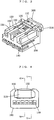
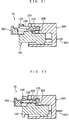
- Fig. 1 through Fig. 16 illustrate a housing assembly H of the embodiment of the present invention.
- the housing assembly H comprises a first housing 100 and a second housing 200 both being the insulating housings of the pair of electric connectors to be coupled together or to be disconnected from each other, and a reinforcing member 300 for enhancing the coupling strength between the housings 100, 200.
- the housing assembly H will become a pair of electric connectors when contacts are added so that both the first housing 100 and the second housing 200 are provided with contacts.
- the contacts of both housings will contact each other, and when the first housing 100 is pulled out of the second housing 200, these contacts will be separated.
- the second housing 200 is provided with the second contacts 500 by, for example, press-fitting or integral molding, and the first housing 100 is provided with chambers 140 penetrating through the housing in the depth direction and the first contacts 400 are to be fitted in these chambers 140. Because of this arrangement, in the stage of the housing assembly H, the first contacts 400 are not fitted yet, and when the first contacts 400 are fitted in the chambers 140, both the first housing 100 and the second housing 200 will be provided with their respective contacts to become a pair of electric connectors.
- the present invention includes a housing assembly wherein a first housing is not provided with first contacts and a second housing is provided with second contacts, a housing assembly wherein a first housing is provided with first contacts and a second housing is not provided with second contacts, a housing assembly wherein a first housing is not provided with first contacts and a second housing is not provided with second contacts, and a housing assembly wherein either one of housings is provided with a part of contacts, as its embodiments.
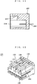
- the first housing 100 is formed of an insulating material into, for example, substantially a rectangular parallelepiped.
- the second housing 200 is formed of an insulating material into, for example, substantially a box shape, and the second housing 200 is provided with a cavity 210, which opens on the front in the depth direction and into which the first housing 100 is to be fitted.
- Both the first housing 100 and the second housing 200 are provided with locking mechanisms, which ensure or release the fitting engagement when the first housing 100 is fitted into the second housing 200.
- the first housing 100 is provided with a flexible lock arm 130.
- An end part 131 on the rear side of the lock arm 130 is fixed onto the first housing 100, and the lock arm 130 extends from the rear side in the depth direction frontward and can be flexed toward the lower side.
- the lock arm 130 is constituted of, for example, a part of the outer wall of the first housing 100, or the lock arm is arranged to extend along the outer wall of the first housing 100.
- the lock arm 130 is provided with, on its higher side in the height direction, a protruding lock pawl 133.
- the lock arm 130 is provided with a manipulation part 132 at the end on the front side, however, this manipulation part 132 may be either provided or not.
- this manipulation part 132 may be either provided or not.
- the wall facing the cavity 210 of the second housing 200 the wall being located on the higher side in relation to the cavity 210 is provided with raised fitting parts 230 protruding toward the lower side.
- the fitting part 230 may be plural or singular.
- the first housing 100 is provided with a receiving chamber 110, which penetrates into the first housing 100 in the depth direction.
- a reinforcing member 300 is inserted into this receiving chamber 110 in such a way that the reinforcing member 300 can slide in the depth direction.
- the reinforcing member 300 is provided with a body 310 serving as a manipulation part, and a pair of fitting arms 320 extending from the body 310 rearward in the depth direction as will be described later.
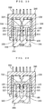
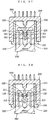
- the reinforcing member 300 is inserted into the receiving chamber 110 in such a way that the member can be slid between a front side position wherein the body 310 is on the front side, in the depth direction, of the first housing (the position illustrated in Fig. 17 through Fig. 19 , Fig. 21 through Fig. 23 , and Fig. 25 through Fig. 27 ) and a rear side position being on the rear side, in the depth direction, of the front side position (the position shown in Fig. 20 , Fig. 24 and Fig. 30 ).
- the first protruding parts 120 are located to protrude to both sides in the width direction, and the first protruding parts 120 are fixed on the first housing 100.
- the second protruding parts 220 are located to protrude to both sides in the width direction, and the second protruding parts 220 are fixed on the second housing 200.
- the reinforcing member 300 is provided with a pair of flexible fitting arms 320, which extend from the body 310 to the rear in the depth direction. This pair of fitting arms 320 are provided in the width direction so that they are parallel to each other. Each fitting arm 320 is provided with a top-end-side concaved part 321, which concaves from the inner side toward the outer side in the width direction and is to fit with the first protruding part 120 when the reinforcing member 300 is at the front side position.
- each fitting arm 320 is provided with a root-end side concaved part 322, which concaves from the inner side toward the outer side in the width direction on the front side of the top-end-side concaved part 321 in the depth direction and which is to fit with the first protruding part 120 and the second protruding part 220 when the first housing 100 fits in the cavity 210 of the second housing 200 and the reinforcing member 300 is at the rear side position.
- the inner side in the width direction of the fitting arm 320 is on the near side to the other fitting arm 320, and the outer side in the width direction of the fitting arm 320 is on the far side from the other fitting arm 320.
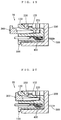
- This housing assembly H is structured to function as follows. First, as shown in Fig. 3 , Fig. 5 and Fig. 6 , the reinforcing member 300 is held at the front side position by fitting the top-end-side concaved parts 321 and the first protruding parts 120 together. Next, as shown in Fig. 17 , Fig. 21 and Fig. 25 , the first housing 100 is inserted into the cavity 210 of the second housing 200. When the reinforcing member 300 or the first housing 100 is pushed rearward toward the second housing 200, as shown in Fig. 18 and Fig.
- the flexed lock arm 130 will interfere with or will be able to interfere with the reinforcing member 300 to prevent the reinforcing member 300 from sliding rearward into the first housing 100, and as shown in Fig 26 the fitting arms 320 will be pushed by the second protruding parts 220 to move to both sides in the width direction, in other words, the fitting arms 320 will move outward in the width direction, respectively, and this in turn will release the top-end-side concaved parts 321 from the first protruding parts 120.
- the expression that the flexed lock arm 130 interferes with the reinforcing member 300 means that the flexed lock arm 130 directly contacts the reinforcing member 300.
- the expression that the flexed lock arm 130 will be able to interfere with the reinforcing member 300 means that although the flexed lock arm 130 is not contacting the reinforcing member 300, but if under the same condition the reinforcing member 300 is pushed rearward, the reinforcing member 300 will directly contact the flexed lock arm 130. This occurs, for example, when the first housing 100 is pushed rearward toward the second housing 200.
- the lock arm 130 will resume its free state and return upward due to fitting between the lock pawl 133 and the fitting parts 230, allowing the reinforcing member 300 to slide rearward into the first housing 100 (the state illustrated in Fig. 1 , Fig. 19 , Fig. 23 and Fig. 27 ). As shown in Fig. 28 and Fig.
- the operation ranging from starting to insert the first housing 100 into the cavity 210 of the second housing 200 to fitting the root-end-side concaved parts 322 with the first protruding parts 120 and the second protruding parts 220 is done by a single-action operation wherein only the reinforcing member 300 is pushed to effect a series of actions all at once or by a two-action operation wherein actions are done in two stages.
- the force pushing the reinforcing member 300 is transmitted to the first housing 100 by the fitting relationship between the top-end-side concaved parts 321 of the fitting arms 320 and the first protruding parts 120.
- the first operation is to push the first housing 100 rearward into the second housing 200.
- Actions ranging from starting to insert the first housing 100 into the cavity 210 of the second housing 200 to fitting the first housing 100 into the cavity 210 of the second housing 200 are done by this first operation.
- the top-end-side concaved parts 321 will be released from the first protruding parts 120, and the flexed lock arm 130 will interfere with or will be able to interfere with the reinforcing member 300, and the lock arm 130 will restore itself.
- the force pushing the reinforcing member 300 will become a force making the reinforcing member 300 slide rearward into the first housing 100, and this will fit the root-end-side concaved parts 322 with the first protruding parts 120 and the second protruding parts 220.
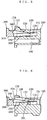
- This housing assembly H is so structured, as shown in Fig. 17 , that when the reinforcing member 300 is at the front side position, there is a clearance L in the height direction between the reinforcing member 300 and the lock arm 130, and this clearance L allows the lock arm 130 to flex and in turn enables fitting between the lock pawl 133 and the fitting parts 230 and undoing such fitting, and when the reinforcing member 300 is at the rear side position as shown in Fig. 20 , the above-mentioned clearance L is closed up to prevent the lock arm 130 from flexing and in turn disables undoing of the fitting between the lock pawl 133 and the fitting parts 230.
- the reinforcing member 300 is provided with protrusions 340, which contact the lock arm 130 when the lock arm 130 interferes with the reinforcing member 300.
- protrusions 340 are formed on the body 310 of the reinforcing member 300 to protrude rearward in the depth direction, and are so structured that when the lock arm 130 is pushed by the fitting parts 230 to flex to the lower side, the contact area between the frontward-facing face of the end part 134 on the front side in the depth direction of the lock arm 130 will be smaller than a contact area that results when the frontward-facing face of the above-mentioned end part 134 of the lock arm 130 makes plane contact with the surface of the body 310 of the reinforcing member 300.
- the protrusion 340 may be plural or singular.
- the above-mentioned reinforcing member 300 is provided, on the outer sides in the width direction of the fitting arms 320, with a pair of flexible holding arms 330 extending substantially parallel to each other, from the body 310 rearward in the depth direction, and each holding arm 330 is provided with a hook part 331 protruding in the width direction.
- the first housing 100 is provided with holding parts being concaved in the width direction. Thus when the hook parts 331 are held by the holding parts 150, the reinforcing member 300 can not come off forward in the depth direction.
- the housing assembly H of this embodiment when the first contacts 400 are mounted on the first housing 100, the housing assembly H will become a pair of electric connectors, and when the first housing 100 fits in the second housing 200, both the contacts 400 and the contacts 500 will contact each other, and when the first housing 100 is withdrawn out of the second housing 200, the contacts 400 and the contacts 500 will be separated from each other (refer to Fig. 17 through Fig. 20 ).
- the first housing 100 is inserted into the cavity 210 of the second housing 200, and the reinforcing member 300 or the first housing is pushed rearward toward the second housing 200, the lock arm 130 will be pushed by the fitting parts 230 of the second housing 200 to flex to the lower side, the flexed lock arm 130 will interfere with or will be able to interfere with the reinforcing member 300 and prevent the reinforcing member 300 from sliding rearward into the first housing 100, and the fitting arms 320 will run into the second protruding parts 220 to move to both sides in the width direction and release the top-end-side concaved parts 321 from the first protruding parts 120.
- the lock pawl 133 When the first housing 100 fits in the cavity 210 of the second housing 200, the lock pawl 133 will get over the fitting parts 230 of the second housing 200 and after that the lock arm 130 will restore itself and the lock pawl 133 will fit with the fitting parts 230, and as a result of this, the reinforcing member 300 will be allowed to slide rearward into the first housing 100.
- the fitting arms 320 When the reinforcing member 300 is pushed to the rear side position in relation to the first housing 100, the fitting arms 320 will restore themselves due to their flexibility, and in turn, the root-end-side concaved parts 322 will fit with the first protruding parts 120 and the second protruding parts 220.
- the reinforcing member 300 never slides from the front side position to the rear side position before the first housing 100 is fitted in the second housing 200. Hence errors such as that the top-end-side concaved parts 321 of the reinforcing member 300 fit with the second protruding parts 220 before the fitting of the housings 100, 200 and that root-end-side concaved parts 322 fit with the first protruding parts 120 or the second protruding parts 220 before the fitting of the housings 100, 200 are prevented. Moreover, the fitting with a single action, wherein only the reinforcing member 300 is pushed rearward to fit the first housing 100 into the second housing 200, can be made.
- the coupling strength due to this reinforcing member 300 is added to the coupling strength due to the fitting between the lock arm 130 and the fitting parts 230.
- the coupling strength between the first housing 100 and the second housing 200 is enhanced.
- the flexed lock arm 130 will interfere with or will be able to interfere with the reinforcing member 300 to prevent the reinforcing member 300 from sliding rearward into the first housing 100, thus it will not be possible to push the reinforcing member 300 rearward.
- the operator can easily and properly judge that the first housing 100 is not fitted in the second housing 200, thus defective fitting can be prevented.
- the reinforcing member 300 is held in the first housing 100 by the fitting of the top-end-side concaved parts 321 and the first protruding parts 120, the reinforcing member 300 is prevented from dropping out of the housing assembly H, and the fitting work can be done smoothly and reliably.
- the first housing 100 and the second housing 200 can be slimed more in the height direction in comparison with the conventional connector housings, which are provided with a flexible beam that flexes in the height direction.
- the present invention does not limit the relative positional relationship between the reinforcing member and the lock arm when the reinforcing member is at the front side position or at the rear side position.
- the above-mentioned embodiment is so structured that when the reinforcing member 300 is at the front side position, there is a clearance L in the height direction between the reinforcing member 300 and the lock arm 130, and this clearance L allows the lock arm 130 to flex and in turn enables fitting between the lock pawl 133 and the fitting parts 230 and undoing such fitting, and when the reinforcing member 300 is at the rear side position, the above-mentioned clearance L is closed up to prevent the lock arm 130 from flexing and in turn disables undoing of the fitting between the lock pawl 133 and the fitting parts 230.
- the present invention includes an embodiment wherein the frontward-facing face of the end part on the front side in the depth direction of the lock arm makes, with substantially entire surface thereof, plane contact with the surface of the reinforcing member.
- the reinforcing member 300 is provided with protrusions 340, which contact the frontward-facing face of the end part 134 on the front side in the depth direction of the lock arm 130 when the lock arm 130 interferes with the reinforcing member 300.
- the contact area will be smaller than a contact area that results when the substantially entire surface of the frontward-facing face of the end part 134 of the lock arm 130 makes plane contact with the surface of the reinforcing member 300. This reduces the possibility of occurrence of a trouble wherein due to frictions between two faces substantially facing in the depth direction, the lock arm 130 does not restore itself and is kept flexed and in turn the lock pawl 133 and the fitting parts 230 do not fit together.
- the present invention includes an embodiment wherein the reinforcing member is not provided with a holding arm.
- the reinforcing member 300 is provided, on the outer sides in the width direction of the fitting arms 320, with a pair of flexible holding arms 330 extending substantially parallel to each other, from the body 310 rearward in the depth direction, and each holding arm 330 is provided with a hook part 331 protruding in the width direction.
- This hook part 331 is to be caught on the first housing 100 to prevent the reinforcing member 300 from dropping forward in the depth direction.
- the reinforcing member 300 can not drop out of the first housing 100.
- the present invention does not limit the configurations of the contacting parts of both the fitting arms and the second protruding parts.
- Fig. 25 through Fig. 30 if the edge part on the inner side in the width direction and at the rear end of each fitting arm 320 is chamfered, when the fitting arms 320 run into the second protruding parts 220 to move to both sides in the width direction, this action will be done smoothly, hence it is preferable to do so.
- the edge parts at both ends in the width direction and at the front side end of the second protruding parts may be chamfered. Or they may be used together.
- the flexed lock arm 130 interferes with or is able to interfere with the reinforcing member 300 to prevent the reinforcing member 300 from sliding rearward into the first housing 100 immediately after the start of inserting the first housing 100 into the second housing 200. It is sufficient to start the action before the action, wherein the fitting arms 320 run into the second protruding parts 220 to move to both sides in the width direction and release the top-end-side concaved parts 321 from the first protruding parts 120, takes place.
- the housing assembly wherein the first housing or the second housing is provided with a contact has been disclosed.
- the pair of electric connectors which comprise the housing assembly of the present invention, the first contact provided in the first housing and the second contact provided in the second housing, and is so structured that when the first housing is fitted with the second housing, the first contact will connect to the second contact, and when the first housing is pulled out of the second housing, the first contact will be separated from the second contact, have been fully disclosed.
Landscapes
- Details Of Connecting Devices For Male And Female Coupling (AREA)
Applications Claiming Priority (2)
| Application Number | Priority Date | Filing Date | Title |
|---|---|---|---|
| JP2004134917 | 2004-04-28 | ||
| JP2004134917A JP4133922B2 (ja) | 2004-04-28 | 2004-04-28 | ハウジング組立体及びこれを用いた一対の電気コネクタ |
Publications (2)
| Publication Number | Publication Date |
|---|---|
| EP1592094A1 EP1592094A1 (en) | 2005-11-02 |
| EP1592094B1 true EP1592094B1 (en) | 2016-07-06 |
Family
ID=34941016
Family Applications (1)
| Application Number | Title | Priority Date | Filing Date |
|---|---|---|---|
| EP05252573.0A Expired - Lifetime EP1592094B1 (en) | 2004-04-28 | 2005-04-25 | Housing assembly and a pair of electric connectors using it |
Country Status (3)
| Country | Link |
|---|---|
| US (1) | US7048568B2 (enExample) |
| EP (1) | EP1592094B1 (enExample) |
| JP (1) | JP4133922B2 (enExample) |
Families Citing this family (9)
| Publication number | Priority date | Publication date | Assignee | Title |
|---|---|---|---|---|
| US7470138B1 (en) * | 2007-07-18 | 2008-12-30 | J.S.T. Corporation | Connector position assurance device and connector assembly apparatus incorporating the same |
| US8616974B2 (en) * | 2008-07-10 | 2013-12-31 | Sixense Entertainment, Inc. | Passive and active video game controllers with magnetic position sensing |
| DE102012221115A1 (de) * | 2012-11-19 | 2014-05-22 | Tyco Electronics Amp Gmbh | Steckerelement mit Kontaktmodulverrastung |
| KR101475861B1 (ko) * | 2014-07-09 | 2014-12-23 | 안창훈 | 랜 포트락장치 |
| JP6515825B2 (ja) * | 2016-01-21 | 2019-05-22 | 住友電装株式会社 | コネクタ |
| US10038278B2 (en) * | 2016-03-17 | 2018-07-31 | Te Connectivity Corporation | Electrical connector having a connector position assurance element |
| JP6852812B2 (ja) * | 2017-12-26 | 2021-03-31 | 住友電装株式会社 | コネクタ |
| JP2021005519A (ja) * | 2019-06-27 | 2021-01-14 | 住友電装株式会社 | コネクタ |
| DE102020127203B4 (de) * | 2020-10-15 | 2022-10-06 | Md Elektronik Gmbh | Steckverbinderanordnung |
Family Cites Families (14)
| Publication number | Priority date | Publication date | Assignee | Title |
|---|---|---|---|---|
| US4634204A (en) | 1985-12-24 | 1987-01-06 | General Motors Corporation | Electrical connector with connector position assurance/assist device |
| JPH0425817Y2 (enExample) * | 1988-01-22 | 1992-06-22 | ||
| JPH0433666Y2 (enExample) | 1988-05-13 | 1992-08-12 | ||
| JPH0743971Y2 (ja) * | 1988-10-17 | 1995-10-09 | マツダ株式会社 | コネクタ装置 |
| JP2537302B2 (ja) | 1990-03-01 | 1996-09-25 | 矢崎総業株式会社 | 電気コネクタのロック確認装置 |
| US5120255A (en) * | 1990-03-01 | 1992-06-09 | Yazaki Corporation | Complete locking confirming device for confirming the complete locking of an electric connector |
| JP2932902B2 (ja) * | 1993-08-03 | 1999-08-09 | 住友電装株式会社 | コネクタ |
| JP3170178B2 (ja) * | 1995-06-12 | 2001-05-28 | 矢崎総業株式会社 | コネクタの誤結合防止装置 |
| US5681178A (en) * | 1995-06-27 | 1997-10-28 | The Whitaker Corporation | Electrical connector with connector position assurance device |
| JPH1126089A (ja) * | 1997-07-08 | 1999-01-29 | Yazaki Corp | ロック検知コネクタ |
| JP2001185290A (ja) | 1999-12-27 | 2001-07-06 | Sumitomo Wiring Syst Ltd | コネクタ |
| JP3800312B2 (ja) * | 2000-10-31 | 2006-07-26 | 住友電装株式会社 | コネクタ |
| JP2002164125A (ja) * | 2000-11-27 | 2002-06-07 | Sumitomo Wiring Syst Ltd | コネクタ |
| JP2004079483A (ja) * | 2002-08-22 | 2004-03-11 | Sumitomo Wiring Syst Ltd | コネクタ |
-
2004
- 2004-04-28 JP JP2004134917A patent/JP4133922B2/ja not_active Expired - Lifetime
-
2005
- 2005-04-07 US US11/101,745 patent/US7048568B2/en not_active Expired - Lifetime
- 2005-04-25 EP EP05252573.0A patent/EP1592094B1/en not_active Expired - Lifetime
Also Published As
| Publication number | Publication date |
|---|---|
| US20050245122A1 (en) | 2005-11-03 |
| US7048568B2 (en) | 2006-05-23 |
| JP4133922B2 (ja) | 2008-08-13 |
| EP1592094A1 (en) | 2005-11-02 |
| JP2005317401A (ja) | 2005-11-10 |
Similar Documents
| Publication | Publication Date | Title |
|---|---|---|
| EP1054481B1 (en) | A connector | |
| US6644992B2 (en) | Lever-type connector | |
| EP0993077B1 (en) | Half-fitting prevention connector and method of producing same | |
| EP1049213A1 (en) | Connector fitting structure | |
| US7347704B2 (en) | Connector | |
| CN101218714B (zh) | 带有接线端位置保证装置的连接器组件 | |
| EP1571734B1 (en) | Connector apparatus with a mating detecting member called connector position assurance | |
| CN112688106B (zh) | 连接器 | |
| EP1033788B1 (en) | Connector with secondary locking | |
| EP1085617B1 (en) | A connector | |
| JP2019133758A (ja) | コネクタ | |
| EP1592094B1 (en) | Housing assembly and a pair of electric connectors using it | |
| JP2004063115A (ja) | コネクタ | |
| EP0660451B1 (en) | Connector | |
| US7001215B2 (en) | Connector with inner and outer housings | |
| US7445474B2 (en) | Lever-type connector and lever-type connector assembly | |
| EP1094559B1 (en) | Electrical connector having a terminal retainer | |
| KR100709086B1 (ko) | 분리 커넥터 및 그 조립 방법 | |
| US7753613B2 (en) | Connector | |
| US7125292B2 (en) | Connector with retainer having means for preventing inclination of the front part | |
| JP4274570B2 (ja) | コネクタ | |
| US6488547B2 (en) | Connector with longitudinally spaced locks for retaining terminal fittings | |
| US7001224B2 (en) | Connector with retainer for locking terminal fitings | |
| CN114759383A (zh) | 带有保护器板的电连接器组件 | |
| JP7367300B2 (ja) | コネクタ組立体 |
Legal Events
| Date | Code | Title | Description |
|---|---|---|---|
| PUAI | Public reference made under article 153(3) epc to a published international application that has entered the european phase |
Free format text: ORIGINAL CODE: 0009012 |
|
| AK | Designated contracting states |
Kind code of ref document: A1 Designated state(s): AT BE BG CH CY CZ DE DK EE ES FI FR GB GR HU IE IS IT LI LT LU MC NL PL PT RO SE SI SK TR |
|
| AX | Request for extension of the european patent |
Extension state: AL BA HR LV MK YU |
|
| 17P | Request for examination filed |
Effective date: 20051128 |
|
| AKX | Designation fees paid |
Designated state(s): CH DE FR LI |
|
| RAP1 | Party data changed (applicant data changed or rights of an application transferred) |
Owner name: J.S.T MFG CO., LTD |
|
| RAP1 | Party data changed (applicant data changed or rights of an application transferred) |
Owner name: J.S.T. MFG. CO., LTD. |
|
| GRAP | Despatch of communication of intention to grant a patent |
Free format text: ORIGINAL CODE: EPIDOSNIGR1 |
|
| INTG | Intention to grant announced |
Effective date: 20160128 |
|
| RIN1 | Information on inventor provided before grant (corrected) |
Inventor name: FISHER, ANDREW Inventor name: CHEN, PING, Inventor name: OSADA, TSUYOSHI |
|
| GRAS | Grant fee paid |
Free format text: ORIGINAL CODE: EPIDOSNIGR3 |
|
| GRAA | (expected) grant |
Free format text: ORIGINAL CODE: 0009210 |
|
| AK | Designated contracting states |
Kind code of ref document: B1 Designated state(s): CH DE FR LI |
|
| REG | Reference to a national code |
Ref country code: CH Ref legal event code: EP |
|
| REG | Reference to a national code |
Ref country code: DE Ref legal event code: R096 Ref document number: 602005049668 Country of ref document: DE |
|
| REG | Reference to a national code |
Ref country code: DE Ref legal event code: R097 Ref document number: 602005049668 Country of ref document: DE |
|
| REG | Reference to a national code |
Ref country code: FR Ref legal event code: PLFP Year of fee payment: 13 |
|
| PLBE | No opposition filed within time limit |
Free format text: ORIGINAL CODE: 0009261 |
|
| STAA | Information on the status of an ep patent application or granted ep patent |
Free format text: STATUS: NO OPPOSITION FILED WITHIN TIME LIMIT |
|
| 26N | No opposition filed |
Effective date: 20170407 |
|
| REG | Reference to a national code |
Ref country code: CH Ref legal event code: PL |
|
| PG25 | Lapsed in a contracting state [announced via postgrant information from national office to epo] |
Ref country code: CH Free format text: LAPSE BECAUSE OF NON-PAYMENT OF DUE FEES Effective date: 20170430 Ref country code: LI Free format text: LAPSE BECAUSE OF NON-PAYMENT OF DUE FEES Effective date: 20170430 |
|
| REG | Reference to a national code |
Ref country code: FR Ref legal event code: PLFP Year of fee payment: 14 |
|
| REG | Reference to a national code |
Ref country code: DE Ref legal event code: R082 Ref document number: 602005049668 Country of ref document: DE Representative=s name: D YOUNG & CO LLP, DE |
|
| PGFP | Annual fee paid to national office [announced via postgrant information from national office to epo] |
Ref country code: DE Payment date: 20240418 Year of fee payment: 20 |
|
| PGFP | Annual fee paid to national office [announced via postgrant information from national office to epo] |
Ref country code: FR Payment date: 20240426 Year of fee payment: 20 |
|
| REG | Reference to a national code |
Ref country code: DE Ref legal event code: R071 Ref document number: 602005049668 Country of ref document: DE |