EP1049213A1 - Connector fitting structure - Google Patents
Connector fitting structure Download PDFInfo
- Publication number
- EP1049213A1 EP1049213A1 EP00303381A EP00303381A EP1049213A1 EP 1049213 A1 EP1049213 A1 EP 1049213A1 EP 00303381 A EP00303381 A EP 00303381A EP 00303381 A EP00303381 A EP 00303381A EP 1049213 A1 EP1049213 A1 EP 1049213A1
- Authority
- EP
- European Patent Office
- Prior art keywords
- slide member
- engagement
- connector
- slide
- housing
- Prior art date
- Legal status (The legal status is an assumption and is not a legal conclusion. Google has not performed a legal analysis and makes no representation as to the accuracy of the status listed.)
- Granted
Links
Images


Classifications
-
- H—ELECTRICITY
- H01—ELECTRIC ELEMENTS
- H01R—ELECTRICALLY-CONDUCTIVE CONNECTIONS; STRUCTURAL ASSOCIATIONS OF A PLURALITY OF MUTUALLY-INSULATED ELECTRICAL CONNECTING ELEMENTS; COUPLING DEVICES; CURRENT COLLECTORS
- H01R13/00—Details of coupling devices of the kinds covered by groups H01R12/70 or H01R24/00 - H01R33/00
- H01R13/64—Means for preventing incorrect coupling
- H01R13/641—Means for preventing incorrect coupling by indicating incorrect coupling; by indicating correct or full engagement
-
- H—ELECTRICITY
- H01—ELECTRIC ELEMENTS
- H01R—ELECTRICALLY-CONDUCTIVE CONNECTIONS; STRUCTURAL ASSOCIATIONS OF A PLURALITY OF MUTUALLY-INSULATED ELECTRICAL CONNECTING ELEMENTS; COUPLING DEVICES; CURRENT COLLECTORS
- H01R13/00—Details of coupling devices of the kinds covered by groups H01R12/70 or H01R24/00 - H01R33/00
- H01R13/62—Means for facilitating engagement or disengagement of coupling parts or for holding them in engagement
- H01R13/627—Snap or like fastening
- H01R13/6271—Latching means integral with the housing
- H01R13/6272—Latching means integral with the housing comprising a single latching arm
-
- H—ELECTRICITY
- H01—ELECTRIC ELEMENTS
- H01R—ELECTRICALLY-CONDUCTIVE CONNECTIONS; STRUCTURAL ASSOCIATIONS OF A PLURALITY OF MUTUALLY-INSULATED ELECTRICAL CONNECTING ELEMENTS; COUPLING DEVICES; CURRENT COLLECTORS
- H01R13/00—Details of coupling devices of the kinds covered by groups H01R12/70 or H01R24/00 - H01R33/00
- H01R13/62—Means for facilitating engagement or disengagement of coupling parts or for holding them in engagement
- H01R13/629—Additional means for facilitating engagement or disengagement of coupling parts, e.g. aligning or guiding means, levers, gas pressure electrical locking indicators, manufacturing tolerances
- H01R13/633—Additional means for facilitating engagement or disengagement of coupling parts, e.g. aligning or guiding means, levers, gas pressure electrical locking indicators, manufacturing tolerances for disengagement only
- H01R13/635—Additional means for facilitating engagement or disengagement of coupling parts, e.g. aligning or guiding means, levers, gas pressure electrical locking indicators, manufacturing tolerances for disengagement only by mechanical pressure, e.g. spring force
Definitions
- the first slide member 71 includes: a pair of stopper arm portions 73 and 73, which extend rearwardly, are abutted respectively against one ends of the compression springs 83; and an interconnecting portion 74 interconnecting the stopper arm portions 73.
- a pair of slide grooves 72 and 72 for allowing the movement of engagement arm portions 78 (described later) of the second slide member 76 are formed in opposite ends of the interconnecting portion 74.
- Fig. 1 is a vertical cross-sectional view showing one preferred embodiment of a connector fitting structure of the invention.
- Fig. 3 is a perspective view showing important portions of female and male connectors in Fig. 1.
- Fig. 10 is an exploded, perspective view showing one example of a general connector fitting structure.
Abstract

Description
- This invention relates to a connector fitting structure in which a half-fitted condition is positively prevented by a resilient force of a resilient member provided in at least one of a pair of female and male connectors to be mutually fitted together, and also the connector can be positively locked to the mating connector in a fitted condition, and a cancellation operation can be easily effected.
- Usually, many electronic equipments are mounted on a vehicle such as an automobile. Various cables for supplying power to these equipments and for controlling these equipments, as well as female and male connectors for connecting these cables, are extensively used. Such female and male connectors have a waterproof function in view of a possibility that these connectors are used in a severe environment involving vibrations and submergence. Also, in view of an assembling process and the maintenance, these connectors also have a function by which the connection and disconnection of the cables can be effected easily. There have been proposed various connector fitting structures capable of detecting a mutually-fitted condition of the female and male connectors.
- One example of such general connector fitting structures will be described with reference to Figs. 9 to 12.
- As shown in Fig. 10, a male connector (one connector) 60 of the general
connector fitting structure 51 includes aninner housing 62 which has terminal receiving chambers and is open to the front side thereof (arrow A shows front side and fitting direction); and anouter housing 61 which has a slider 70 (described later) slidably mounted therein above the inner housing, and forms a hood portion covering the outer periphery of theinner housing 62. - The
outer housing 61 forms aslider receiving portion 63 for receiving theslider 70.Guide grooves 65, for respectively guiding opposite side portions of theslider 70, are formed respectively in inner surfaces of opposite side walls of this housing.Lock arms 66 are formed integrally on an upper surface of theinner housing 62 within theslider receiving portion 63, and extend in a fitting direction of arrow A, and have free end portions. - A pair of
housing locks 68 for respectively retaining engagement projections 93 (see Fig. 10) of a mating housing 91 (described later) are formed respectively on upper surfaces of the distal ends of thelock arms 66. Apressing portion 69, which is operated when canceling the fitting connection, is provided on the upper surface of thelock arms 66 at a generally central portion thereof. - A pair of retaining
arms 67 for temporarily preventing the rearward movement of theslider 70 are provided at a rear portion of theslider receiving portion 63, and extend rearwardly in the fitting direction, and each of theretaining arms 67 has aretaining projection 67a formed at a rear end (free end) thereof. - The
slider 70 includes: afirst slide member 71, which is guided by theguide grooves 65 so as to slide within theslider receiving portion 63; asecond slide member 76 engaged with a rear portion of thefirst slide member 71; and compression springs (resilient members) 83 held on thesecond slide member 76. - The
first slide member 71 includes: a pair ofstopper arm portions compression springs 83; and an interconnectingportion 74 interconnecting thestopper arm portions 73. Anabutment portion 75, against which apressing rib 92 of a female connector 90 (described later) can abut, is formed at a lower surface of the interconnectingportion 74. A pair ofslide grooves second slide member 76 are formed in opposite ends of the interconnectingportion 74. - The
second slide member 76 includes retainingportions 77 which extend forwardly. Outer side portion of retainingportion 77 are slidably fitted in theguide grooves 65, respectively. The distal ends of theretaining portion 77 respectively retain thehousing locks 68 which are formed respectively at the distal ends of thelock arms 66, when the lock arms are displaced. Anelastic operating portion 79 which is operated when canceling the fitting connection is formed on a central portion of the upper side of thesecond slide member 76. When theslider 70 is inserted into theslider receiving portion 63, theoperating portion 79 covers thepressing portion 69 of thelock arms 66 from upward. - The pair of
engagement arm portions stopper arm portions 73 of thefirst slide member 71, are formed respectively at opposite side walls of thesecond slide member 76.Spring receiving chambers 81 for respectively receiving thecompression springs 83 are formed respectively in the opposite side portions of thesecond slide member 76. - The female connector (the other connector) 90 includes a
housing insertion port 94 open to the front side thereof(opposite to arrow A). Thepressing rib 92 for abutting against theabutment portion 75 of thefirst slide member 71 is formed upright on an upper surface of thehousing 91 at a central portion thereof. The pair ofengagement projections pressing rib 92, and theseengagement projections lock arms 66, respectively, and engage thehousing locks 68, respectively. - Next, the operation for fitting the male and
female connectors connector fitting structure 51 together will be described. - First, the
slider 70 is assembled as shown in Fig. 10. More specifically, for assembling theslider 70, the pair ofcompression springs 83 are inserted respectively into thespring receiving chambers 81 in thesecond slide member 76, and then thefirst slide member 71 and thesecond slide member 76 are combined together, with thestopper arm portions 73 of thefirst slide member 71 held respectively in thespring receiving chambers 81. - Then, for mounting the
slider 70 on themale connector 60, theslider 70 is inserted into theslider receiving portion 63 from the front side of themale connector 60. At this time, the opposite side portions of thestopper arm portions 73 of thefirst slide member 71, the opposite end portions of the interconnectingportion 74 and the opposite side portions of thesecond slide member 76 are fitted in theguide grooves 65. And the rear end of thesecond slide member 76 is brought into engagement with the retainingarms 67, thus completing the mounting of theslider 70. - Next, the operation for fitting the male and
female connectors connector fitting structure 51 together will be described with reference to Figs. 10 to 12. - The
inner housing 62 of themale connector 60 and thehousing insertion port 94 in thefemale connector 90 are opposed to each other, and in this condition the male and female connectors begin to be fitted together in such a manner that theouter housing 61 of themale connector 60 is fitted on thehousing 91 of thefemale connector 90, as shown in Fig. 11. At this time, thepressing rib 92 of thefemale connector 90 is fitted into aninsertion notch 77a (see Fig. 10) of thesecond slide member 76, and the front end of thepressing rib 92 is brought into abutting engagement with theabutment portion 75 of thefirst slide member 71. - Then, while pushing the
first slide member 71, thepressing rib 92 of thefemale connector 90 is inserted into aninsertion space 66a (see Fig. 10) between thelock arms 66 of themale connector 60, as shown in Fig. 12. At this time, theengagement projections 93 at the front end of thepressing rib 92 are brought into sliding contact respectively with slanting surfaces of thehousing locks 68 which is formed respectively at the distal ends of thelock arms 66, to displace the distal end portions of thelock arms 66 toward thehousing 91 of the female connector 90 (that is, downwardly in the drawings). Therefore, the distal ends of thehousing locks 68 are engaged respectively with theretaining portions 77 of thesecond slide member 76, so that thesecond slide member 76 can not slide together with thefirst slide member 71. - Then, when the fitting operation further proceeds, the
first slide member 71 is pressed by thepressing rib 92, and therefore is moved rearwardly. At this time, the engagement arm portions 78 (see Fig. 10) of thesecond slide member 76 are moved respectively into the slide grooves 72 (see Fig. 10) formed respectively in the opposite side portions of thefirst slide member 71. Thus, thefirst slide member 71 is moved while thesecond slide member 76 is held against movement, and as a result thecompression springs 83, received in thesecond slide member 76, are compressed to produce restoring forces tending to resiliently restore them into their original condition. - If the fitting operation is stopped in a half-fitted condition in which the
housing locks 68 of themale connector 60 are not completely engaged with theengagement projections 93 of thefemale connector 90, respectively, thefirst slide member 71 is pushed back in a disengaging direction (opposite to the fitting direction) by the restoring force of thecompression springs 83. As a result, thefemale connector 90 is pushed back through thepressing rib 92, abutted against theabutment portion 75 of thefirst slide member 71, and therefore the half-fitted condition can be prevented. - Then, when the fitting operation is further continued against the repulsive force of the
compression springs 83, theengagement projections 93 of thefemale connector 90 slide respectively over thehousing locks 68, formed respectively at the distal ends of thelock arms 66, so that thelock arms 66 are resiliently restored, as shown in Fig. 13. As a result, the engagement of the distal end of eachhousing lock 68 with the associatedretaining portion 77 at the distal end of thesecond slide member 76 is canceled, so that thehousing lock 68 is engaged with the rear end of the associatedengagement projection 93. Therefore, themale connector 60 and thefemale connector 90 are completely fitted together, so thatcontacts 64 in the male connector are completely electrically contacted respectively withcontacts 95 in the female connector. - For canceling the above completely-fitted condition, while holding the
operating portion 79 of thesecond slide member 76 with the finger or other, thesecond slide member 76 is moved forward against the restoring force of thecompression springs 83 into such a position that theoperating portion 79 overlies the exposedpressing portion 69 of thelock arms 66, as shown in Fig. 14. Then, when theoperating portion 79 is pressed down, thepressing portion 69 is pressed downward, so that thelock arms 66 are displaced downward, and therefore the engagement of thehousing locks 68 with therespective engagement projections 93 is canceled. At this time, theslide member 71 is pushed back forward by the restoring force of thecompressed compression springs 83. - As a result, the
female connector 90 is pushed back in the disengaging direction through thepressing rib 92 of thefemale connector 90 abutted against theabutment portion 75 of thefirst slide member 71. Therefore, the disengaging force, required for disengaging the connectors from each other, can be reduced, and the disengaging operation can be enhanced. - In the above general
connector fitting structure 51, however, when the mounting of theslider 70 is completed, thecompression springs 83 produce slight restoring forces. Therefore, when themale connector 60, having the slider mounted thereon, is transported, theengagement arm portions 78 can be disengaged from the engagement surfaces of thestopper arm portions 73 because of vibrations and so on developing during the transport, and also the rear end surface of thesecond slide member 76 can be disengaged from theretaining projections 67a of the retainingarms 67. - Therefore, before the fitting operation is effected, the
first slide member 71 is withdrawn and dropped, and also thesecond slide member 76 is moved toward the rear end of theouter housing 61, so that theretaining portions 77 underlie thehousing locks 68, respectively, which invites a problem that thelock arms 66 can not be flexed during the fitting operation. - In the above general
connector fitting structure 51, however, for canceling the fitted condition, while holding theoperating portion 79 of thesecond slide member 76 with the finger or other, thesecond slide member 76 must be moved forward against the restoring force of thecompression springs 83 into such a position that theoperating portion 79 overlies the exposedpressing portion 69 of thelock arms 66, and then theoperating portion 79 must be pressed down, as described above. Therefore, there has been encountered a problem that the operability is poor. - And besides, the
operating portion 79 is pressed down while pushing thesecond slide member 76 with a large force against the restoring force of thecompression springs 83, and therefore there is a possibility that the unduly-large pressing force is applied to this operating portion. In such a case, the lock arms are excessively displaced, which in some times, invites a problem that thelock arms 66 are damaged. - With the above problems in view, it is an object of this invention to provide a connector fitting structure in which a half-fitted condition can be positively detected during a fitting operation of a pair of female and male connectors, and also there is not encountered a situation in which the fitting operation can not be effected during the fitting operation.
- The problems to be overcome by the present invention can be solved by the following constructions (1) to (3):
- (1) A connector fitting structure including:
A pair of female and male connectors connected together;
- one of said connector including an inner housing and an outer housing, said outer housing covering said inner housing, a lock arm provided on the front end of said inner housing;
- a slide member movably mounted on said outer housing, said slide member including first and second slide member, and a resilient member, said first slide member slidable with respect to said outer housing in fitting direction, said second slide member engaged with a rear end of said first slide member, said resilient member positioned between said first and second slide members to urge said first and second slide members away from each other;
- the other of said connector provided with a pressing rib which abuts against said slide member, and an engagement projection, which flexes said lock arm and engages with said lock arm, provided on said pressing rib;
- a first elastically engagement arm provided at said second slide member, engageable with a first engagement portion which is provided at an inner surface of said outer housing;
- a second elastically engagement arm provided at said second slide member, engageable with a second engagement portion which is provided at an upper surface of said inner housing;
- a slide groove provided at said first slide member; and
- wherein said slide groove cancels the engaged condition of said first engagement arm and said first engagement portion, and a distal end of the other connector housing cancels the engaged condition of said second engagement arm and said second engagement portion at a time of said first slide member moving toward said second slide member.
- (2) A retaining portion, for preventing a downward displacement of said lock arm, is provided at the front end of said second slide member.
- (3) an auxiliary retaining surface provided at said
first slide member;
an auxiliary retaining arm shaped flat plate and provided at said second slide arm; and
wherein said auxiliary retaining arm is retained by an auxiliary retaining surface. -
- In the connector fitting structure of the above construction, the second slide member includes the first engagement arms of an elastic nature, which can be engaged respectively with the first engagement portions formed on the inner surface of the outer housing of the one connector. Therefore, the housing of the other connector is fitted in the one connector, and the engagement projections of the other connector depress the housing locks, respectively, and thereafter unless the distal end portions of the first engagement arms are caused to escape into the slide groove, the first engagement arms will not be disengaged from the first engagement portions, respectively.
- Therefore, before the housing locks are pressed down, the second slide member will not be accidentally moved rearward by vibrations and so on, and therefore there will not be encountered a situation in which the fitting operation of the female and male connectors can not be effected, and therefore the reliability of the female and male connectors can be enhanced.
- The second slide member also includes the second engagement arm of an elastic nature which can be engaged with the second engagement portion formed on the outer housing of the one connector. Therefore, until the second engagement arm is disengaged from the second engagement portion by the front end of the housing of the other connector, that is, until the time immediately before the housing locks are engaged respectively with the engagement projections of the other connector, the engaged condition of the second slide member will not be canceled.
- Therefore, the resilient force of the resilient member is kept strong until the time immediately before the completely-fitted condition is achieved, and therefore if the fitting force is weakened in a half-fitted condition, the other connector can be positively disengaged from the one connector with a large force, and therefore the reliability of the male and female connectors can be further enhanced.
- The second slide member has the retaining portions which are formed at the front end thereof, and can prevent the downward displacement of the housing locks, and the slanting surface, which is slanting downwardly rearwardly, is formed on the rear end surface of each of the retaining portions. Therefore, each housing lock smoothly slides upwardly on the rear end surface of the retaining portion with the large resilient force of the resilient member, and is brought into engagement with the engagement projection of the other connector.
- Therefore, the completely-fitted condition can be positively achieved with the relatively small fitting force, and therefore the reliability of the female and male connectors can be further enhanced.
- The second slide member includes the flat plate-like auxiliary retaining arms which can be retained respectively by the auxiliary retaining surfaces of the first slide member. Therefore, the second slide member can be engaged with the first slide member in a stable manner, and will not be disengaged from the first slide member by vibrations and so on, and the reliability of the slider can be enhanced.
- With the above problems in view, it is an object of this invention to provide a connector fitting structure in which a half-fitted condition can be positively detected during a fitting operation of a pair of female and male connectors, and besides a fitting connection-canceling operation is easy.
- The problems to be overcome by the present invention can be solved by a connector fitting structure described in the following Paragraphs (4) and (5):
- (4) A connector fitting structure comprising:
- a pair of female and male connectors connected together; one of said connector including an inner housing and an outer housing, said outer housing covering said inner housing, a lock arm provided on the front end of said inner housing;
- a slide member movably mounted on said outer housing, said slide member including first and second slide member, and a resilient member, said first slide member slidable with respect to said outer housing in fitting direction, said second slide member engaged with the rear end of said first slide member, said resilient member positioned between said first and second slide members to urge said first and second slide members away from each other;
- the other of said connector provided with a pressing rib which abuts against said slide member, and an engagement projection, which flexes said lock arm and engages with said lock arm, provided on said pressing rib; and
- a disengagement prevention portion provided at upper said second slide member, for canceling a engagement with said lock arm and said engagement projection;
- wherein said engagement is canceled by which said lock arm is deformed downwardly by abutting against said disengagement prevention portion.
- (5) In the connector fitting structure, preferably, a
engagement arm provided at said second slide member, and
engageable with a engagement portion which is provided at the
inner surface of said outer housing; and
a slide groove provided at said first slide member;
wherein said engagement arm is accommodated in said slide groove by moving said second slide member forward at the time of canceling said engagement. -
- In the connector fitting structure of the above construction, the second slide member includes the first engagement arms of an elastic nature, which can be engaged respectively with the first engagement portions formed on the inner surface of the outer housing of the one connector. Therefore, the housing of the other connector is fitted in the one connector, and the engagement projections of the other connector depress the housing locks, respectively, and thereafter unless the distal end portions of the first engagement arms are caused to escape into the slide groove, the first engagement arms will not be disengaged from the first engagement portions, respectively.
- The cancellation projection is formed on the lower surface of the front end of the disengagement prevention portion (of the second slide member) which is operated when canceling the fitting connection. Therefore, when canceling the fitted condition of the female and male connectors, it is only necessary to push the second slide member forward directly or through the disengagement prevention portion, and therefore the operation, required for canceling the fitted condition, is easy, and the efficiency of the operation can be enhanced.
- And besides, the amount of flexing of the lock arms is determined by the vertical dimensions of the cancellation projection and pressing portion, and therefore the lock arms will not be excessively displaced, and hence will not be damaged, and the durability of the female and male connector can be enhanced.
- The second slide member has the first engagement arms engageable respectively with the first engagement portions formed on the inner surface of the outer housing, and when the second slide member is moved forward for canceling the fitting connection, the first engagement arms are caused to escape into the slide groove formed in the first slide member. Therefore, the engagement of the housing locks of the lock arms with the respective engagement projections of the other connector can be canceled with a relatively-small pushing force. Therefore, the efficiency of the operation, required for canceling the fitted condition of the female and male connectors, can be further enhanced.
- Fig. 1 is a vertical cross-sectional view showing one preferred embodiment of a connector fitting structure of the invention.
- Fig. 2 is an disassembled, perspective view of a slider in Fig. 1.
- Fig. 3 is a perspective view showing important portions of female and male connectors in Fig. 1.
- Fig. 4 is a view explanatory of an operation, showing a condition in which a fitting operation in Fig. 1 is started.
- Fig. 5 is a view explanatory of the operation, showing the process of the fitting operation in Fig. 1.
- Fig. 6 is a view explanatory of the operation, showing a condition in which the fitting operation in Fig. 1 is further continued.
- Fig. 7 is a view explanatory of the operation, showing a condition in which the fitting operation in Fig. 1 is finished.
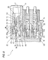
- Fig. 8 is a view explanatory of the operation at the time of canceling a fitted condition.
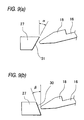
- Fig. 9 is a view showing a slanting surface of a retaining portion in Fig. 1.
- Fig. 10 is an exploded, perspective view showing one example of a general connector fitting structure.
- Fig. 11 is a view explanatory of an operation, showing a condition in which a fitting operation in Fig. 10 is started.
- Fig. 12 is a view explanatory of the operation, showing the process of the fitting operation in Fig. 10.
- Fig. 13 is a view explanatory of the operation, showing a condition in which the fitting operation in Fig. 10 is finished.
- Fig. 14 is a view explanatory of the operation at the time of canceling a fitted condition.
- A preferred embodiment of a connector fitting structure of the present invention will now be described in detail with reference to Figs. 1 to 8. Fig. 1 is a vertical cross-sectional view showing one preferred embodiment of the connector fitting structure of the invention, Fig. 2 is an exploded, perspective view of a slider in Fig. 1, Fig. 3 is a perspective view showing female and male connector housings in Fig. 1, Fig. 4 is a view explanatory of an operation, showing a condition in which a fitting operation in Fig. 1 is started, Fig. 5 is a view explanatory of the operation, showing the process of the fitting operation in Fig. 1, Fig. 6 is a view explanatory of the operation, showing a condition in which the fitting operation in Fig. 1 is further continued, Fig. 7 is a view explanatory of the operation, showing a condition in which the fitting operation in Fig. 1 is finished, Fig. 8 is a view explanatory of the operation at the time of canceling a fitted condition in Fig. 1, and Fig. 9 is a view showing a slanting surface of a retaining portion in Fig. 1.
- As shown in Figs. 1 to 3, The connector
fitting structure 1 includes a pair of female and male connectors to be fittingly connected together The male connector (one connector) 10 includes: aninner housing 12, which hassocket contacts 14 fitted therein, and is open to the front side thereof; and anouter housing 11 of a hood-like shape which has theslider 20 slidably mounted therein above theinner housing 12, and covers theinner housing 12. - Elastic lock
arms 16 are provided on an upper surface of theinner housing 12, and extend in a fitting direction of arrow F. Theelastic lock arm 16 have hook-like housing locks 18 formed respectively at front ends thereof. Apressing portion 19, which is operated when canceling the fitting connection, is provided on an upper surface of thelock arms 16 at a generally central portion thereof. - More specifically, a
slider receiving portion 13 is formed between the upper surface of theinner housing 12 and an inner surface of an upper wall of theouter housing 11.Guide grooves 15 for respectively guiding opposite side portions of theslider 20 are formed respectively in inner surfaces of opposite side walls of theouter housing 11. - A
side space 13a for receiving theslider 20 is formed between each of thelock arms 16 and the inner surface of each of the opposite side walls of theouter housing 11. Aninsertion space 16a is formed between thelock arms 16 and between the housing locks 18. Aseal member 12a (see Fig. 4) is fitted on the outer periphery of theinner housing 12. -
First engagement portions 46 for being engaged respectively with first engagement arms 28 (described later) are formed on the inner surface of the upper wall of theouter housing 11, and asecond engagement portion 48 for engagement with a second engagement arm 47 (described later) is formed on theouter housing 11. - The
slider 20 includes: afirst slide member 21, which is slidable within theouter housing 11 in the axial direction; asecond slide member 26, engaged with a rear portion of thefirst slide member 21; and compression springs (serving as resilient members) 33 which are held in thesecond slide member 26, and resiliently urge the first andsecond slide members - The
first slide member 21 includes: a pair ofstopper arm portions portion 24 interconnecting thestopper arm portions 23 at front ends thereof. Anabutment portion 25, against which a pressing rib 42 (described later) of thefemale connector 40 can abut, is formed at a lower surface of the interconnectingportion 24 at a front end portion thereof. Auxiliary retaining surfaces 23a for respectively retaining auxiliary retaining arms 49 (described later) are formed on upper surfaces of thestopper arm portions 23, respectively. - A
slide groove 22 is formed in the rear end of the interconnectingportion 24, and thisslide groove 22 allows the distal ends of the first engagement arms 28 (described later) to escape thereinto when the first andsecond slide members - Retaining
portions 27 for preventing the downward displacement of thehousing locks 18 are formed at the front end portion of thesecond slide member 26. Adisengagement prevention portion 29, which is operated when canceling the fitting connection, is formed on the upper surface of thesecond slide member 26 at a central portion thereof. When theslider 20 is mounted in theouter housing 11, thesecond slide member 26 covers thepressing portion 19. Anotch 27a is formed between the pair of retainingportions female connector 40 will not interfere with the second slide member when fitting the male andfemale connectors - A
cancellation projection 50 is formed on a lower surface of thedisengagement prevention portion 29 at a front end thereof, and when thesecond slide member 26 is moved forward during the cancellation of the fitting connection, thiscancellation projection 50 is abutted against thepressing portion 19 of thelock arms 16 to flex thelock arms 16 downwardly so as to cancel the engaged condition of the housing locks 18. - The
second slide member 26 has the pair of flat plate-like, elasticauxiliary retaining arms 49 each having anauxiliary retaining projection 49a formed on a lower surface thereof at a front end thereof. Theseprojections 49a can be retained by the auxiliary retaining surfaces 23a of thefirst slide member 21, respectively. A slantingsurface 30, which is slanting downwardly rearwardly and has an inclination angle β, is formed on a rear surface of each of the retaining portions 27 (see Fig. 9). - The
second slide member 26 further includes the pair offirst engagement arms 28 of an elastic nature, and thesecond engagement arm 47 of an elastic nature. Each of thefirst engagement arms 28 has at its front end afirst retaining projections 28a of a hook-like shape for engagement with the associatedfirst engagement portion 46 formed on the inner surface of the upper wall of theouter housing 11. Thesecond engagement arm 47 has at its front end asecond retaining projection 47a of a hook-like shape for engagement with thesecond engagement portion 48 formed on theouter housing 11. -
Pin contacts 45 project into the fitting direction of opposite to arrow F, from the interior of thehousing 41 of the female connector (the other connector) 40. Thepressing rib 42 for abutment against theabutment portion 25 of thefirst slide member 21 is formed on an upper wall of thehousing 41 at a widthwise central portion thereof, and extends in the fitting direction. A pair ofengagement projections 43 are formed respectively at opposite side portions of thepressing rib 42 at a front end of thee female connecctor, and theseengagement projections 43 elastically deform thelock arms 16, respectively, and engage thehousing locks 18, respectively. - Next, the fitting operation of the connector
fitting structure 1 of the above construction will be described. First, as shown in Fig. 2, the compression springs 33 are set at the opposite side portions of thesecond slide member 26, respectively, and then when thestopper arm portions 23 of thefirst slide member 21 are pressed against the compression springs, respectively, so that theauxiliary retaining projections 49a of the auxiliary retainingarms 49 are retained by theauxiliary retaining surfaces 23a, respectively, thus completing the assembling of theslider 20. - Then, as shown in Fig. 3, the
slider 20 is inserted into theslider receiving portion 13 along theguide grooves 15 in theouter housing 11 until the front end surface of the interconnectingportion 24 of theslider 20 becomes flush with the front end of the outer housing. As a result, thefirst retaining projections 28a of thefirst engagement arms 28 of thesecond slide member 26 are retained by thefirst engagement portions 46 of theouter housing 11, respectively, and also thesecond retaining projection 47a of thesecond engagement arm 47 is retained by thesecond engagement portion 48, as shown in Fig. 1. - Therefore, the
second slide member 26 is retained relative to theouter housing 11 of themale connector 10 at three portions (that is, the pair offirst engagement arms 28 and the second engagement arm 47), and therefore the first andsecond engagement arms second engagement portions outer housing 11, respectively, and therefore the slider will not be moved rearward. - Then, when the
housing 41 of thefemale connector 40 is inserted into themale connector 10 while the inner peripheral surface of thehousing 41 is guided by the outer periphery of theinner housing 12 of themale connector 10, the front end of thepressing rib 42 abuts against theabutment portion 25 of thefirst slide member 21, and also the retainingportions 27 of thesecond slide member 26 are brought into sliding contact with the upper surface of thehousing 41, as shown in Fig. 4. - Then, when the fitting operation further proceeds as shown in Fig. 5, only the
first slide member 21 is pushed by thepressing rib 42 of thefemale connector 40 against the repulsive force of the compression springs 33, with thesecond slide member 26 held in its position. Therefore, thefirst slide member 21, while compressing the compression springs 33, is moved toward the rear end of theslider receiving portion 13. As a result, theengagement projections 43 depress thehousing locks 18, respectively, so that thelock arms 16 are flexed downwardly. - Then, when the fitting operation further proceeds as shown in Fig. 6, the
first engagement arms 28 are disengaged from thefirst engagement portions 46, respectively, and thefirst engagement arm 28 are introduced into theslide groove 22 in an escaping manner, and also thesecond engagement arm 47 is pressed by the front end of thehousing 41 of thefemale connector 40 to be disengaged from thesecond engagement portion 48. Under the influence of the compression springs 33, the slanting surfaces 30 of the retainingportions 27 press the front ends of thehousing locks 18 rearwardly, respectively. - At this stage, if the fitting force, applied to the
female connector 40, is released, thefemale connector 40 is pushed back in a disengaging direction through theabutment portion 25 and thepressing rib 42 since thefirst slide member 21 is urged forward by the resilient forces of the compression springs 33. And besides, when the connector-fitting operation is not yet completed, thepressing portion 19 on thelock arms 16 is generally covered by thedisengagement prevention portion 29 of thesecond slide member 26. Therefore, such an incompletely-fitted condition can also be detected with the eyes. - Then, when the
female connector 40 is further pushed in the fitting direction as shown in Fig. 7, the downwardly-flexedlock arms 16 are restored into their original position, so that thehousing locks 18 are engaged with theengagement projections 43, respectively. As a result, the retainingportions 27 are disengaged from thehousing locks 18, respectively, therefore, thesecond slide member 26 is moved toward the rear end of themale connector 10 by the resilient forces of the compression springs 33. At this time, the retainingportions 27 are moved to be disposed under thehousing locks 18, respectively, so that thehousing locks 18 are kept engaged respectively with theengagement projections 43 in a locked manner, thus preventing the flexing of the lock arms. - Therefore, the male and
female connectors disengagement prevention portion 29 of thesecond slide member 26 is spaced rearwardly from thepressing portion 19 on thelock arms 16, and therefore the completely-fitted condition can be detected with the eyes. Also, the completely-fitted condition can be detected through the sense of touch when the resilient forces of the compression springs 33 are abruptly reduced. - Next, the fitting connection-canceling operation of the connector
fitting structure 1 of the above construction will be described. - In the completely-fitted condition of the male and
female connectors disengagement prevention portion 29 of thesecond slide member 26 is pushed forward with the finger or other against the repulsive force of the compression springs 33, thefirst engagement arms 28 abut against thefirst engagement portions 46, respectively, to be pressed down. Therefore escape into theslide groove 22 in thefirst slide member 21, as shown in Fig. 8. At this time, thecancellation projection 50, formed on the lower surface of thedisengagement prevention portion 29 at the front end thereof, abuts against thepressing portion 19 on thelock arms 16. Then, when thesecond slide member 26 is further pushed forward, the retainingportions 27 of thesecond slide member 26 are moved forward beyond thehousing locks 18, respectively, thus canceling the locked condition, so that thelock arms 16 are flexed downwardly. As a result of this flexing, the engagement of eachhousing lock 18 with the associatedengagement projection 43 is canceled, and themale connector 10 and thefemale connector 40 are moved from each other by the resilient force of the compression springs 33. - If the rear end surface of each retaining
portion 27 is vertical, or is slanting downwardly forwardly at an inclination angle α° as shown in Fig. 9A, the downwardly-flexedlock arm 16 can not be restored by its own restoring force, and hence can not be brought into engagement with theengagement projection 43 since the rear end surface presses the front end of thehousing lock 18 by the resilient force of thecompression spring 33. - When the slanting
surface 30, which is slanting downwardly rearwardly at an inclination angle β° as shown in Fig. 9B, is formed at the rear end surface of each retainingportion 27, the downwardly-flexedlock arm 16 is restored upwardly along this slantingsurface 30, and is engaged with theengagement projection 43, and therefore the fitting operation can be carried out with a low fitting force. - As described above, in the connector fitting structure of this embodiment, there are provided the
first engagement arms 28, for engagement respectively with thefirst engagement portions 46 formed on the inner surface of theouter housing 1 of themale connector 10, and thefirst engagement arm 28 have thefirst retaining projections 28a formed respectively at the front ends thereof. With this construction, thehousing 41 of the female connector 4 0 is fitted into themale connector 10, and theengagement projections 43 depress thehousing locks 18, respectively, and thereafter unless thefirst engagement arms 28 are caused to escape into theslide groove 22, thefirst engagement arms 28 will not be disengaged from thefirst engagement portions 46, respectively. - Therefore, before the
housing locks 18 are pressed down, thesecond slide member 26 will not be brought out of retaining engagement with theouter housing 11 by vibrations and so on, and hence thesecond slide member 26 will not be moved toward the rear end of the housing, and therefore the operation for mutually fitting the male andfemale connectors female connectors - As described above, in the connector fitting structure of this embodiment, the
housing 41 of thefemale connector 40 is fitted into themale connector 10, and theengagement projections 43 depress thehousing locks 18, respectively, Then thefirst engagement arms 28 are caused to escape into theslide groove 22, and therefore thefirst engagement arms 28 are disengaged from thefirst engagement portions 46, respectively. - At this time, the
second engagement arm 47 is pressed by the front end of thehousing 41 of thefemale connector 40 to be disengaged from thesecond engagement portion 48, and therefore the downwardly-flexedlock arms 16 are restored into their original position, so that thehousing locks 18 are engaged respectively with theengagement projections 43, thus achieving the completely-fitted condition. - For canceling the fitted condition of the male and
female connectors disengagement prevention portion 29 of thesecond slide member 26 is pushed forward, so that thefirst engagement arms 28 are caused to escape into theslide groove 22 in thefirst slide member 21, and also thecancellation projection 50 abuts against thepressing portion 19. Then, when thesecond slide member 26 is further pushed forward, thelock arms 16 are flexed downwardly, so that the engagement of eachhousing lock 18 with the associatedengagement projection 43 is canceled. Therefore themale connector 10 and thefemale connector 40 are easily moved away from each other by the resilient force of the compression springs 33. - Therefore, when canceling the fitted condition, it is only necessary to push the second slide member forward with a relatively-small pushing force, and therefore the canceling operation is easy, and the efficiency of the operation can be enhanced, and besides the lock arms will not be excessively displaced, and hence will not be damaged, thus enhancing the durability of the female and male connectors.
- The
second slide member 26 includes thesecond engagement arm 47 having thesecond retaining projection 47a formed at the front end thereof, and thesecond engagement portion 48 is formed on theinner housing 11 of themale connector 10. Therefore, until thesecond engagement arm 47 is disengaged from thesecond engagement portion 48 by the front end of thehousing 41 of thefemale connector 40, that is, until the time immediately before thehousing locks 18 are engaged respectively with theengagement projections 43 of thefemale connector 40, thesecond slide member 26 will not be disengaged from theouter housing 11 by vibrations and so on, and hence thesecond slide member 26 will not move toward the rear end of the housing. - Therefore, the compression springs 33 are kept compressed until the time immediately before the completely-fitted condition is achieved, and therefore the resilient force of these compression springs are kept strong, and if the fitting force is weakened in a half-fitted condition, the
female connector 40 can be positively pushed back in the disengaging direction, and therefore the reliability of the male andfemale connectors - And besides, the slanting
surface 30, which is slanting downwardly rearwardly at an inclination angle β°, is formed at the rear end surface of each of the retainingportions 27 of thesecond slide member 26, and therefore immediately before the male andfemale connectors housing lock 18 is returned to smoothly slide upwardly over the slantingsurface 30, with the resilient force of the compression springs 33 acting on thehousing lock 18, and is engaged with theengagement projection 43 of thefemale connector 40. Therefore, the male andfemale connectors male connectors - The present invention is not limited to the above embodiment, but can be applied to various embodiments. For example, in this embodiment, although the
slider 20 is received in themale connector 10, the slider can be received in thefemale connector 40. - Although there are provided the pair of
lock arms 16 and the pair offirst engagement arms 28, there may be provided one lock arm and one first engagement arm. The number of thesecond engagement arm 47 is not limited to one, but a pair of second engagement arms may be provided. - As described above, in the connector fitting structure of the above construction, the second slide member includes the elastic first engagement arms, which can be engaged respectively with the first engagement portions formed on the inner surface of the outer housing of the one connector, and the elastic second engagement arm which can be engaged with the second engagement portion formed on the outer housing. The first slide member has the slide groove which cancels the engaged condition of the first engagement arms, and also allows the first engagement arms to escape into the slide groove when the first and second slide members move toward each other against the resilient force of the resilient members during the fitting operation of the female and male connectors. The engaged condition of the second engagement arm of the second slide member is canceled by the front end of the housing of the other connector.
- Therefore, the housing of the other connector is fitted in the one connector, and thereafter unless the first engagement arms are caused to escape into the slide groove, the first engagement arms will not be disengaged from the first engagement portions, respectively. Therefore, there will not be encountered a situation in which the fitting operation of the female and male connectors can not be effected, and therefore the reliability of the female and male connectors can be enhanced.
- Until the second engagement arm is disengaged from the second engagement portion by the front end of the housing of the other connector, that is, until the time immediately before the housing locks are engaged respectively with the engagement projections of the other connector, the second slide member will not be disengaged from the outer housing by vibrations and so on, and hence the second slide member will not move toward the rear end of the housing.
- Therefore, if the fitting force is weakened in a half-fitted condition before the completely-fitted condition is achieved, the female and male connectors can be positively pushed back away from each other by the resilient force of the resilient members. Therefore, the reliability of the male and female connectors can be further enhanced.
- In the above connector fitting structure, preferably, the second slide member has the retaining portions which are formed at the front end thereof, and can prevent the downward displacement of the housing locks, and the slanting surface, which is slanting downwardly rearwardly, is formed on the rear end surface of each of the retaining portions. With this construction, immediately before the male and female connectors are completely fitted together, each housing lock is returned to smoothly slide upwardly over the slanting surface on the rear end surface of the retaining portion, and is engaged with the other connector. Therefore, the fitting operation of the male and female connectors can be carried out with the low insertion force, and also the female and male connectors can be positively completely fitted together, and therefore the reliability of the female and male connectors can be further enhanced.
- In the above connector fitting structure, preferably, the second slide member includes the flat plate-like auxiliary retaining arms which can be retained respectively by the auxiliary retaining surfaces of the first slide member. With this construction, the second slide member can be engaged with the first slide member in a stable manner, and is positively prevented from being disengaged from the first slide member by vibrations and so on, and the reliability of the slider can be enhanced.
- As described above, in the connector fitting structure of the invention, the cancellation projection is formed on the lower surface of the front end of the disengagement prevention portion which is operated when canceling the fitting connection, and when the second slide member is moved forward for canceling the fitting connection, the cancellation projection is abutted against the pressing portion on the lock arms to flex the lock arms, thereby canceling the engagement of the housing locks of the one connector with the respective engagement projections of the other connector.
- Therefore, when canceling the fitted condition of the female and male connectors, it is only necessary to push the second slide member forward, and therefore the operation, required for canceling the fitted condition, is easy, and the efficiency of the operation can be enhanced.
- And besides, the amount of flexing of the lock arms is determined by the vertical dimensions of the cancellation projection and pressing portion, and therefore the lock arms will not be excessively displaced, and hence will not be damaged, and the reliability and durability of the female and male connector can be enhanced.
- In the connector fitting structure, preferably, the second slide member has the first engagement arms engageable respectively with the first engagement portions formed on the inner surface of the outer housing, and when the second slide member is moved forward for canceling the fitting connection, the first engagement arms are caused to escape into the slide groove formed in the first slide member.
- Therefore, the engagement of the housing locks of the lock arms with the respective engagement projections of the other connector can be canceled with a relatively-small pushing force. Therefore, the efficiency of the operation, required for canceling the fitted condition of the female and male connectors, can be further enhanced.
Claims (21)
- A connector fitting structure comprising:a pair of female and male connectors to be connected together;one of said connector including an inner housing and an outer housing, said outer housing covering said inner housing, a lock arm provided on the front end of said inner housing;a slide member movably mounted on said outer housing, said slide member including first and second slide members, and a resilient member, said first slide member slidable with respect to said outer housing in fitting direction, said second slide member engaged with a rear end of said first slide member, said resilient member positioned between said first and second slide members to urge said first and second slide members away from each other;the other of said connector provided with a pressing rib which abuts against said slide member, an engagement projection, which flexes said lock arm and engages with said lock arm, provided on said pressing rib;a first elastically engagement arm provided at said second slide member, engageable with a first engagement portion which is provided at an inner surface of said outer housing;a slide groove provided at said first slide member; andwherein said slide groove cancels the engaged condition of said first engagement arm and said first engagement portion at when said first slide member is moved toward said second slide member.
- A connector fitting structure according to claim 1 further comprising, a second elastically engagement arm provided at said second slide member, engageable with a second engagement portion which is provided at an upper surface of said inner housing.
- A connector fitting structure according to claim 2, wherein a distal end of the other connector housing cancels the engaged condition of said second engagement arm and said second engagement portion at a time of said first slide member moving toward said second slide member.
- A connector fitting structure according to claim 1, wherein a retaining portion, for preventing a downward displacement of said lock arm, is provided at the front end of said second slide member.
- A connector fitting structure according to claim 4, wherein a slanting surface is formed at a rear end of said retaining portion.
- A connector fitting structure according to claim 1 further comprising:an auxiliary retaining surface provided at said first slide member;an auxiliary retaining arm provided at said second slide arm; andwherein said auxiliary retaining arm is retained by an auxiliary retaining surface.
- A connector fitting structure according to claim 6, wherein said auxiliary retaining arm formed in flat plate.
- A connector fitting structure according to claim 1, wherein an opening of said slide groove faces to said second slide member.
- A connector housing structure comprising:a pair of connector housing having respectively engagement portions to be engaged with each other for connection between housings;a slider for inhibiting one of said engagement portions from being disengaged from the other of said engagement portions, said slider having a first slide member, a second slide member movable toward and away from said first slide member, and an engagement arm engaged with one of said housings;wherein a relative movement between said first and second slide member in association with said connection between said housings disengages said engagement arm from said one of said housings.
- A connector fitting structure according to claim 9 further comprising:
a resilient member provided between said first and second slide member to urge said first and second slide members away from each other. - A connector fitting structure according to claim 9, wherein said engagement portion of said one of housing forms a lock arm, said engagement portion of the other of housing forms an engagement projection for engaging with said lock arm.
- A connector fitting structure comprising:a pair of female and male connectors to be connected together;one of said connector including an inner housing and an outer housing, said outer housing covering said inner housing, a lock arm provided on the front end of said inner housing;a slide member movably mounted on said outer housing, said slide member including first and second slide member, and a resilient member, said first slide member slidable with respect to said outer housing in fitting direction, said second slide member engaged with the rear end of said first slide member, said resilient member positioned between said first and second slide members to urge said first and second slide members away from each other;the other of said connector provided with a pressing rib which abuts against said slide member, and an engagement projection, which flexes said lock arm and engages with said lock arm, provided on said pressing rib; anda disengagement prevention portion provided at upper said second slide member, for canceling a engagement with said lock arm and said engagement projection;wherein said engagement is canceled by which said lock arm is deformed downwardly by abutting against said disengagement prevention portion when said second slide member is slid toward said fitting direction.
- A connector fitting structure according to claim 12, wherein the abutting position of said disengagement prevention portion is defined by a canceling projection projecting from the front end of the lower surface of said disengagement prevention portion.
- A connector fitting structure according to claim 12, wherein the abutting position of said lock arm is defined by a pressing portion projecting from said upper portion of said lock arm.
- A connector fitting structure according to claim 12, further comprising:a engagement arm provided at said second slide member, and engageable with a engagement portion which is provided at the inner surface of said outer housing; anda slide groove provided at said first slide member;wherein said engagement arm is accommodated in said slide groove by moving said second slide member forward at the time of canceling said engagement.
- A connector fitting structure according to claim 15, wherein an opening of said slide groove faces to said second slide member.
- A connector fitting structure comprising:a pair of connector having respectively engagement portions to be engaged with each other for connection between said housings;a slider for inhibiting one of said engagement portions from being disengaged from the other of said engagement portions when said housings are connected together, said slider being movably mounted on one of said housings, and having a canceling projection;wherein said canceling projection cancels said connection between said housings when said slider is slid along said one of said housings.
- A connector fitting structure according to claim 17, wherein said slider has first slide member and second slide member movable toward and away from said first slide member, said canceling portion is provided on said second slide member.
- A connector fitting structure according to claim 18 further comprising:
a resilient member provided between said first and second slide member to urge said first and second slide members away from each other. - A connector fitting structure according to claim 18, wherein said engagement portion of said one housing forms a lock arm, said engagement portion of the other housing forms an engagement projection for engaging with said lock arm, and said canceling projection abuts against said lock arm when said canceling projection cancels said connection.
- A connector substantially as described with reference to Figures 1 to 8 of the accompanying drawings.
Priority Applications (1)
| Application Number | Priority Date | Filing Date | Title |
|---|---|---|---|
| EP06127374.4A EP1768218B1 (en) | 1999-04-28 | 2000-04-20 | Connector fitting structure |
Applications Claiming Priority (4)
| Application Number | Priority Date | Filing Date | Title |
|---|---|---|---|
| JP12261099 | 1999-04-28 | ||
| JP12261099A JP3726999B2 (en) | 1999-04-28 | 1999-04-28 | Connector mating structure |
| JP12739899 | 1999-05-07 | ||
| JP12739899A JP4166903B2 (en) | 1999-05-07 | 1999-05-07 | Connector mating structure |
Related Child Applications (1)
| Application Number | Title | Priority Date | Filing Date |
|---|---|---|---|
| EP06127374.4A Division EP1768218B1 (en) | 1999-04-28 | 2000-04-20 | Connector fitting structure |
Publications (2)
| Publication Number | Publication Date |
|---|---|
| EP1049213A1 true EP1049213A1 (en) | 2000-11-02 |
| EP1049213B1 EP1049213B1 (en) | 2007-12-05 |
Family
ID=26459706
Family Applications (2)
| Application Number | Title | Priority Date | Filing Date |
|---|---|---|---|
| EP00303381A Expired - Lifetime EP1049213B1 (en) | 1999-04-28 | 2000-04-20 | Connector fitting structure |
| EP06127374.4A Expired - Lifetime EP1768218B1 (en) | 1999-04-28 | 2000-04-20 | Connector fitting structure |
Family Applications After (1)
| Application Number | Title | Priority Date | Filing Date |
|---|---|---|---|
| EP06127374.4A Expired - Lifetime EP1768218B1 (en) | 1999-04-28 | 2000-04-20 | Connector fitting structure |
Country Status (3)
| Country | Link |
|---|---|
| US (2) | US6475014B2 (en) |
| EP (2) | EP1049213B1 (en) |
| DE (1) | DE60037292T2 (en) |
Cited By (9)
| Publication number | Priority date | Publication date | Assignee | Title |
|---|---|---|---|---|
| EP1087470A2 (en) * | 1999-09-22 | 2001-03-28 | Sumitomo Wiring Systems, Ltd. | A connector |
| EP1237232A2 (en) * | 2001-03-02 | 2002-09-04 | Fci | Connector with a housing lock |
| DE10159757A1 (en) * | 2001-08-22 | 2003-03-13 | Sumitomo Wiring Systems | Interconnects |
| DE10346914B4 (en) * | 2002-10-10 | 2008-04-24 | Sumitomo Wiring Systems, Ltd., Yokkaichi | Connector and connector assembly |
| EP3190667A1 (en) * | 2016-01-05 | 2017-07-12 | Japan Aviation Electronics Industry, Ltd. | Connector and connector assembly |
| CN107093817A (en) * | 2017-05-04 | 2017-08-25 | 石狮市川朗机械设计有限公司 | A kind of convenient construction equipment |
| EP3214705A1 (en) * | 2016-03-03 | 2017-09-06 | Dai-Ichi Seiko Co., Ltd. | Connector |
| CN107293903A (en) * | 2017-05-04 | 2017-10-24 | 石狮市川朗机械设计有限公司 | A kind of modified construction equipment |
| CN108879211A (en) * | 2018-06-29 | 2018-11-23 | 安徽江淮汽车集团股份有限公司 | Automotive wire bundle plug-in unit |
Families Citing this family (28)
| Publication number | Priority date | Publication date | Assignee | Title |
|---|---|---|---|---|
| DE60218623T2 (en) * | 2002-01-30 | 2007-11-22 | Sumitomo Wiring Systems, Ltd., Yokkaichi | Interconnects |
| US6592390B1 (en) * | 2002-04-30 | 2003-07-15 | Tyco Electronics Corporation | HMZD cable connector latch assembly |
| JP2004079483A (en) * | 2002-08-22 | 2004-03-11 | Sumitomo Wiring Syst Ltd | Connector |
| US6857892B2 (en) * | 2003-06-05 | 2005-02-22 | Fci Americas Technology, Inc. | Electrical connector with connector position assurance member |
| US6827609B1 (en) * | 2003-11-12 | 2004-12-07 | Tyco Electronics Corporation | Electrical connector having improved terminal positioning assurance member |
| JP2006031965A (en) * | 2004-07-12 | 2006-02-02 | Yazaki Corp | Locking structure of connector |
| JP2006252806A (en) * | 2005-03-08 | 2006-09-21 | Tyco Electronics Amp Kk | Electric connector |
| JP4419875B2 (en) * | 2005-03-14 | 2010-02-24 | 住友電装株式会社 | Mating detection connector |
| US7131854B1 (en) * | 2005-08-31 | 2006-11-07 | Lear Corporation | Electrical connector and airbag apparatus having an electrical connector |
| JP4500245B2 (en) * | 2005-10-27 | 2010-07-14 | 矢崎総業株式会社 | connector |
| US7322846B2 (en) * | 2005-11-04 | 2008-01-29 | Winchester Electronics Corporation | Quick connect connector |
| JP2007335328A (en) * | 2006-06-16 | 2007-12-27 | Sumitomo Wiring Syst Ltd | Fitting member |
| US7232329B1 (en) * | 2006-07-05 | 2007-06-19 | Hon Hai Precision Ind. Co., Ltd. | Cable connector assembly with unitary latch |
| JP4669826B2 (en) * | 2006-08-23 | 2011-04-13 | 矢崎総業株式会社 | Connector unit |
| JP5211639B2 (en) * | 2007-10-29 | 2013-06-12 | 住友電装株式会社 | connector |
| US7637767B2 (en) * | 2008-01-04 | 2009-12-29 | Tyco Electronics Corporation | Cable connector assembly |
| JP5308761B2 (en) * | 2008-10-01 | 2013-10-09 | 矢崎総業株式会社 | connector |
| CN102187530B (en) * | 2008-10-15 | 2014-06-11 | Fci公司 | Latch assembly for a connector |
| JP5341477B2 (en) * | 2008-11-04 | 2013-11-13 | 矢崎総業株式会社 | connector |
| US8380724B2 (en) * | 2009-11-24 | 2013-02-19 | Microsoft Corporation | Grouping mechanism for multiple processor core execution |
| DE202011107900U1 (en) * | 2011-11-15 | 2011-11-28 | Rosenberger Hochfrequenztechnik Gmbh & Co. Kg | Connectors |
| US9525238B1 (en) * | 2016-01-13 | 2016-12-20 | Tyco Electronics Corporation | Low profile electrical connector |
| CN117080801A (en) | 2018-07-20 | 2023-11-17 | 富加宜(美国)有限责任公司 | High frequency connector with recoil |
| US11189953B2 (en) * | 2018-08-28 | 2021-11-30 | Aptiv Technologies Limited | Connector-assembly with primary-lock-reinforcement device |
| CN109586088B (en) * | 2018-11-29 | 2020-01-14 | 安徽江淮汽车集团股份有限公司 | Accurate car wiring harness plug-in components of joint |
| CN113258325A (en) | 2020-01-28 | 2021-08-13 | 富加宜(美国)有限责任公司 | High-frequency middle plate connector |
| JP7109872B2 (en) * | 2020-09-09 | 2022-08-01 | 矢崎総業株式会社 | Connector housing and wire harness |
| US11837806B2 (en) * | 2020-12-09 | 2023-12-05 | Lear Corporation | Grounding electrical connector |
Citations (4)
| Publication number | Priority date | Publication date | Assignee | Title |
|---|---|---|---|---|
| US4708413A (en) * | 1986-03-21 | 1987-11-24 | General Motors Corporation | Electrical connector with position assurance and assist |
| US5030127A (en) * | 1990-02-20 | 1991-07-09 | General Motors Corporation | Manually disengageable connector lock |
| US5425650A (en) * | 1993-02-01 | 1995-06-20 | Yazaki Corporation | Inclined engagement prevention structure for connector |
| EP0896396A2 (en) * | 1997-08-05 | 1999-02-10 | Sumitomo Wiring Systems, Ltd. | Fitting detecting connector |
Family Cites Families (1)
| Publication number | Priority date | Publication date | Assignee | Title |
|---|---|---|---|---|
| JP3468451B2 (en) * | 1997-09-09 | 2003-11-17 | 矢崎総業株式会社 | Connector mating structure |
-
2000
- 2000-04-20 EP EP00303381A patent/EP1049213B1/en not_active Expired - Lifetime
- 2000-04-20 DE DE60037292T patent/DE60037292T2/en not_active Expired - Lifetime
- 2000-04-20 EP EP06127374.4A patent/EP1768218B1/en not_active Expired - Lifetime
- 2000-04-21 US US09/556,822 patent/US6475014B2/en not_active Expired - Lifetime
-
2002
- 2002-05-03 US US10/137,315 patent/US6595793B2/en not_active Expired - Lifetime
Patent Citations (4)
| Publication number | Priority date | Publication date | Assignee | Title |
|---|---|---|---|---|
| US4708413A (en) * | 1986-03-21 | 1987-11-24 | General Motors Corporation | Electrical connector with position assurance and assist |
| US5030127A (en) * | 1990-02-20 | 1991-07-09 | General Motors Corporation | Manually disengageable connector lock |
| US5425650A (en) * | 1993-02-01 | 1995-06-20 | Yazaki Corporation | Inclined engagement prevention structure for connector |
| EP0896396A2 (en) * | 1997-08-05 | 1999-02-10 | Sumitomo Wiring Systems, Ltd. | Fitting detecting connector |
Cited By (17)
| Publication number | Priority date | Publication date | Assignee | Title |
|---|---|---|---|---|
| EP1087470A2 (en) * | 1999-09-22 | 2001-03-28 | Sumitomo Wiring Systems, Ltd. | A connector |
| EP1087470B1 (en) * | 1999-09-22 | 2008-11-19 | Sumitomo Wiring Systems, Ltd. | A connector |
| EP1237232A2 (en) * | 2001-03-02 | 2002-09-04 | Fci | Connector with a housing lock |
| EP1237232A3 (en) * | 2001-03-02 | 2003-11-26 | Fci | Connector with a housing lock |
| DE10159757A1 (en) * | 2001-08-22 | 2003-03-13 | Sumitomo Wiring Systems | Interconnects |
| DE10159757B4 (en) * | 2001-08-22 | 2004-04-01 | Sumitomo Wiring Systems, Ltd., Yokkaichi | Interconnects |
| US6722913B2 (en) | 2001-08-22 | 2004-04-20 | Sumitomo Wiring Systems, Ltd. | Connector |
| DE10346914B4 (en) * | 2002-10-10 | 2008-04-24 | Sumitomo Wiring Systems, Ltd., Yokkaichi | Connector and connector assembly |
| EP3190667A1 (en) * | 2016-01-05 | 2017-07-12 | Japan Aviation Electronics Industry, Ltd. | Connector and connector assembly |
| US9787023B2 (en) | 2016-01-05 | 2017-10-10 | Japan Aviation Electronics Industry, Limited | Connector and connector assembly with touch rotection feature |
| EP3214705A1 (en) * | 2016-03-03 | 2017-09-06 | Dai-Ichi Seiko Co., Ltd. | Connector |
| CN107154558A (en) * | 2016-03-03 | 2017-09-12 | 第精工株式会社 | Connector |
| US9935396B2 (en) | 2016-03-03 | 2018-04-03 | Dai-Ichi Seiko Co., Ltd. | Connector having first and second housings and a sliding member implementing a connector position assurance function |
| CN107093817A (en) * | 2017-05-04 | 2017-08-25 | 石狮市川朗机械设计有限公司 | A kind of convenient construction equipment |
| CN107293903A (en) * | 2017-05-04 | 2017-10-24 | 石狮市川朗机械设计有限公司 | A kind of modified construction equipment |
| CN108879211A (en) * | 2018-06-29 | 2018-11-23 | 安徽江淮汽车集团股份有限公司 | Automotive wire bundle plug-in unit |
| CN108879211B (en) * | 2018-06-29 | 2019-06-28 | 安徽江淮汽车集团股份有限公司 | Automotive wire bundle plug-in unit |
Also Published As
| Publication number | Publication date |
|---|---|
| DE60037292D1 (en) | 2008-01-17 |
| EP1768218A2 (en) | 2007-03-28 |
| US6475014B2 (en) | 2002-11-05 |
| EP1768218A3 (en) | 2007-07-04 |
| US20020132510A1 (en) | 2002-09-19 |
| US6595793B2 (en) | 2003-07-22 |
| EP1768218B1 (en) | 2014-03-05 |
| EP1049213B1 (en) | 2007-12-05 |
| US20010046814A1 (en) | 2001-11-29 |
| DE60037292T2 (en) | 2008-10-23 |
Similar Documents
| Publication | Publication Date | Title |
|---|---|---|
| EP1049213B1 (en) | Connector fitting structure | |
| US6494732B2 (en) | Connector fitting structure | |
| US6065991A (en) | Half-fitting prevention connector | |
| US6095843A (en) | Connector fitting construction | |
| US5820399A (en) | Connector fitting construction | |
| EP1176676B1 (en) | Connector fitting structure | |
| US6488524B2 (en) | Half-fitting prevention connector | |
| EP0993077B1 (en) | Half-fitting prevention connector and method of producing same | |
| US6027364A (en) | Connector fitting construction with side ribs and corresponding side rib-receiving portions | |
| JP3458034B2 (en) | Connector mating release mechanism | |
| GB2342791A (en) | Connector preventing half-fitting, having trapezoidal abutment | |
| US6171130B1 (en) | Half-fitting prevention connector | |
| US6527578B2 (en) | Connector fitting structure | |
| US6224414B1 (en) | Half-fitting prevention connector | |
| US20030186579A1 (en) | Connector and a connector assembly | |
| EP1081803B1 (en) | Half-fitting prevention connector | |
| US6247955B1 (en) | Half-fitting prevention connector | |
| JP3405894B2 (en) | Half mating prevention connector | |
| JP3285308B2 (en) | Half mating prevention connector | |
| JP3249739B2 (en) | Half mating prevention connector | |
| JP3726999B2 (en) | Connector mating structure | |
| JP4166903B2 (en) | Connector mating structure | |
| JPH10134890A (en) | Connector | |
| JPH08236208A (en) | Connector |
Legal Events
| Date | Code | Title | Description |
|---|---|---|---|
| PUAI | Public reference made under article 153(3) epc to a published international application that has entered the european phase |
Free format text: ORIGINAL CODE: 0009012 |
|
| AK | Designated contracting states |
Kind code of ref document: A1 Designated state(s): DE FR GB |
|
| AX | Request for extension of the european patent |
Free format text: AL;LT;LV;MK;RO;SI |
|
| 17P | Request for examination filed |
Effective date: 20010420 |
|
| AKX | Designation fees paid |
Free format text: DE FR GB |
|
| 17Q | First examination report despatched |
Effective date: 20060426 |
|
| RAP1 | Party data changed (applicant data changed or rights of an application transferred) |
Owner name: YAZAKI CORPORATION |
|
| GRAP | Despatch of communication of intention to grant a patent |
Free format text: ORIGINAL CODE: EPIDOSNIGR1 |
|
| GRAS | Grant fee paid |
Free format text: ORIGINAL CODE: EPIDOSNIGR3 |
|
| GRAA | (expected) grant |
Free format text: ORIGINAL CODE: 0009210 |
|
| AK | Designated contracting states |
Kind code of ref document: B1 Designated state(s): DE FR GB |
|
| REG | Reference to a national code |
Ref country code: GB Ref legal event code: FG4D |
|
| REF | Corresponds to: |
Ref document number: 60037292 Country of ref document: DE Date of ref document: 20080117 Kind code of ref document: P |
|
| ET | Fr: translation filed | ||
| PLBE | No opposition filed within time limit |
Free format text: ORIGINAL CODE: 0009261 |
|
| STAA | Information on the status of an ep patent application or granted ep patent |
Free format text: STATUS: NO OPPOSITION FILED WITHIN TIME LIMIT |
|
| 26N | No opposition filed |
Effective date: 20080908 |
|
| REG | Reference to a national code |
Ref country code: FR Ref legal event code: PLFP Year of fee payment: 17 |
|
| REG | Reference to a national code |
Ref country code: FR Ref legal event code: PLFP Year of fee payment: 18 |
|
| REG | Reference to a national code |
Ref country code: FR Ref legal event code: PLFP Year of fee payment: 19 |
|
| PGFP | Annual fee paid to national office [announced via postgrant information from national office to epo] |
Ref country code: FR Payment date: 20190313 Year of fee payment: 20 |
|
| PGFP | Annual fee paid to national office [announced via postgrant information from national office to epo] |
Ref country code: DE Payment date: 20190410 Year of fee payment: 20 |
|
| PGFP | Annual fee paid to national office [announced via postgrant information from national office to epo] |
Ref country code: GB Payment date: 20190417 Year of fee payment: 20 |
|
| REG | Reference to a national code |
Ref country code: DE Ref legal event code: R071 Ref document number: 60037292 Country of ref document: DE |
|
| REG | Reference to a national code |
Ref country code: GB Ref legal event code: PE20 Expiry date: 20200419 |
|
| PG25 | Lapsed in a contracting state [announced via postgrant information from national office to epo] |
Ref country code: GB Free format text: LAPSE BECAUSE OF EXPIRATION OF PROTECTION Effective date: 20200419 |