US6592390B1 - HMZD cable connector latch assembly - Google Patents
HMZD cable connector latch assembly Download PDFInfo
- Publication number
- US6592390B1 US6592390B1 US10/136,725 US13672502A US6592390B1 US 6592390 B1 US6592390 B1 US 6592390B1 US 13672502 A US13672502 A US 13672502A US 6592390 B1 US6592390 B1 US 6592390B1
- Authority
- US
- United States
- Prior art keywords
- arm
- moveable latch
- moveable
- latch
- electrical connector
- Prior art date
- Legal status (The legal status is an assumption and is not a legal conclusion. Google has not performed a legal analysis and makes no representation as to the accuracy of the status listed.)
- Expired - Lifetime
Links
Images


Classifications
-
- H—ELECTRICITY
- H01—ELECTRIC ELEMENTS
- H01R—ELECTRICALLY-CONDUCTIVE CONNECTIONS; STRUCTURAL ASSOCIATIONS OF A PLURALITY OF MUTUALLY-INSULATED ELECTRICAL CONNECTING ELEMENTS; COUPLING DEVICES; CURRENT COLLECTORS
- H01R13/00—Details of coupling devices of the kinds covered by groups H01R12/70 or H01R24/00 - H01R33/00
- H01R13/62—Means for facilitating engagement or disengagement of coupling parts or for holding them in engagement
- H01R13/627—Snap or like fastening
- H01R13/6275—Latching arms not integral with the housing
-
- H—ELECTRICITY
- H01—ELECTRIC ELEMENTS
- H01R—ELECTRICALLY-CONDUCTIVE CONNECTIONS; STRUCTURAL ASSOCIATIONS OF A PLURALITY OF MUTUALLY-INSULATED ELECTRICAL CONNECTING ELEMENTS; COUPLING DEVICES; CURRENT COLLECTORS
- H01R12/00—Structural associations of a plurality of mutually-insulated electrical connecting elements, specially adapted for printed circuits, e.g. printed circuit boards [PCB], flat or ribbon cables, or like generally planar structures, e.g. terminal strips, terminal blocks; Coupling devices specially adapted for printed circuits, flat or ribbon cables, or like generally planar structures; Terminals specially adapted for contact with, or insertion into, printed circuits, flat or ribbon cables, or like generally planar structures
- H01R12/70—Coupling devices
- H01R12/71—Coupling devices for rigid printing circuits or like structures
- H01R12/72—Coupling devices for rigid printing circuits or like structures coupling with the edge of the rigid printed circuits or like structures
- H01R12/722—Coupling devices for rigid printing circuits or like structures coupling with the edge of the rigid printed circuits or like structures coupling devices mounted on the edge of the printed circuits
- H01R12/724—Coupling devices for rigid printing circuits or like structures coupling with the edge of the rigid printed circuits or like structures coupling devices mounted on the edge of the printed circuits containing contact members forming a right angle
-
- H—ELECTRICITY
- H01—ELECTRIC ELEMENTS
- H01R—ELECTRICALLY-CONDUCTIVE CONNECTIONS; STRUCTURAL ASSOCIATIONS OF A PLURALITY OF MUTUALLY-INSULATED ELECTRICAL CONNECTING ELEMENTS; COUPLING DEVICES; CURRENT COLLECTORS
- H01R13/00—Details of coupling devices of the kinds covered by groups H01R12/70 or H01R24/00 - H01R33/00
- H01R13/46—Bases; Cases
- H01R13/514—Bases; Cases composed as a modular blocks or assembly, i.e. composed of co-operating parts provided with contact members or holding contact members between them
-
- H—ELECTRICITY
- H01—ELECTRIC ELEMENTS
- H01R—ELECTRICALLY-CONDUCTIVE CONNECTIONS; STRUCTURAL ASSOCIATIONS OF A PLURALITY OF MUTUALLY-INSULATED ELECTRICAL CONNECTING ELEMENTS; COUPLING DEVICES; CURRENT COLLECTORS
- H01R13/00—Details of coupling devices of the kinds covered by groups H01R12/70 or H01R24/00 - H01R33/00
- H01R13/646—Details of coupling devices of the kinds covered by groups H01R12/70 or H01R24/00 - H01R33/00 specially adapted for high-frequency, e.g. structures providing an impedance match or phase match
- H01R13/6461—Means for preventing cross-talk
- H01R13/6471—Means for preventing cross-talk by special arrangement of ground and signal conductors, e.g. GSGS [Ground-Signal-Ground-Signal]
-
- H—ELECTRICITY
- H01—ELECTRIC ELEMENTS
- H01R—ELECTRICALLY-CONDUCTIVE CONNECTIONS; STRUCTURAL ASSOCIATIONS OF A PLURALITY OF MUTUALLY-INSULATED ELECTRICAL CONNECTING ELEMENTS; COUPLING DEVICES; CURRENT COLLECTORS
- H01R13/00—Details of coupling devices of the kinds covered by groups H01R12/70 or H01R24/00 - H01R33/00
- H01R13/648—Protective earth or shield arrangements on coupling devices, e.g. anti-static shielding
- H01R13/658—High frequency shielding arrangements, e.g. against EMI [Electro-Magnetic Interference] or EMP [Electro-Magnetic Pulse]
- H01R13/6581—Shield structure
- H01R13/6585—Shielding material individually surrounding or interposed between mutually spaced contacts
- H01R13/6586—Shielding material individually surrounding or interposed between mutually spaced contacts for separating multiple connector modules
Definitions
- Certain embodiments of the present invention generally relate to an electrical connector assembly having a header connector mateable with a receptacle connector, and more particularly, to apparatus for fastening and unfastening cable connectors to and from one another.
- latching mechanisms typically include a projection on a first connector half that extends therefrom in a direction transverse to a mating direction along which the first connector half and a second connector half are mated.
- the second connector half typically includes a notch or hole for receiving the projection on the first connector half, or includes a wall or another projection for engaging with the projection on the first connector half.
- mechanical latch-releasing mechanisms for disengaging the latching mechanisms between the connector halves in order to facilitate unmating of the connector halves.
- latch-releasing mechanisms include a driving member, to be activated by a user, that causes the projection on the first connector half to move, thereby disengaging the projection from a notch, hole, wall, or projection on the second connector half.
- latch-releasing mechanisms that are disposed on opposite sides of the connectors. These latch-releasing mechanisms require pinching or squeezing on opposite sides of the connectors to release a locking mechanism such as a latch. Consequently, these connectors require access to the connectors from both sides thereof in order to release the latching mechanism.
- a connector has latches on opposite sides thereof and a U-shaped latch-releasing mechanism, accessible from the top of the connector.
- the latch-releasing mechanism can be pushed downward, causing the latches on the sides to release.
- the latch-releasing mechanism requires access only to the top of the connector and not to the sides of the connector.
- the latches on the sides and the latch-releasing mechanism on top thereby increase both the connector's width and height.
- connectors have ramped or chamfered surfaces for forcing locking means to flex or compact during mating and unmating of connector halves.
- the connector halves are simply pushed on to, and pulled off from, complimentary connector halves. Mating and unmating by the sheer application of force can damage the connector housings and the precisely arranged contacts within the housings as well as the connections between the connectors and printed circuit boards (PCBs).
- PCBs printed circuit boards
- An example of an environment wherein access to a pair of mated connector halves is very limited, is in the field of telecommunications cables.
- several cable connectors may be required to fit into a small box that also houses a back plane PCB and several daughter PCBs.
- the daughter PCBs may be arranged parallel to one another and only separated from one another by a small distance such as one inch. It may be required that the cable connectors be mounted to the daughter PCBs and positioned in the small distances between the daughter PCBs.
- the cable connectors may also be mounted side by side with one another in very close proximity or even abutting one another.
- An embodiment of the present invention provides a cable connector assembly with a locking mechanism.
- the locking mechanism includes a stationary arm on a first connector to which a moveable latch on a second connector is locked and unlocked.
- the first connector includes a moveable arm, or a plurality of moveable arms, for lifting the moveable latch on the second connector to disengage the stationary arm on the first connector.
- a driving member on the first connector drives the moveable arm from first to second positions, causing the moveable arm to lift the moveable latch.
- a first spring returns the moveable arm to the first position, while a second spring biases the moveable latch downward to return the moveable latch to a resting position after the moveable latch has been lifted.
- the moveable arm may be modified to offer flexible, slidable, or liftable motion.
- the moveable arm may have a chamfered or ramped surface that engages a complimentary ramped surface on the connector housing, thereby forcing the flexible arm to flex.
- the moveable arm may have a chamfered or ramped surface that engages and lifts the moveable latch directly.
- the moveable arm may constitute an end of a lever that lifts the moveable latch.
- the driving member may be configured to be slidable toward or away from the moveable latch, or, alternatively, it may be configured to be rotatable about an axis.
- FIG. 1 illustrates a top rear perspective view of a header assembly formed in accordance with an embodiment of the present invention.
- FIG. 2 illustrates a cross sectional view of the header assembly taken along line 2 — 2 in FIG. 1 .
- FIG. 3 illustrates a cross sectional view of the header assembly taken along line 3 — 3 in FIG. 1 .
- FIG. 4 illustrates a top rear perspective view of a receptacle assembly formed in accordance with an embodiment of the present invention.
- FIG. 5 illustrates a top rear perspective view of receptacle and header assemblies mated, but not locked, to one another.
- FIG. 6 illustrates an exploded view of a receptacle assembly formed in accordance with an alternative embodiment of the present invention.
- FIG. 7 illustrates a top rear perspective view of a receptacle assembly mated, and locked, with a header assembly formed in accordance with an embodiment of the present invention.
- FIG. 8 illustrates a top rear perspective view of the receptacle and header assemblies of FIG. 7 mated, but not locked, to one another.
- FIG. 9 illustrates a cross sectional view of the receptacle and header assemblies taken along line 9 — 9 in FIG. 7 .
- FIG. 10 illustrates a cross sectional view of portions of the receptacle and header assemblies taken along line 10 — 10 in FIG. 8 .
- FIG. 11 illustrates an exploded view of a receptacle assembly formed in accordance with an alternative embodiment of the present invention.
- FIG. 12 illustrates a top rear perspective view of a receptacle assembly mated, and locked, with a header assembly formed in accordance with an embodiment of the present invention.
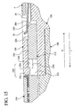
- FIG. 13 illustrates a top rear perspective view of the receptacle and header assemblies of FIG. 12 mated, but not locked, to one another.
- FIG. 14 illustrates a cross sectional view of the receptacle and header assemblies taken along line 14 — 14 in FIG. 12 .
- FIG. 15 illustrates a cross sectional view of portions of the receptacle and header assemblies taken along line 15 — 15 in FIG. 13 .
- FIG. 1 illustrates a right angle header assembly 2 formed in accordance with an embodiment of the present invention.
- the header assembly 2 includes a header housing 4 holding a plurality of signal modules 6 therein.
- the signal modules 6 are aligned adjacent to one another.
- the signal modules 6 include pins 7 for mating with vias on a back plane PCB (not shown).
- the header housing 4 includes top and bottom walls 8 and 10 , respectively, that are aligned parallel to, and spaced apart from, one another by a main wall 12 .
- the main wall 12 includes a signal module-mating surface 14 and a receptacle assembly-mating surface 16 opposite one another.
- the signal modules 6 are joined with the header housing 4 along the signal module-mating surface 14 .
- the signal modules 6 include signal pins 18 arranged in differential pairs 19 and L-shaped ground shields 20 protruding through the main wall 12 and extending beyond the receptacle assembly-mating surface 16 for mating with receptacle assemblies 44 , 90 , and 186 (FIGS. 4, 6 , and 11 ). Two of the ground shields 20 are partially cut away to reveal the signal pins 18 .
- the receptacle assembly-mating surface 16 and the top and bottom walls 8 and 10 define a space for receiving receptacle assemblies 44 , 90 , and 186 .
- the top and bottom walls 8 and 10 include edges 22 and rails 24 , respectively, for guiding the receptacle assemblies 44 , 90 , and 186 onto the header assembly 2 during mating.
- the main wall 12 includes a cantilever latch 26 proximate the top wall 8 .
- the cantilever latch 26 is formed from metal or another flexible material.
- the cantilever latch 26 includes a square window 28 for locking with a mated receptacle assembly 44 , 90 , and 186 .
- a rear edge 30 of the cantilever latch 26 is curved upward away from the bottom wall 10 .
- FIG. 2 illustrates a cross-sectional view of the header assembly 2 taken along line 2 — 2 in FIG. 1 .
- Each cantilever latch 26 includes a mounting blade 32 and a flexible body section 34 .
- the mounting blade 32 is flat and generally rectangular in shape.
- the mounting blade 32 is secured in a slot 36 formed in the main wall 12 .
- the flexible body section 34 is generally flat and rectangular in shape.
- the flexible body section 34 includes square cutout 38 and the square window 28 .
- the square cutout 38 includes a cantilever tab 40 .
- the cantilever latch 26 is loaded into the header assembly 2 in the direction of arrow A until the mounting blade 32 occupies the slot 36 .
- FIG. 3 illustrates a cross sectional view of a portion of the header assembly 2 taken along line 3 — 3 in FIG. 1 .
- the cantilever tab 40 of the cantilever latch 26 extends upward at an angle from the plane of the flexible body section 34 and toward a bottom surface 42 of the top wall 8 .
- the cantilever tab 40 is deflected rotatably downward in the direction of arrow B and into the square cutout 38 .
- the cantilever tab 40 biases rotatably upward to a locked position (shown in FIG. 3 ).
- the cantilever latch 26 may not move in the direction of arrow C because the cantilever tab 40 now engages the receptacle assembly-mating surface 16 .
- FIG. 4 illustrates a receptacle assembly 44 for mating with the header assembly 2 formed in accordance with an embodiment of the present invention.
- the receptacle assembly 44 includes front and rear housings 46 and 48 .
- the rear housing 48 optionally may comprise a plurality of signal modules 49 , which are illustrated by dashed lines 51 only in the example of FIG. 4 .
- the rear housing 48 includes a rear surface 50 having a plurality of cables 52 extending therefrom. In the example of FIG. 4, each cable 52 corresponds to two pins 18 and one ground shield 20 on the receptacle assembly-mating surface 16 of the header assembly 2 .
- the front housing 46 includes a header assembly-mating surface 54 opposite the rear surface 50 for mating with the header assembly 2 .
- a top surface 56 of the front housing 46 includes a locking arm 60 straddled on both sides by channels 62 .
- the locking arm 60 includes an upwardly projecting tooth 64 that has a front ramped surface 66 and a rear walled surface 68 .
- the top surface 56 also includes a latching member 58 for locking and unlocking with the cantilever latch 26 of the header assembly 2 .
- the latching member 58 includes a lever 70 rotatable about a pin 72 .
- the lever 70 includes an actuating end 74 and a working end 76 .
- the actuating end 74 includes a push surface 78 .
- the actuating end 74 includes a spring beam 80 and a stop rib 82 .
- a free end 84 of the spring beam 80 contacts a top surface 86 of the rear housing 48 .
- the working end 76 of the lever 70 includes a pair of forked fingers 88 that partially occupy the channels 62 for lifting the cantilever latch 26 on the header assembly 2 .
- FIG. 5 illustrates the header assembly 2 mated with, but not locked to, the receptacle assembly 44 .
- the header assembly 2 is capable of mating with two receptacle assemblies 44 , but only one receptacle assembly 44 is shown.
- the front ramped surface 66 of the tooth 64 engages and lifts the upwardly curved rear edge 30 of the cantilever latch 26 in the direction of arrow D, allowing the tooth 64 to pass under the cantilever latch 26 .
- the cantilever latch 26 recoils downward to a locked position (shown in FIG. 1 ).
- the tooth 64 projects upward through the square window 28 of the cantilever latch 26 . Unmating of the receptacle assembly 44 from the header assembly 2 is prohibited by interaction of the rear walled surface 68 of the tooth 64 and the square window 28 .
- FIG. 6 illustrates an exploded view of a receptacle assembly 90 for mating with the header assembly 2 formed in accordance with an alternative embodiment of the present invention.
- the receptacle assembly 90 includes front, rear, and pull housings 92 - 94 .
- the rear housing 93 includes a rear surface 96 having a plurality of cables 98 extending therefrom.
- each cable 98 corresponds to two pins 18 and one ground shield 20 on the receptacle assembly-mating surface 16 of the header assembly 2 .
- the front housing 92 includes a header assembly-mating surface 100 opposite the rear surface 96 for mating with the header assembly 2 .
- the front housing 92 includes a top surface 102 having rectangular windows 104 for manufacturing purposes formed therein.
- the front housing 92 includes rails 106 - 108 separated from one another by channels 110 and 112 .
- a center rail 107 includes an upwardly projecting tooth 116 .
- the tooth 116 has a front ramped surface 118 and a rear walled surface 120 .
- the pull housing 94 includes flexible arms 122 that extend through the front housing 92 and slidably rest in, and partially occupy, the channels 110 and 112 .
- the flexible arms 122 are positioned on either side of the center rail 107 .
- the pull housing 94 includes ribbed pull surfaces 124 along top and bottom surfaces 126 and 128 of the pull housing 94 .
- the pull housing 94 also includes a rear surface 130 having a spring-loading chamber 132 formed therein.
- the spring-loading chamber 132 in the rear end of the pull housing 94 receives a spring 140 that is inserted in the direction of arrow G.
- the spring 140 includes a front section 142 , a coil 144 , and a rear section 146 .
- the front section 142 is generally square in shape and includes side edges 148 having triangular projections 150 extending outward therefrom.
- the triangular projections 150 allow loading of the front section 142 into the front housing 92 in the direction of arrow G, and, thereafter, prevent rearward movement of the front section 142 in the direction of arrow H.
- the coil 144 connects the front section 142 to the rear section 146 , and is extendable in length so as to allow the front and rear sections 142 and 146 to move relative to one another. In FIG. 6, the coil 144 is shown in its resting state.
- the rear section 146 is rectangular in shape and has leading edges 152 .
- the pull housing 94 is loaded in the direction of arrow G into a rectangular chamber 154 in the rear end of the front housing 92 .
- the pull housing 94 includes a rectangular mating portion 156 that is inserted into the chamber 154 .
- the mating portion 156 includes a top surface 157 and includes sides 158 having triangular projections 160 extending therefrom.
- the triangular projections 160 allow loading of the mating portion 156 into the front housing 92 in the direction of arrow G and prevent removal of the mating portion 156 from the chamber 154 in the direction of arrow H beyond a predetermined action distance 182 (FIG. 9 ).
- the action distance 182 defines an operating range for the pull housing 94 .
- the flexible arms 122 which extend from the front of the mating portion 156 , include downwardly projecting ramps 162 for engaging upwardly projecting ramps 164 (more easily seen in FIG. 10) on the front housing 92 .
- FIG. 7 illustrates the receptacle assembly 90 mated with, and locked to, the header assembly 2 .
- the header assembly 2 is capable of mating with two receptacle assemblies 90 , but only one receptacle assembly 90 is shown.
- the front ramped surface 118 of the tooth 116 engages and lifts the upwardly curved rear edge 30 of the cantilever latch 26 , allowing the tooth 116 to pass under the cantilever latch 26 .
- the cantilever latch 26 recoils downward to a locked position (shown in FIG. 7 ).
- the tooth 116 projects upward through the square window 28 of the cantilever latch 26 .
- the front and pull housings 92 and 94 abut one another at interface 166 . Unmating of the receptacle assembly 90 from the header assembly 2 is prevented since the rear walled surface 120 of the tooth 116 is held within the square window 28 .
- FIG. 8 illustrates the header assembly 2 mated with the receptacle assembly 90 , but with the pull housing 94 pulled in the direction of arrow H.
- a rearward force applied by the user to the pull housing 94 in the direction of arrow H causes the front and pull housings 92 and 94 to become separated by a gap 168 .
- the pull housing 94 is located as shown in FIG. 8, the receptacle assembly 90 can be pulled free, in the direction of arrow H, from the header assembly 2 because the rear walled surface 120 of the tooth 116 no longer engages the square window 28 .
- FIG. 9 illustrates a cross-sectional view of the header assembly 2 mated with the receptacle assembly 90 taken along line 9 — 9 in FIG. 7 .
- the spring-loading chamber 132 includes rectangular sub-chambers 170 and 172 .
- the sub-chamber 170 has a width 174 that is greater than a width 176 of the sub-chamber 172 .
- the width 176 of the sub-chamber 172 is great enough to allow the loading of the front section 142 and the coil 144 , but not the rear section 146 , of the spring 140 .
- the spring 140 is loaded into the spring-loading chamber 132 until the leading edges 152 of the rear section 146 abut walls 178 at the rear of the sub-chamber 172 .
- the front section 142 of the spring 140 and the mating portion 156 of the pull housing 94 extend into the chamber 154 .
- the front section 142 lies on the top surface 157 of the mating portion 156 .
- the chamber 154 includes rear walls 180 for engaging the triangular projections 150 and 160 .
- the triangular projections 150 prevent the front section 142 of the spring 140 from moving in the direction of arrow H.
- the triangular projections 160 prevent the pull housing 94 from moving more than the distance 182 in the direction of arrow H.
- FIG. 10 illustrates a detailed cross-sectional view of the flexible arms 122 lifting the cantilever latch 26 taken along line 10 — 10 in FIG. 8 .
- the flexible arms 122 are flexed upward a distance 184 , thereby lifting the cantilever latch 26 over the tooth 116 and unlocking the receptacle assembly 90 from the header assembly 2 .
- the pull housing 94 pulls the flexible arms 122 rearward. Consequently, the ramps 162 on the flexible arms 122 slide rearward across the ramps 164 on the front housing 92 , causing the flexible arms 122 to flex upward in the direction of arrow I. As the flexible arms 122 flex upward, the flexible arms 122 lift the cantilever latch 26 above the tooth 116 . While the pull housing 94 pulls the flexible arms 122 rearward, the pull housing 94 also pulls the rear section 146 of the spring 140 rearward, thereby elongating the coil 144 . Once the rearward force on the pull housing 94 is removed, the coil 144 causes the pull housing 94 to recoil in the direction of arrow G to the locked position (shown in FIG. 7 ).
- FIG. 11 illustrates an exploded view of a receptacle assembly 186 for mating with the header assembly 2 formed in accordance with an alternative embodiment of the present invention.
- the receptacle assembly 186 includes front, rear, and push housings 188 - 190 .
- the rear housing 189 includes a rear surface 192 having a plurality of cables 194 extending therefrom.
- each cable 194 corresponds to two pins 18 and one ground shield 20 on the receptacle assembly-mating surface 16 of the header assembly 2 .
- the front housing 188 includes a header assembly-mating surface 196 opposite the rear surface 192 for mating with the header assembly 2 .
- the front housing 188 includes a top surface 198 having channels 200 and 202 formed therein.
- the channels 200 and 202 include a rail 204 therebetween.
- the rail 204 includes an upwardly projecting tooth 206 .
- the tooth 206 has a front ramped surface 208 and a rear walled surface 210 .
- the front housing 188 also includes a rear wall 211 having a rectangular chamber 213 formed therein.
- the push housing 190 includes a mating portion 212 for mating with the front housing 188 .
- the mating portion 212 includes a top surface 214 and a rectangular body section 216 .
- the body section 216 includes beams 218 - 220 that connect the body section 216 to the remainder of the push housing 190 .
- the beams 218 - 220 are separated from one another by channels 222 and 224 .
- the body section 216 includes beams 226 and 228 extending therefrom.
- the beams 226 and 228 include chamfered ends 230 for lifting the cantilever latch 26 on the header assembly 2 .
- the push housing 190 also includes a spring-loading chamber 232 (FIG. 14) formed therein and includes a circular hole 233 formed therethrough for manufacturing purposes.
- the spring-loading chamber 232 opens on the front end of the push housing 190 and receives a spring 234 that is inserted in the direction of arrow J.
- the spring 234 includes rectangular front and rear tabs 236 and 238 for pushing off the front and push housings 188 and 190 , respectively.
- the front tab 236 includes an upwardly projecting blade 240 for pushing against the rear wall 211 of the front housing 188 .
- a coil 242 connects the front tab 236 to the rear tab 238 , and is compressible in length so as to allow the front and rear tabs 236 and 238 to move relative to one another. In FIG. 11, the coil 242 is shown in its resting state. When loaded, the spring 234 partially rests on the top surface 214 of the mating portion 212 .
- the push housing 190 With the spring 234 loaded into the push housing 190 , the push housing 190 is mated with the front housing 188 . As the front and push housings 188 and 190 are mated, the mating portion 212 is loaded in the direction of arrow K into the chamber 213 formed in the rear wall 211 of the front housing 188 .
- FIG. 12 illustrates the receptacle assembly 186 mated with, and locked to, the header assembly 2 .
- the header assembly 2 is capable of mating with two receptacle assemblies 186 , but only one receptacle assembly 186 is shown.
- the front ramped surface 208 of the tooth 206 engages and lifts the upwardly curved rear edge 30 of the cantilever latch 26 , allowing the tooth 206 to pass under the cantilever latch 26 .
- the cantilever latch 26 recoils downward to a locked position (shown in FIG. 12 ).
- the tooth 206 projects upward through the square window 28 of the cantilever latch 26 .
- the front and push housings 188 and 190 are separated from one another by a gap 244 . Unmating of the receptacle assembly 186 from the header assembly 2 is prevented since the rear walled surface 210 of the tooth 206 is held within the square window 28 .
- FIG. 13 illustrates the header assembly 2 mated with the receptacle assembly 186 , but with the push housing 190 pushed in the direction of arrow K.
- a forward force applied by the user to the push housing 190 in the direction of arrow K causes the push housing 190 to move toward the front housing 188 , thereby closing the gap 244 .
- the receptacle assembly 186 can be pulled free, in the direction of arrow J, from the header assembly 2 because the rear walled surface 210 of the tooth 206 no longer engages the square window 28 .
- FIG. 14 illustrates a cross-sectional view of the header assembly 2 mated with the receptacle assembly 186 taken along line 14 — 14 in FIG. 12 .
- the spring-loading chamber 232 includes a rear wall 246 that abuts against the rear tab 238 of the spring 234 .
- the push housing 190 is pushed in the direction of arrow K, the chamfered ends 230 of the beams 226 and 228 slide under the upwardly curved rear edge 30 and lift the cantilever latch 26 .
- the gap 244 closes and the rear wall 246 of the spring-loading chamber 232 and the rear wall 211 of the front housing 188 compress the spring 234 .
- the spring 234 recoils, returning the push housing 190 rearward in the direction of arrow J.
- FIG. 15 illustrates a detailed cross-sectional view of the beams 226 and 228 lifting the cantilever latch 26 taken along line 15 — 15 in FIG. 13 .
- the chamber 213 includes a ceiling surface 248 having a pair of teeth 250 (only one tooth 250 is shown in FIG. 15) extending downward therefrom.
- the teeth 250 have rear ramped surfaces 252 and front walled surfaces 254 .
- the push housing 190 is mated with the front housing 188
- the rear ramped surfaces 252 slide over the top surface 214 of the mating portion 212 .
- the teeth 250 partially occupy the channels 222 and 224 of the mating portion 212 .
- the front walled surfaces 254 of the teeth 250 prohibit rearward movement of the push housing 190 in the direction of arrow J beyond a distance 256 , thereby preventing unmating of the push and front housings 190 and 188 .
- the push housing 190 pushes the beams 226 and 228 forward. Consequently, the chamfered ends 230 slide forward under the upwardly curved rear edge 30 of the cantilever latch 26 , causing the cantilever latch 26 to be raised above the tooth 206 . While the push housing 190 pushes the beams 226 and 228 forward, the push housing 190 also pushes the rear tab 238 of the spring 234 , thereby compressing the coil 242 . Once the forward force on the push housing 190 is removed, the coil 242 causes the push housing 190 to recoil in the direction of arrow J to the locked position (shown in FIG. 12 ).
- While certain embodiments of the present invention employ a right angle header assembly, other embodiments may include other types of header assemblies, such as vertical header assemblies.
- While certain embodiments of the present invention employ the header assembly having the cantilever latch and the receptacle assembly having means for lifting the cantilever latch, other embodiments may employ the receptacle assembly having the cantilever latch and the header assembly having means for lifting the cantilever latch.
Abstract
Description
Claims (16)
Priority Applications (6)
| Application Number | Priority Date | Filing Date | Title |
|---|---|---|---|
| US10/136,725 US6592390B1 (en) | 2002-04-30 | 2002-04-30 | HMZD cable connector latch assembly |
| PCT/US2003/013059 WO2003094298A1 (en) | 2002-04-30 | 2003-04-28 | Cable connector latch assembly |
| AU2003231144A AU2003231144A1 (en) | 2002-04-30 | 2003-04-28 | Cable connector latch assembly |
| CNB038095602A CN100470952C (en) | 2002-04-30 | 2003-04-28 | Cable connector latch assembly |
| DE10392590T DE10392590B4 (en) | 2002-04-30 | 2003-04-28 | Cable connector latch assembly |
| TW092110211A TWI300641B (en) | 2002-04-30 | 2003-04-30 | Cable connector latch assembly |
Applications Claiming Priority (1)
| Application Number | Priority Date | Filing Date | Title |
|---|---|---|---|
| US10/136,725 US6592390B1 (en) | 2002-04-30 | 2002-04-30 | HMZD cable connector latch assembly |
Publications (1)
| Publication Number | Publication Date |
|---|---|
| US6592390B1 true US6592390B1 (en) | 2003-07-15 |
Family
ID=22474091
Family Applications (1)
| Application Number | Title | Priority Date | Filing Date |
|---|---|---|---|
| US10/136,725 Expired - Lifetime US6592390B1 (en) | 2002-04-30 | 2002-04-30 | HMZD cable connector latch assembly |
Country Status (6)
| Country | Link |
|---|---|
| US (1) | US6592390B1 (en) |
| CN (1) | CN100470952C (en) |
| AU (1) | AU2003231144A1 (en) |
| DE (1) | DE10392590B4 (en) |
| TW (1) | TWI300641B (en) |
| WO (1) | WO2003094298A1 (en) |
Cited By (24)
| Publication number | Priority date | Publication date | Assignee | Title |
|---|---|---|---|---|
| US7160135B1 (en) * | 2005-12-30 | 2007-01-09 | Hon Hai Precision Ind. Co., Ltd. | Stacked connector assembly |
| US20080050935A1 (en) * | 2006-06-16 | 2008-02-28 | Sumitomo Wiring Systems, Ltd. | Construction for holding cap for use in connector |
| US20090176400A1 (en) * | 2008-01-04 | 2009-07-09 | Wayne Samuel Davis | Cable connector assembly |
| US8449329B1 (en) * | 2011-12-08 | 2013-05-28 | Tyco Electronics Corporation | Cable header connector having cable subassemblies with ground shields connected to a metal holder |
| US8517765B2 (en) * | 2011-12-08 | 2013-08-27 | Tyco Electronics Corporation | Cable header connector |
| US8926355B2 (en) | 2012-06-29 | 2015-01-06 | Lear Corporation | Connector position assurance device for a connector assembly |
| US20190044284A1 (en) * | 2017-08-03 | 2019-02-07 | Amphenol Corporation | Connector for low loss interconnection system |
| US10355414B1 (en) | 2018-02-08 | 2019-07-16 | Delphi Technologies, Llc | Connector with a connector position assurance device |
| US10840649B2 (en) | 2014-11-12 | 2020-11-17 | Amphenol Corporation | Organizer for a very high speed, high density electrical interconnection system |
| US10931062B2 (en) | 2018-11-21 | 2021-02-23 | Amphenol Corporation | High-frequency electrical connector |
| US11101611B2 (en) | 2019-01-25 | 2021-08-24 | Fci Usa Llc | I/O connector configured for cabled connection to the midboard |
| US11189943B2 (en) | 2019-01-25 | 2021-11-30 | Fci Usa Llc | I/O connector configured for cable connection to a midboard |
| US11205877B2 (en) | 2018-04-02 | 2021-12-21 | Ardent Concepts, Inc. | Controlled-impedance compliant cable termination |
| US11387609B2 (en) | 2016-10-19 | 2022-07-12 | Amphenol Corporation | Compliant shield for very high speed, high density electrical interconnection |
| US11437762B2 (en) | 2019-02-22 | 2022-09-06 | Amphenol Corporation | High performance cable connector assembly |
| US11444398B2 (en) | 2018-03-22 | 2022-09-13 | Amphenol Corporation | High density electrical connector |
| US11469553B2 (en) | 2020-01-27 | 2022-10-11 | Fci Usa Llc | High speed connector |
| US11522310B2 (en) | 2012-08-22 | 2022-12-06 | Amphenol Corporation | High-frequency electrical connector |
| US11670879B2 (en) | 2020-01-28 | 2023-06-06 | Fci Usa Llc | High frequency midboard connector |
| US11735852B2 (en) | 2019-09-19 | 2023-08-22 | Amphenol Corporation | High speed electronic system with midboard cable connector |
| USD1002553S1 (en) | 2021-11-03 | 2023-10-24 | Amphenol Corporation | Gasket for connector |
| US11799246B2 (en) | 2020-01-27 | 2023-10-24 | Fci Usa Llc | High speed connector |
| US11831106B2 (en) | 2016-05-31 | 2023-11-28 | Amphenol Corporation | High performance cable termination |
| WO2024038763A1 (en) * | 2022-08-15 | 2024-02-22 | 住友電装株式会社 | Connector assembly |
Families Citing this family (9)
| Publication number | Priority date | Publication date | Assignee | Title |
|---|---|---|---|---|
| DE102006054648B4 (en) * | 2006-11-17 | 2012-05-31 | Phoenix Contact Gmbh & Co. Kg | Electrical connector coupling |
| US7399195B2 (en) * | 2006-12-06 | 2008-07-15 | J.S.T. Corporation | Connector position assurance device and connector assembly incorporating the same |
| US7699641B2 (en) * | 2008-02-15 | 2010-04-20 | Tyco Electronics Corporation | Electrical connector assembly having a release mechanism |
| DE102011102715B4 (en) * | 2011-05-20 | 2016-08-18 | Wago Verwaltungsgesellschaft Mbh | Connector set and plate for this purpose |
| JP6770998B2 (en) * | 2018-06-26 | 2020-10-21 | タイコエレクトロニクスジャパン合同会社 | Electrical connector |
| CN109356739B (en) * | 2018-12-10 | 2021-05-28 | 重庆红江机械有限责任公司 | Intelligent modular electronic controller for engine |
| DE102019112612B3 (en) * | 2019-05-14 | 2020-10-01 | Phoenix Contact Gmbh & Co. Kg | Holding frame and connector with such a holding frame |
| CN112018562B (en) * | 2019-05-30 | 2022-04-01 | 香港商安费诺(东亚)有限公司 | Plug connector with movable unlocking structure and assembly thereof |
| CN112838434A (en) * | 2019-11-22 | 2021-05-25 | 3M创新有限公司 | Wafer connector and mating connector |
Citations (23)
| Publication number | Priority date | Publication date | Assignee | Title |
|---|---|---|---|---|
| US4026624A (en) | 1976-09-03 | 1977-05-31 | Ford Motor Company | Locking structure for electrical connectors |
| US4548455A (en) | 1983-10-24 | 1985-10-22 | Hosiden Electronics Co., Ltd. | Connector with lock mechanism |
| US4632121A (en) | 1985-09-18 | 1986-12-30 | Tronomed, Inc. | Safety medical cable assembly with connectors |
| US4681387A (en) | 1986-11-21 | 1987-07-21 | The United States Of America As Represented By The Secretary Of The Army | Latch connector |
| US4726783A (en) | 1985-04-04 | 1988-02-23 | Hirose Electric Company, Ltd. | Locking mechanism for connectors |
| US4925398A (en) | 1987-11-06 | 1990-05-15 | Yazaki Corporation | Connector |
| US5207593A (en) | 1991-11-13 | 1993-05-04 | Molex Incorporated | Latch release mechanism for mating electrical connectors |
| US5318457A (en) | 1992-02-27 | 1994-06-07 | Harting Elektronik Gmbh | Electrical plug and socket connection with housing halves that can be locked |
| US5330366A (en) | 1992-08-04 | 1994-07-19 | Yazaki Corporation | Connector with unlocking member |
| US5334041A (en) | 1992-02-26 | 1994-08-02 | Mitsubishi Cable Industries Ltd. | Device for detachably coupling first and second halves of electric connector |
| US5634809A (en) | 1995-08-21 | 1997-06-03 | Honda Tsushin Kogyo Kabushiki Kaisha Tsushin Kogyo Co. Ltd. | Connector with lock mechanism |
| US5919056A (en) | 1995-12-28 | 1999-07-06 | Yazaki Corporation | Connector disengaging mechanism |
| US5951316A (en) | 1992-12-07 | 1999-09-14 | Fujitsu Limited | Connector |
| US6030244A (en) | 1996-03-15 | 2000-02-29 | Biw Connector Systems, Inc. | Connectors and methods for their use |
| US6113416A (en) | 1997-06-03 | 2000-09-05 | Holzer; Walter | Method and device for locking of electrical plug-in connections for lamps |
| US6149451A (en) | 1998-06-12 | 2000-11-21 | Atl Technology, Inc. | Cable connector latching device |
| US6174190B1 (en) | 1999-10-26 | 2001-01-16 | Keith Frank Tharp | Connector having a slide rail latch release |
| US6358081B1 (en) * | 2000-08-10 | 2002-03-19 | Sumitomo Wiring Systems, Ltd. | Half-fitting prevention connector assembly |
| US6368140B2 (en) * | 2000-05-31 | 2002-04-09 | Yazaki Corporation | Half-fitting prevention connector |
| US6386898B1 (en) * | 1998-08-03 | 2002-05-14 | Yazaki Corporation | Connector fitting construction |
| US6475014B2 (en) * | 1999-04-28 | 2002-11-05 | Yazaki Corporation | Connector fitting structure |
| US6494732B2 (en) * | 2000-02-25 | 2002-12-17 | Yazaki Corporation | Connector fitting structure |
| US6497585B2 (en) * | 2000-05-31 | 2002-12-24 | Yazaki Corporation | Half-fitting prevention connector |
Family Cites Families (2)
| Publication number | Priority date | Publication date | Assignee | Title |
|---|---|---|---|---|
| JP2921640B2 (en) * | 1994-03-17 | 1999-07-19 | 矢崎総業株式会社 | Power supply connector |
| US6371787B1 (en) * | 2001-03-07 | 2002-04-16 | International Business Machines Corporation | Pull-to-release type latch mechanism for removable small form factor electronic modules |
-
2002
- 2002-04-30 US US10/136,725 patent/US6592390B1/en not_active Expired - Lifetime
-
2003
- 2003-04-28 DE DE10392590T patent/DE10392590B4/en not_active Expired - Lifetime
- 2003-04-28 AU AU2003231144A patent/AU2003231144A1/en not_active Abandoned
- 2003-04-28 CN CNB038095602A patent/CN100470952C/en not_active Expired - Lifetime
- 2003-04-28 WO PCT/US2003/013059 patent/WO2003094298A1/en not_active Application Discontinuation
- 2003-04-30 TW TW092110211A patent/TWI300641B/en not_active IP Right Cessation
Patent Citations (23)
| Publication number | Priority date | Publication date | Assignee | Title |
|---|---|---|---|---|
| US4026624A (en) | 1976-09-03 | 1977-05-31 | Ford Motor Company | Locking structure for electrical connectors |
| US4548455A (en) | 1983-10-24 | 1985-10-22 | Hosiden Electronics Co., Ltd. | Connector with lock mechanism |
| US4726783A (en) | 1985-04-04 | 1988-02-23 | Hirose Electric Company, Ltd. | Locking mechanism for connectors |
| US4632121A (en) | 1985-09-18 | 1986-12-30 | Tronomed, Inc. | Safety medical cable assembly with connectors |
| US4681387A (en) | 1986-11-21 | 1987-07-21 | The United States Of America As Represented By The Secretary Of The Army | Latch connector |
| US4925398A (en) | 1987-11-06 | 1990-05-15 | Yazaki Corporation | Connector |
| US5207593A (en) | 1991-11-13 | 1993-05-04 | Molex Incorporated | Latch release mechanism for mating electrical connectors |
| US5334041A (en) | 1992-02-26 | 1994-08-02 | Mitsubishi Cable Industries Ltd. | Device for detachably coupling first and second halves of electric connector |
| US5318457A (en) | 1992-02-27 | 1994-06-07 | Harting Elektronik Gmbh | Electrical plug and socket connection with housing halves that can be locked |
| US5330366A (en) | 1992-08-04 | 1994-07-19 | Yazaki Corporation | Connector with unlocking member |
| US5951316A (en) | 1992-12-07 | 1999-09-14 | Fujitsu Limited | Connector |
| US5634809A (en) | 1995-08-21 | 1997-06-03 | Honda Tsushin Kogyo Kabushiki Kaisha Tsushin Kogyo Co. Ltd. | Connector with lock mechanism |
| US5919056A (en) | 1995-12-28 | 1999-07-06 | Yazaki Corporation | Connector disengaging mechanism |
| US6030244A (en) | 1996-03-15 | 2000-02-29 | Biw Connector Systems, Inc. | Connectors and methods for their use |
| US6113416A (en) | 1997-06-03 | 2000-09-05 | Holzer; Walter | Method and device for locking of electrical plug-in connections for lamps |
| US6149451A (en) | 1998-06-12 | 2000-11-21 | Atl Technology, Inc. | Cable connector latching device |
| US6386898B1 (en) * | 1998-08-03 | 2002-05-14 | Yazaki Corporation | Connector fitting construction |
| US6475014B2 (en) * | 1999-04-28 | 2002-11-05 | Yazaki Corporation | Connector fitting structure |
| US6174190B1 (en) | 1999-10-26 | 2001-01-16 | Keith Frank Tharp | Connector having a slide rail latch release |
| US6494732B2 (en) * | 2000-02-25 | 2002-12-17 | Yazaki Corporation | Connector fitting structure |
| US6368140B2 (en) * | 2000-05-31 | 2002-04-09 | Yazaki Corporation | Half-fitting prevention connector |
| US6497585B2 (en) * | 2000-05-31 | 2002-12-24 | Yazaki Corporation | Half-fitting prevention connector |
| US6358081B1 (en) * | 2000-08-10 | 2002-03-19 | Sumitomo Wiring Systems, Ltd. | Half-fitting prevention connector assembly |
Cited By (38)
| Publication number | Priority date | Publication date | Assignee | Title |
|---|---|---|---|---|
| US7160135B1 (en) * | 2005-12-30 | 2007-01-09 | Hon Hai Precision Ind. Co., Ltd. | Stacked connector assembly |
| US20080050935A1 (en) * | 2006-06-16 | 2008-02-28 | Sumitomo Wiring Systems, Ltd. | Construction for holding cap for use in connector |
| US7753701B2 (en) * | 2006-06-16 | 2010-07-13 | Sumitomo Wiring Systems, Ltd. | Construction for holding cap for use in connector |
| US20090176400A1 (en) * | 2008-01-04 | 2009-07-09 | Wayne Samuel Davis | Cable connector assembly |
| US7637767B2 (en) | 2008-01-04 | 2009-12-29 | Tyco Electronics Corporation | Cable connector assembly |
| US8517765B2 (en) * | 2011-12-08 | 2013-08-27 | Tyco Electronics Corporation | Cable header connector |
| US8449329B1 (en) * | 2011-12-08 | 2013-05-28 | Tyco Electronics Corporation | Cable header connector having cable subassemblies with ground shields connected to a metal holder |
| US8926355B2 (en) | 2012-06-29 | 2015-01-06 | Lear Corporation | Connector position assurance device for a connector assembly |
| US11522310B2 (en) | 2012-08-22 | 2022-12-06 | Amphenol Corporation | High-frequency electrical connector |
| US11901663B2 (en) | 2012-08-22 | 2024-02-13 | Amphenol Corporation | High-frequency electrical connector |
| US10840649B2 (en) | 2014-11-12 | 2020-11-17 | Amphenol Corporation | Organizer for a very high speed, high density electrical interconnection system |
| US10855034B2 (en) | 2014-11-12 | 2020-12-01 | Amphenol Corporation | Very high speed, high density electrical interconnection system with impedance control in mating region |
| US11764523B2 (en) | 2014-11-12 | 2023-09-19 | Amphenol Corporation | Very high speed, high density electrical interconnection system with impedance control in mating region |
| US11831106B2 (en) | 2016-05-31 | 2023-11-28 | Amphenol Corporation | High performance cable termination |
| US11387609B2 (en) | 2016-10-19 | 2022-07-12 | Amphenol Corporation | Compliant shield for very high speed, high density electrical interconnection |
| US11824311B2 (en) | 2017-08-03 | 2023-11-21 | Amphenol Corporation | Connector for low loss interconnection system |
| US11070006B2 (en) * | 2017-08-03 | 2021-07-20 | Amphenol Corporation | Connector for low loss interconnection system |
| US11637401B2 (en) * | 2017-08-03 | 2023-04-25 | Amphenol Corporation | Cable connector for high speed in interconnects |
| US20190044284A1 (en) * | 2017-08-03 | 2019-02-07 | Amphenol Corporation | Connector for low loss interconnection system |
| US10355414B1 (en) | 2018-02-08 | 2019-07-16 | Delphi Technologies, Llc | Connector with a connector position assurance device |
| US11444398B2 (en) | 2018-03-22 | 2022-09-13 | Amphenol Corporation | High density electrical connector |
| US11205877B2 (en) | 2018-04-02 | 2021-12-21 | Ardent Concepts, Inc. | Controlled-impedance compliant cable termination |
| US11677188B2 (en) | 2018-04-02 | 2023-06-13 | Ardent Concepts, Inc. | Controlled-impedance compliant cable termination |
| US10931062B2 (en) | 2018-11-21 | 2021-02-23 | Amphenol Corporation | High-frequency electrical connector |
| US11742620B2 (en) | 2018-11-21 | 2023-08-29 | Amphenol Corporation | High-frequency electrical connector |
| US11715922B2 (en) | 2019-01-25 | 2023-08-01 | Fci Usa Llc | I/O connector configured for cabled connection to the midboard |
| US11637390B2 (en) | 2019-01-25 | 2023-04-25 | Fci Usa Llc | I/O connector configured for cable connection to a midboard |
| US11189943B2 (en) | 2019-01-25 | 2021-11-30 | Fci Usa Llc | I/O connector configured for cable connection to a midboard |
| US11101611B2 (en) | 2019-01-25 | 2021-08-24 | Fci Usa Llc | I/O connector configured for cabled connection to the midboard |
| US11437762B2 (en) | 2019-02-22 | 2022-09-06 | Amphenol Corporation | High performance cable connector assembly |
| US11735852B2 (en) | 2019-09-19 | 2023-08-22 | Amphenol Corporation | High speed electronic system with midboard cable connector |
| US11469554B2 (en) | 2020-01-27 | 2022-10-11 | Fci Usa Llc | High speed, high density direct mate orthogonal connector |
| US11469553B2 (en) | 2020-01-27 | 2022-10-11 | Fci Usa Llc | High speed connector |
| US11799246B2 (en) | 2020-01-27 | 2023-10-24 | Fci Usa Llc | High speed connector |
| US11817657B2 (en) | 2020-01-27 | 2023-11-14 | Fci Usa Llc | High speed, high density direct mate orthogonal connector |
| US11670879B2 (en) | 2020-01-28 | 2023-06-06 | Fci Usa Llc | High frequency midboard connector |
| USD1002553S1 (en) | 2021-11-03 | 2023-10-24 | Amphenol Corporation | Gasket for connector |
| WO2024038763A1 (en) * | 2022-08-15 | 2024-02-22 | 住友電装株式会社 | Connector assembly |
Also Published As
| Publication number | Publication date |
|---|---|
| WO2003094298A1 (en) | 2003-11-13 |
| AU2003231144A1 (en) | 2003-11-17 |
| DE10392590T5 (en) | 2005-05-19 |
| CN100470952C (en) | 2009-03-18 |
| DE10392590B4 (en) | 2010-09-09 |
| CN1650480A (en) | 2005-08-03 |
| TWI300641B (en) | 2008-09-01 |
| TW200404391A (en) | 2004-03-16 |
Similar Documents
| Publication | Publication Date | Title |
|---|---|---|
| US6592390B1 (en) | HMZD cable connector latch assembly | |
| US6881095B2 (en) | Small form-factor transceiver module with pull-to-release | |
| EP0984522B1 (en) | Electrical connector position assurance system | |
| US7534125B1 (en) | Electrical connector having a multi-directional latching mechanism | |
| CN107634386B (en) | Electrical connector with dual actuation releasable latch | |
| JP4405164B2 (en) | Electrical connector assembly and electrical connector half assembly | |
| US7666023B2 (en) | Electrical connector with a latch coupled to a pull member | |
| US7322845B2 (en) | Connector delatching mechanism with return action | |
| US7402070B1 (en) | Latch mechanism with spring back function | |
| US5628648A (en) | Electrical connector position assurance system | |
| US8169783B2 (en) | Latch assembly for a pluggable electronic module | |
| KR100868623B1 (en) | Connector assembly with an engagement assist member and connector position assurance device | |
| US20050003696A1 (en) | Lever style de-latch mechanism for pluggable electronic module | |
| US7445494B2 (en) | Electrical connector with retaining member | |
| US20060134985A1 (en) | Plug connector ejector mechanism with integrated return action | |
| US10547142B1 (en) | Latch assembly for a plug connector | |
| US10770836B2 (en) | Plug connector including a profiled latch | |
| JP3909923B2 (en) | Card connector | |
| US20190109392A1 (en) | Card edge connector assembly | |
| CA2419335A1 (en) | Connector position assurance device and latch | |
| CA2237531C (en) | Smart card adaptor latch | |
| CN109119831B (en) | Connector with a locking member | |
| EP0774802A2 (en) | Electrical connector with internal resilient member | |
| US7918678B2 (en) | Connector assemblies having guide rails with latch assemblies | |
| US11462856B2 (en) | Plug connector having a latch retention assist member |
Legal Events
| Date | Code | Title | Description |
|---|---|---|---|
| AS | Assignment |
Owner name: TYCO ELECTRONICS CORPORATION, PENNSYLVANIA Free format text: ASSIGNMENT OF ASSIGNORS INTEREST;ASSIGNORS:DAVIS, WAYNE S.;WHITEMAN, ROBERT N., JR.;REEL/FRAME:012863/0112 Effective date: 20020425 |
|
| STCF | Information on status: patent grant |
Free format text: PATENTED CASE |
|
| FPAY | Fee payment |
Year of fee payment: 4 |
|
| FPAY | Fee payment |
Year of fee payment: 8 |
|
| FPAY | Fee payment |
Year of fee payment: 12 |
|
| AS | Assignment |
Owner name: TE CONNECTIVITY CORPORATION, PENNSYLVANIA Free format text: CHANGE OF NAME;ASSIGNOR:TYCO ELECTRONICS CORPORATION;REEL/FRAME:041350/0085 Effective date: 20170101 |
|
| AS | Assignment |
Owner name: TE CONNECTIVITY SERVICES GMBH, SWITZERLAND Free format text: CHANGE OF ADDRESS;ASSIGNOR:TE CONNECTIVITY SERVICES GMBH;REEL/FRAME:056514/0015 Effective date: 20191101 Owner name: TE CONNECTIVITY SERVICES GMBH, SWITZERLAND Free format text: ASSIGNMENT OF ASSIGNORS INTEREST;ASSIGNOR:TE CONNECTIVITY CORPORATION;REEL/FRAME:056514/0048 Effective date: 20180928 |
|
| AS | Assignment |
Owner name: TE CONNECTIVITY SOLUTIONS GMBH, SWITZERLAND Free format text: MERGER;ASSIGNOR:TE CONNECTIVITY SERVICES GMBH;REEL/FRAME:060885/0482 Effective date: 20220301 |