EP1591644B1 - Vorrichtung zur Ausnutzung der Abwärme von Verdichtern - Google Patents
Vorrichtung zur Ausnutzung der Abwärme von Verdichtern Download PDFInfo
- Publication number
- EP1591644B1 EP1591644B1 EP04024724A EP04024724A EP1591644B1 EP 1591644 B1 EP1591644 B1 EP 1591644B1 EP 04024724 A EP04024724 A EP 04024724A EP 04024724 A EP04024724 A EP 04024724A EP 1591644 B1 EP1591644 B1 EP 1591644B1
- Authority
- EP
- European Patent Office
- Prior art keywords
- steam
- intercooler
- compressor
- feedwater
- compressors
- Prior art date
- Legal status (The legal status is an assumption and is not a legal conclusion. Google has not performed a legal analysis and makes no representation as to the accuracy of the status listed.)
- Expired - Lifetime
Links
Images

Classifications
-
- F—MECHANICAL ENGINEERING; LIGHTING; HEATING; WEAPONS; BLASTING
- F02—COMBUSTION ENGINES; HOT-GAS OR COMBUSTION-PRODUCT ENGINE PLANTS
- F02C—GAS-TURBINE PLANTS; AIR INTAKES FOR JET-PROPULSION PLANTS; CONTROLLING FUEL SUPPLY IN AIR-BREATHING JET-PROPULSION PLANTS
- F02C6/00—Plural gas-turbine plants; Combinations of gas-turbine plants with other apparatus; Adaptations of gas-turbine plants for special use
- F02C6/18—Plural gas-turbine plants; Combinations of gas-turbine plants with other apparatus; Adaptations of gas-turbine plants for special use using the waste heat of gas-turbine plants outside the plants themselves, e.g. gas-turbine power heat plants
-
- F—MECHANICAL ENGINEERING; LIGHTING; HEATING; WEAPONS; BLASTING
- F01—MACHINES OR ENGINES IN GENERAL; ENGINE PLANTS IN GENERAL; STEAM ENGINES
- F01K—STEAM ENGINE PLANTS; STEAM ACCUMULATORS; ENGINE PLANTS NOT OTHERWISE PROVIDED FOR; ENGINES USING SPECIAL WORKING FLUIDS OR CYCLES
- F01K23/00—Plants characterised by more than one engine delivering power external to the plant, the engines being driven by different fluids
- F01K23/02—Plants characterised by more than one engine delivering power external to the plant, the engines being driven by different fluids the engine cycles being thermally coupled
- F01K23/06—Plants characterised by more than one engine delivering power external to the plant, the engines being driven by different fluids the engine cycles being thermally coupled combustion heat from one cycle heating the fluid in another cycle
- F01K23/10—Plants characterised by more than one engine delivering power external to the plant, the engines being driven by different fluids the engine cycles being thermally coupled combustion heat from one cycle heating the fluid in another cycle with exhaust fluid of one cycle heating the fluid in another cycle
-
- F—MECHANICAL ENGINEERING; LIGHTING; HEATING; WEAPONS; BLASTING
- F01—MACHINES OR ENGINES IN GENERAL; ENGINE PLANTS IN GENERAL; STEAM ENGINES
- F01K—STEAM ENGINE PLANTS; STEAM ACCUMULATORS; ENGINE PLANTS NOT OTHERWISE PROVIDED FOR; ENGINES USING SPECIAL WORKING FLUIDS OR CYCLES
- F01K7/00—Steam engine plants characterised by the use of specific types of engine; Plants or engines characterised by their use of special steam systems, cycles or processes; Control means specially adapted for such systems, cycles or processes; Use of withdrawn or exhaust steam for feed-water heating
- F01K7/34—Steam engine plants characterised by the use of specific types of engine; Plants or engines characterised by their use of special steam systems, cycles or processes; Control means specially adapted for such systems, cycles or processes; Use of withdrawn or exhaust steam for feed-water heating the engines being of extraction or non-condensing type; Use of steam for feed-water heating
- F01K7/40—Use of two or more feed-water heaters in series
-
- F—MECHANICAL ENGINEERING; LIGHTING; HEATING; WEAPONS; BLASTING
- F02—COMBUSTION ENGINES; HOT-GAS OR COMBUSTION-PRODUCT ENGINE PLANTS
- F02C—GAS-TURBINE PLANTS; AIR INTAKES FOR JET-PROPULSION PLANTS; CONTROLLING FUEL SUPPLY IN AIR-BREATHING JET-PROPULSION PLANTS
- F02C7/00—Features, components parts, details or accessories, not provided for in, or of interest apart form groups F02C1/00 - F02C6/00; Air intakes for jet-propulsion plants
- F02C7/12—Cooling of plants
- F02C7/14—Cooling of plants of fluids in the plant, e.g. lubricant or fuel
- F02C7/141—Cooling of plants of fluids in the plant, e.g. lubricant or fuel of working fluid
- F02C7/143—Cooling of plants of fluids in the plant, e.g. lubricant or fuel of working fluid before or between the compressor stages
-
- F—MECHANICAL ENGINEERING; LIGHTING; HEATING; WEAPONS; BLASTING
- F04—POSITIVE - DISPLACEMENT MACHINES FOR LIQUIDS; PUMPS FOR LIQUIDS OR ELASTIC FLUIDS
- F04D—NON-POSITIVE-DISPLACEMENT PUMPS
- F04D29/00—Details, component parts, or accessories
- F04D29/58—Cooling; Heating; Diminishing heat transfer
- F04D29/582—Cooling; Heating; Diminishing heat transfer specially adapted for elastic fluid pumps
- F04D29/5826—Cooling at least part of the working fluid in a heat exchanger
-
- Y—GENERAL TAGGING OF NEW TECHNOLOGICAL DEVELOPMENTS; GENERAL TAGGING OF CROSS-SECTIONAL TECHNOLOGIES SPANNING OVER SEVERAL SECTIONS OF THE IPC; TECHNICAL SUBJECTS COVERED BY FORMER USPC CROSS-REFERENCE ART COLLECTIONS [XRACs] AND DIGESTS
- Y02—TECHNOLOGIES OR APPLICATIONS FOR MITIGATION OR ADAPTATION AGAINST CLIMATE CHANGE
- Y02E—REDUCTION OF GREENHOUSE GAS [GHG] EMISSIONS, RELATED TO ENERGY GENERATION, TRANSMISSION OR DISTRIBUTION
- Y02E20/00—Combustion technologies with mitigation potential
- Y02E20/14—Combined heat and power generation [CHP]
-
- Y—GENERAL TAGGING OF NEW TECHNOLOGICAL DEVELOPMENTS; GENERAL TAGGING OF CROSS-SECTIONAL TECHNOLOGIES SPANNING OVER SEVERAL SECTIONS OF THE IPC; TECHNICAL SUBJECTS COVERED BY FORMER USPC CROSS-REFERENCE ART COLLECTIONS [XRACs] AND DIGESTS
- Y02—TECHNOLOGIES OR APPLICATIONS FOR MITIGATION OR ADAPTATION AGAINST CLIMATE CHANGE
- Y02P—CLIMATE CHANGE MITIGATION TECHNOLOGIES IN THE PRODUCTION OR PROCESSING OF GOODS
- Y02P80/00—Climate change mitigation technologies for sector-wide applications
- Y02P80/10—Efficient use of energy, e.g. using compressed air or pressurized fluid as energy carrier
-
- Y—GENERAL TAGGING OF NEW TECHNOLOGICAL DEVELOPMENTS; GENERAL TAGGING OF CROSS-SECTIONAL TECHNOLOGIES SPANNING OVER SEVERAL SECTIONS OF THE IPC; TECHNICAL SUBJECTS COVERED BY FORMER USPC CROSS-REFERENCE ART COLLECTIONS [XRACs] AND DIGESTS
- Y02—TECHNOLOGIES OR APPLICATIONS FOR MITIGATION OR ADAPTATION AGAINST CLIMATE CHANGE
- Y02P—CLIMATE CHANGE MITIGATION TECHNOLOGIES IN THE PRODUCTION OR PROCESSING OF GOODS
- Y02P80/00—Climate change mitigation technologies for sector-wide applications
- Y02P80/10—Efficient use of energy, e.g. using compressed air or pressurized fluid as energy carrier
- Y02P80/15—On-site combined power, heat or cool generation or distribution, e.g. combined heat and power [CHP] supply
Definitions
- the invention relates to a device for utilizing the waste heat of one or more compressors connected in series with the features of claim 1.
- the intercooling of the compressed medium the drive power of the compressor can be significantly reduced.
- the dissipated intercooler heat is previously unused discharged into the atmosphere.
- the US 4,342,201 shows a device in which between two compressors an intercooler and after the last compressor an aftercooler is arranged.
- An apparatus is also known in which an intercooler is arranged between two compressors and an aftercooler is disposed after the last compressor.
- the DE 101 55 508 A1 and the GB 2 307 277 A show only one compressor. Overheating of steam for a steam turbine takes place through the exhaust gases of a gas turbine.
- the US 2004/0035117 A1 shows two driven by a gas turbine compressor, each followed by a cooler.
- the invention has for its object to make the compressor waste heat more efficient in a generic device.
- the device according to the invention can be applied to motor-driven compressor systems.
- electric motor driven compressors results in a reduction of the chargeable power from the grid, since the generator driven by the steam turbine can supply energy to the grid.
- the illustrated compressor station consists of two compressors 1, 2 or compressor stage groups connected in series.
- the compressor station is used for the compression of gas in a petrochemical plant or in an intermediate station of a pipeline for the production of gas or similar applications.
- To reduce the drive power for the compressor 1, 2 is in the gas flow between the compressors 1, 2, an intercooler 3 and to limit the gas temperature behind the second compressor 2 in the leading end to a consumer line 4, an aftercooler 5 is arranged.
- the intercooler 3 and the aftercooler 5 are provided with heat exchange surfaces 6, 7. It is also possible to provide more than two compressors or compressor stage groups in the compressor station, with an intercooler 3 each being arranged between two compressors and the aftercooler 5 being arranged behind the last compressor.
- the in the Fig. 1 shown compressor station, which is not claimed, is driven by a gas turbine plant 8, which is connected downstream of a waste heat boiler 9 in connection with a steam turbine 10.
- the gas turbine plant 8 consists of a combustion air compressor 11, a combustion chamber 12 and the actual gas turbine 13. Die Output shaft of the gas turbine 13 is coupled via a gear 14 with the compressors 1, 2.
- a gas turbine generator 15 is arranged, which supplies electrical energy in the factory or in the public grid.
- the necessary total drive power of the compressor 1, 2 can be achieved only by higher performance of the steam turbine 10 and thus by increased firing temperatures in the waste heat boiler 9.
- the gas turbine 13 and the steam turbine 10 are formed as a single-shaft train. For reasons of a simplified representation, such a single-shaft train is not shown.
- the exhaust gas flow can be provided with a fresh ventilator 16 behind the gas turbine 13 advantageously a powered with natural gas supplementary firing 17.
- the system is controlled in the above-mentioned single-shaft train exclusively on the additional firing, whereby maximum flexibility in the partial load mode and changing intake conditions of the compressor 1, 2 is achieved. If the gas turbine drive power for the compressors 1 and 2 is sufficient, then the steam turbine cycle is used for pure power generation or as a combined heat and power plant.
- the conditions of the steam turbine cycle can be kept constant at a corresponding gas turbine part load or in the case of a quick closure of the gas turbine 13.
- gas turbine generator can be designed as a motor / generator system.
- the necessary drive power of the compressor 1, 2 can be provided from the network. Then the motor / generator system operates in so-called engine operation.
- the waste heat boiler 9 is designed as a two-pressure boiler with or without Brennschbeung. It contains, as in Fig. 1 schematically illustrated, a high pressure part 18 and a low pressure part 19, each having a feedwater 20, 21, an evaporator 22, 23 and a superheater 24, 25 have.
- the feedwater pre-heater 20 of the high-pressure part 18 is composed of a first feedwater pre-heater 20.1 and a second feedwater pre-heater 20.2.
- the respective feedwater preheaters 20.2, 21, evaporators 22, 23 and superheaters 24, 25 are each in communication with an external steam drum 26, 27 when these components are operated in natural or forced circulation.
- the superheater 24 of the high-pressure part 18 is connected to the input or high-pressure part of the steam turbine 10 via a high-pressure steam line 28, and the superheater 25 of the low-pressure part 19 is connected to the low-pressure part of the steam turbine 10 via a low-pressure steam line 29.
- the steam turbine 10 drives in this embodiment, a generator 30 for power generation.
- the outlet of the steam turbine 10 is connected to a capacitor 31.
- a condensate line 32 is connected, in which a condensate pump 33 is arranged, which is guided via a water / water / heat exchanger 34 to a degasser 35.
- the degasser 35 is connected via a low-pressure feed water line 36, in which a low-pressure feed water pump 37 is arranged with the Feedwater pre-heater 21 of the low-pressure part 19 of the waste heat boiler 9 connected.
- a further part of the low-pressure steam can be fed via an branching off from the low-pressure steam line 29 branch line 38 an external consumer advantageously for district heating supply, for fuel preheating or process steam.
- a high-pressure feedwater line 39 is connected to the degasser 35, in which a high-pressure feedwater pump 40 is arranged.
- the high-pressure feed water line 39 is passed through the water / water / heat exchanger 34 and connected to the first feedwater 20.1 of the high-pressure part 18 of the waste heat boiler 9, which is located in the region of the exit of the waste heat boiler 9, where the turbine exhaust gas has reached its lowest temperature.
- the temperature of the feed water at the entrance to the first feedwater 20.1 is lowered by the condensate so far that the exhaust gas temperature behind the waste heat boiler 9 can be further reduced.
- the first feedwater heater 20.1 is in this interaction an additional heat sink at the cold end of the waste heat boiler 9.
- Such a heat sink is necessary to achieve an economic gas outlet temperature, otherwise the use of the external waste heat of the compressor 1, 2 to a reduced waste heat recovery of the turbine exhaust gases while avoiding one Pre-evaporation in the second, lying in the hotter part of the waste heat boiler 9 feedwater 20.2 of the high-pressure part 18 would lead.
- the high-pressure feedwater line 39 is led to the heat exchanger surface 6 of the intercooler 3 and from there to the heat exchanger surface 7 of the aftercooler 5.
- the high-pressure feedwater line 39 connects the heat exchange surface 7 of the aftercooler 5 with the second feedwater pre-heater 20.2 of the high-pressure section 18 of the waste heat boiler 9.
- a bypass line 41 which can be shut off by a valve, the heat exchanger surfaces 6, 7 in the intercooler 3 and in the Aftercooler 5 are bypassed in case of need, whereby the feed water passes directly from the first feedwater heater 20.1 in the second feedwater heater 20.2 of the high pressure part 18.
- the compressors 1, 2 are driven by an electric motor to compress a gas, the waste heat of the compressors 1, 2 discharged via the coolers 3, 5 can be removed with the aid of the in Fig. 2 shown water-steam cycle one Utilize low pressure steam generator according to the invention usefully.
- the compressors 1, 2 are each connected to an electric motor 42, 43 or connected in series with a single electric motor as a drive.
- the intercooler 3 and in the leading to an end user line 4 the aftercooler 5 is arranged.
- the heat exchanger surfaces 6, 7 of the coolers 3, 5 are connected as heating surfaces of a pressure-charged low-pressure steam generator, whereby forced circulation evaporators are preferably used because of the high heat flow densities present here.
- a first designed as a forced circulation evaporator evaporator 44 and a feedwater 45 are arranged.
- a superheater 46 and a second designed as a forced circulation evaporator evaporator 47 are arranged.
- the two evaporators 44, 47 are in communication with a steam drum 48.
- the steam generator can also be designed as a forced continuous steam generator.
- the steam drum 48 can be replaced by a separator bottle.
- the superheater 46 is connected on the input side to the steam space of the steam drum 48 and on the output side via a steam line 49 to the inlet side of a steam turbine 50.
- the steam turbine 50 drives in this example a generator 51 for power generation.
- a condenser 53 is connected via a condensate line 52.
- the condensate line 52 in which a condensate pump 54 is arranged, is via a water / water heat exchanger 55 to a Entgaser 56 out.
- a steam branch line 57 is branched off before it enters the steam turbine 50 and led to the degasser 56.
- a feedwater line 58 is connected to a feedwater pump 59.
- the feedwater line 58 is passed through the water / water heat exchanger 55 and connected to the input of the feedwater preheater 45.
- Fig. 1 While at the in Fig. 1 system shown by the use of high-pressure feed water as the cooling medium, the heat extraction takes place on the high pressure side of the steam generator, this is done in accordance with the system Fig. 2 through the components of a low-pressure steam generator, such as superheater, evaporator and feedwater pre-heater.
- a low-pressure steam generator such as superheater, evaporator and feedwater pre-heater.
- the steam-based heat extraction takes place via low-pressure systems.
- the steam generated is in a specially designed low-pressure steam turbine, as in Fig. 2 shown, used for power generation or led to the low pressure side of an existing steam turbine.
- the generated steam can be used for the provision of district heating, process steam and fuel preheating.
Landscapes
- Engineering & Computer Science (AREA)
- Chemical & Material Sciences (AREA)
- Combustion & Propulsion (AREA)
- Mechanical Engineering (AREA)
- General Engineering & Computer Science (AREA)
- Physics & Mathematics (AREA)
- Thermal Sciences (AREA)
- Engine Equipment That Uses Special Cycles (AREA)
- Compressor (AREA)
- Drying Of Solid Materials (AREA)
Description
- Die Erfindung betrifft eine Vorrichtung zur Ausnutzung der Abwärme von einem oder mehreren hintereinander geschalteten Verdichtern mit den Merkmalen des Anspruchs 1.
- Bei einem Verdichtungsprozess kann durch die Zwischenkühlung des verdichteten Mediums die Antriebsleistung der Verdichter erheblich reduziert werden. Üblicherweise wird dabei bisher die abzuführende Zwischenkühlerwärme ungenutzt in die Atmosphäre geleitet.
- Aus der
EP 0 597 305 B2 ist eine kombinierte Gas- und Dampf-Kraftanlage mit einem zweistufigen Verdichter zur Verdichtung der der Brennkammer der Gasturbine zugeführten Verbrennungsluft bekannt. Zwischen den beiden Verdichterstufen ist ein Zwischenkühler angeordnet, dessen Wärmeaustauschflächen in den Wasser-Dampf-Kreislauf des der Gasturbine nachgeschalteten Abhitzekessels eingebunden sind. Dem Zwischenkühler wird Speisewasser zugeführt, dessen Druck zuvor durch eine Druckerhöhungspumpe erhöht wurde. Das in dem Zwischenkühler erhitzte Speisewasser wird einer Dampftrommel zugeführt, in der es teilweise ausdampft. Der so entstehende Dampf wird in den Überhitzer und das Wasser wird in den Mischvorwärmer eingeleitet. Das Prinzip der Wärmeauskopplung erfolgt damit durch Nachverdampfung des umgewälzten Kühlwassers in der Trommel. Auf diese Weise wird die Höhe der Wärmeauskopplung durch den jeweiligen Dampfdruck in der Trommel stark beeinflusst. - Die aus der
EP 0 597 305 B2 bekannte Kombianlage mit einer Ausnutzung der Verdichterabwärme benötigt außer der ohnehin vorhandenen Speisewasserpumpe eine zusätzliche Druckerhöhungspumpe für den Kühlkreislauf. Die Ausnutzung der Verdichterabwärme erfolgt an dem der Anlage eigenen Medium, nämlich der verdichteten Verbrennungsluft. Es wird lediglich die Verdichterwärme ausgenutzt, die in dem Zwischenkühler anfällt. - Anders als bei dem Stand der Technik gemäß der
EP 0 597 305 B2 , bei dem der reine Stromerzeugungsprozess betrachtet wird, geht es bei der vorliegenden Erfindung um die Integration eines Stromerzeugungsprozesses in industrielle Verdichterprozesse, z.B. in der Petrochemie oder bei der Förderung von Gas durch Pipelines. - Die
US 4,342,201 zeigt eine Vorrichtung, bei der zwischen je zwei Verdichtern ein Zwischenkühler und nach dem letzten Verdichter ein Nachkühler angeordnet ist. - Aus der
DE-OS 32 24 577 ist ebenfalls eine Vorrichtung bekannt, bei der zwischen zwei Verdichtern ein Zwischenkühler und nach dem letzten Verdichter ein Nachkühler angeordnet ist. - Die
DE 101 55 508 A1 und dieGB 2 307 277 A - Die
US 2004/0035117 A1 zeigt zwei von einer Gasturbine angetriebene Verdichter, denen je ein Kühler nachgeschaltet ist. - Der Erfindung liegt die Aufgabe zugrunde, bei einer gattungsgemäßen Vorrichtung die Verdichterabwärme effizienter nutzbar zu machen.
- Die Aufgabe wird bei einer gattungsgemäßen Vorrichtung erfindungsgemäß durch die Merkmale des Anspruchs 1 gelöst. Vorteilhafte Ausgestaltungen der Erfindung sind Gegenstand der Unteransprüche.
- Die erfindungsgemäße Vorrichtung kann bei motorisch angetriebenen Verdichteranlagen angewendet werden. Bei elektromotorisch angetriebenen Verdichtern ergibt sich eine Reduzierung des anrechenbaren Leistungsbezuges aus dem Netz, da der von der Dampfturbine angetriebene Generator Energie ins Netz liefern kann.
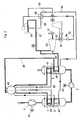
- Mehrere Ausführungsbeispiele der Erfindung sind in der Zeichnung dargestellt und werden im Folgenden näher erläutert. Es zeigen:
- Fig. 1
- das Schema einer Verdichteranlage, deren Verdichter durch eine Gasturbine angetrieben sind und
- Fig. 2
- das Schema einer elektromotorisch angetriebenen Verdichteranlage mit einer Ausnutzung der Verdichterabwärme gemäß der Erfindung.
- Die dargestellte Verdichterstation besteht aus zwei hintereinander geschalteten Verdichtern 1, 2 oder Verdichterstufengruppen. Die Verdichterstation dient zur Verdichtung von Gas in einer petrochemischen Anlage oder in einer Zwischenstation einer Pipeline zur Förderung von Gas oder ähnlichen Anwendungen. Zur Reduzierung der Antriebsleistung für die Verdichter 1, 2 ist in dem Gasstrom zwischen den Verdichtern 1, 2 ein Zwischenkühler 3 und zur Begrenzung der Gastemperatur ist hinter dem zweiten Verdichter 2 in der zu einem Endverbraucher führenden Leitung 4 ein Nachkühler 5 angeordnet. Der Zwischenkühler 3 und der Nachkühler 5 sind mit Wärmeaustauschflächen 6, 7 versehen. Es können auch mehr als zwei Verdichter oder Verdichterstufengruppen in der Verdichterstation vorgesehen werden, wobei jeweils zwischen zwei Verdichtern ein Zwischenkühler 3 und hinter dem letzten Verdichter der Nachkühler 5 angeordnet ist.
- Die in der
Fig. 1 dargestellte Verdichterstation, die nicht beansprucht wird, wird durch eine Gasturbinenanlage 8 angetrieben, der ein Abhitzekessel 9 in Verbindung mit einer Dampfturbine 10 nachgeschaltet ist. Die Gasturbinenanlage 8 besteht aus einem Brennluftverdichter 11, einer Brennkammer 12 und der eigentlichen Gasturbine 13. Die Ausgangswelle der Gasturbine 13 ist über ein Getriebe 14 mit den Verdichtern 1, 2 gekoppelt. Auf der Ausgangswelle der Gasturbine 13 ist ein Gasturbinengenerator 15 angeordnet, der elektrische Energie in das werkseigene oder in das öffentliche Stromnetz liefert. Bei dem Einsatz von Gasturbinen in der Leistungsklasse von 10 - 25 MW können die notwendigen Gesamt-Antriebsleistungen der Verdichter 1, 2 nur über höhere Leistungen der Dampfturbine 10 und damit durch erhöhte Feuerungstemperaturen im Abhitzekessel 9 erreicht werden. In diesem Fall sind die Gasturbine 13 und die Dampfturbine 10 als Einwellenstrang ausgebildet. Aus Gründen einer vereinfachten Darstellung ist ein solcher Einwellenstrang nicht gezeigt. - Im Abgasstrom kann hinter der Gasturbine 13 vorteilhafterweise eine mit Erdgas betriebene Zusatzfeuerung 17 mit einem Frischlüfter 16 vorgesehen werden. Die Regelung der Anlage erfolgt bei dem oben genannten Einwellenstrang ausschließlich über die Zusatzfeuerung, wodurch höchste Flexibilität bei der Teillastfahrweise und bei sich ändernden Ansaugbedingungen der Verdichter 1, 2 erreicht wird. Ist die Gasturbinen-Antriebsleistung für die Verdichter 1 und 2 ausreichend, so wird der Dampfturbinenkreislauf zur reinen Stromerzeugung oder als Kraft-Wärme-Kopplungs-Anlage genutzt. Über die installierte Zusatzfeuerung 17 und über den Frischlüfter 16 können bei entsprechender Gasturbinen-Teillast oder im Falle eines Schnellschlusses der Gasturbine 13 die Bedingungen des Dampfturbinen-Kreislaufes konstant gehalten werden. Bei einer Ausführung der Anlage als Einwellenstrang mit der oben genannten Aufgabenstellung kann der in
Fig. 1 gezeigte Gasturbinengenerator als Motor/Generator-System ausgebildet werden. Im Falle des Ausfalles der Dampfturbine 10 und der Gasturbine 13 kann die notwendige Antriebsleistung der Verdichter 1, 2 aus dem Netz bereitgestellt werden. Dann arbeitet das Motor/Generator-System im sogenannten Motorbetrieb. - Darüber hinaus steigt der elektrische Wirkungsgrad des Gesamtprozesses mit sinkender Last an, da der Gasturbinenanteil an der Gesamtleistung höher wird.
- Der Abhitzekessel 9 ist als Zweidruckkessel mit oder ohne Brennkammerberohrung konzipiert. Er enthält, wie in
Fig. 1 schematisch dargestellt, einen Hochdruckteil 18 und einen Niederdruckteil 19, die jeweils einen Speisewasservorwärmer 20, 21, einen Verdampfer 22, 23 und einen Überhitzer 24, 25 aufweisen. Der Speisewasservorwärmer 20 des Hochdruckteiles 18 setzt sich aus einem ersten Speisewasservorwärmer 20.1 und einem zweiten Speisewasservorwärmer 20.2 zusammen. Die jeweiligen Speisewasservorwärmer 20.2, 21, Verdampfer 22, 23 und Überhitzer 24, 25 stehen jeweils mit einer außen liegenden Dampftrommel 26, 27 in Verbindung, wenn diese Komponenten im Naturumlauf oder im Zwangumlauf betrieben werden. - Der Überhitzer 24 des Hochdruckteiles 18 ist über eine Hochdruckdampfleitung 28 mit dem Eingangs- oder Hochdruckteil der Dampfturbine 10 und der Überhitzer 25 des Niederdruckteiles 19 ist über eine Niederdruckdampfleitung 29 mit dem Niederdruckteil der Dampfturbine 10 verbunden. Die Dampfturbine 10 treibt in diesem Ausführungsbeispiel einen Generator 30 zur Energieerzeugung an.
- Der Austritt der Dampfturbine 10 ist mit einem Kondensator 31 verbunden. An den Kondensator 31 ist eine Kondensatleitung 32 angeschlossen, in der eine Kondensatpumpe 33 angeordnet ist, die über einen Wasser/Wasser/Wärmetauscher 34 zu einem Entgaser 35 geführt ist. Der Entgaser 35 ist über eine Niederdruckspeisewasserleitung 36, in der eine Niederdruckspeisewasserpumpe 37 angeordnet ist, mit dem Speisewasservorwärmer 21 des Niederdruckteiles 19 des Abhitzekessels 9 verbunden.
- Die Entgasung des Kondensats erfolgt durch Niederdruckdampf aus dem Niederdruckteil 19 des Abhitzekessels 9. Ein weiterer Teil des Niederdruckdampfes kann über eine von der Niederdruckdampfleitung 29 abzweigende Zweigleitung 38 einem externen Verbraucher vorteilhafterweise zur Fernwärmeversorgung, zur Brennstoffvorwärmung oder als Prozessdampf zugeführt werden.
- Um die in dem Zwischenkühler 3 und dem Nachkühler 5 anfallenden Abwärmepotentiale nutzbringend zu verwerten, sind die Wärmeaustauschflächen 6, 7 des Zwischenkühlers 3 und des Nachkühlers 5 in den Wasser-Dampf-Kreislauf des der Gasturbine 13 nachgeschalteten Abhitzekessels 9 eingebunden. Dazu ist an den Entgaser 35 eine Hochdruckspeisewasserleitung 39 angeschlossen, in der eine Hochdruckspeisewasserpumpe 40 angeordnet ist. Die Hochdruckspeisewasserleitung 39 ist durch den Wasser/Wasser/Wärmetauscher 34 hindurchgeführt und an den ersten Speisewasservorwärmer 20.1 des Hochdruckteiles 18 des Abhitzekessels 9 angeschlossen, der in dem Bereich des Austrittes des Abhitzekessels 9 angeordnet ist, an dem das Turbinenabgas seine niedrigste Temperatur erreicht hat. In dem außerhalb des Abhitzekessels 9 liegenden Wasser/Wasser-Wärmetauscher 34 wird die Temperatur des Speisewassers an dem Eintritt in den ersten Speisewasservorwärmer 20.1 durch das Kondensat so weit abgesenkt, dass die Abgastemperatur hinter dem Abhitzekessel 9 noch weiter reduziert werden kann. Der erste Speisewasservorwärmer 20.1 stellt in diesem Zusammenwirken eine zusätzliche Wärmesenke am kalten Ende des Abhitzekessels 9 dar. Eine solche Wärmesenke ist zur Erreichung einer wirtschaftlichen Gasaustrittstemperatur notwendig, weil anderenfalls die Nutzung der externen Abwärme der Verdichter 1, 2 zu einer verminderten Abwärmenutzung der Turbinenabgase bei Vermeidung einer Vorverdampfung in dem zweiten, im heißeren Teil des Abhitzekessels 9 liegenden Speisewasservorwärmer 20.2 des Hochdruckteiles 18 führen würde.
- Von dem am kalten Ende des Abhitzekessels 9 angeordneten ersten Speisewasservorwärmer 20.1 ist die Hochdruckspeisewasserleitung 39 zu der Wärmetauscherfläche 6 des Zwischenkühlers 3 und von dort zu der Wärmetauscherfläche 7 des Nachkühlers 5 weitergeführt. Im Anschluss an den Nachkühler 5 verbindet die Hochdruckspeisewasserleitung 39 die Wärmeaustauschfläche 7 des Nachkühlers 5 mit dem zweiten Speisewasservorwärmer 20.2 des Hochdruckteiles 18 des Abhitzekessels 9. Über eine durch ein Ventil absperrbare Bypassleitung 41 können vorteilhafterweise die Wärmetauscherflächen 6, 7 in dem Zwischenkühler 3 und in dem Nachkühler 5 im Bedarfsfalle umgangen werden, wodurch das Speisewasser direkt von dem ersten Speisewasservorwärmer 20.1 in den zweiten Speisewasservorwärmer 20.2 des Hochdruckteiles 18 gelangt.
- In der in
Fig. 1 dargestellten Anlage wird durch die beschriebene Schaltung der am Wärmetausch beteiligten Flächen die in dem Zwischenkühler 3 und in dem Nachkühler 5 anfallende Abwärme auf das Speisewasser übertragen, das mit Hilfe einer Hochdruckspeisewasserpumpe 40 über die Wärmetauscherflächen 6, 7 der Kühler 3, 5 in den Hochdruckteil des Abhitzekessels 9 und der Dampfturbine 10 einspeist wird. Durch die Nutzung der Abwärmen der Verdichter 1, 2 kann die elektrische Leistung der Dampfturbine bei gleichem Brennstoffeinsatz um etwa 25 % gesteigert werden. - Werden die Verdichter 1, 2 zur Verdichtung eines Gases elektromotorisch angetrieben, so lässt sich die über die Kühler 3, 5 abgeführte Abwärme der Verdichter 1, 2 mit Hilfe des in
Fig. 2 gezeigten Wasser-Dampf-Kreislaufes eines Niederdruckdampferzeugers gemäß der Erfindung nutzbringend verwerten. Die Verdichter 1, 2 sind jeweils mit einem Elektromotor 42, 43 oder hintereinander geschaltet mit einem einzigen Elektromotor als Antrieb verbunden. Im Gasstrom zwischen den beiden hintereinander geschalteten Verdichtern 1, 2 oder Verdichterstufengruppen liegt wiederum der Zwischenkühler 3 und in der zu einem Endverbraucher führenden Leitung 4 ist der Nachkühler 5 angeordnet. Die Wärmetauscherflächen 6, 7 der Kühler 3, 5 sind als Heizflächen eines druckaufgeladenen Niederdruckdampferzeugers geschaltet, wodurch wegen der hier vorliegenden hohen Wärmestromdichten bevorzugterweise Zwangumlaufverdampfer zur Anwendung kommen. - In dem Zwischenkühler 3 sind, in Strömungsrichtung des Gases gesehen, ein erster, als Zwangumlaufverdampfer ausgebildeter Verdampfer 44 und ein Speisewasservorwärmer 45 angeordnet. In dem Nachkühler 5 sind, in Strömungsrichtung des Gases gesehen, ein Überhitzer 46 und ein zweiter, als Zwangumlaufverdampfer ausgebildeter Verdampfer 47 angeordnet. Die beiden Verdampfer 44, 47 stehen mit einer Dampftrommel 48 in Verbindung. Der Dampferzeuger kann auch als Zwangdurchlaufdampferzeuger ausgebildet sein. Im Falle von Zwanglaufverdampfern kann die Dampftrommel 48 durch eine Abscheiderflasche ersetzt werden.
- Der Überhitzer 46 ist eingangsseitig mit dem Dampfraum der Dampftrommel 48 und ausgangsseitig über eine Dampfleitung 49 mit der Eintrittseite einer Dampfturbine 50 verbunden. Die Dampfturbine 50 treibt in diesem Beispiel einen Generator 51 zur Energieerzeugung an.
- An den Ausgang der Dampfturbine 50 ist über eine Kondensatleitung 52 ein Kondensator 53 angeschlossen. Die Kondensatleitung 52, in der eine Kondensatpumpe 54 angeordnet ist, ist über einen Wasser/Wasser-Wärmetauscher 55 zu einem Entgaser 56 geführt. Von der Dampfleitung 49 ist vor deren Eintritt in die Dampfturbine 50 eine Dampfzweigleitung 57 abgezweigt und zu dem Entgaser 56 geführt.
- An den Entgaser 56 ist eine Speisewasserleitung 58 mit einer Speisewasserpumpe 59 angeschlossen. Die Speisewasserleitung 58 ist durch den Wasser/Wasser-Wärmetauscher 55 hindurchgeführt und mit dem Eingang des Speisewasservorwärmers 45 verbunden.
- Während bei der in
Fig. 1 dargestellten Anlage durch die Verwendung des Hochdruckspeisewassers als Kühlmedium die Wärmeauskopplung auf der Hochdruckseite des Dampferzeugers erfolgt, geschieht dies bei der Anlage gemäßFig. 2 durch die Komponenten eines Niederdruckdampferzeugers, wie Überhitzer, Verdampfer und Speisewasservorwärmer. Bei motorisch angetriebenen Verdichtern erfolgt damit die Wärmeauskopplung auf Dampfbasis über Niederdrucksysteme. Der erzeugte Dampf wird dabei in einer eigens dafür konzipierten Niederdruckdampfturbine, wie inFig. 2 dargestellt, zur Stromerzeugung genutzt oder auf die Niederdruckseite einer vorhandenen Dampfturbine geführt. Daneben kann der erzeugte Dampf für die Bereitstellung von Fernwärme, Prozessdampf und Brennstoffvorwärmung genutzt werden.
Claims (1)
- Vorrichtung zur Ausnutzung der Abwärme von mehreren hintereinander geschalteten Verdichtern (1, 2) oder Verdichterstufengruppen zur Verdichtung eines Gases mit einem Zwischenkühler (3), der im Gasstrom jeweils zwischen zwei Verdichtern (1, 2) oder zwei Verdichterstufengruppen angeordnet und mit Wärmetauscherflächen (6) versehen ist, wobei die Wärmetauscherflächen (6) mit einem einen Speisewasservorwärmer (45), mehrere Verdampfer (44, 47), einen Überhitzer (46), einen Kondensator (53), einen Entgaser (56) und eine Speisewasserpumpe (59) aufweisenden Dampferzeuger für eine einen Generator (51) antreibende Dampfturbine (50) verbunden sind, wobei dem letzten Verdichter (2) ein Nachkühler (5) nachgeschaltet ist und wobei die Wärmetauscherflächen (6) des Zwischenkühlers (3) und Wärmetauscherflächen (7) des Nachkühlers (5) mit der Speisewasserpumpe (59) des Dampferzeugers in Verbindung stehen; und wobei
in dem Zwischenkühler (3) als wärmetauscherfläche (6) der Speisewasservorwärmer (45) und ein erster der Verdampfer (44) und in dem Nachkühler (5) als Wärmetauscherfläche (7) ein zweiter der Verdampfer (47), der mit dem ersten der Verdampfer (45) über eine Flasche oder eine Dampftrommel (48) parallel geschaltet ist, sowie der Überhitzer (46) eines druckaufgeladenen Niederdruck-Dampferzeugers angeordnet sind.
Applications Claiming Priority (2)
| Application Number | Priority Date | Filing Date | Title |
|---|---|---|---|
| DE102004020753 | 2004-04-27 | ||
| DE102004020753A DE102004020753A1 (de) | 2004-04-27 | 2004-04-27 | Vorrichtung zur Ausnutzung der Abwärme von Verdichtern |
Publications (2)
| Publication Number | Publication Date |
|---|---|
| EP1591644A1 EP1591644A1 (de) | 2005-11-02 |
| EP1591644B1 true EP1591644B1 (de) | 2011-02-09 |
Family
ID=34927013
Family Applications (1)
| Application Number | Title | Priority Date | Filing Date |
|---|---|---|---|
| EP04024724A Expired - Lifetime EP1591644B1 (de) | 2004-04-27 | 2004-10-16 | Vorrichtung zur Ausnutzung der Abwärme von Verdichtern |
Country Status (9)
| Country | Link |
|---|---|
| US (1) | US7269956B2 (de) |
| EP (1) | EP1591644B1 (de) |
| JP (1) | JP2005315244A (de) |
| AT (1) | ATE498062T1 (de) |
| CA (1) | CA2486013C (de) |
| DE (2) | DE102004020753A1 (de) |
| MX (1) | MXPA05002479A (de) |
| NO (1) | NO20045484L (de) |
| RU (1) | RU2416729C2 (de) |
Families Citing this family (71)
| Publication number | Priority date | Publication date | Assignee | Title |
|---|---|---|---|---|
| US8584464B2 (en) * | 2005-12-20 | 2013-11-19 | General Electric Company | Gas turbine engine assembly and method of assembling same |
| CA2645646C (en) * | 2006-03-14 | 2015-09-22 | John D. Pickard | Rotor assembly for a radial turbine |
| US7849692B2 (en) * | 2006-07-31 | 2010-12-14 | Caterpillar Inc | Segmented heat exchanger |
| US9003813B2 (en) * | 2006-12-14 | 2015-04-14 | University Of Massachusetts | Enhanced surface cooling of thermal discharges |
| JP4949977B2 (ja) * | 2007-09-04 | 2012-06-13 | 三菱重工業株式会社 | ガスタービンの吸気加熱制御装置 |
| RU2349764C1 (ru) * | 2007-11-20 | 2009-03-20 | Открытое акционерное общество "Инженерный Центр Энергетики Поволжья" | Теплоэлектроцентраль, надстроенная газотурбинной установкой |
| DE102008045450B4 (de) * | 2008-02-01 | 2010-08-26 | Siemens Aktiengesellschaft | Verfahren zum Betreiben eines thermodynamischen Kreislaufes sowie thermodynamischer Kreislauf |
| JP4196307B1 (ja) * | 2008-03-06 | 2008-12-17 | 三浦工業株式会社 | 蒸気システム |
| EP2199547A1 (de) * | 2008-12-19 | 2010-06-23 | Siemens Aktiengesellschaft | Abhitzedampferzeuger sowie ein Verfahren zum verbesserten Betrieb eines Abhitzedampferzeugers |
| IT1396001B1 (it) * | 2009-04-28 | 2012-11-09 | Nuovo Pignone Spa | Sistema di recupero dell'energia in un impianto per la compressione di gas |
| PL2438036T3 (pl) * | 2009-06-04 | 2017-09-29 | Genomatica, Inc. | Sposób oddzielania składników brzeczki fermentacyjnej |
| JP5495293B2 (ja) * | 2009-07-06 | 2014-05-21 | 株式会社日立産機システム | 圧縮機 |
| BE1018598A3 (nl) * | 2010-01-25 | 2011-04-05 | Atlas Copco Airpower Nv | Werkwijze voor het recupereren van enrgie. |
| US10094219B2 (en) | 2010-03-04 | 2018-10-09 | X Development Llc | Adiabatic salt energy storage |
| US8474277B2 (en) | 2010-07-13 | 2013-07-02 | General Electric Company | Compressor waste heat driven cooling system |
| DK2630342T3 (en) * | 2010-10-19 | 2014-12-15 | Alstom Technology Ltd | Method for operation of a gas / steam-combi power plant with cogeneration and a gas / steam-combi power plant for carrying out the process |
| JP5637808B2 (ja) * | 2010-10-21 | 2014-12-10 | 株式会社東芝 | 二酸化炭素回収方法及び二酸化炭素回収型汽力発電システム |
| US20120159923A1 (en) * | 2010-12-23 | 2012-06-28 | General Electric Company | System and method for using gas turbine intercooler heat in a bottoming steam cycle |
| JP2013057256A (ja) * | 2011-09-07 | 2013-03-28 | Ihi Corp | 圧縮機のエネルギー回収システム |
| DE102011122385A1 (de) * | 2011-12-24 | 2013-06-27 | Daimler Ag | Verfahren und Vorrichtung zur Entlüftung eines Abwärmenutzungskreislaufs in einem Fahrzeug |
| WO2013107557A2 (de) * | 2012-01-19 | 2013-07-25 | Siemens Aktiengesellschaft | Hilfsdampferzeugersystem für ein kraftwerk |
| FR2988166B1 (fr) * | 2012-03-13 | 2014-04-11 | Air Liquide | Procede et appareil de condensation d'un debit gazeux riche en dioxyde de carbone |
| FR2989454A1 (fr) * | 2012-04-16 | 2013-10-18 | Air Liquide | Installation de compression d'un flux gazeux humide |
| EP2669568A1 (de) * | 2012-05-31 | 2013-12-04 | Siemens Aktiengesellschaft | System und Verfahren zur Wiedergewinnung von Wärme aus einer Gasturbine |
| WO2014052927A1 (en) | 2012-09-27 | 2014-04-03 | Gigawatt Day Storage Systems, Inc. | Systems and methods for energy storage and retrieval |
| US8726629B2 (en) | 2012-10-04 | 2014-05-20 | Lightsail Energy, Inc. | Compressed air energy system integrated with gas turbine |
| US9388737B2 (en) * | 2012-10-04 | 2016-07-12 | Powerphase Llc | Aero boost—gas turbine energy supplementing systems and efficient inlet cooling and heating, and methods of making and using the same |
| WO2014055717A1 (en) | 2012-10-04 | 2014-04-10 | Kraft Robert J | Aero boost - gas turbine energy supplementing systems and efficient inlet cooling and heating, and methods of making and using the same |
| US9003763B2 (en) | 2012-10-04 | 2015-04-14 | Lightsail Energy, Inc. | Compressed air energy system integrated with gas turbine |
| DE102012218542B4 (de) * | 2012-10-11 | 2016-07-07 | Siemens Aktiengesellschaft | Verfahren zum flexiblen Betrieb einer Kraftwerksanlage |
| KR102009583B1 (ko) | 2012-10-26 | 2019-08-09 | 파워페이즈 엘엘씨 | 가스 터빈 에너지 보조 시스템 및 가열 시스템, 그리고 그 제작 및 이용 방법 |
| US9599070B2 (en) * | 2012-11-02 | 2017-03-21 | General Electric Company | System and method for oxidant compression in a stoichiometric exhaust gas recirculation gas turbine system |
| TWI654369B (zh) | 2012-11-02 | 2019-03-21 | 艾克頌美孚上游研究公司 | 在化學計量廢氣再循環氣渦輪系統中用於氧化劑壓縮之系統 |
| RU2553477C2 (ru) * | 2013-01-23 | 2015-06-20 | Аркадий Ефимович Зарянкин | Парогазовая установка |
| DE102013202111B4 (de) * | 2013-02-08 | 2015-06-03 | Siemens Aktiengesellschaft | Abwärmenutzung und Leistungserhöhung von Gasturbinenanlagen |
| WO2014158244A2 (en) * | 2013-03-14 | 2014-10-02 | Rolls-Royce North American Technologies, Inc. | Intercooled gas turbine with closed combined power cycle |
| US9557102B2 (en) * | 2013-06-19 | 2017-01-31 | Bechtel Hydrocarbon Technology Solutions, Inc. | Systems and methods for natural gas liquefaction capacity augmentation |
| MX369977B (es) * | 2013-09-26 | 2019-11-27 | Nooter/Eriksen Inc | Sistema y metodo de intercambio de calor para un generador de vapor de recuperacion de calor. |
| JP6267028B2 (ja) * | 2014-03-24 | 2018-01-24 | 三菱日立パワーシステムズ株式会社 | 排熱回収装置、これを備えているガスタービンプラント、及び排熱回収方法 |
| US10118108B2 (en) | 2014-04-22 | 2018-11-06 | General Electric Company | System and method of distillation process and turbine engine intercooler |
| BE1022138B1 (nl) * | 2014-05-16 | 2016-02-19 | Atlas Copco Airpower, Naamloze Vennootschap | Compressorinrichting en een daarbij toepasbare koeler |
| US10024195B2 (en) * | 2015-02-19 | 2018-07-17 | General Electric Company | System and method for heating make-up working fluid of a steam system with engine fluid waste heat |
| US10851677B2 (en) | 2015-08-28 | 2020-12-01 | Ingersoll-Rand Industrial U.S., Inc. | Boiler with integrated air compressor |
| US9490681B1 (en) | 2015-09-18 | 2016-11-08 | Ingersoll-Rand Company | Pulsed air to electric generator |
| US10487695B2 (en) | 2015-10-23 | 2019-11-26 | General Electric Company | System and method of interfacing intercooled gas turbine engine with distillation process |
| DE112015007098T5 (de) | 2015-12-21 | 2018-08-02 | Cummins Inc. | Integriertes steuersystem zur motorabwärmerückgewinnung mithilfe eines organic-rankine-cycle |
| JP6621348B2 (ja) * | 2016-03-10 | 2019-12-18 | 株式会社神戸製鋼所 | 圧縮空気貯蔵発電装置 |
| DE102016217886A1 (de) * | 2016-09-19 | 2018-03-22 | Siemens Aktiengesellschaft | Anlage und Verfahren mit einer Wärmekraftanlage und einem Prozessverdichter |
| US10233787B2 (en) | 2016-12-28 | 2019-03-19 | Malta Inc. | Storage of excess heat in cold side of heat engine |
| US10458284B2 (en) | 2016-12-28 | 2019-10-29 | Malta Inc. | Variable pressure inventory control of closed cycle system with a high pressure tank and an intermediate pressure tank |
| US20180179915A1 (en) * | 2016-12-28 | 2018-06-28 | General Electric Company | Steam turbine with steam storage system |
| US10233833B2 (en) | 2016-12-28 | 2019-03-19 | Malta Inc. | Pump control of closed cycle power generation system |
| US11053847B2 (en) | 2016-12-28 | 2021-07-06 | Malta Inc. | Baffled thermoclines in thermodynamic cycle systems |
| US10221775B2 (en) | 2016-12-29 | 2019-03-05 | Malta Inc. | Use of external air for closed cycle inventory control |
| US10801404B2 (en) | 2016-12-30 | 2020-10-13 | Malta Inc. | Variable pressure turbine |
| US10436109B2 (en) | 2016-12-31 | 2019-10-08 | Malta Inc. | Modular thermal storage |
| CZ307962B6 (cs) * | 2017-03-31 | 2019-09-18 | Vysoká Škola Báňská-Technická Univerzita Ostrava | Zařízení pro využití kompresního tepla |
| CZ307476B6 (cs) * | 2017-03-31 | 2018-10-03 | Vysoká Škola Báňská-Technická Univerzita Ostrava | Zařízení pro využití kompresního tepla |
| CN107288888B (zh) * | 2017-08-10 | 2019-04-05 | 上海赛捷能源科技有限公司 | 空气压缩机热回收系统 |
| CN109099405B (zh) * | 2018-09-05 | 2024-05-24 | 南京熵㶲新能源科技有限公司 | 一种蒸汽发生器系统及方法 |
| RU2738298C2 (ru) * | 2019-04-05 | 2020-12-11 | Федеральное государственное бюджетное образовательное учреждение высшего образования "Российский государственный университет туризма и сервиса" (ФГБОУ ВО "РГУТИС") | Привод компрессора теплонасосной установки |
| WO2021097413A1 (en) | 2019-11-16 | 2021-05-20 | Malta Inc. | Pumped heat electric storage system |
| US11286804B2 (en) | 2020-08-12 | 2022-03-29 | Malta Inc. | Pumped heat energy storage system with charge cycle thermal integration |
| US11454167B1 (en) | 2020-08-12 | 2022-09-27 | Malta Inc. | Pumped heat energy storage system with hot-side thermal integration |
| US11396826B2 (en) | 2020-08-12 | 2022-07-26 | Malta Inc. | Pumped heat energy storage system with electric heating integration |
| WO2022036098A1 (en) | 2020-08-12 | 2022-02-17 | Malta Inc. | Pumped heat energy storage system with steam cycle |
| US11486305B2 (en) | 2020-08-12 | 2022-11-01 | Malta Inc. | Pumped heat energy storage system with load following |
| US11480067B2 (en) * | 2020-08-12 | 2022-10-25 | Malta Inc. | Pumped heat energy storage system with generation cycle thermal integration |
| EP4296477A3 (de) | 2020-08-12 | 2024-02-28 | Malta Inc. | Gepumptes wärmeenergiespeichersystem mit modularer turbomaschine |
| EP4430285A4 (de) | 2021-12-14 | 2025-11-26 | Malta Inc | Mit kohlegefeuerter energieerzeugungseinheit integriertes pumpwärmespeichersystem |
| CN116291883B (zh) * | 2023-04-23 | 2025-05-23 | 西安热工研究院有限公司 | 一种燃气蒸汽联合循环机组冷端控温系统及方法 |
Family Cites Families (14)
| Publication number | Priority date | Publication date | Assignee | Title |
|---|---|---|---|---|
| JPS56115896A (en) * | 1980-02-19 | 1981-09-11 | Kawasaki Heavy Ind Ltd | Gas compressor plant equipped with power recovering means |
| DE3224577A1 (de) | 1982-07-01 | 1984-01-05 | Rudolf Dr. 6800 Mannheim Wieser | Kombinierte gasturbinen/dampfturbinenanlage |
| DE4237665A1 (de) * | 1992-11-07 | 1994-05-11 | Asea Brown Boveri | Verfahren zum Betrieb einer Kombianlage |
| US5375410A (en) * | 1993-01-25 | 1994-12-27 | Westinghouse Electric Corp. | Combined combustion and steam turbine power plant |
| RU2084644C1 (ru) * | 1994-05-31 | 1997-07-20 | Ивановский государственный энергетический университет | Способ повышения эффективности парогазовой установки с дожиганием и промежуточным воздухоохладителем газотурбинной установки |
| JPH08218894A (ja) * | 1995-02-15 | 1996-08-27 | Kawasaki Heavy Ind Ltd | 燃料ガス圧縮機の中間冷却装置 |
| DE19512466C1 (de) * | 1995-04-03 | 1996-08-22 | Siemens Ag | Verfahren zum Betreiben eines Abhitzedampferzeugers sowie danach arbeitender Abhitzedampferzeuger |
| DE19527537C1 (de) * | 1995-07-27 | 1996-09-26 | Siemens Ag | Verfahren zum Betreiben einer Gas- und Dampfturbinenanlage sowie danach arbeitende Anlage |
| GB2307277A (en) | 1995-11-17 | 1997-05-21 | Branko Stankovic | Combined cycle powerplant with gas turbine cooling |
| JPH09264158A (ja) * | 1996-03-29 | 1997-10-07 | Mitsubishi Gas Chem Co Inc | ガスタービンサイクル |
| JPH11343865A (ja) * | 1998-06-02 | 1999-12-14 | Mitsubishi Heavy Ind Ltd | 深冷タービン発電システム |
| JP4346213B2 (ja) * | 2000-06-06 | 2009-10-21 | 株式会社東芝 | コンバインドサイクル発電プラント |
| SE518504C2 (sv) * | 2000-07-10 | 2002-10-15 | Evol Ingenjoers Ab Fa | Förfarande och system för kraftproduktion, samt anordnigar för eftermontering i system för kraftproduktion |
| DE10155508C5 (de) | 2000-11-28 | 2008-10-30 | Man Turbo Ag | Verfahren und Vorrichtung zur Erzeugung von elektrischer Energie |
-
2004
- 2004-04-27 DE DE102004020753A patent/DE102004020753A1/de not_active Withdrawn
- 2004-10-07 US US10/960,375 patent/US7269956B2/en not_active Expired - Fee Related
- 2004-10-16 AT AT04024724T patent/ATE498062T1/de active
- 2004-10-16 DE DE502004012175T patent/DE502004012175D1/de not_active Expired - Lifetime
- 2004-10-16 EP EP04024724A patent/EP1591644B1/de not_active Expired - Lifetime
- 2004-10-28 CA CA002486013A patent/CA2486013C/en not_active Expired - Fee Related
- 2004-12-09 RU RU2004136074/06A patent/RU2416729C2/ru active
- 2004-12-16 NO NO20045484A patent/NO20045484L/no not_active Application Discontinuation
- 2004-12-17 JP JP2004366923A patent/JP2005315244A/ja not_active Ceased
-
2005
- 2005-03-04 MX MXPA05002479A patent/MXPA05002479A/es active IP Right Grant
Also Published As
| Publication number | Publication date |
|---|---|
| ATE498062T1 (de) | 2011-02-15 |
| RU2416729C2 (ru) | 2011-04-20 |
| US7269956B2 (en) | 2007-09-18 |
| DE502004012175D1 (de) | 2011-03-24 |
| JP2005315244A (ja) | 2005-11-10 |
| CA2486013C (en) | 2008-01-08 |
| DE102004020753A1 (de) | 2005-12-29 |
| US20050235625A1 (en) | 2005-10-27 |
| RU2004136074A (ru) | 2006-05-20 |
| NO20045484D0 (no) | 2004-12-16 |
| CA2486013A1 (en) | 2005-10-27 |
| EP1591644A1 (de) | 2005-11-02 |
| NO20045484L (no) | 2005-10-28 |
| MXPA05002479A (es) | 2005-10-31 |
Similar Documents
| Publication | Publication Date | Title |
|---|---|---|
| EP1591644A1 (de) | Vorrichtung zur Ausnutzung der Abwärme von Verdichtern | |
| DE69429769T2 (de) | Mehrwellen, zwischenheizungsgasturbine mit zwischenkühlung und wärmerückgewinnung | |
| EP0523467B1 (de) | Verfahren zum Betreiben einer Gas- und Dampfturbinenanlage und Anlage zur Durchführung des Verfahrens | |
| DE60315823T2 (de) | Verfahren und einrichtung zur stromerzeugung aus der im kern mindestens eines hochtemperatur-kernreaktors erzeugten wärme | |
| EP0720689B1 (de) | Vorrichtung zur kühlung des kühlmittels der gasturbine einer gas- und dampfturbinenanlage | |
| EP1893848A2 (de) | Dampferzeugungsanlage und verfahren zum betreiben und nachrüsten einer dampferzeuganlage | |
| EP2447506A2 (de) | System zur Erzeugung mechanischer und/oder elektrischer Energie | |
| EP2101051A1 (de) | Speicherung elektrischer Energie mit Wärmespeicher und Rückverstromung mittels eines thermodynamischen Kreisprozesses | |
| WO1999019608A1 (de) | Gas- und dampfturbinenanlage und verfahren zum betreiben einer derartigen anlage | |
| EP0778397A2 (de) | Verfahren zum Betrieb einer mit einem Abhitzedampferzeuger und einem Dampfverbraucher kombinierten Dampfturbogruppe | |
| EP3559564B1 (de) | Verfahren und vorrichtung zur erzeugung von prozesskälte und prozessdampf | |
| EP0515911A1 (de) | Verfahren zum Betreiben einer Gas- und Dampfturbinenanlage und entsprechende Anlage | |
| EP0592059B1 (de) | Verfahren und Vorrichtung zum Verdichten von Luft | |
| EP0220510B1 (de) | Druckaufgeladen betreibbare Feuerung für einen Dampferzeuger | |
| WO2005056994A1 (de) | Luftspeicherkraftanlage | |
| WO1999057421A1 (de) | Gas- und dampfturbinenanlage | |
| DE10155508C5 (de) | Verfahren und Vorrichtung zur Erzeugung von elektrischer Energie | |
| DE19720789B4 (de) | Verfahren und Vorrichtung zur Erzeugung von Dampf | |
| DE19627425A1 (de) | Verfahren zum Betrieb einer Hybrid-Solar-Kombianlage sowie eine Hybrid-Solar-Kombianlage | |
| EP1870646A2 (de) | Verfahren und Vorrichtung zur Rückgewinnung von Kondensationswärme aus einem thermodynamischen Kreisprozess | |
| DE4015104A1 (de) | Kombinierte waermekraftanlage | |
| EP2559867A1 (de) | Verfahren zum Erzeugen von elektrischer Energie mittels eines Kombikraftwerkes sowie Kombikraftwerk zur Durchführung des Verfahrens | |
| WO1995025880A1 (de) | Verfahren zum betreiben eines abhitzedampferzeugers sowie danach arbeitender abhitzedampferzeuger | |
| EP0349611A1 (de) | Kombinierte gas-dampfturbinenanlage | |
| DE102011114199B4 (de) | Verfahren zur thermischen und thermoelektrischen Abgas- oder Heissgaswärmenutzung mit Dampfkreislauf, sowie Einrichtung zur Abgas- oder Heissgaswärmenutzung |
Legal Events
| Date | Code | Title | Description |
|---|---|---|---|
| PUAI | Public reference made under article 153(3) epc to a published international application that has entered the european phase |
Free format text: ORIGINAL CODE: 0009012 |
|
| AK | Designated contracting states |
Kind code of ref document: A1 Designated state(s): AT BE BG CH CY CZ DE DK EE ES FI FR GB GR HU IE IT LI LU MC NL PL PT RO SE SI SK TR |
|
| AX | Request for extension of the european patent |
Extension state: AL HR LT LV MK |
|
| 17P | Request for examination filed |
Effective date: 20051006 |
|
| AKX | Designation fees paid |
Designated state(s): AT BE BG CH CY CZ DE DK EE ES FI FR GB GR HU IE IT LI LU MC NL PL PT RO SE SI SK TR |
|
| 17Q | First examination report despatched |
Effective date: 20061227 |
|
| RAP1 | Party data changed (applicant data changed or rights of an application transferred) |
Owner name: MAN DIESEL & TURBO SE |
|
| GRAP | Despatch of communication of intention to grant a patent |
Free format text: ORIGINAL CODE: EPIDOSNIGR1 |
|
| GRAS | Grant fee paid |
Free format text: ORIGINAL CODE: EPIDOSNIGR3 |
|
| GRAA | (expected) grant |
Free format text: ORIGINAL CODE: 0009210 |
|
| AK | Designated contracting states |
Kind code of ref document: B1 Designated state(s): AT BE BG CH CY CZ DE DK EE ES FI FR GB GR HU IE IT LI LU MC NL PL PT RO SE SI SK TR |
|
| REG | Reference to a national code |
Ref country code: GB Ref legal event code: FG4D Free format text: NOT ENGLISH |
|
| REG | Reference to a national code |
Ref country code: CH Ref legal event code: EP |
|
| REG | Reference to a national code |
Ref country code: IE Ref legal event code: FG4D Free format text: LANGUAGE OF EP DOCUMENT: GERMAN |
|
| REF | Corresponds to: |
Ref document number: 502004012175 Country of ref document: DE Date of ref document: 20110324 Kind code of ref document: P |
|
| REG | Reference to a national code |
Ref country code: DE Ref legal event code: R096 Ref document number: 502004012175 Country of ref document: DE Effective date: 20110324 |
|
| REG | Reference to a national code |
Ref country code: SE Ref legal event code: TRGR |
|
| REG | Reference to a national code |
Ref country code: NL Ref legal event code: VDEP Effective date: 20110209 |
|
| PG25 | Lapsed in a contracting state [announced via postgrant information from national office to epo] |
Ref country code: ES Free format text: LAPSE BECAUSE OF FAILURE TO SUBMIT A TRANSLATION OF THE DESCRIPTION OR TO PAY THE FEE WITHIN THE PRESCRIBED TIME-LIMIT Effective date: 20110520 Ref country code: GR Free format text: LAPSE BECAUSE OF FAILURE TO SUBMIT A TRANSLATION OF THE DESCRIPTION OR TO PAY THE FEE WITHIN THE PRESCRIBED TIME-LIMIT Effective date: 20110510 Ref country code: PT Free format text: LAPSE BECAUSE OF FAILURE TO SUBMIT A TRANSLATION OF THE DESCRIPTION OR TO PAY THE FEE WITHIN THE PRESCRIBED TIME-LIMIT Effective date: 20110609 |
|
| PG25 | Lapsed in a contracting state [announced via postgrant information from national office to epo] |
Ref country code: SI Free format text: LAPSE BECAUSE OF FAILURE TO SUBMIT A TRANSLATION OF THE DESCRIPTION OR TO PAY THE FEE WITHIN THE PRESCRIBED TIME-LIMIT Effective date: 20110209 Ref country code: BG Free format text: LAPSE BECAUSE OF FAILURE TO SUBMIT A TRANSLATION OF THE DESCRIPTION OR TO PAY THE FEE WITHIN THE PRESCRIBED TIME-LIMIT Effective date: 20110509 Ref country code: NL Free format text: LAPSE BECAUSE OF FAILURE TO SUBMIT A TRANSLATION OF THE DESCRIPTION OR TO PAY THE FEE WITHIN THE PRESCRIBED TIME-LIMIT Effective date: 20110209 Ref country code: FI Free format text: LAPSE BECAUSE OF FAILURE TO SUBMIT A TRANSLATION OF THE DESCRIPTION OR TO PAY THE FEE WITHIN THE PRESCRIBED TIME-LIMIT Effective date: 20110209 Ref country code: PL Free format text: LAPSE BECAUSE OF FAILURE TO SUBMIT A TRANSLATION OF THE DESCRIPTION OR TO PAY THE FEE WITHIN THE PRESCRIBED TIME-LIMIT Effective date: 20110209 Ref country code: CY Free format text: LAPSE BECAUSE OF FAILURE TO SUBMIT A TRANSLATION OF THE DESCRIPTION OR TO PAY THE FEE WITHIN THE PRESCRIBED TIME-LIMIT Effective date: 20110209 |
|
| REG | Reference to a national code |
Ref country code: IE Ref legal event code: FD4D |
|
| PG25 | Lapsed in a contracting state [announced via postgrant information from national office to epo] |
Ref country code: EE Free format text: LAPSE BECAUSE OF FAILURE TO SUBMIT A TRANSLATION OF THE DESCRIPTION OR TO PAY THE FEE WITHIN THE PRESCRIBED TIME-LIMIT Effective date: 20110209 Ref country code: DK Free format text: LAPSE BECAUSE OF FAILURE TO SUBMIT A TRANSLATION OF THE DESCRIPTION OR TO PAY THE FEE WITHIN THE PRESCRIBED TIME-LIMIT Effective date: 20110209 Ref country code: IE Free format text: LAPSE BECAUSE OF FAILURE TO SUBMIT A TRANSLATION OF THE DESCRIPTION OR TO PAY THE FEE WITHIN THE PRESCRIBED TIME-LIMIT Effective date: 20110209 |
|
| PG25 | Lapsed in a contracting state [announced via postgrant information from national office to epo] |
Ref country code: SK Free format text: LAPSE BECAUSE OF FAILURE TO SUBMIT A TRANSLATION OF THE DESCRIPTION OR TO PAY THE FEE WITHIN THE PRESCRIBED TIME-LIMIT Effective date: 20110209 Ref country code: CZ Free format text: LAPSE BECAUSE OF FAILURE TO SUBMIT A TRANSLATION OF THE DESCRIPTION OR TO PAY THE FEE WITHIN THE PRESCRIBED TIME-LIMIT Effective date: 20110209 Ref country code: RO Free format text: LAPSE BECAUSE OF FAILURE TO SUBMIT A TRANSLATION OF THE DESCRIPTION OR TO PAY THE FEE WITHIN THE PRESCRIBED TIME-LIMIT Effective date: 20110209 |
|
| PLBE | No opposition filed within time limit |
Free format text: ORIGINAL CODE: 0009261 |
|
| STAA | Information on the status of an ep patent application or granted ep patent |
Free format text: STATUS: NO OPPOSITION FILED WITHIN TIME LIMIT |
|
| 26N | No opposition filed |
Effective date: 20111110 |
|
| REG | Reference to a national code |
Ref country code: DE Ref legal event code: R097 Ref document number: 502004012175 Country of ref document: DE Effective date: 20111110 |
|
| PG25 | Lapsed in a contracting state [announced via postgrant information from national office to epo] |
Ref country code: MC Free format text: LAPSE BECAUSE OF NON-PAYMENT OF DUE FEES Effective date: 20111031 |
|
| REG | Reference to a national code |
Ref country code: CH Ref legal event code: PL |
|
| PG25 | Lapsed in a contracting state [announced via postgrant information from national office to epo] |
Ref country code: CH Free format text: LAPSE BECAUSE OF NON-PAYMENT OF DUE FEES Effective date: 20111031 Ref country code: LI Free format text: LAPSE BECAUSE OF NON-PAYMENT OF DUE FEES Effective date: 20111031 |
|
| PG25 | Lapsed in a contracting state [announced via postgrant information from national office to epo] |
Ref country code: LU Free format text: LAPSE BECAUSE OF NON-PAYMENT OF DUE FEES Effective date: 20111016 |
|
| PG25 | Lapsed in a contracting state [announced via postgrant information from national office to epo] |
Ref country code: TR Free format text: LAPSE BECAUSE OF FAILURE TO SUBMIT A TRANSLATION OF THE DESCRIPTION OR TO PAY THE FEE WITHIN THE PRESCRIBED TIME-LIMIT Effective date: 20110209 |
|
| PG25 | Lapsed in a contracting state [announced via postgrant information from national office to epo] |
Ref country code: HU Free format text: LAPSE BECAUSE OF FAILURE TO SUBMIT A TRANSLATION OF THE DESCRIPTION OR TO PAY THE FEE WITHIN THE PRESCRIBED TIME-LIMIT Effective date: 20110209 |
|
| REG | Reference to a national code |
Ref country code: FR Ref legal event code: PLFP Year of fee payment: 12 |
|
| REG | Reference to a national code |
Ref country code: FR Ref legal event code: PLFP Year of fee payment: 13 |
|
| REG | Reference to a national code |
Ref country code: FR Ref legal event code: PLFP Year of fee payment: 14 |
|
| REG | Reference to a national code |
Ref country code: FR Ref legal event code: PLFP Year of fee payment: 15 |
|
| REG | Reference to a national code |
Ref country code: AT Ref legal event code: HC Ref document number: 498062 Country of ref document: AT Kind code of ref document: T Owner name: MAN ENERGY SOLUTIONS SE, DE Effective date: 20181204 |
|
| REG | Reference to a national code |
Ref country code: BE Ref legal event code: HC Owner name: MAN ENERGY SOLUTIONS SE; DE Free format text: DETAILS ASSIGNMENT: CHANGE OF OWNER(S), CHANGEMENT DE NOM DU PROPRIETAIRE; FORMER OWNER NAME: MAN DIESEL & TURBO SE Effective date: 20181217 |
|
| REG | Reference to a national code |
Ref country code: DE Ref legal event code: R081 Ref document number: 502004012175 Country of ref document: DE Owner name: MAN ENERGY SOLUTIONS SE, DE Free format text: FORMER OWNER: MAN DIESEL & TURBO SE, 86153 AUGSBURG, DE |
|
| PGFP | Annual fee paid to national office [announced via postgrant information from national office to epo] |
Ref country code: GB Payment date: 20211022 Year of fee payment: 18 Ref country code: SE Payment date: 20211020 Year of fee payment: 18 Ref country code: AT Payment date: 20211021 Year of fee payment: 18 Ref country code: DE Payment date: 20211020 Year of fee payment: 18 |
|
| PGFP | Annual fee paid to national office [announced via postgrant information from national office to epo] |
Ref country code: IT Payment date: 20211028 Year of fee payment: 18 Ref country code: FR Payment date: 20211021 Year of fee payment: 18 Ref country code: BE Payment date: 20211020 Year of fee payment: 18 |
|
| REG | Reference to a national code |
Ref country code: DE Ref legal event code: R119 Ref document number: 502004012175 Country of ref document: DE |
|
| REG | Reference to a national code |
Ref country code: SE Ref legal event code: EUG |
|
| REG | Reference to a national code |
Ref country code: AT Ref legal event code: MM01 Ref document number: 498062 Country of ref document: AT Kind code of ref document: T Effective date: 20221016 |
|
| REG | Reference to a national code |
Ref country code: BE Ref legal event code: MM Effective date: 20221031 |
|
| GBPC | Gb: european patent ceased through non-payment of renewal fee |
Effective date: 20221016 |
|
| PG25 | Lapsed in a contracting state [announced via postgrant information from national office to epo] |
Ref country code: FR Free format text: LAPSE BECAUSE OF NON-PAYMENT OF DUE FEES Effective date: 20221031 Ref country code: DE Free format text: LAPSE BECAUSE OF NON-PAYMENT OF DUE FEES Effective date: 20230503 Ref country code: AT Free format text: LAPSE BECAUSE OF NON-PAYMENT OF DUE FEES Effective date: 20221016 |
|
| PG25 | Lapsed in a contracting state [announced via postgrant information from national office to epo] |
Ref country code: SE Free format text: LAPSE BECAUSE OF NON-PAYMENT OF DUE FEES Effective date: 20221017 |
|
| PG25 | Lapsed in a contracting state [announced via postgrant information from national office to epo] |
Ref country code: BE Free format text: LAPSE BECAUSE OF NON-PAYMENT OF DUE FEES Effective date: 20221031 |
|
| PG25 | Lapsed in a contracting state [announced via postgrant information from national office to epo] |
Ref country code: IT Free format text: LAPSE BECAUSE OF NON-PAYMENT OF DUE FEES Effective date: 20221016 Ref country code: GB Free format text: LAPSE BECAUSE OF NON-PAYMENT OF DUE FEES Effective date: 20221016 |