EP1591604A2 - Tür zum Schliessen eines Verteilerschrankes oder - kasten in Gebäuden oder auf Baustellen - Google Patents
Tür zum Schliessen eines Verteilerschrankes oder - kasten in Gebäuden oder auf Baustellen Download PDFInfo
- Publication number
- EP1591604A2 EP1591604A2 EP05102699A EP05102699A EP1591604A2 EP 1591604 A2 EP1591604 A2 EP 1591604A2 EP 05102699 A EP05102699 A EP 05102699A EP 05102699 A EP05102699 A EP 05102699A EP 1591604 A2 EP1591604 A2 EP 1591604A2
- Authority
- EP
- European Patent Office
- Prior art keywords
- door
- window
- inserts
- insert
- rim
- Prior art date
- Legal status (The legal status is an assumption and is not a legal conclusion. Google has not performed a legal analysis and makes no representation as to the accuracy of the status listed.)
- Withdrawn
Links
Images


Classifications
-
- E—FIXED CONSTRUCTIONS
- E06—DOORS, WINDOWS, SHUTTERS, OR ROLLER BLINDS IN GENERAL; LADDERS
- E06B—FIXED OR MOVABLE CLOSURES FOR OPENINGS IN BUILDINGS, VEHICLES, FENCES OR LIKE ENCLOSURES IN GENERAL, e.g. DOORS, WINDOWS, BLINDS, GATES
- E06B7/00—Special arrangements or measures in connection with doors or windows
- E06B7/28—Other arrangements on doors or windows, e.g. door-plates, windows adapted to carry plants, hooks for window cleaners
- E06B7/30—Peep-holes; Devices for speaking through; Doors having windows
-
- H—ELECTRICITY
- H02—GENERATION; CONVERSION OR DISTRIBUTION OF ELECTRIC POWER
- H02B—BOARDS, SUBSTATIONS OR SWITCHING ARRANGEMENTS FOR THE SUPPLY OR DISTRIBUTION OF ELECTRIC POWER
- H02B1/00—Frameworks, boards, panels, desks, casings; Details of substations or switching arrangements
- H02B1/26—Casings; Parts thereof or accessories therefor
- H02B1/30—Cabinet-type casings; Parts thereof or accessories therefor
- H02B1/38—Hinged covers or doors
-
- E—FIXED CONSTRUCTIONS
- E06—DOORS, WINDOWS, SHUTTERS, OR ROLLER BLINDS IN GENERAL; LADDERS
- E06B—FIXED OR MOVABLE CLOSURES FOR OPENINGS IN BUILDINGS, VEHICLES, FENCES OR LIKE ENCLOSURES IN GENERAL, e.g. DOORS, WINDOWS, BLINDS, GATES
- E06B3/00—Window sashes, door leaves, or like elements for closing wall or like openings; Layout of fixed or moving closures, e.g. windows in wall or like openings; Features of rigidly-mounted outer frames relating to the mounting of wing frames
- E06B3/54—Fixing of glass panes or like plates
- E06B3/58—Fixing of glass panes or like plates by means of borders, cleats, or the like
- E06B3/5892—Fixing of window panes in openings in door leaves
Definitions
- the invention relates to doors made of plastic for closing inspection cabinets or wall boxes intended, for example, to contain the junctions of electricity, telephone, water or gas mains used in buildings or on building sites, which doors are of the so-called "ambidextrous" type in that, depending on the requirements, they must be able to be positioned equally well with the opening hinges on the right or on the left, for example as described in documents EP 1 398 439 A2 and EP 1 505 704 A2 to which extensive reference will be made.
- the doors are provided, integrally and at a short distance from the horizontal sides, with ventilation grilles having the slats inclined transversely and mutually converging outwards so that, however the door is arranged, with the hinges on the right or on the left, the upper grille always has the slats inclined, from the top downwards, towards the outside and therefore in the best condition for preventing entry of rain water into the box.
- the bottom grille has the slats always inclined, from the top downwards, towards the inside of the box and therefore in a condition not suitable for preventing entry of the rain water.
- the invention envisages forming on the door, at the time of moulding, one or more windows which have any suitable shape, for example a rectangular shape, and are designed such that they may be closed, directly by the user at the time of mounting, by snap-engaging inserts which, depending on the requirements, may consist for example of grilles which can be directed so that the slats are always able to prevent the entry of water through them or closed inserts made for example of transparent material, for viewing for example counters, remote control switches, relays or other devices which are situated inside the box and are thus visible from the outside without having to open the door.
- each insert could be mounted inside its own window with ease, in a very secure and vandal-proof manner, so that it cannot be removed from the outside but may instead be easily removed from the inside of the door.
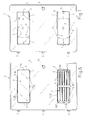
- S denotes the door made by means of plastic injection moulding, for example having a rectangular shape, with rounded corners, provided at the front and at the rear with a small raised perimetral rim A reinforced at the rear by horizontal and vertical raised ribs B coplanar with the rear perimetral rim, and provided on one vertical side with the hinging lugs C symmetrically spaced and on the other side, in a middle position, with the seat D for receiving the closing means which, like the hinges C, are not considered here in detail since they are outside the scope necessary for understanding the invention.
- the door S has been provided with a pair of windows 1 having the same shape, the same dimensions and the same functional characteristics, for example a rectangular shape, with the corners suitably rounded, and positioned centred, at a short distance from the horizontal sides of the door and parallel to them.
- each window 1 is circumscribed on the front side of the door by a small and continuous raised rim 2 and on the rear side the same window is circumscribed by a wider rim 3 which partly projects inside the said window 1 so as to act as a support for the insert later inserted in the said window and which, as can be seen in the detail according to Figures 3 and 8, is coplanar with and joined to the rear ribs B of the door.
- the rib 3 is not continuous and has small gaps 4 of the same length in the centre of the short sides and the long sides which also have similar gaps in zones symmetrically spaced from the central gap.
- the gaps 4 have, for example, a length of about 10-15 mm, for example about 12 mm.
- the long sides of the rim 3 are provided with three gaps 4 spaced for example from each other at an interval of about 50-52 mm.
- the gaps 4 are provided in order to allow through the parts of the mould which form on the internal perimeter of each window 1, small parallelepiped-shaped reliefs 5 which are parallel to the rims 2 and 3 and have the same length as the said gaps 4 and the outer side of which is substantially coplanar with the outer side of the door S, while their side directed towards the rear rim 3 is suitably spaced from this rim, as indicated by E in Figure 8, substantially at a distance slightly different from or about equal to the thickness of the said reliefs 5.
- the small semicircular recesses indicated by 6 in Figures 1, 2 and 3 are due to mould insert extractors which form the windows 1 in question and do not have a functional purpose.
- the perimetral edge of the inserts 7 and 8 is characterized by having a continuous part 9 with the same height E indicated in Figure 8, which is suitably tapered or inclined, such that one side G of the said inserts 7 and 8 has a surface smaller than that of the opposite side.
- the perimetral edge of the rim of the inserts 7 and 8, and more precisely that part of the perimetral edge which is not affected by the tapered part 9 (Fig. 10) is provided with recesses 10 having the same length as the said reliefs 5, all of which so that, as shown in the sequence of Figures 11 and 12, when positioning the insert 7 or 8 inside the window 1, so that it rests with its tapered perimetral part 9 against the reliefs 5, and pushing the said insert inside the window, as indicated by the arrow 11, the insert fits precisely into the said window and is retained inside it by snap-engagement of the reliefs 5 inside the recesses 10.
- the insert 7 or 8 rests with a large part of its perimeter on the bottom rim 3 and cannot be pushed beyond the latter, so as to thwart any attempt at breaking in.
- the insert 7 and 8 also engages fully and snugly with the window 1 and along its perimeter there is no play allowing the insertion of any break-in tools and, for this purpose, the outer edge 110 of the recesses 10 is suitably rounded.
- the door S is open, it is easy to remove the insert 7 or 8 from the window 1 by exerting on the insert a minimum thrust outwards, opposite to that indicated by 11, such that it is possible at any time to fit the window with any one of these inserts 7 or 8 and arrange them correctly.
- the door is supplied with a package containing a transparent closing piece 8 and a ventilation grille 7, so that, depending on whether the door is to be arranged with the hinges on the left or on the right, the closing piece 8 may for example be arranged in that window 1 which is closest to the instrument which must be visible, for example in the upper window, while in the other window it possible to arrange the grille 7 inclined with its slats, from the top downwards, towards the outside, so as to prevent the entry of rain water. If the user has special requirements, it is possible to buy an additional package containing closing piece and grille, in order to arrange, in both the windows 1 of the door, two transparent closing pieces or two ventilation grilles.
Landscapes
- Engineering & Computer Science (AREA)
- Civil Engineering (AREA)
- Structural Engineering (AREA)
- Power Engineering (AREA)
- Casings For Electric Apparatus (AREA)
- Switch Cases, Indication, And Locking (AREA)
- Investigating Or Analysing Materials By Optical Means (AREA)
- Operating, Guiding And Securing Of Roll- Type Closing Members (AREA)
- Testing Of Devices, Machine Parts, Or Other Structures Thereof (AREA)
Applications Claiming Priority (2)
| Application Number | Priority Date | Filing Date | Title |
|---|---|---|---|
| ITBO20040039 ITBO20040039U1 (it) | 2004-04-20 | 2004-04-20 | Sportello ambidestro per la chiusura di vani o di cassette ispezionabili per i servizi degli edifici o dei cantieri, dotato di una o piu |
| ITBO20040039U | 2004-04-20 |
Publications (2)
| Publication Number | Publication Date |
|---|---|
| EP1591604A2 true EP1591604A2 (de) | 2005-11-02 |
| EP1591604A3 EP1591604A3 (de) | 2011-01-19 |
Family
ID=34939159
Family Applications (1)
| Application Number | Title | Priority Date | Filing Date |
|---|---|---|---|
| EP05102699A Withdrawn EP1591604A3 (de) | 2004-04-20 | 2005-04-06 | Tür zum Schliessen eines Verteilerschrankes oder -Kasten in Gebäuden oder auf Baustellen |
Country Status (2)
| Country | Link |
|---|---|
| EP (1) | EP1591604A3 (de) |
| IT (1) | ITBO20040039U1 (de) |
Cited By (1)
| Publication number | Priority date | Publication date | Assignee | Title |
|---|---|---|---|---|
| CN103730851A (zh) * | 2013-12-31 | 2014-04-16 | 宁海县雁苍山电力设备厂 | 配电箱门板 |
Family Cites Families (4)
| Publication number | Priority date | Publication date | Assignee | Title |
|---|---|---|---|---|
| US3202881A (en) * | 1961-08-02 | 1965-08-24 | Square D Co | Electrical panelboard enclosure |
| FR2719441B1 (fr) * | 1994-04-27 | 1996-06-14 | Bcg | Coffret industriel à porte escamotable. |
| US5886868A (en) * | 1996-10-10 | 1999-03-23 | Eaton Corporation | Electrical distribution panel enclosure |
| IT256144Y1 (it) * | 2002-09-12 | 2004-04-13 | Eur Ex S R L | Sportello con telaio, in materia plastica, di uso facile e versatile,particolarmente per la chiusura dei vani a muro ispezionabili, contenenti le derivazioni delle reti elettriche, del telefono, dell'acqua o del gas poste a servizio degli edifici |
-
2004
- 2004-04-20 IT ITBO20040039 patent/ITBO20040039U1/it unknown
-
2005
- 2005-04-06 EP EP05102699A patent/EP1591604A3/de not_active Withdrawn
Cited By (1)
| Publication number | Priority date | Publication date | Assignee | Title |
|---|---|---|---|---|
| CN103730851A (zh) * | 2013-12-31 | 2014-04-16 | 宁海县雁苍山电力设备厂 | 配电箱门板 |
Also Published As
| Publication number | Publication date |
|---|---|
| EP1591604A3 (de) | 2011-01-19 |
| ITBO20040039U1 (it) | 2004-07-20 |
Similar Documents
| Publication | Publication Date | Title |
|---|---|---|
| US8258401B1 (en) | Zero profile while in-use electrical outlet cover | |
| US7598452B1 (en) | In-use outlet cover | |
| US9444179B1 (en) | Secure dual mount cover for outdoor electrical devices | |
| US7820911B1 (en) | Reversible protective cable chute assembly for routing low voltage cables through walls | |
| US6931893B2 (en) | Locking device for a meter socket | |
| US4572593A (en) | Display case | |
| US20090303666A1 (en) | Thermoplastic electrical enclosure | |
| US9478956B1 (en) | In use cover for outdoor electrical devices | |
| US6988341B2 (en) | Ventilated interlocking translucent blocks | |
| US4244483A (en) | Electrical wiring box | |
| KR100847095B1 (ko) | 납골함안치단의 납골함수납함 | |
| JP6943755B2 (ja) | 宅配ボックスのベース | |
| US4595115A (en) | Hidden panel connector | |
| JP3160499B2 (ja) | 分電盤 | |
| JP3031315U (ja) | 消火器格納箱 | |
| JP2020028327A (ja) | 宅配ボックス | |
| JP2019111247A (ja) | 宅配ボックス | |
| RU2353864C2 (ru) | Резервуар для горячей воды | |
| JPH0522099Y2 (de) | ||
| KR101667928B1 (ko) | 봉안단의 라이너함 | |
| US7044360B2 (en) | UPBOX / rc | |
| JPS6016674Y2 (ja) | 量水器筐用調節体 | |
| JPS6212785Y2 (de) | ||
| CN210158175U (zh) | 一种组装生产快速的化妆收纳盒 | |
| JP2003191952A (ja) | プラスチック製ロッカー |
Legal Events
| Date | Code | Title | Description |
|---|---|---|---|
| PUAI | Public reference made under article 153(3) epc to a published international application that has entered the european phase |
Free format text: ORIGINAL CODE: 0009012 |
|
| AK | Designated contracting states |
Kind code of ref document: A2 Designated state(s): AT BE BG CH CY CZ DE DK EE ES FI FR GB GR HU IE IS IT LI LT LU MC NL PL PT RO SE SI SK TR |
|
| AX | Request for extension of the european patent |
Extension state: AL BA HR LV MK YU |
|
| PUAL | Search report despatched |
Free format text: ORIGINAL CODE: 0009013 |
|
| AK | Designated contracting states |
Kind code of ref document: A3 Designated state(s): AT BE BG CH CY CZ DE DK EE ES FI FR GB GR HU IE IS IT LI LT LU MC NL PL PT RO SE SI SK TR |
|
| AX | Request for extension of the european patent |
Extension state: AL BA HR LV MK YU |
|
| RIC1 | Information provided on ipc code assigned before grant |
Ipc: E06B 3/58 20060101ALN20101210BHEP Ipc: H02B 1/44 20060101ALI20101210BHEP Ipc: E06B 7/30 20060101ALI20101210BHEP Ipc: E04F 19/08 20060101AFI20050708BHEP |
|
| AKY | No designation fees paid | ||
| REG | Reference to a national code |
Ref country code: DE Ref legal event code: R108 |
|
| REG | Reference to a national code |
Ref country code: DE Ref legal event code: R108 Effective date: 20110921 |
|
| STAA | Information on the status of an ep patent application or granted ep patent |
Free format text: STATUS: THE APPLICATION IS DEEMED TO BE WITHDRAWN |
|
| 18D | Application deemed to be withdrawn |
Effective date: 20110720 |