EP1591358B1 - Air chiller unit - Google Patents
Air chiller unit Download PDFInfo
- Publication number
- EP1591358B1 EP1591358B1 EP05004259A EP05004259A EP1591358B1 EP 1591358 B1 EP1591358 B1 EP 1591358B1 EP 05004259 A EP05004259 A EP 05004259A EP 05004259 A EP05004259 A EP 05004259A EP 1591358 B1 EP1591358 B1 EP 1591358B1
- Authority
- EP
- European Patent Office
- Prior art keywords
- vibration isolation
- air
- chiller unit
- bracket
- air chiller
- Prior art date
- Legal status (The legal status is an assumption and is not a legal conclusion. Google has not performed a legal analysis and makes no representation as to the accuracy of the status listed.)
- Expired - Lifetime
Links
Images


Classifications
-
- F—MECHANICAL ENGINEERING; LIGHTING; HEATING; WEAPONS; BLASTING
- F04—POSITIVE - DISPLACEMENT MACHINES FOR LIQUIDS; PUMPS FOR LIQUIDS OR ELASTIC FLUIDS
- F04B—POSITIVE-DISPLACEMENT MACHINES FOR LIQUIDS; PUMPS
- F04B39/00—Component parts, details, or accessories, of pumps or pumping systems specially adapted for elastic fluids, not otherwise provided for in, or of interest apart from, groups F04B25/00 - F04B37/00
- F04B39/0027—Pulsation and noise damping means
- F04B39/0044—Pulsation and noise damping means with vibration damping supports
-
- B—PERFORMING OPERATIONS; TRANSPORTING
- B64—AIRCRAFT; AVIATION; COSMONAUTICS
- B64D—EQUIPMENT FOR FITTING IN OR TO AIRCRAFT; FLIGHT SUITS; PARACHUTES; ARRANGEMENT OR MOUNTING OF POWER PLANTS OR PROPULSION TRANSMISSIONS IN AIRCRAFT
- B64D11/00—Passenger or crew accommodation; Flight-deck installations not otherwise provided for
-
- B—PERFORMING OPERATIONS; TRANSPORTING
- B64—AIRCRAFT; AVIATION; COSMONAUTICS
- B64D—EQUIPMENT FOR FITTING IN OR TO AIRCRAFT; FLIGHT SUITS; PARACHUTES; ARRANGEMENT OR MOUNTING OF POWER PLANTS OR PROPULSION TRANSMISSIONS IN AIRCRAFT
- B64D13/00—Arrangements or adaptations of air-treatment apparatus for aircraft crew or passengers, or freight space
- B64D13/06—Arrangements or adaptations of air-treatment apparatus for aircraft crew or passengers, or freight space the air being conditioned
- B64D2013/0603—Environmental Control Systems
- B64D2013/0629—Environmental Control Systems with subsystems for cooling food, catering or special loads
-
- Y—GENERAL TAGGING OF NEW TECHNOLOGICAL DEVELOPMENTS; GENERAL TAGGING OF CROSS-SECTIONAL TECHNOLOGIES SPANNING OVER SEVERAL SECTIONS OF THE IPC; TECHNICAL SUBJECTS COVERED BY FORMER USPC CROSS-REFERENCE ART COLLECTIONS [XRACs] AND DIGESTS
- Y02—TECHNOLOGIES OR APPLICATIONS FOR MITIGATION OR ADAPTATION AGAINST CLIMATE CHANGE
- Y02T—CLIMATE CHANGE MITIGATION TECHNOLOGIES RELATED TO TRANSPORTATION
- Y02T50/00—Aeronautics or air transport
- Y02T50/40—Weight reduction
Definitions
- the present invention relates to an air chiller unit (air cooling device) equipped in a body of an aircraft for supplying cooled air to foods or the like.
- Passenger aircrafts that travel long distances, such as international flights, are equipped with service carts storing meals and the like to be served to passengers, and galleys (kitchen areas) housing the service carts for preparing beverages and carrying out easy food preparation.
- the meals are cooked in advance in service facilities on the ground, placed on trays to be stored in service carts, and brought on board.
- the air chiller unit is disposed in a space provided on the ceiling or under the floor of the galley in the aircraft.
- the air chiller unit is equipped with a refrigeration cycle unit, which cools air by an evaporator disposed within a cooling air chamber and supplies the cooled air via a duct to the galley or the like.
- the air chiller unit Since the air chiller unit is mounted on an aircraft, the unit is required to be light weight and small, and since it is located near the passenger seats, the noise generated by the unit must be reduced.
- the refrigeration cycle unit incorporated in the air chiller unit has a compressor for a refrigerant, which is a rotary machine, and it is necessary that the compressor is provided with a vibration-isolation supporting mechanism.
- the support arrangement sacrificed the vibration isolation performance so as to provide sufficient durability to the 9-G load.
- An air chiller unit with the features of the preamble of claim 1 is known from JP-A-04184025 .
- the present invention provides an air chiller unit having a vibration isolation mounting mechanism for the compressor that has both load endurance property and vibration isolation property.
- the air chiller unit comprises a refrigeration cycle unit, a casing for housing the refrigeration cycle unit, and a pair of vibration isolation mounting devices for mounting a refrigerant compressor of the refrigeration cycle unit on the casing, the pair of vibration isolation mounting devices equipped with A-shaped vibration isolation members arranged so that peak portions thereof oppose one another.
- the vibration isolation mounting device comprises a triangular prism-shaped bracket, a vibration isolation member having an A-shaped cross-section disposed within the bracket, a cylindrical vibration isolation member disposed on an upper surface of the bracket, and a mounting bolt passing through said vibration isolation members.
- the present air chiller unit utilizes a pair of vibration isolation mounting devices as devices for mounting the compressor constituting the refrigeration cycle unit on a base plate of the casing, in which each vibration isolation mounting member is equipped with an A-shaped rubber vibration isolator.
- the A-shaped rubber vibration isolator is disposed within a triangular prism-shaped bracket and supports the compressor.
- the rubber vibration isolator with an A-shaped cross-section is basically soft, exhibiting advantageous absorption property to fine vibrations, but it cannot endure the application of large loads.
- the present invention adopts a structure in which two rubber vibration isolators with the A-shaped cross-section are arranged so that their peak portions (upper ends) face each other, with the periphery of the rubber vibration isolators surrounded with triangular prism-shaped brackets.
- the rubber vibration isolator that is disposed on the side not being compressed maintains its vibration absorption property, with the leg portions of the A-shaped rubber capable of deforming easily.
- the vibration isolator can exhibit a good vibration isolation property for even a large rotational torque applied when the compressor is started or stopped.
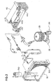
- FIGS. 1 and 2 are explanatory views showing the appearance of the air chiller unit according to the present invention, and the general structure of the refrigeration cycle unit thereof.
- An air chiller unit referred to as a whole by reference number 1 is equipped with a casing 10, a compressor 20 for a refrigerant disposed within the casing 10, a condenser 30, an evaporator 40 and a blower device 60 for blowing air.
- the compressor 20, which is a rotary machine, is mounted on a base plate of the casing 10 via a vibration isolation mounting device 26 according to the present invention.
- the refrigeration cycle unit of the air chiller unit is equipped with a compressor 20 driven by a motor, for compressing the refrigerant and sending out the same toward the condenser 30.
- the condenser 30 is equipped with a heat exchanger 300 for exchanging the gaseous refrigerant to a liquid-phase refrigerant.
- the liquid-phase refrigerant is stored in a receiver drier 310 disposed adjacent to the heat exchanger.
- the liquid-phase refrigerant in the receiver drier 310 is sent via a piping to an evaporator 40 disposed within the air cooling chamber defined by the wall of the casing 10.
- the liquid-phase refrigerant travels through an expansion valve 410 equipped to the evaporator 40 and sent to a heat exchanger 400 of the evaporator.
- the refrigerant is evaporated in the heat exchanger 400 and cools the air passing the heat exchanger 400.
- the expansion valve 410 changes the opening of the valve according to the pressure and temperature of the refrigerant returning toward the compressor 20 from the evaporator 40, to thereby control the flow rate of the refrigerant being sent to the evaporator.
- the blower device 60 has two fans mounted on both ends of a shaft of a motor, and blows air toward the condenser 30 and also blows the cooled air generated in the air cooling chamber toward the service carts placed in the galley of the passenger cabin.
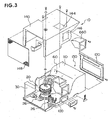
- FIGS. 3 and 4 are explanatory views showing the structure of a casing of the air chiller unit according to the present invention.
- the casing 10 comprises a base plate 100, and on the base plate 100 are mounted devices such as the compressor 20.
- the base plate 100 is formed of a honeycomb panel manufactured by sandwiching a core member having a honeycomb structure between two parallel plate members.
- the honeycomb panel is light weight and has superior flexural rigidity, so the base plate 100 is capable of supporting devices such as the compressor 20 by itself.
- the honeycomb panel Since the honeycomb panel is formed to have air sealed in the honeycomb core, it has high heat insulating property. Therefore, it is suitable for forming the air cooling chamber or the like.
- the partition member 110 formed of a honeycomb panel is disposed on the base plate 100.
- This partition member 110 is for dividing the air chiller unit into a side having the condenser and a side having the evaporator, and on this partition member 110 is mounted the blower device 60.
- the partition member constitutes a portion of the air cooling chamber 130.
- a lid member 120 is mounted on the opening of the partition member 110.
- a cover member 140 is mounted above the base plate 100, by which the compressor 20 and the blower device 60 are covered.
- the cover member 140 has rectangular openings 144 and 146 on the upper surface and side surface thereof.
- the openings 144 and 146 are for attaching a duct for sending cooled air to the galley, wherein only one of the two openings will be used.
- Amesh member 148 is attached to the end of the cover member 140, by which the front face of the condenser 30 is covered.
- a round hole 142 for the blower device is formed to the partition member 110.
- a drain pan 150 for receiving water drops condensed on the evaporator is attached to the bottom of the air cooling chamber.
- the drain pan 150 is equipped with a drain valve 160.
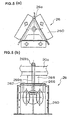
- FIG. 5 shows the vibration isolation mounting device 26 of the present invention, wherein FIG. 5 (a) is a plan view and FIG. 5(b) is a front view thereof.
- the vibration isolation mounting device 26 has a triangular prism-shaped bracket 260, and the bracket 260 is equipped with a ceiling plate 262.
- a cylindrical second vibration isolation member 268 is disposed above the triangular prism-shaped first vibration isolation member 266 with the ceiling plate 262 interposed therebetween, and a mounting bracket 20a of the compressor is attached to the base plate of the casing via a bolt 269a and a nut 269b passing therethrough.
- FIG. 6 shows the overall structure of the bracket 260, wherein FIG. 6 (a) is a plan view and FIG. 6(b) is a front view thereof.
- the triangular prism-shaped bracket 260 is composed of a first bracket member 261 defining two surfaces of the triangular prism and a second bracket member 263 defining the remaining one surface thereof.
- the members are formed by bending a metal plate and joined by spot welding W 1 at the joint portion.
- the members 261 and 263 are provided with screw holes 261b and 263b used for attaching the same to the base plate of the casing, and the ceiling plate is provided with a bolt hole 262a for the bolt to pass through.
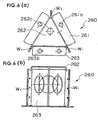
- FIG. 7 shows the structure of the first bracket member 261, wherein FIG. 7 (a) is a plan view and FIG. 7 (b) is a front view thereof.
- the first bracket member 261 is formed by bending a metal plate, and has a ceiling plate 262.
- the two wall faces of the triangular prism are provided with openings 261a for reducing the weight thereof.
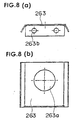
- FIG. 8 shows the structure of the second bracket member 263, wherein FIG. 8 (a) is a plan view and FIG. 8 (b) is a front view thereof.
- the second bracket member 263 is formed by bending a metal plate, provided with screw holes 263b and an opening 263a for reducing the weight thereof.
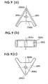
- FIG. 9 shows the first vibration isolation member 266, wherein FIG. 9(a) is an upper view, FIG. 9(b) is a front view and FIG. 9(c) is a bottom view thereof.
- the first vibration isolation member 266 is formed of an elastic member such as rubber, and shaped so that a recessed portion 266b is formed on one wall of a triangular prism.
- the first vibration isolation member has a cross-sectional shape that looks like the letter A of the alphabet.
- the surface coming into contact with the ceiling plate of the bracket is formed to have a chamfered portion 266c.
- a bolt hole 266a for allowing a mounting bolt to be passed through is formed at a position close to a peak portion 266d of the fist vibration isolation member having the substantially A-shaped planar shape.
- the peak portion 266d is formed as a flat surface.
- Two vibration isolation mounting devices 26 are used as a pair to support the compressor, and the peak portions 266d of the devices are arranged to oppose one another.
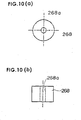
- FIG. 10 shows the second vibration isolationmember, wherein FIG. 10 (a) is a plan view and FIG. 10 (b) is a front view thereof.
- the second vibration isolation member 268 is formed of an elastic member such as rubber, designed to have a bolt hole 268a formed at a center of a cylindrical member.
- the present invention enables to provide an air chiller unit equipped with a compressor mounting device capable of enduring a large load while exhibiting a sufficient vibration isolation performance.
Landscapes
- Engineering & Computer Science (AREA)
- Aviation & Aerospace Engineering (AREA)
- Health & Medical Sciences (AREA)
- General Health & Medical Sciences (AREA)
- Pulmonology (AREA)
- Mechanical Engineering (AREA)
- General Engineering & Computer Science (AREA)
- Vibration Prevention Devices (AREA)
- Compressor (AREA)
Applications Claiming Priority (2)
| Application Number | Priority Date | Filing Date | Title |
|---|---|---|---|
| JP2004129760 | 2004-04-26 | ||
| JP2004129760A JP4291730B2 (ja) | 2004-04-26 | 2004-04-26 | エアチラー装置 |
Publications (3)
| Publication Number | Publication Date |
|---|---|
| EP1591358A2 EP1591358A2 (en) | 2005-11-02 |
| EP1591358A3 EP1591358A3 (en) | 2006-11-08 |
| EP1591358B1 true EP1591358B1 (en) | 2008-04-09 |
Family
ID=34933964
Family Applications (1)
| Application Number | Title | Priority Date | Filing Date |
|---|---|---|---|
| EP05004259A Expired - Lifetime EP1591358B1 (en) | 2004-04-26 | 2005-02-26 | Air chiller unit |
Country Status (4)
| Country | Link |
|---|---|
| US (1) | US7225631B2 (enExample) |
| EP (1) | EP1591358B1 (enExample) |
| JP (1) | JP4291730B2 (enExample) |
| DE (1) | DE602005005892T2 (enExample) |
Families Citing this family (10)
| Publication number | Priority date | Publication date | Assignee | Title |
|---|---|---|---|---|
| US8720217B2 (en) * | 2006-07-10 | 2014-05-13 | Mag Aerospace Industries, Inc. | Galley cooling heat sink through water system |
| WO2010019426A1 (en) * | 2008-08-11 | 2010-02-18 | Carrier Corporation | Isolation of unit mounted drive from chiller vibrations |
| EP2403728B1 (en) * | 2009-03-04 | 2021-06-23 | B/E Aerospace, Inc. | Aircraft galley cart compartment with point-of-use air chiller |
| WO2013142824A1 (en) * | 2012-03-22 | 2013-09-26 | B/E Aerospace, Inc. | Vehicle refrigeration equipment having a vapor cycle system |
| CN103604205B (zh) * | 2012-12-05 | 2016-01-27 | 厦门嘉达环保建造工程有限公司 | 设备层空调系统板式换热器隔振结构 |
| WO2017090263A1 (ja) * | 2015-11-25 | 2017-06-01 | 三菱電機株式会社 | 圧縮機モジュール、車両用空気調和装置、及び圧縮機モジュールの製造方法 |
| KR20190002878A (ko) * | 2017-06-30 | 2019-01-09 | 현대자동차주식회사 | 차량용 ce 모듈 |
| CN110154694A (zh) * | 2018-12-28 | 2019-08-23 | 华人运通(江苏)技术有限公司 | 压缩机固定装置及汽车 |
| US11286049B2 (en) | 2019-11-12 | 2022-03-29 | B/E Aerospace, Inc. | Standard unit meal box compartment including air chiller |
| EP3998211B1 (en) * | 2021-02-19 | 2023-04-05 | Lilium eAircraft GmbH | Self-supporting vapor cycle refrigeration system for an aircraft |
Family Cites Families (12)
| Publication number | Priority date | Publication date | Assignee | Title |
|---|---|---|---|---|
| US4361014A (en) * | 1981-03-19 | 1982-11-30 | Sundstrand Corporation | Panel air chiller |
| US4461446A (en) * | 1981-09-08 | 1984-07-24 | Tecumseh Products Company | Hermetic refrigeration compressor installation and method |
| US5283963A (en) * | 1987-10-08 | 1994-02-08 | Moisey Lerner | Sole for transferring stresses from ground to foot |
| JPH04184025A (ja) * | 1990-11-15 | 1992-07-01 | Matsushita Electric Ind Co Ltd | 空気調和機 |
| DE4110250C2 (de) * | 1991-03-28 | 1994-11-03 | Spectrospin Ag | Schwingungsdämpfende Halterung |
| US5375346A (en) * | 1993-04-02 | 1994-12-27 | Energaire Corporation | Thrust producing shoe sole and heel improved stability |
| DE4340316C2 (de) | 1993-11-26 | 1996-03-21 | Daimler Benz Aerospace Airbus | Anordnung zur Kühlung von Lebensmitteln in einem Flugzeug |
| US6170789B1 (en) * | 1998-05-14 | 2001-01-09 | Ecology Development Corp. | Appliance for supporting carriage of cylindrical article |
| US6260373B1 (en) * | 2000-02-16 | 2001-07-17 | American Standard International Inc. | Heat exchanger with double vibration isolation |
| KR20040077234A (ko) * | 2003-02-28 | 2004-09-04 | 엘지전자 주식회사 | 냉장고 압축기용 방진고무 |
| KR100565588B1 (ko) * | 2003-02-28 | 2006-03-29 | 엘지전자 주식회사 | 냉장고용 압축기 마운팅 구조 |
| CN101060798B (zh) * | 2004-04-27 | 2010-10-20 | Z·A·柯莫尼 | 动态运动式制具 |
-
2004
- 2004-04-26 JP JP2004129760A patent/JP4291730B2/ja not_active Expired - Fee Related
-
2005
- 2005-02-26 DE DE602005005892T patent/DE602005005892T2/de not_active Expired - Lifetime
- 2005-02-26 EP EP05004259A patent/EP1591358B1/en not_active Expired - Lifetime
- 2005-04-21 US US11/110,865 patent/US7225631B2/en not_active Expired - Fee Related
Non-Patent Citations (1)
| Title |
|---|
| None * |
Also Published As
| Publication number | Publication date |
|---|---|
| EP1591358A3 (en) | 2006-11-08 |
| US20050235674A1 (en) | 2005-10-27 |
| JP2005308369A (ja) | 2005-11-04 |
| US7225631B2 (en) | 2007-06-05 |
| JP4291730B2 (ja) | 2009-07-08 |
| DE602005005892D1 (de) | 2008-05-21 |
| DE602005005892T2 (de) | 2009-07-09 |
| EP1591358A2 (en) | 2005-11-02 |
Similar Documents
| Publication | Publication Date | Title |
|---|---|---|
| EP1591358B1 (en) | Air chiller unit | |
| EP2403728B1 (en) | Aircraft galley cart compartment with point-of-use air chiller | |
| EP1598623B1 (en) | Vibration isolation apparatus for wine refrigerator | |
| US10780900B2 (en) | Compressor module, air conditioning device for vehicle and compressor module manufacturing method | |
| KR101317284B1 (ko) | 냉동탑차의 듀얼 압축기 결합 장치 | |
| US7251952B2 (en) | Air chiller unit | |
| US20070130988A1 (en) | Vapor compression refrigerating systems | |
| EP1538078B1 (en) | Air chiller unit | |
| EP1527995B1 (en) | Air chiller unit | |
| JP2005241197A (ja) | ヒートポンプ式空調機 | |
| WO2020248976A1 (en) | Baffle assembly for vehicular air conditioner | |
| US20050115269A1 (en) | Air chiller unit | |
| JP2003276427A (ja) | 空調装置の凝縮器まわりの配管付属品 | |
| CN102207349A (zh) | 冷藏柜 | |
| JP6733575B2 (ja) | 圧縮機及び冷凍サイクル装置 | |
| CN216716420U (zh) | 一种空调器 | |
| CN221800023U (zh) | 减振组件、制冷系统及制冷设备 | |
| CN219674557U (zh) | 风机组件及冰箱 | |
| CA3103728A1 (en) | Air-conditioning device | |
| CN212481797U (zh) | 一种超低温制冷设备 | |
| WO2018146705A1 (en) | Compression refrigerating system equipped with micro-channel evaporator | |
| JP3400242B2 (ja) | 温調庫機器 | |
| JP2025187705A (ja) | アキュムレータの取付構造 | |
| JPH051979U (ja) | 冷却装置 | |
| HK1179222A1 (zh) | 车载用制冷装置的框架结构 |
Legal Events
| Date | Code | Title | Description |
|---|---|---|---|
| PUAI | Public reference made under article 153(3) epc to a published international application that has entered the european phase |
Free format text: ORIGINAL CODE: 0009012 |
|
| AK | Designated contracting states |
Kind code of ref document: A2 Designated state(s): AT BE BG CH CY CZ DE DK EE ES FI FR GB GR HU IE IS IT LI LT LU MC NL PL PT RO SE SI SK TR |
|
| AX | Request for extension of the european patent |
Extension state: AL BA HR LV MK YU |
|
| PUAL | Search report despatched |
Free format text: ORIGINAL CODE: 0009013 |
|
| AK | Designated contracting states |
Kind code of ref document: A3 Designated state(s): AT BE BG CH CY CZ DE DK EE ES FI FR GB GR HU IE IS IT LI LT LU MC NL PL PT RO SE SI SK TR |
|
| AX | Request for extension of the european patent |
Extension state: AL BA HR LV MK YU |
|
| 17P | Request for examination filed |
Effective date: 20070118 |
|
| GRAP | Despatch of communication of intention to grant a patent |
Free format text: ORIGINAL CODE: EPIDOSNIGR1 |
|
| GRAS | Grant fee paid |
Free format text: ORIGINAL CODE: EPIDOSNIGR3 |
|
| AKX | Designation fees paid |
Designated state(s): DE FR GB |
|
| GRAA | (expected) grant |
Free format text: ORIGINAL CODE: 0009210 |
|
| AK | Designated contracting states |
Kind code of ref document: B1 Designated state(s): DE FR GB |
|
| REG | Reference to a national code |
Ref country code: GB Ref legal event code: FG4D |
|
| REF | Corresponds to: |
Ref document number: 602005005892 Country of ref document: DE Date of ref document: 20080521 Kind code of ref document: P |
|
| ET | Fr: translation filed | ||
| PLBE | No opposition filed within time limit |
Free format text: ORIGINAL CODE: 0009261 |
|
| STAA | Information on the status of an ep patent application or granted ep patent |
Free format text: STATUS: NO OPPOSITION FILED WITHIN TIME LIMIT |
|
| 26N | No opposition filed |
Effective date: 20090112 |
|
| PGFP | Annual fee paid to national office [announced via postgrant information from national office to epo] |
Ref country code: FR Payment date: 20100212 Year of fee payment: 6 |
|
| PGFP | Annual fee paid to national office [announced via postgrant information from national office to epo] |
Ref country code: DE Payment date: 20100228 Year of fee payment: 6 Ref country code: GB Payment date: 20100205 Year of fee payment: 6 |
|
| GBPC | Gb: european patent ceased through non-payment of renewal fee |
Effective date: 20110226 |
|
| REG | Reference to a national code |
Ref country code: FR Ref legal event code: ST Effective date: 20111102 |
|
| REG | Reference to a national code |
Ref country code: DE Ref legal event code: R119 Ref document number: 602005005892 Country of ref document: DE Effective date: 20110901 |
|
| PG25 | Lapsed in a contracting state [announced via postgrant information from national office to epo] |
Ref country code: FR Free format text: LAPSE BECAUSE OF NON-PAYMENT OF DUE FEES Effective date: 20110228 |
|
| PG25 | Lapsed in a contracting state [announced via postgrant information from national office to epo] |
Ref country code: GB Free format text: LAPSE BECAUSE OF NON-PAYMENT OF DUE FEES Effective date: 20110226 |
|
| PG25 | Lapsed in a contracting state [announced via postgrant information from national office to epo] |
Ref country code: DE Free format text: LAPSE BECAUSE OF NON-PAYMENT OF DUE FEES Effective date: 20110901 |