EP1590280B1 - Förderleitungsweichen und schaltverfahren für förderleitungen - Google Patents
Förderleitungsweichen und schaltverfahren für förderleitungen Download PDFInfo
- Publication number
- EP1590280B1 EP1590280B1 EP04700657A EP04700657A EP1590280B1 EP 1590280 B1 EP1590280 B1 EP 1590280B1 EP 04700657 A EP04700657 A EP 04700657A EP 04700657 A EP04700657 A EP 04700657A EP 1590280 B1 EP1590280 B1 EP 1590280B1
- Authority
- EP
- European Patent Office
- Prior art keywords
- tubular
- connections
- rotor
- stator
- connection
- Prior art date
- Legal status (The legal status is an assumption and is not a legal conclusion. Google has not performed a legal analysis and makes no representation as to the accuracy of the status listed.)
- Expired - Lifetime
Links
- 238000000034 method Methods 0.000 title claims abstract description 4
- 230000002441 reversible effect Effects 0.000 claims abstract description 10
- 239000012530 fluid Substances 0.000 claims description 5
- 239000000470 constituent Substances 0.000 abstract 1
- 238000009826 distribution Methods 0.000 description 5
- 238000009434 installation Methods 0.000 description 4
- 238000004519 manufacturing process Methods 0.000 description 4
- 238000010586 diagram Methods 0.000 description 2
- 239000000463 material Substances 0.000 description 2
- 230000001154 acute effect Effects 0.000 description 1
- 238000010276 construction Methods 0.000 description 1
- 238000006073 displacement reaction Methods 0.000 description 1
- 230000009977 dual effect Effects 0.000 description 1
- 239000008187 granular material Substances 0.000 description 1
- 238000005272 metallurgy Methods 0.000 description 1
- 238000012856 packing Methods 0.000 description 1
- 239000000843 powder Substances 0.000 description 1
- 239000004576 sand Substances 0.000 description 1
Images



Classifications
-
- B—PERFORMING OPERATIONS; TRANSPORTING
- B65—CONVEYING; PACKING; STORING; HANDLING THIN OR FILAMENTARY MATERIAL
- B65G—TRANSPORT OR STORAGE DEVICES, e.g. CONVEYORS FOR LOADING OR TIPPING, SHOP CONVEYOR SYSTEMS OR PNEUMATIC TUBE CONVEYORS
- B65G53/00—Conveying materials in bulk through troughs, pipes or tubes by floating the materials or by flow of gas, liquid or foam
- B65G53/34—Details
- B65G53/52—Adaptations of pipes or tubes
- B65G53/56—Switches
Definitions
- the invention relates to tubular transport switches, more specifically in the field of tubular pneumatic conveying or tubular transport of fluids, in particular such switches called "multichannel".
- US Pat. No. 3,826,539 describes a three-way "switch” in a powder material distribution system in the metallurgy industry.
- This "switch” is actually one or more connection tubes, curved and / or rectilinear, arranged on, or suspended from, a suitable means of displacement, used to facilitate the connection changes.
- German DE 297 10 193 U1 for its part, it describes a three or four way distribution switch involving a vertically arranged tubular supply connection and three or four connections horizontal discharge pipes, some of which can be condemned by a rotary shutter device.
- German 40 28 582 A1 discloses a tubular distribution switch, comprising two concentric stators, so that it is possible to selectively connect a tubular connection to four other tubular connections
- the patent French 501.088 discloses an apparatus for the handling of pulverulent materials employing a "tap" or switch comprising a stator provided with six tubular connections and a rotor having three connection cavities having three distinct curvatures, for connecting two tubular connections of the stator.
- the arrangement of the tubular connections and the arrangement of the connection cavities means that the number of selections or channels of this "tap" or switch is limited to three.
- the present invention aims to overcome the disadvantages of the solutions proposed by the state of the art, both as regards the simplicity of construction and use of the switching device, as regards the number of connections such a device makes it possible to achieve, and as regards the reversibility of the essential connections of the device.
- the invention provides a pneumatic tubular transport or tubular fluid transport switch according to claim 1.
- curvature for the "connection cavity” as used herein refers to the radius of curvature or the angle between the axes of the inlet and the outlet of said (tubular) cavity. connection. This angle can be acute, straight or obtuse, or even 180 ° (corresponding to a rectilinear connection cavity).
- the switching may operate in a multi-channel, selective and reversible manner.
- the rotor may comprise at least one rectilinear connection cavity, a 120 ° curvature connection cavity and a 60 ° curvature connection cavity.
- the stator can be advantageously provided with six tubular connections, arranged at a mutual radial distance of 60 °. It goes without saying that the stator can also be provided with additional tubular connections, arranged between the six mentioned connections; these additional connections may preferably also be arranged between them at a radial distance of 60 °.
- the rotor may comprise at least one rectilinear connection cavity, a 120 ° curvature connection cavity, a 90 ° curvature connection cavity and a curvature connection cavity. 60 °.
- the stator can be advantageously provided with eight tubular connections, two of which are arranged at a mutual radial distance. 180 ° and the others at a radial distance of, respectively, 60 °, 90 ° and 120 ° of the first.
- the rotor may comprise at least one rectilinear connection cavity, a 135 ° curvature connection cavity, a 90 ° curvature connection cavity and a curvature connection cavity. 45 °.
- stator can be advantageously provided with eight tubular connections arranged at a mutual radial distance of 45 °.
- the cylindrical body may consist of a cast body (molded, "cast” in a mold) or a welded body.
- the cylindrical body may comprise threaded fastening means intended to provide said cylindrical body with removable tubular connection flanges and / or blanking plates of excess bores.
- the invention finally relates specifically to a method of routing for pneumatic tubular transport or tubular transport of fluids according to claim 2.
- the invention allows the realization of five or seven-way (selective and 100% "reversible") or more switches, or switches with seven or more channels (of which some "reversible").
- this new type of switch makes it possible to solve most of the cases encountered in pneumatic transport. Where a battery of 24 silos required 23 two-way switches, this new switch reduces it to six five-way switches, or four seven-way switches.
- the assembly of the switch therefore consists of a stator (frame) 1 and a rotor 2.
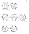
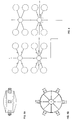
- the stator 1 consists of a box with a cylindrical chamber provided outside of six ( Figure 1) or eight ( Figures 2 and 3) fixed tubular connection flanges 4, forming part of the body of the box, or removable.
- the rotor 2 consists of a cylindrical piece which rotates in the stator 1 and provided with three (FIG. 1) or four (FIGS. 2 and 3) tubes 5; a right and two (Figure 1) or three ( Figures 2 and 3) tubes of curvature (angles) different, fixed or removable.
- the axes of the six flanges are distributed at a mutual interval of 60 °.
- T2 60 ° angle tube
- T3 120 ° angle tube
- the stator comprises in fact two additional flanges B6 and B7, at an angle of 90 ° with respect to the inlet flange A1.
- the stator has an input flange A1 and seven output flanges B1 - B7 (or 2 inputs, 6 outputs, etc.), or the opposite , and the axes of the eight flanges are distributed at a mutual interval of 45 °.
- the position of the rotor shown in the first diagram of Figure 1 allows the passage of A1 to B1 or B1 to A1 via the tube T1.
- the rotation of the rotor connects A1 with B4 or A1 with B5, via the tube T2 (positions 2 and 3), or A1 with B2 or A1 with B3, via the tube T3 (positions 4 and 5).
- T2 would connect B1 with B3 (positions 4) or B2 (position 7), and T3 would link B1 with B5 (position 2) and B4 (position not shown), which allows to obtain a reversible system.
- the set also allows, for example, a simultaneous connection B1 / B5 (via T3), when connecting A1 / B4 (via T2), as illustrated by position 2.
- Other similar simultaneous connections or connections alternatives can easily be imagined from Figure 1.
- the eight-flange assembly allows simultaneous connections similar to those of the six-flange switch described above, some additional simultaneous connections, and some alternative connections (such as positions 8 and 9), which deduce easily from Figure 2.
- the connections from A1 to B1 can be made via T1 (position 1), from A1 to B6 and B7, via T4 (positions 2 and 3), from A1 to B4 and B5, via T5 (positions 4 and 5), from A1 to B2 and B3 via T6 (positions 7 and 6). It is also possible to make the connections from B1 to B6 or B7 (positions 5 and 7) via T4, to B2 (position 3) or B3 (position 11) via T5, or to B5 (position 2) or B4 (position not shown) via T6; connections B2 / B4 via T4 and B5 / B7 via T5 (position 6); etc., etc. Similarly, this set allows other similar or additional simultaneous connections and other alternative connections, which will be readily deduced from Figure 3 (such as positions 9, 10 and 11).
- Such a switch remains a seven-way switch from the A1 input, but greatly increases the possibility of reverse connections and simultaneous connections.
- a five-way switch can also be designed, comprising a stator with six flanges at radial positions of 0, 45, 135, 180, 225 and 315 ° and a rotor with 45 °, 135 ° curvature connection cavities. and 180 °, corresponding to a switch as shown in Figure 3, however without the outputs B6 and B7 and without the tube T4; it goes without saying that in such a realization tubes T5 and T6 can also be arranged on each side of the right tube T1 (as for the tubes T2 and T3 of the five-way switch, shown in Figure 1).
Landscapes
- Engineering & Computer Science (AREA)
- Mechanical Engineering (AREA)
- Multiple-Way Valves (AREA)
- Branching, Merging, And Special Transfer Between Conveyors (AREA)
- Attitude Control For Articles On Conveyors (AREA)
- General Details Of Gearings (AREA)
Claims (2)
- Verzweigung für den pneumatischen Rohrtransport oder den Rohrtransport von Flüssigkeiten, mit einem zylindrischen Körper, der für einen Stator (1) dient, der mindestens sechs Rohranschlüsse und einen Rotor (2) aufweist, der mindestens drei Anschlussöffnungen (5) umfasst, die unterschiedliche Rundungen aufweisen, wodurch eine selektive Verbindung von zwei Rohranschlüssen (4) des Stators ermöglicht wird, der sich dadurch auszeichnet, dass er eine selektive und umkehrbare Mehrweg-Verzweigung ermöglicht, ausgehend von einem Rohranschluss (A1) zu mindestens fünf unterschiedlichen Rohranschlüssen (B1-B5 ; B1-B7) dank der Zufügung eines Stators (1), der mit Rohranschlüssen versehen ist, die radial und symmetrisch gegenüber einer Achse des besagten zylindrischen Körpers angebracht sind, und eines Rotors (2), je nach einer der folgenden Alternativen:ein Stator (1) mit sechs Rohranschlüssen (4), die in einem gegenseitigen Radialabstand von 60° angebracht sind, und ein Rotor (2) mit Anschlussöffnungen (5) in Rundungen von 60°, 120° und 180° (rechte Öffnung);ein Stator (1) mit acht Rohranschlüssen (4), die in einem gegenseitigen Radialabstand von 45° angebracht sind, und ein Rotor (2) mit Anschlussöffnungen (5) in Rundungen von 45°, 90°, 135° und 180° (rechte Öffnung);ein Stator (1) mit acht Rohranschlüssen (4), von denen zwei in einem gegenseitigen Radialabstand von 180° und die anderen in einem Radialabstand von 60°, 90° bzw. 120° der ersten angesiedelt sind,und ein Rotor (2), der Anschlussöffnungen (5) in Rundungen von 60°, 90°, 120° und 180° (rechte Öffnung) aufweist.
- Verzweigungsmethode für den pneumatischen Rohrtransport oder den Rohrtransport von Flüssigkeiten, wobei ein Rotor (2) verlagert wird, der mehrere Anschlussöffnungen (5) umfasst, die unterschiedliche Rundungen aufweisen, gegenüber einem zylindrischen Körper, der für einen Stator (1) dient, der mit mehreren Rohranschlüssen (4) versehen ist und sich dadurch auszeichnet, dass er eine selektive und umkehrbare Mehrweg-Verzweigung ermöglicht, ausgehend von einem Rohranschluss (A1) zu mindestens fünf unterschiedlichen Rohranschlüssen (B1-B5, B1-B7) dank der Zufügung eines Stators (1), der mit Rohranschlüssen versehen ist, die radial und symmetrisch gegenüber einer Achse des besagten zylindrischen Körpers und des Rotors (2) angesiedelt sind, unter Verbindung
von Rohranschlüssen (4), die gegenseitig in 60° von Anschlussöffnungen (5) mit Rundungen von 60°, 120° und 180° (rechte Öffnung) angebracht sind;
von Rohranschlüssen (4), die gegenseitig in 45° von Anschlussöffnungen (5) mit Rundungen von 45°, 90°, 135° und 180° angebracht sind; oder
von Rohranschlüssen, die gegenseitig in 60° und 90° von Anschlussöffnungen (5) mit Rundungen von 60°, 90°, 120° und 180° angebracht sind.
Applications Claiming Priority (3)
| Application Number | Priority Date | Filing Date | Title |
|---|---|---|---|
| BE200300022 | 2003-01-10 | ||
| BE2003/0022A BE1015301A4 (fr) | 2003-01-10 | 2003-01-10 | Aiguillage de transport tubulaire et corps cylindrique destine a un tel aiguillage. |
| PCT/BE2004/000001 WO2004063063A1 (fr) | 2003-01-10 | 2004-01-08 | Aiguillages de transport tubulaire et methode d’aiguillage pour transport tubulaire |
Publications (2)
| Publication Number | Publication Date |
|---|---|
| EP1590280A1 EP1590280A1 (de) | 2005-11-02 |
| EP1590280B1 true EP1590280B1 (de) | 2007-07-18 |
Family
ID=32686679
Family Applications (1)
| Application Number | Title | Priority Date | Filing Date |
|---|---|---|---|
| EP04700657A Expired - Lifetime EP1590280B1 (de) | 2003-01-10 | 2004-01-08 | Förderleitungsweichen und schaltverfahren für förderleitungen |
Country Status (5)
| Country | Link |
|---|---|
| EP (1) | EP1590280B1 (de) |
| AT (1) | ATE367343T1 (de) |
| BE (1) | BE1015301A4 (de) |
| DE (1) | DE602004007622T2 (de) |
| WO (1) | WO2004063063A1 (de) |
Cited By (1)
| Publication number | Priority date | Publication date | Assignee | Title |
|---|---|---|---|---|
| EP4357276A1 (de) * | 2022-10-17 | 2024-04-24 | Werner Koch | Weiche für eine einrichtung zur förderung und/oder zum transport von materialien |
Families Citing this family (4)
| Publication number | Priority date | Publication date | Assignee | Title |
|---|---|---|---|---|
| EP2272779A1 (de) * | 2005-05-31 | 2011-01-12 | I.S.T. Industrie Service Technologie Beratungs-und Beteiligungsgesellschaft mbH | Molchbare Verteilervorrichtung |
| US20100071790A1 (en) * | 2006-12-12 | 2010-03-25 | Cameron International Corporation | Diverter valve |
| DE102009057650A1 (de) * | 2009-12-09 | 2011-06-16 | GESRA Gerätebau GmbH | Förderrohrweiche |
| CN103050759B (zh) * | 2013-01-31 | 2015-03-11 | 成都赛纳赛德科技有限公司 | 倒π型五端口E面功分器 |
Family Cites Families (6)
| Publication number | Priority date | Publication date | Assignee | Title |
|---|---|---|---|---|
| FR501088A (fr) * | 1918-10-03 | 1920-04-01 | Quigley Furnace Specialties Co | Appareil pour la manipulation de matières pulvérulentes, et plus particulièrement de charbon pulvérisé, au moyen d'air comprimé |
| US2991803A (en) * | 1956-08-31 | 1961-07-11 | Southern Welding & Machine Com | Diverter valves |
| US3826539A (en) | 1972-10-10 | 1974-07-30 | Pennsylvania Engineering Corp | Method and apparatus for directional switching of pneumatic material transport piping |
| DE4028582A1 (de) * | 1990-09-08 | 1992-03-12 | Motan Verfahrenstechnik | Rohrweiche |
| DE19521301A1 (de) | 1995-06-12 | 1996-12-19 | Kochalski Ilse | Rohrweiche |
| DE29710193U1 (de) | 1997-06-11 | 1997-08-14 | Bureck + Erlenkötter Maschinenfabrik GmbH, 59269 Beckum | Verteilerweiche |
-
2003
- 2003-01-10 BE BE2003/0022A patent/BE1015301A4/fr not_active IP Right Cessation
-
2004
- 2004-01-08 EP EP04700657A patent/EP1590280B1/de not_active Expired - Lifetime
- 2004-01-08 DE DE602004007622T patent/DE602004007622T2/de not_active Expired - Lifetime
- 2004-01-08 AT AT04700657T patent/ATE367343T1/de not_active IP Right Cessation
- 2004-01-08 WO PCT/BE2004/000001 patent/WO2004063063A1/fr not_active Ceased
Cited By (1)
| Publication number | Priority date | Publication date | Assignee | Title |
|---|---|---|---|---|
| EP4357276A1 (de) * | 2022-10-17 | 2024-04-24 | Werner Koch | Weiche für eine einrichtung zur förderung und/oder zum transport von materialien |
Also Published As
| Publication number | Publication date |
|---|---|
| BE1015301A4 (fr) | 2005-01-11 |
| ATE367343T1 (de) | 2007-08-15 |
| DE602004007622T2 (de) | 2008-06-05 |
| DE602004007622D1 (de) | 2007-08-30 |
| WO2004063063A1 (fr) | 2004-07-29 |
| EP1590280A1 (de) | 2005-11-02 |
Similar Documents
| Publication | Publication Date | Title |
|---|---|---|
| BE1009200A4 (fr) | Bride pour tube ou manchon compensateur. | |
| EP0907848B1 (de) | Mehrwegeventil für einen wärmetauscher | |
| FR2730423A1 (fr) | Agencement d'une grille de retenue d'un materiau actif dans un recipient, et recipient ainsi equipe | |
| EP0321346A1 (de) | Mit Gewinde vesehener Gegenstand, z.B. eine Schraube, und Verbindung von Teilen mit Hilfe dieses Gegenstands | |
| BE1015301A4 (fr) | Aiguillage de transport tubulaire et corps cylindrique destine a un tel aiguillage. | |
| EP0504032B1 (de) | Redundant Schlussventil | |
| JP3542947B2 (ja) | ユニットフレームと流量計測メーターユニット | |
| FR2945101A1 (fr) | Nourrice de distribution ou de collecte de fluide et installation de moulage comprenant une telle nourrice | |
| FR2559561A1 (fr) | Douille a bride en poudre de metal frittee pour monter un organe d'une machine sur un arbre | |
| EP0284494B1 (de) | Verbindungsvorrichtung für Bauholzteile | |
| FR2736429A1 (fr) | Dispositif de mesure de fluide et systeme comprenant plusieurs dispositifs de ce type | |
| EP0027765B1 (de) | Kugelhahn und Verfahren zu dessen Herstellung | |
| FR2834751A1 (fr) | Amenagement de rotor d'une turbomachine | |
| EP1165413B1 (de) | Kugelhahn zur steuerung des durchflusses pulverischer oder körniger produkte | |
| EP2476915B1 (de) | Bypass und Stromteiler mit Aufteilung in drei oder vier Abzweigungen für den hydraulischen Einsatz | |
| EP0335307B1 (de) | Numerisches Ventil | |
| FR2587429A1 (fr) | Cale hydroelastique a au moins deux directions d'amortissement | |
| FR2677731A1 (fr) | Plaque de raccordement a valve a action progressive de construction modulaire, en particulier pour des fluides pneumatiques. | |
| FR2842297A1 (fr) | Compteur volumetrique fluide | |
| FR2482240A1 (fr) | Vanne a diaphragme | |
| KR102080669B1 (ko) | 가스 파이프라인용 스위블 유니온 | |
| FR2848281A1 (fr) | Robinet a boisseau | |
| WO1990010791A1 (fr) | Pompe peristaltique | |
| FR2563602A1 (fr) | Dispositif de reglage de debit d'un fluide tel que l'eau dans une canalisation | |
| CN105080195B (zh) | 具有轴向进、出水接口的水路切换器及净水机 |
Legal Events
| Date | Code | Title | Description |
|---|---|---|---|
| PUAI | Public reference made under article 153(3) epc to a published international application that has entered the european phase |
Free format text: ORIGINAL CODE: 0009012 |
|
| 17P | Request for examination filed |
Effective date: 20050727 |
|
| AK | Designated contracting states |
Kind code of ref document: A1 Designated state(s): AT BE BG CH CY CZ DE DK EE ES FI FR GB GR HU IE IT LI LU MC NL PT RO SE SI SK TR |
|
| AX | Request for extension of the european patent |
Extension state: AL LT LV MK |
|
| DAX | Request for extension of the european patent (deleted) | ||
| GRAP | Despatch of communication of intention to grant a patent |
Free format text: ORIGINAL CODE: EPIDOSNIGR1 |
|
| GRAS | Grant fee paid |
Free format text: ORIGINAL CODE: EPIDOSNIGR3 |
|
| GRAA | (expected) grant |
Free format text: ORIGINAL CODE: 0009210 |
|
| AK | Designated contracting states |
Kind code of ref document: B1 Designated state(s): AT BE BG CH CY CZ DE DK EE ES FI FR GB GR HU IE IT LI LU MC NL PT RO SE SI SK TR |
|
| REG | Reference to a national code |
Ref country code: GB Ref legal event code: FG4D Free format text: NOT ENGLISH |
|
| REG | Reference to a national code |
Ref country code: CH Ref legal event code: EP |
|
| REF | Corresponds to: |
Ref document number: 602004007622 Country of ref document: DE Date of ref document: 20070830 Kind code of ref document: P |
|
| REG | Reference to a national code |
Ref country code: IE Ref legal event code: FG4D Free format text: LANGUAGE OF EP DOCUMENT: FRENCH |
|
| GBT | Gb: translation of ep patent filed (gb section 77(6)(a)/1977) |
Effective date: 20071017 |
|
| PG25 | Lapsed in a contracting state [announced via postgrant information from national office to epo] |
Ref country code: ES Free format text: LAPSE BECAUSE OF FAILURE TO SUBMIT A TRANSLATION OF THE DESCRIPTION OR TO PAY THE FEE WITHIN THE PRESCRIBED TIME-LIMIT Effective date: 20071029 Ref country code: BG Free format text: LAPSE BECAUSE OF FAILURE TO SUBMIT A TRANSLATION OF THE DESCRIPTION OR TO PAY THE FEE WITHIN THE PRESCRIBED TIME-LIMIT Effective date: 20071018 Ref country code: FI Free format text: LAPSE BECAUSE OF FAILURE TO SUBMIT A TRANSLATION OF THE DESCRIPTION OR TO PAY THE FEE WITHIN THE PRESCRIBED TIME-LIMIT Effective date: 20070718 Ref country code: PT Free format text: LAPSE BECAUSE OF FAILURE TO SUBMIT A TRANSLATION OF THE DESCRIPTION OR TO PAY THE FEE WITHIN THE PRESCRIBED TIME-LIMIT Effective date: 20071218 |
|
| PG25 | Lapsed in a contracting state [announced via postgrant information from national office to epo] |
Ref country code: AT Free format text: LAPSE BECAUSE OF FAILURE TO SUBMIT A TRANSLATION OF THE DESCRIPTION OR TO PAY THE FEE WITHIN THE PRESCRIBED TIME-LIMIT Effective date: 20070718 |
|
| REG | Reference to a national code |
Ref country code: IE Ref legal event code: FD4D |
|
| PG25 | Lapsed in a contracting state [announced via postgrant information from national office to epo] |
Ref country code: GR Free format text: LAPSE BECAUSE OF FAILURE TO SUBMIT A TRANSLATION OF THE DESCRIPTION OR TO PAY THE FEE WITHIN THE PRESCRIBED TIME-LIMIT Effective date: 20071019 Ref country code: DK Free format text: LAPSE BECAUSE OF FAILURE TO SUBMIT A TRANSLATION OF THE DESCRIPTION OR TO PAY THE FEE WITHIN THE PRESCRIBED TIME-LIMIT Effective date: 20070718 |
|
| PLBE | No opposition filed within time limit |
Free format text: ORIGINAL CODE: 0009261 |
|
| STAA | Information on the status of an ep patent application or granted ep patent |
Free format text: STATUS: NO OPPOSITION FILED WITHIN TIME LIMIT |
|
| PG25 | Lapsed in a contracting state [announced via postgrant information from national office to epo] |
Ref country code: IE Free format text: LAPSE BECAUSE OF FAILURE TO SUBMIT A TRANSLATION OF THE DESCRIPTION OR TO PAY THE FEE WITHIN THE PRESCRIBED TIME-LIMIT Effective date: 20070718 Ref country code: SK Free format text: LAPSE BECAUSE OF FAILURE TO SUBMIT A TRANSLATION OF THE DESCRIPTION OR TO PAY THE FEE WITHIN THE PRESCRIBED TIME-LIMIT Effective date: 20070718 Ref country code: CZ Free format text: LAPSE BECAUSE OF FAILURE TO SUBMIT A TRANSLATION OF THE DESCRIPTION OR TO PAY THE FEE WITHIN THE PRESCRIBED TIME-LIMIT Effective date: 20070718 |
|
| 26N | No opposition filed |
Effective date: 20080421 |
|
| PG25 | Lapsed in a contracting state [announced via postgrant information from national office to epo] |
Ref country code: RO Free format text: LAPSE BECAUSE OF FAILURE TO SUBMIT A TRANSLATION OF THE DESCRIPTION OR TO PAY THE FEE WITHIN THE PRESCRIBED TIME-LIMIT Effective date: 20070718 Ref country code: SE Free format text: LAPSE BECAUSE OF FAILURE TO SUBMIT A TRANSLATION OF THE DESCRIPTION OR TO PAY THE FEE WITHIN THE PRESCRIBED TIME-LIMIT Effective date: 20071018 |
|
| PG25 | Lapsed in a contracting state [announced via postgrant information from national office to epo] |
Ref country code: MC Free format text: LAPSE BECAUSE OF NON-PAYMENT OF DUE FEES Effective date: 20080131 |
|
| REG | Reference to a national code |
Ref country code: CH Ref legal event code: PL |
|
| PG25 | Lapsed in a contracting state [announced via postgrant information from national office to epo] |
Ref country code: LI Free format text: LAPSE BECAUSE OF NON-PAYMENT OF DUE FEES Effective date: 20080131 Ref country code: CH Free format text: LAPSE BECAUSE OF NON-PAYMENT OF DUE FEES Effective date: 20080131 |
|
| PG25 | Lapsed in a contracting state [announced via postgrant information from national office to epo] |
Ref country code: EE Free format text: LAPSE BECAUSE OF FAILURE TO SUBMIT A TRANSLATION OF THE DESCRIPTION OR TO PAY THE FEE WITHIN THE PRESCRIBED TIME-LIMIT Effective date: 20070718 |
|
| PG25 | Lapsed in a contracting state [announced via postgrant information from national office to epo] |
Ref country code: SI Free format text: LAPSE BECAUSE OF FAILURE TO SUBMIT A TRANSLATION OF THE DESCRIPTION OR TO PAY THE FEE WITHIN THE PRESCRIBED TIME-LIMIT Effective date: 20070718 |
|
| PG25 | Lapsed in a contracting state [announced via postgrant information from national office to epo] |
Ref country code: CY Free format text: LAPSE BECAUSE OF FAILURE TO SUBMIT A TRANSLATION OF THE DESCRIPTION OR TO PAY THE FEE WITHIN THE PRESCRIBED TIME-LIMIT Effective date: 20070718 |
|
| PGFP | Annual fee paid to national office [announced via postgrant information from national office to epo] |
Ref country code: FR Payment date: 20100107 Year of fee payment: 7 |
|
| PGFP | Annual fee paid to national office [announced via postgrant information from national office to epo] |
Ref country code: IT Payment date: 20100123 Year of fee payment: 7 |
|
| PGFP | Annual fee paid to national office [announced via postgrant information from national office to epo] |
Ref country code: BE Payment date: 20091221 Year of fee payment: 7 Ref country code: DE Payment date: 20100121 Year of fee payment: 7 Ref country code: GB Payment date: 20100121 Year of fee payment: 7 |
|
| PG25 | Lapsed in a contracting state [announced via postgrant information from national office to epo] |
Ref country code: HU Free format text: LAPSE BECAUSE OF FAILURE TO SUBMIT A TRANSLATION OF THE DESCRIPTION OR TO PAY THE FEE WITHIN THE PRESCRIBED TIME-LIMIT Effective date: 20080119 Ref country code: LU Free format text: LAPSE BECAUSE OF NON-PAYMENT OF DUE FEES Effective date: 20080108 |
|
| PG25 | Lapsed in a contracting state [announced via postgrant information from national office to epo] |
Ref country code: TR Free format text: LAPSE BECAUSE OF FAILURE TO SUBMIT A TRANSLATION OF THE DESCRIPTION OR TO PAY THE FEE WITHIN THE PRESCRIBED TIME-LIMIT Effective date: 20070718 |
|
| PGFP | Annual fee paid to national office [announced via postgrant information from national office to epo] |
Ref country code: NL Payment date: 20091224 Year of fee payment: 7 |
|
| BERE | Be: lapsed |
Owner name: AUBRY, MICHEL Effective date: 20110131 |
|
| REG | Reference to a national code |
Ref country code: NL Ref legal event code: V1 Effective date: 20110801 |
|
| GBPC | Gb: european patent ceased through non-payment of renewal fee |
Effective date: 20110108 |
|
| REG | Reference to a national code |
Ref country code: FR Ref legal event code: ST Effective date: 20110930 |
|
| PG25 | Lapsed in a contracting state [announced via postgrant information from national office to epo] |
Ref country code: FR Free format text: LAPSE BECAUSE OF NON-PAYMENT OF DUE FEES Effective date: 20110131 |
|
| PG25 | Lapsed in a contracting state [announced via postgrant information from national office to epo] |
Ref country code: BE Free format text: LAPSE BECAUSE OF NON-PAYMENT OF DUE FEES Effective date: 20110131 Ref country code: GB Free format text: LAPSE BECAUSE OF NON-PAYMENT OF DUE FEES Effective date: 20110108 |
|
| REG | Reference to a national code |
Ref country code: DE Ref legal event code: R119 Ref document number: 602004007622 Country of ref document: DE Effective date: 20110802 |
|
| PG25 | Lapsed in a contracting state [announced via postgrant information from national office to epo] |
Ref country code: IT Free format text: LAPSE BECAUSE OF NON-PAYMENT OF DUE FEES Effective date: 20110108 Ref country code: NL Free format text: LAPSE BECAUSE OF NON-PAYMENT OF DUE FEES Effective date: 20110801 |
|
| PG25 | Lapsed in a contracting state [announced via postgrant information from national office to epo] |
Ref country code: DE Free format text: LAPSE BECAUSE OF NON-PAYMENT OF DUE FEES Effective date: 20110802 |