EP0504032B1 - Redundant Schlussventil - Google Patents
Redundant Schlussventil Download PDFInfo
- Publication number
- EP0504032B1 EP0504032B1 EP92400610A EP92400610A EP0504032B1 EP 0504032 B1 EP0504032 B1 EP 0504032B1 EP 92400610 A EP92400610 A EP 92400610A EP 92400610 A EP92400610 A EP 92400610A EP 0504032 B1 EP0504032 B1 EP 0504032B1
- Authority
- EP
- European Patent Office
- Prior art keywords
- valve
- sealing device
- valve member
- retractable
- valve according
- Prior art date
- Legal status (The legal status is an assumption and is not a legal conclusion. Google has not performed a legal analysis and makes no representation as to the accuracy of the status listed.)
- Expired - Lifetime
Links
Images


Classifications
-
- F—MECHANICAL ENGINEERING; LIGHTING; HEATING; WEAPONS; BLASTING
- F16—ENGINEERING ELEMENTS AND UNITS; GENERAL MEASURES FOR PRODUCING AND MAINTAINING EFFECTIVE FUNCTIONING OF MACHINES OR INSTALLATIONS; THERMAL INSULATION IN GENERAL
- F16K—VALVES; TAPS; COCKS; ACTUATING-FLOATS; DEVICES FOR VENTING OR AERATING
- F16K5/00—Plug valves; Taps or cocks comprising only cut-off apparatus having at least one of the sealing faces shaped as a more or less complete surface of a solid of revolution, the opening and closing movement being predominantly rotary
- F16K5/06—Plug valves; Taps or cocks comprising only cut-off apparatus having at least one of the sealing faces shaped as a more or less complete surface of a solid of revolution, the opening and closing movement being predominantly rotary with plugs having spherical surfaces; Packings therefor
- F16K5/0605—Plug valves; Taps or cocks comprising only cut-off apparatus having at least one of the sealing faces shaped as a more or less complete surface of a solid of revolution, the opening and closing movement being predominantly rotary with plugs having spherical surfaces; Packings therefor with particular plug arrangements, e.g. particular shape or built-in means
-
- F—MECHANICAL ENGINEERING; LIGHTING; HEATING; WEAPONS; BLASTING
- F16—ENGINEERING ELEMENTS AND UNITS; GENERAL MEASURES FOR PRODUCING AND MAINTAINING EFFECTIVE FUNCTIONING OF MACHINES OR INSTALLATIONS; THERMAL INSULATION IN GENERAL
- F16K—VALVES; TAPS; COCKS; ACTUATING-FLOATS; DEVICES FOR VENTING OR AERATING
- F16K35/00—Means to prevent accidental or unauthorised actuation
- F16K35/14—Means to prevent accidental or unauthorised actuation interlocking two or more valves
-
- Y—GENERAL TAGGING OF NEW TECHNOLOGICAL DEVELOPMENTS; GENERAL TAGGING OF CROSS-SECTIONAL TECHNOLOGIES SPANNING OVER SEVERAL SECTIONS OF THE IPC; TECHNICAL SUBJECTS COVERED BY FORMER USPC CROSS-REFERENCE ART COLLECTIONS [XRACs] AND DIGESTS
- Y10—TECHNICAL SUBJECTS COVERED BY FORMER USPC
- Y10T—TECHNICAL SUBJECTS COVERED BY FORMER US CLASSIFICATION
- Y10T137/00—Fluid handling
- Y10T137/8593—Systems
- Y10T137/87096—Valves with separate, correlated, actuators
- Y10T137/87121—Coaxial stems
- Y10T137/87129—Rotary
-
- Y—GENERAL TAGGING OF NEW TECHNOLOGICAL DEVELOPMENTS; GENERAL TAGGING OF CROSS-SECTIONAL TECHNOLOGIES SPANNING OVER SEVERAL SECTIONS OF THE IPC; TECHNICAL SUBJECTS COVERED BY FORMER USPC CROSS-REFERENCE ART COLLECTIONS [XRACs] AND DIGESTS
- Y10—TECHNICAL SUBJECTS COVERED BY FORMER USPC
- Y10T—TECHNICAL SUBJECTS COVERED BY FORMER US CLASSIFICATION
- Y10T137/00—Fluid handling
- Y10T137/8593—Systems
- Y10T137/87265—Dividing into parallel flow paths with recombining
- Y10T137/87298—Having digital flow controller
-
- Y—GENERAL TAGGING OF NEW TECHNOLOGICAL DEVELOPMENTS; GENERAL TAGGING OF CROSS-SECTIONAL TECHNOLOGIES SPANNING OVER SEVERAL SECTIONS OF THE IPC; TECHNICAL SUBJECTS COVERED BY FORMER USPC CROSS-REFERENCE ART COLLECTIONS [XRACs] AND DIGESTS
- Y10—TECHNICAL SUBJECTS COVERED BY FORMER USPC
- Y10T—TECHNICAL SUBJECTS COVERED BY FORMER US CLASSIFICATION
- Y10T137/00—Fluid handling
- Y10T137/8593—Systems
- Y10T137/87917—Flow path with serial valves and/or closures
- Y10T137/88062—Coaxial oppositely directed seats
Definitions
- the present invention relates to a redundant valve on closing, that is to say a valve in which the probabilities of accidental opening or non-closing of the valve are significantly less than the probability of non-response to an opening command.
- a redundant valve on closing that is to say a valve in which the probabilities of accidental opening or non-closing of the valve are significantly less than the probability of non-response to an opening command.
- which must itself be very small and which can be used in various fields such as in particular the nuclear industry, the chemistry of toxic or corrosive products, the space field and aeronautics. If we take for example the case of supplying an installation with a dangerous fluid, the risks associated with a valve not closing in the event of a leak in the installation, are significantly greater than those associated with not response to a command to open this same valve, which results in a simple delay in commissioning.
- the large size constituted by such an assembly of two valves is a drawback to which is added that of a mass twice that of a single valve.
- the presence of two valves requires a more complex assembly than in the case of a single valve and therefore increases the cost of the installation.
- the entire system includes four valve bodies, which leads to excessive bulk and complexity.
- the object of the invention is therefore essentially to remedy the aforementioned drawbacks and to be able to meet the required security requirements while reducing the bulk, the mass and the assembly cost.
- the object of the invention is also to produce a single valve whose use is simplified.
- the present invention also relates to a valve whose sealing system is arranged in such a way that it does not allow the confinement of certain volumes of liquid conveyed inside the valve body, and moreover limits friction, thus reducing the wear of the sealing means.
- a redundant valve at closure comprising a single valve body, first and second plugs arranged inside said valve body, and each comprising an orifice allowing the passage of fluid, first and second means independent driving in rotation of the first and second bushels and a first sealing device cooperating with one of the first and second bushels, characterized in that the first and second bushels are both hollow, substantially hemispherical, nested one in the other and have different diameters, and in that it comprises first and second sealing devices each comprising at least one annular seal and associated respectively with the first and second bushels.
- the redundant closing valve according to the invention by the presence of a single valve body containing two concentric hollow plugs, of different sizes and nested, controlled by two independent actuators, ensures redundancy when closing the valve by making two independent seals, without the need to couple two separate valves in series, which contributes to greatly reducing the mass, size and complexity of the assembly, these advantages being particularly important, especially in space or aeronautics where the mass or volume on board must be as small as possible.
- valve with corrosive or toxic cryogenic fluids means that the fluid must not be confined inside the valve.
- the first and second sealing devices are retractable and are connected by at least one spacer disposed inside the first and second bushels, so that when one of the first and second devices seal is open, the other seal is closed.
- the retraction means of the retractable sealing device cooperating with the first plug arranged upstream are controlled directly or indirectly by the position of this first plug cooperating with this sealing device.
- the retraction means of the retractable sealing device cooperating with the first plug may comprise a cam whose position is defined by the position of this first plug cooperating with this sealing device, the profile of the cam being such that the closure of the first bushel causes that of this device sealing while the opening of the first plug causes that of this sealing device.
- the retraction means of the retractable sealing device cooperating with the second plug arranged downstream are controlled directly or indirectly by the position of this second plug cooperating with this sealing device.
- the retraction means of the retractable sealing device cooperating with the second bushel may comprise a cam whose position is defined by the position of this second bushel cooperating with this sealing device, the profile of the cams being such that the closing of the second plug causes that of this sealing device while the opening of the second plug causes that of this sealing device.
- one of the sealing devices is not retractable, and comprises a seal consisting of a lip seal, while the other of the first and second sealing devices is retractable, and means for retracting this retractable sealing device are provided to avoid the confinement of fluid inside the valve.
- the retractable sealing device is located in the vicinity of the first plug arranged on the upstream side and is controlled as a function of the position of the second plug arranged on the downstream side so that said device the retractable seal is in the closed position when the second plug is open and vice versa.
- valve may include a cam integral with the second plug to control the retraction of the retractable sealing device located in the vicinity of the first plug.
- the retractable sealing device is located in the vicinity of the second plug arranged on the downstream side and is controlled as a function of the position of the first plug arranged on the upstream side so that said retractable sealing device is in the closed position when the first plug is open and vice versa.
- the valve may include a cam integral with the first plug to control the retraction of the retractable sealing device located in the vicinity of the second plug.
- the device retraction control sealing can be effected by a command by specific actuators not receiving their energy from one or the other of the plugs, such as mechanical, hydraulic, pneumatic, electric or pyrotechnic control means.
- Such actuators can be included in the valve.
- One or more pressure sensors may be provided in sections of the inlet or outlet pipe of the valve, near the plugs, to control the control of the retraction of the sealing devices.
- the control of the retraction of the sealing devices can also be controlled by plug position sensors.
- the sensors can be controlled by any member integral with the rotating assembly, comprising plug, shaft and rotor of a control device.
- the sealing devices whether or not they are retractable to avoid confinement, can temporarily, at least during the rotation of the plugs, undergo detachment, c 'is to say be slightly apart to no longer be in contact with the plugs with which they cooperate.
- the means used to order the detachments may or may not be confused with the means used to control the greater retraction of the joints intended to avoid containment.
- the axes of rotation of the first and second bushels can be combined, although the rotation drive means are themselves independent, or separate, which can further improve reliability by the independence of the axes of movement.
- the first and second means for driving the first and second plugs in rotation may be located on the same side of the valve body or on two diametrically opposite sides of the valve body.
- the valve may include sections of fluid inlet and outlet pipe which are coaxial or have different directions.
- the valve comprises a control device triggering the closing command of one of the first and second bushels with a predetermined delay with respect to the closing command of the other bushel, and provided that the non-closing of this other bushel was detected at the end of this predetermined delay.
- the mechanical resistance of the bushels can be increased to allow operation under high pressure, either by the use of massive bushels, of large thickness, or by the use of stiffeners or more particularly, interwoven stiffeners constituting a boxing.
- the invention also relates to a completely redundant device, on closing as well as on opening, for controlling the passage of fluid in a main pipe, this device comprising the insertion, in the circuit of said main pipe, of a circuit comprising two branches in parallel each equipped with a redundant valve on closing.
- FIG. 1 An example of a valve according to the invention, shown in FIG. 1, comprises a body 1 provided with a spherical cavity 2 into which open an upstream pipe 3 for fluid inlet and a downstream pipe 4 for fluid outlet.
- the two pipes 3 and 4 are coaxial and have identical shapes and dimensions.
- the plug 5 comprises a spherical central zone 8 extended by two flattened opposite and parallel zones 9 and 10.
- the spherical zone 8 comprises an orifice 11 (FIG. 2) of shape and dimension identical to those of the pipe 3.
- the flattened zone 9 comprises a pin 12 mounted rotating around the axis 7 by means of a ball bearing 13 on a support 14 secured to the body 1.
- the opposite flattened zone 10 comprises an axis 15 mounted rotating around the axis 7 by by means of a sealed bearing 16 mounted directly on the body 1.
- the axis 15 carries at its end a control device 17 of appropriate shape and dimensions.
- the control device 17 of the plug 5 can be constituted by any known type of automatic control device, mechanical, hydraulic or electric.
- the plug 6 comprises a spherical area 18 extended by a flattened area 19.
- the spherical area 18, which has a larger diameter than that of the spherical area 8 of the plug 5 so as to be able to pivot in an area external to that of the plug 5 , thus nested in the plug 6, has an orifice 20 (FIG. 2) of shape and dimensions identical to those of the pipe 4.
- the flattened area 19 is mounted to rotate about the axis 7 by means of a bearing 21 on an extension 22 of the body 1.
- the plug 6 has at its end diametrically opposite the flattened area 19, an axis 23 mounted rotating around the axis 7 by means of a sealed bearing 24 on the body 1.
- the axis 23 carries at its end a control device 25 of similar suitable configuration to device 17.
- the control device 25 of the plug 6 can thus also consist of any known type of automatic control device, mechanical, hydraulic or electric.
- This pipe section 26 is integral with the body 1 via the support 14 and the extension 22
- This pipe section 26 is intended to ensure the continuity of the fluid stream when the valve is open.
- the valve 5 cooperates with a seal 27 which can for example be a lip seal.
- the seal 27 is fixed to a sleeve-shaped seal holder 28 slidably mounted in a groove 29 in the wall 30 of the pipe 3.
- a bellows 31 fixed at one of its ends to the wall 30 and to the other of its ends at the seal carrier 28 provides sealing.
- the assembly constituted by the seal holder 28 and the seal 27 forms the sealing device 32 associated with the plug 5.
- the plug 6 cooperates with a seal 33 which can for example be a lip seal.
- the seal 33 is fixed to a sleeve-shaped seal holder 34 mounted to slide in a groove 35 in the wall 36 of the pipe 4.
- a bellows 37 fixed at one of its ends to the wall 36 and to the other of its ends at the seal carrier 34 provides sealing.
- the assembly constituted by the seal holder 34 and the seal 33 forms the sealing device 38 associated with the plug 6.
- the diameter d of the plug 5 is less than the diameter D of the plug 6 ( Figure 2).
- the sealing devices 32 and 38 may include fixed friction seals.
- each seal 27,33 is subject to separation, that is to say is slightly spaced from the valve 5,6 with which it cooperates, during the rotation of this valve.
- This arrangement has the advantage of avoiding the friction of the seal 27, 33 on the plug 5, 6 in movement and therefore of limiting the wear of this seal 27, 33.
- a cam mounted on the axis of rotation of each of the two plugs controls the retraction of the sealing device 32, 38 during the rotation of the plug 5, 6 with which it is associated.
- the seals 27, 33 are constituted by fixed seals, these are applied to the corresponding plug 5.6 in its closed position, and possibly in its open position.
- the seals 27, 33 are designed so as to be retractable in order to avoid confinement of the fluid inside the valve, the seals 27, 33 are selectively brought into contact or not with the corresponding plugs like this will be explained below.
- valve according to the invention in a circuit for circulating cryogenic fluids means that this fluid must not be confined inside the valve. More precisely, in no case should a volume of fluid remain enclosed in the cavity 2 between the plugs 5 and 6 in the closed position without communication with one of the pipes 3 or 4.
- the upstream bushel closes, while the downstream bushel does not close.
- the upstream valve seal must be closed to seal the valve, i.e. it must be released to press on this upstream valve.
- the downstream valve seal can be opened or closed. There is no risk of containment, since the liquid contained in the valve is evacuated through the outlet pipe.
- the upstream valve does not close, while the downstream valve closes.
- the upstream valve seal can be opened or closed. There is no risk of containment, since the liquid contained in the valve is in continuity with that contained in the inlet pipe.
- downstream valve seal must be closed to seal the valve.
- the seal of the upstream plug is closed to seal the valve while the seal of the downstream plug is open, to ensure non-containment, by evacuating the contents of the valve in the outlet pipe.
- the upstream valve seal is open, to ensure non-confinement by continuity between the interior of the valve and the upstream pipe, while the downstream valve seal is closed to seal the valve.
- Non-confinement can thus be achieved in this third possible state of the valve either by continuity with the upstream pipe or by downstream evacuation.
- the choice of one or other of the variant embodiments depends on the fluid conveyed (nature, temperature, pressure of the gas being in the downstream pipeline in the closed valve position), and on the materials used to construct the valve.
- the control of the retraction of the sealing devices can be ensured by a command external to the valve, using actuators acting mechanically, hydraulically, electrically. or pyrotechnic and which are optionally controlled by position sensors of the components of the valve, pressure sensors arranged in the fluid lines in the vicinity of the plugs or from a control center receiving all the useful information on the system status.
- the system for controlling the retraction of the sealing devices is constituted by mechanical control means internal to the valve.
- mechanical control means internal to the valve In this case, four different configurations are possible.
- one of the joints is retractable while the other joint remains fixed (while however possibly being able to be slightly moved away from the corresponding plug during the rotation of the latter).
- downstream seal 33 is fixed and the downstream plug 6 controls the opening (by retraction) and closing movements (contact with the upstream plug 5) of the upstream seal 27 so that this upstream seal 27 is closed when the downstream plug 6 is open ( Figure 2) and that this upstream seal 27 is open when the downstream plug 6 is closed ( Figure 1).
- downstream plug 6 is the only one to be closed, the upstream plug 5 remaining open, the non-confinement is ensured by the upstream, as in the case of FIG. 1 where the two plugs 5, 6 are closed.
- the upstream plug 5 is the only one to be closed, the downstream plug 6 remaining open, non-confinement is ensured by the downstream.
- FIGS. 8 and 11 A second possible configuration to obtain, by an internal control at the valve, a selective retraction of one of the seals, while the other seal remains fixed (while possibly being non-friction, that is to say being slightly apart of the corresponding plug during the rotation of the latter) is illustrated in FIGS. 8 and 11.
- This configuration corresponds to the configuration previously described, but the roles of the seals and plugs upstream and downstream are reversed.
- the upstream seal 27 is fixed and the upstream valve 5 controls the downstream sealing device 38 comprising the downstream seal 33 so that this downstream seal 33 is closed when the upstream valve 5 is open and this downstream seal 33 is open when the upstream plug 5 is closed.
- the downstream plug 6 remaining open, non-confinement is ensured downstream, just as when the two plugs 5, 6 are closed.
- the downstream plug 6 is the only one to be closed, the upstream plug 5 remaining open, non-confinement is ensured by upstream.
- a cam (not shown) can be fixed on the axis of the downstream plug 6 for controlling the sealing device 32, which comprises the seal 27 associated with the other plug 5, the cam being locked such that when the downstream plug 6 closes, it controls the opening of the upstream seal 27.
- a cam (not shown) can be fixed on the axis of the upstream plug 5 for controlling the sealing device 38 which includes the seal 33 associated with the other plug 6, the cam being set in such a way so that when the upstream plug 5 closes, it controls the opening of the downstream seal 33.
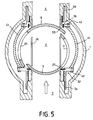
- an internal control at the valve aiming to prevent fluid confinement implements two retractable seals.
- the two upstream 32 and downstream 38 sealing devices are secured by a spacer 41, so that when the downstream seal 33 is open, the upstream seal 27 is closed and vice versa.
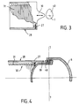
- the upstream valve 5 alone carries a cam 40 (FIGS. 3 and 4) which acts on a cam 39 integral with the upstream sealing device 32 to control the movements of the upstream seal 27.
- the profile of the cam 40 is such that the closure of the upstream plug causes that of the seal 27 and vice versa.
- a fourth possible configuration, illustrated in FIG. 12, is similar to the third configuration which has just been described, but with an inversion of the roles of the plugs and upstream and downstream joints.
- the two upstream 32 and downstream 38 sealing devices are also secured by a spacer 41, so that when the downstream seal 33 is open, the upstream seal 27 is closed and vice versa.
- the downstream plug 6 carries, alone, a cam, similar to the cam 40 of FIGS. 3 and 4, which acts on a cam, similar to the cam 39 of FIGS. 3 and 4, but integral with the downstream sealing device 38 for controlling displacements of the downstream seal 33.
- the profile of the cam is such that closing the downstream plug 6 causes that of the downstream seal 33 and vice versa.
- Figure 6 schematically shows another embodiment of the present invention.
- the axes of rotation of the two plugs nested one inside the other are not confused. This arrangement improves the reliability of the valve, the two axes of movement of the plugs being completely independent.
- Figure 7 schematically shows another embodiment of the present invention.
- the axes of rotation 71, 72 of the two plugs 5, 6 are also separate but this is not an obligation and these axes can also be confused.
- the fluid inlet and outlet lines 3, 4 are not coaxial or have different directions.
- the pipe section 26 has a shape adapted to ensure the continuity of the fluid stream.
- FIG. 7 there is also shown a pipe 3 for supplying fluid which is situated on the side of the valve 6 of large diameter while the pipe 4 for discharging the fluid is located on the side of the small diameter bushel 5.
- FIG. 8 represents an alternative embodiment of the present invention in which the two devices 17 and 25 for controlling the rotation of the valves 5, 6 are located on the same side of the valve and no longer diametrically opposite as was the case case in Figure 1.
- the axis 23 is in this case pierced by a bore 43 allowing the passage of the axis 15.
- the control devices 17 and 25 can control, independently of one another, the movements of the bushels 5 and 6.
- the control devices 17 and 25 of the plugs 5 and 6 shown in FIGS. 1, 8 and 11 can be constituted by any automatic control device, mechanical, hydraulic, pneumatic or electric.
- an active control device can be provided which triggers the command to close the plug 5 of small diameter with a certain delay in the only case where at the end of this predetermined delay, it was detected that the plug was not closed. nominal 6 of large diameter.
- the first and second bushels 5, 6 can be controlled so as to rotate in the same direction or in opposite directions, in a counter-rotating manner. Whether the bushels 5,6 are controlled synchronously or offset in time, it is however important that the control means 17 and 25 are independent so that we can always ensure the closure with any one of the bushels whatever the position of the other.
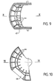
- the plug in accordance with the present invention shown in FIGS. 9 and 10 is designed to have increased mechanical resistance in the event of the valve operating in a circuit subjected to high pressures.
- Stiffeners 44 reinforce the body of the plug 45 provided with an opening 46. These stiffeners 44 if they intersect make it possible to produce a casing reinforcing the plug. It is also possible to provide a massive bushel of significant thickness having the same mechanical resistance to high pressures.
- FIG. 11 shows the parallel mounting of two redundant closing valves according to the invention.
Claims (26)
- Redundanz-Absperrventil mit einem einzigen Ventilgehäuse (1), einem ersten und zweiten Ventilküken (5, 6), die im Inneren des genannten Ventilgehäuses (1) angeordnet sind, von denen jedes eine Öffnung (11, 20) aufweist, die den Durchtritt des Strömungsmittels gestattet, ersten und zweiten unabhängigen Mitteln (17, 25) zum Drehantrieb des ersten und zweiten Kükens (5, 6) sowie einer ersten Abdichtvorrichtung, die mit dem ersten oder zweiten Küken (5, 6) zusammenwirkt, dadurch gekennzeichnet, daß das erste und zweite Küken (5, 6) alle beide hohl sind, im wesentlichen halbkugelig sind, ineinander verschachtelt sind und unterschiedliche Durchmesser aufweisen, und daß es eine erste und zweite Abdichtvorrichtung (32, 38) aufweist, die jeweils eine Ringdichtung (27, 33) aufweisen und dem ersten bzw. zweiten Küken (5, 6) zugeordnet sind.
- Ventil nach Anspruch 1, dadurch gekennzeichnet, daß es Mittel zum Abheben der ersten und zweiten Abdichtvorrichtung (32, 38) während der Drehung des ersten und zweiten Kükens (5, 6) aufweist.
- Ventil nach Anspruch 1, dadurch gekennzeichnet, daß eine der Abdichtvorrichtungen nicht zurückziehbar ist und eine Dichtung aufweist, die von einer Lippendichtung gebildet ist, während die andere der ersten und zweiten Abdichtvorrichtungen (32, 38) zurückziehbar ist, und daß Mittel (39, 40, 41) zum Zurückziehen dieser zurückziehbaren Abdichtvorrichtung vorgesehen sind, um das Einschließen von Strömungsmittel im Inneren des Ventiles zu vermeiden.
- Ventil nach Anspruch 3, dadurch gekennzeichnet, daß die zurückziehbare Abdichtvorrichtung (32) in der Nähe des ersten Kükens (5) gelegen ist, das auf der stromaufwärts gelegenen Seite angeordnet ist, und in Funktion der Lage des zweiten Kükens (6) gesteuert wird, das auf der stromabwärts gelegenen Seite angeordnet ist, und zwar derart, daß die genannte, zurückziehbare Abdichtvorrichtung (32) sich in geschlossener Lage befindet, wenn das zweite Küken (6) offen ist, und umgekehrt.
- Ventil nach Anspruch 4, dadurch gekennzeichnet, daß es einen Nocken aufweist, der fest bzw. einstückig mit dem zweiten Küken (6) verbunden ist, um das zurückziehen der zurückziehbaren Abdichtvorrichtung (32) zu steuern, die dem ersten Küken (5) benachbart angeordnet ist.
- Ventil nach Anspruch 3, dadurch gekennzeichnet, daß die zurückziehbare Abdichtvorrichtung (38) dem zweiten Küken (6) benachbart angeordnet ist, das auf der stromabwärts gelegenen Seite angeordnet ist, und in Funktion der Lage des ersten Kükens (5) gesteuert ist, das auf der stromaufwärts gelegenen Seite angeordnet ist, und zwar derart, daß die genannte, zurückziehbare Abdichtvorrichtung (38) sich in der geschlossenen Lage befindet, wenn das erste Küken (5) offen ist, und umgekehrt.
- Ventil nach Anspruch 6, dadurch gekennzeichnet, daß es einen mit dem ersten Küken (5) einstückig bzw. fest verbundenen Nocken aufweist, um das Zurückziehen der zurückziehbaren Abdichtvorrichtung (38) zu steuern, die dem zweiten Küken (6) benachbart angeordnet ist.
- Ventil nach irgendeinem der Ansprüche 1 und 2, dadurch gekennzeichnet, daß die erste und zweite Abdichtvorrichtung (32, 38) zurückziehbar sind und durch mindestens ein Distanzrohr bzw. eine Traverse (41) derart verbunden sind, die im Inneren des ersten und zweiten Kükens (5, 6) angeordnet ist, daß dann, wenn die eine der ersten und zweiten Abdichtvorrichtungen (32 oder 38) offen ist, die andere Abdichtvorrichtung (38 oder 32) geschlossen ist.
- Ventil nach Anspruch 8, dadurch gekennzeichnet, daß die Mittel (39, 40) zum Zurückziehen der zurückziehbaren Abdichtvorrichtung (32), die mit dem ersten Küken (5) zusammenwirkt, das stromaufwärts angeordnet ist, unmittelbar oder mittelbar durch die Lage dieses ersten Kükens (5) gesteuert werden, das mit dieser Abdichtvorrichtung (32) zusammenwirkt.
- Ventil nach Anspruch 9, dadurch gekennzeichnet, daß die Mittel (39, 40) zum Zurückziehen der zurückziehbaren Abdichtvorrichtung (32), die mit dem ersten Küken (5) zusammenwirkt, einen Nocken (40) aufweisen, dessen Lage durch die Lage dieses ersten Kükens (5) definiert ist, das mit dieser Abdichtvorrichtung (32) zusammenwirkt, wobei das Profil des Nockens (40) so ist, daß das Schließen des ersten Kükens (5) dieses dieser Abdichtvorrichtung (32) herbeiführt, während das Öffnen des ersten Kükens (5) dieses dieser Abdichtvorrichtung (32) herbeiführt.
- Ventil nach Anspruch 8, dadurch gekennzeichnet, daß die Mittel zum Zurückziehen der zurückziehbaren Abdichtvorrichtung (38), die mit dem zweiten Küken (6) zusammenwirkt, das stromabwärts angeordnet ist, unmittelbar oder mittelbar durch die Lage dieses zweiten Kükens (6) gesteuert sind, das mit dieser Abdichtvorrichtung (38) zusammenwirkt.
- Ventil nach Anspruch 11, dadurch gekennzeichnet, daß die Mittel zum Zurückziehen der zurückziehbaren Abdichtvorrichtung (38), die mit dem zweiten Küken (6) zusammenwirkt, einen Nocken aufweisen, dessen Lage durch die Lage dieses zweiten Kükens (6) definiert ist, das mit dieser Abdichtvorrichtung (38) zusammenwirkt, wobei das Profil des Nokkens so ist, daß das Schließen des zweiten Kükens (6) dieses dieser Abdichtvorrichtung (38) herbeiführt, während das Öffnen des zweiten Kükens (6) dieses dieser Abdichtvorrichtung (38) herbeiführt.
- Ventil nach irgendeinem der Ansprüche 4, 6, 9 und 11, dadurch gekennzeichnet, daß die Steuerung zum Zurückziehen der Abdichtvorrichtungen (32, 38) durch eine Steuerung durch spezielle Betätigungseinrichtungen bewirkt wird, die ihre Energie nicht von dem einen oder anderen der Küken empfangen, wie etwa mechanische, hydraulische, pneumatische, elektrische oder pyrotechnische Steuermittel.
- Ventil nach Anspruch 13, dadurch gekennzeichnet, daß es mindestens einen Druckmeßfühler aufweist, der in einem Eintritts- oder Austritts-Leitungsstück in der Nähe des einen von erstem oder zweitem Küken angeordnet ist, um die Steuerung des Zurückziehens der Abdichtvorrichtungen (32, 38) zu lenken.
- Ventil nach Anspruch 13, dadurch gekennzeichnet, daß es Lagemeßfühler für die Küken aufweist, die die Steuerung zum Zurückziehen der Abdichtvorrichtungen (32, 38) lenken.
- Ventil nach irgendeinem der Ansprüche 1 bis 15, dadurch gekennzeichnet, daß die Drehachsen (71, 72) des ersten und zweiten Kükens (5, 6) voneinander getrennt sind, wenn sie auch zueinander naheliegen.
- Ventil nach irgendeinem der Ansprüche 1 bis 15, dadurch gekennzeichnet, daß das erste und zweite Küken (5, 6) zusammenfallende Drehachsen (7) aufweisen.
- Ventil nach irgendeinem der Ansprüche 1 bis 17, dadurch gekennzeichnet, daß es Strömungsmittel-Eintritts- und Austritts-Leitungsstücke (3, 4) aufweist, die koaxial sind.
- Ventil nach irgendeinem der Ansprüche 1 bis 17, dadurch gekennzeichnet, daß es Strömungsmittel-Eintritts- und -Austritts-Leitungsstücke (3, 4) aufweist, die unterschiedliche Richtungen aufweisen.
- Ventil nach irgendeinem der Ansprüche 1 bis 19, dadurch gekennzeichnet, daß das erste und zweite Mittel (17, 25) zum Drehantrieb für das erste und zweite Küken (5, 6) auf den diametral gegenüberliegenden Seiten des Ventilgehäuses (1) gelegen sind.
- Ventil nach irgendeinem der Ansprüche 1 bis 19, dadurch gekennzeichnet, daß das erste und zweite Mittel (17, 25) zum Drehantrieb des ersten und zweiten Kükens (5, 6) auf derselben Seite des Ventilgehäuses (11) gelegen sind.
- Ventil nach Anspruch 1, dadurch gekennzeichnet, daß es eine Steuervorrichtung aufweist, die den Befehl des Schließens des einen (5) des ersten und zweiten Kükens mit vorbestimmter Verzögerung in bezug auf den Befehl zum Schließen des anderen Kükens (6) auslöst, sowie unter der Bedingung, daß das Nicht-Schließen dieses anderen Kükens (6) am Ende dieser vorbestimmten Verzögerung erfaßt wird.
- Ventil nach Anspruch 1, dadurch gekennzeichnet, daß das erste und zweite Küken (5, 6) Küken mit einer etwa konstanten Dicke und mit glatten Wänden sind.
- Ventil nach Anspruch 1, dadurch gekennzeichnet, daß das erste und zweite Küken (5, 6) Aussteifungen (44) besitzen.
- Ventil nach Anspruch 24, dadurch gekennzeichnet, daß das erste und zweite Küken (5, 6) sich schneidende Aussteifungen (44) besitzen, die eine Kastenstruktur bilden.
- Redundanz-Steuervorrichtung für den Durchtritt von Strömungsmittel in einer Hauptleitung, dadurch gekennzeichnet, daß sie einen Einsatz im Umlauf der genannten Hauptleitung (51, 52) aufweist, mit einem Umlauf, der zwei parallele Zweige (A, B) aufweist, die jeweils mit einem Redundanz-Absperrventil nach irgendeinem der Ansprüche 1 bis 25 ausgestattet sind.
Applications Claiming Priority (2)
| Application Number | Priority Date | Filing Date | Title |
|---|---|---|---|
| FR9103221 | 1991-03-15 | ||
| FR9103221A FR2673991B1 (fr) | 1991-03-15 | 1991-03-15 | Vanne redondee a la fermeture. |
Publications (2)
| Publication Number | Publication Date |
|---|---|
| EP0504032A1 EP0504032A1 (de) | 1992-09-16 |
| EP0504032B1 true EP0504032B1 (de) | 1996-07-24 |
Family
ID=9410821
Family Applications (1)
| Application Number | Title | Priority Date | Filing Date |
|---|---|---|---|
| EP92400610A Expired - Lifetime EP0504032B1 (de) | 1991-03-15 | 1992-03-10 | Redundant Schlussventil |
Country Status (5)
| Country | Link |
|---|---|
| US (1) | US5247964A (de) |
| EP (1) | EP0504032B1 (de) |
| CA (1) | CA2063073A1 (de) |
| DE (1) | DE69212354T2 (de) |
| FR (1) | FR2673991B1 (de) |
Families Citing this family (20)
| Publication number | Priority date | Publication date | Assignee | Title |
|---|---|---|---|---|
| US5413310A (en) * | 1991-07-12 | 1995-05-09 | Den Norske Stats Oljeselskap A.S | Valve arrangement |
| DE4341816A1 (de) * | 1993-12-08 | 1995-06-14 | Vse Vakuumtechn Gmbh | Ventilmechanik mit Zwangsführung |
| US5611516A (en) * | 1995-03-27 | 1997-03-18 | Marotta Scientific Control, Inc. | Rotary ball valve with retracting seat |
| FR2773200B1 (fr) | 1997-12-29 | 2000-03-24 | Snecma | Vanne de regulation redondee |
| DE10125599A1 (de) * | 2001-05-25 | 2002-11-28 | Stockhausen Chem Fab Gmbh | Superabsorber, Verfahren zu ihrer Herstellung und ihre Verwendung |
| DE102006013538B4 (de) * | 2006-03-24 | 2015-03-05 | B/E Aerospace Systems Gmbh | Druckregelvorrichtung für ein Sauerstoffnotversorgungssystem in einem Flugzeug |
| US7552906B2 (en) * | 2006-07-17 | 2009-06-30 | Rain Bird Corporation | Valve assembly |
| DE202007017803U1 (de) * | 2007-12-20 | 2009-04-23 | Hengst Gmbh & Co.Kg | Ventilbaugruppe mit gewölbter Dichtfläche |
| US8290631B2 (en) * | 2009-03-12 | 2012-10-16 | Emerson Process Management Power & Water Solutions, Inc. | Methods and apparatus to arbitrate valve position sensor redundancy |
| EP2732186B1 (de) * | 2011-07-11 | 2017-11-01 | Fisher Controls International Llc | Balggetriebene dichtungsanordnung für ein drehstellventil |
| JP6087920B2 (ja) * | 2011-08-11 | 2017-03-01 | フィッシャー コントロールズ インターナショナル リミテッド ライアビリティー カンパニー | 複数の流量制御部材を備えた流体制御装置で使用するための作動装置 |
| US9706685B2 (en) | 2011-12-28 | 2017-07-11 | Liebert Corporation | Cooling system for high density heat loads |
| US9494371B2 (en) | 2011-12-28 | 2016-11-15 | Liebert Corporation | Pumped refrigerant cooling system with 1+1 to N+1 and built-in redundancy |
| EP2644952B1 (de) * | 2012-03-31 | 2015-09-16 | Phönix Armaturen-Werke Bregel GmbH | Schieber zum Absperren einer Rohrleitung |
| US9004450B2 (en) * | 2013-03-15 | 2015-04-14 | Cummins Ip, Inc. | Fluid valve |
| US9382833B2 (en) * | 2013-07-25 | 2016-07-05 | Schaeffler Technologies AG & Co. KG | Actuation system for multi-chamber thermal management valve module |
| EP3295002B1 (de) | 2014-08-05 | 2019-09-11 | Schaeffler Technologies AG & Co. KG | Wärmeverwaltungsventilmodul mit konzentrischen wellen für drehventilsteuerung |
| CN108547998B (zh) * | 2018-07-06 | 2019-07-16 | 长沙理工大学 | 一种双摇多档位稳支撑球阀 |
| US11085547B2 (en) | 2019-01-14 | 2021-08-10 | Illinois Tool Works Inc. | Adjustable valve |
| CN116989160B (zh) * | 2023-09-26 | 2023-12-12 | 山东益凯德液压股份有限公司 | 一种平衡性高的偏心旋转阀 |
Family Cites Families (2)
| Publication number | Priority date | Publication date | Assignee | Title |
|---|---|---|---|---|
| FR2441775A1 (fr) * | 1978-11-16 | 1980-06-13 | Vevey Atel Const Mec | Ensemble de deux vannes spheriques |
| US4568061A (en) * | 1983-10-03 | 1986-02-04 | Foster Wheeler Energy Corporation | Flow control assembly |
-
1991
- 1991-03-15 FR FR9103221A patent/FR2673991B1/fr not_active Expired - Fee Related
-
1992
- 1992-03-10 DE DE69212354T patent/DE69212354T2/de not_active Expired - Fee Related
- 1992-03-10 EP EP92400610A patent/EP0504032B1/de not_active Expired - Lifetime
- 1992-03-12 US US07/851,000 patent/US5247964A/en not_active Expired - Fee Related
- 1992-03-13 CA CA002063073A patent/CA2063073A1/en not_active Abandoned
Also Published As
| Publication number | Publication date |
|---|---|
| US5247964A (en) | 1993-09-28 |
| CA2063073A1 (en) | 1992-09-16 |
| DE69212354D1 (de) | 1996-08-29 |
| FR2673991A1 (fr) | 1992-09-18 |
| EP0504032A1 (de) | 1992-09-16 |
| DE69212354T2 (de) | 1996-11-28 |
| FR2673991B1 (fr) | 1993-07-09 |
Similar Documents
| Publication | Publication Date | Title |
|---|---|---|
| EP0504032B1 (de) | Redundant Schlussventil | |
| EP3102866B1 (de) | Verbindungsvorrichtung zum verbinden zweier fluidleitungen | |
| FR2657138A1 (fr) | Partie de raccord rapide a organe de reduction de pression. | |
| FR2790510A1 (fr) | Procede et dispositif de controle de debit en fond de puits, a commande decouplee | |
| EP1405003B1 (de) | Anordnung zum verbinden und trennen zweier rohrabschnitte eines fluidübertragungssystems | |
| FR2727477A1 (fr) | Verin rotatif conique et son application a la commande d'une gouverne d'aeronef | |
| EP3074671B1 (de) | Absperrventil mit einer vakuumkammer | |
| FR2588055A1 (fr) | Vanne a passage direct | |
| EP2205325A1 (de) | Fluidausstossvorrichtung mit verbesserter dichtheit | |
| EP0375533A1 (de) | Molchfähige Flüssigkeitsverteilungsleitung mit molchfähigem 3-Wege-Ventil | |
| WO2017191380A1 (fr) | Bloc de sécurité à double clapet pour vérin hydraulique | |
| EP1336059B1 (de) | Ventil mit abgedichtetem balg und verpackungskasten für giftige fluide transportierende behälter | |
| FR2947318A1 (fr) | Vanne a obturateur pour un dispositif d'accouplement de conduits | |
| WO2014037547A2 (fr) | Joint circulaire d'etancheite a brosse | |
| EP0312460B1 (de) | Vorrichtung zur entkuppelbaren Verbindung zweier dichter Hohlräume | |
| FR2568657A1 (fr) | Dispositif d'obturation pour conduite vehiculant un fluide | |
| EP0576316B1 (de) | Flexibele Dichtung mit Ummantelung | |
| EP0396479A1 (de) | Hahn mit Kugelküken | |
| EP0927845B1 (de) | Redundantes Regelventil | |
| FR3013323A1 (fr) | Dispositif de liberation de gaz contenu dans un ballon atmospherique | |
| EP1065387B1 (de) | Montagevorrichtung mindestens zweier Druckmittel-Steuerelemente | |
| EP3218631B1 (de) | Fluidverbindungsvorrichtung einer ummantelten fluidleitung mit erstem und zweitem flüssigkeitsverbinder | |
| EP0873486B1 (de) | Rohrförmiges verbindungselement | |
| FR2929126A1 (fr) | Dispositif d'ejection d'un fluide muni d'un dispositif anti-retour | |
| FR2700586A1 (fr) | Pompe volumétrique de circulation d'un fluide dans une conduite et installation comportant une telle pompe. |
Legal Events
| Date | Code | Title | Description |
|---|---|---|---|
| PUAI | Public reference made under article 153(3) epc to a published international application that has entered the european phase |
Free format text: ORIGINAL CODE: 0009012 |
|
| AK | Designated contracting states |
Kind code of ref document: A1 Designated state(s): BE CH DE ES GB IT LI NL SE |
|
| 17P | Request for examination filed |
Effective date: 19930304 |
|
| 17Q | First examination report despatched |
Effective date: 19941128 |
|
| GRAH | Despatch of communication of intention to grant a patent |
Free format text: ORIGINAL CODE: EPIDOS IGRA |
|
| GRAH | Despatch of communication of intention to grant a patent |
Free format text: ORIGINAL CODE: EPIDOS IGRA |
|
| GRAA | (expected) grant |
Free format text: ORIGINAL CODE: 0009210 |
|
| AK | Designated contracting states |
Kind code of ref document: B1 Designated state(s): BE CH DE ES GB IT LI NL SE |
|
| PG25 | Lapsed in a contracting state [announced via postgrant information from national office to epo] |
Ref country code: NL Free format text: LAPSE BECAUSE OF FAILURE TO SUBMIT A TRANSLATION OF THE DESCRIPTION OR TO PAY THE FEE WITHIN THE PRESCRIBED TIME-LIMIT Effective date: 19960724 Ref country code: ES Free format text: THE PATENT HAS BEEN ANNULLED BY A DECISION OF A NATIONAL AUTHORITY Effective date: 19960724 |
|
| REF | Corresponds to: |
Ref document number: 69212354 Country of ref document: DE Date of ref document: 19960829 |
|
| ITF | It: translation for a ep patent filed |
Owner name: JACOBACCI & PERANI S.P.A. |
|
| PG25 | Lapsed in a contracting state [announced via postgrant information from national office to epo] |
Ref country code: SE Effective date: 19961024 |
|
| GBT | Gb: translation of ep patent filed (gb section 77(6)(a)/1977) |
Effective date: 19961011 |
|
| NLV1 | Nl: lapsed or annulled due to failure to fulfill the requirements of art. 29p and 29m of the patents act | ||
| PG25 | Lapsed in a contracting state [announced via postgrant information from national office to epo] |
Ref country code: GB Effective date: 19970310 |
|
| PG25 | Lapsed in a contracting state [announced via postgrant information from national office to epo] |
Ref country code: LI Effective date: 19970331 Ref country code: CH Effective date: 19970331 |
|
| PLBE | No opposition filed within time limit |
Free format text: ORIGINAL CODE: 0009261 |
|
| STAA | Information on the status of an ep patent application or granted ep patent |
Free format text: STATUS: NO OPPOSITION FILED WITHIN TIME LIMIT |
|
| 26N | No opposition filed | ||
| GBPC | Gb: european patent ceased through non-payment of renewal fee |
Effective date: 19970310 |
|
| REG | Reference to a national code |
Ref country code: CH Ref legal event code: PL |
|
| PGFP | Annual fee paid to national office [announced via postgrant information from national office to epo] |
Ref country code: DE Payment date: 20010315 Year of fee payment: 10 |
|
| PGFP | Annual fee paid to national office [announced via postgrant information from national office to epo] |
Ref country code: BE Payment date: 20010328 Year of fee payment: 10 |
|
| PG25 | Lapsed in a contracting state [announced via postgrant information from national office to epo] |
Ref country code: BE Free format text: LAPSE BECAUSE OF NON-PAYMENT OF DUE FEES Effective date: 20020331 |
|
| BERE | Be: lapsed |
Owner name: SOCIETE NATIONALE D'ETUDE ET DE CONSTRUCTION DE MO Effective date: 20020331 |
|
| PG25 | Lapsed in a contracting state [announced via postgrant information from national office to epo] |
Ref country code: DE Free format text: LAPSE BECAUSE OF NON-PAYMENT OF DUE FEES Effective date: 20021001 |
|
| PG25 | Lapsed in a contracting state [announced via postgrant information from national office to epo] |
Ref country code: IT Free format text: LAPSE BECAUSE OF NON-PAYMENT OF DUE FEES;WARNING: LAPSES OF ITALIAN PATENTS WITH EFFECTIVE DATE BEFORE 2007 MAY HAVE OCCURRED AT ANY TIME BEFORE 2007. THE CORRECT EFFECTIVE DATE MAY BE DIFFERENT FROM THE ONE RECORDED. Effective date: 20050310 |