EP1589635A2 - Rotor for permanent magnet motor - Google Patents
Rotor for permanent magnet motor Download PDFInfo
- Publication number
- EP1589635A2 EP1589635A2 EP04703914A EP04703914A EP1589635A2 EP 1589635 A2 EP1589635 A2 EP 1589635A2 EP 04703914 A EP04703914 A EP 04703914A EP 04703914 A EP04703914 A EP 04703914A EP 1589635 A2 EP1589635 A2 EP 1589635A2
- Authority
- EP
- European Patent Office
- Prior art keywords
- permanent magnet
- rotor
- rotor yoke
- metal film
- plated
- Prior art date
- Legal status (The legal status is an assumption and is not a legal conclusion. Google has not performed a legal analysis and makes no representation as to the accuracy of the status listed.)
- Granted
Links
Images


Classifications
-
- H—ELECTRICITY
- H02—GENERATION; CONVERSION OR DISTRIBUTION OF ELECTRIC POWER
- H02K—DYNAMO-ELECTRIC MACHINES
- H02K1/00—Details of the magnetic circuit
- H02K1/06—Details of the magnetic circuit characterised by the shape, form or construction
- H02K1/22—Rotating parts of the magnetic circuit
- H02K1/27—Rotor cores with permanent magnets
- H02K1/2706—Inner rotors
- H02K1/272—Inner rotors the magnetisation axis of the magnets being perpendicular to the rotor axis
- H02K1/274—Inner rotors the magnetisation axis of the magnets being perpendicular to the rotor axis the rotor consisting of two or more circumferentially positioned magnets
- H02K1/2753—Inner rotors the magnetisation axis of the magnets being perpendicular to the rotor axis the rotor consisting of two or more circumferentially positioned magnets the rotor consisting of magnets or groups of magnets arranged with alternating polarity
- H02K1/278—Surface mounted magnets; Inset magnets
-
- Y—GENERAL TAGGING OF NEW TECHNOLOGICAL DEVELOPMENTS; GENERAL TAGGING OF CROSS-SECTIONAL TECHNOLOGIES SPANNING OVER SEVERAL SECTIONS OF THE IPC; TECHNICAL SUBJECTS COVERED BY FORMER USPC CROSS-REFERENCE ART COLLECTIONS [XRACs] AND DIGESTS
- Y10—TECHNICAL SUBJECTS COVERED BY FORMER USPC
- Y10T—TECHNICAL SUBJECTS COVERED BY FORMER US CLASSIFICATION
- Y10T29/00—Metal working
- Y10T29/49—Method of mechanical manufacture
- Y10T29/49002—Electrical device making
- Y10T29/49009—Dynamoelectric machine
- Y10T29/49012—Rotor
Definitions
- the present invention relates to a rotor for a permanent magnet type motor, and in particular relates to a rotor in which connection strength between a rotor yoke and a permanent magnet, etc., is improved.
- a technique in which a permanent magnet is embedded in a rotor yoke so as to improve durability (for example, see Japanese Unexamined Patent Application Publication No. Hei 6-38415).
- a technique has been proposed, in which a rotor yoke and a permanent magnet are connected to each other by sintering so as to improve magnetic efficiency and heat dissipation (for example, see Japanese Unexamined Patent Application Publication No. Hei 7-177712).
- a technique in which a rotor yoke and a permanent magnet are connected by using an adhering technique by polymer material so as to reduce the cost and improve the connection strength therebetween (for example, see Japanese Unexamined Patent Application Publication No. 2002-272033).
- a rotor is relatively high in cost since the rotor yoke is disposed between permanent magnets so that the rotor is double in radius, and magnetic efficiency based on air gap between the rotor and a stator is low since the permanent magnet is not exposed on a surface of the rotor.
- a rotor is relatively high in cost since the rotor yoke is disposed between permanent magnets so that the rotor is double in radius, and magnetic efficiency based on air gap between the rotor and a stator is low since the permanent magnet is not exposed on a surface of the rotor.
- the rotor is relatively high in cost due to manufacturing equipment used in a powder metallurgy method, the connection strength at high temperature and at high speed rotation and the durability including thermal shock are low since sintering connection without an adhering medium is adopted, and manufacturing cannot be performed when the yoke has a stacked structure since a powder metallurgy method cannot be applied thereto.
- the connection strength at high temperature and at high speed rotation and the durability including thermal shock are low since sintering connection without an adhering medium is adopted, and manufacturing cannot be performed when the yoke has a stacked structure since a powder metallurgy method cannot be applied thereto.
- the durability of the rotor is lowered since adhesives composed of a polymer are softened at temperatures during the use of the rotor, and heat dissipation from the permanent magnet to the rotor yoke is low since adhesives for permanent magnet have thermal conductivity lower than metal films, so that heat does not dissipate to a side of the rotor.
- adhesives composed of the polymer material when used, magnetic efficiency based on air gap between the rotor and a stator and magnetic efficiency based on the included gap between the permanent magnet and the rotor yoke are low.
- the present invention was made in consideration of the above requirements, and an object of the present invention is to provide a rotor for a permanent magnet type motor which allows the above various characteristics, for example, the durability, etc., to favorably reach high levels.
- the present invention provides a rotor for a permanent magnet type motor including: a rotor yoke; a permanent magnet connected on a surface of the rotor yoke; and a metal film which is disposed between the rotor yoke and the permanent magnet, wherein the rotor yoke and the permanent magnet are subjected to beam welding.
- the metal film is disposed between the permanent magnet and the rotor yoke, so that the metal film as a beam irradiated portion is melted by vacuum beam or laser beam, the melted metal film functions as a brazing filler metal in welding, and the connection between the permanent magnet and the rotor yoke is thereby strong.
- the connection strength and the durability including thermal shock at high temperature and at high speed rotation can be improved.
- a difference in thermal expansion rate between the rotor yoke generally composed of an iron type material and the metal film composed of, for example, copper, is small, and the metal film deforms itself, functions as a buffer between the permanent magnet and the rotor yoke in welding.
- the metal film absorbs the rotor yoke's expansion and compression under large temperature change, and the thermal durability can thereby be improved.
- the rotor for a permanent magnet type motor of the present invention it is unnecessary to embed a permanent magnet as in the rotor disclosed in the above Japanese Unexamined Patent Application Publication No. Hei 6-38415, and it is unnecessary to use adhesives composed of polymer materials as in the rotor disclosed in the above Japanese Unexamined Patent Application Publication No. 2002-272033, and the cost can thereby be reduced. Since it is unnecessary to use adhesives composed of polymer materials, an undesirable odor is not generated by the connecting, it is unnecessary to execute coating processes, etc., and the workability is good.
- the permanent magnet is exposed on a surface of the rotor, magnetic efficiency based on air gap between the rotor and a stator is high. Since the metal disposed between the permanent magnet and the rotor yoke can have a thinner thickness by plating or thermal spraying in comparison with a case of using adhesives of polymer materials, magnetic efficiency based on the included gap between the permanent magnet and the rotor yoke is high.
- beam welding is performed in connecting between the permanent magnet and the rotor yoke, heat is applied only to microscopic area of connection interface between the permanent magnet and the rotor yoke during welding, magnetic characteristics of the permanent magnet do not deteriorate.
- the rotor for a permanent magnet type motor of the present invention in a case in which an eddy current is generated in the permanent magnet in use, thermal conductivity of the metal film disposed between the permanent magnet and the rotor yoke is large, heat dissipation from the permanent magnet to the rotor yoke is high, and stable use can thereby be realized. Since powder metallurgy methods are not used, a rotor having a stacked structure can be produced.
- the rotor for a permanent magnet type motor of the present invention all characteristics of the durability, the cost, the magnetic efficiency based on air gap between the rotor and the stator, the magnetic efficiency based on the included gap between the permanent magnet and the rotor yoke, the heat dissipation, and the connection strength between the rotor and the permanent magnet favorably reaches high levels.
- the above metal film is favorably formed on a surface of the permanent magnet.
- the entire surface of the permanent magnet of the magnet film can be inexpensively and easily covered with the metal film before the permanent magnet is connected to the rotor yoke by beam welding in comparison with a vacuum deposition method and a sputtering method, and corrosion of the permanent magnet and damage to the surface of the magnet can be effectively prevented.
- a thickness of the above metal film is favorably 25 to 90 ⁇ m.
- the thickness of the metal film is not less than 25 ⁇ m, the above strong connection can be adequately effective. Since the thickness of the metal film is not more than 90 ⁇ m, it is unnecessary to use the metal film excessively, so that the cost can be reduced adequately.
- the above metal film is favorably composed of at least one of nickel and copper.
- the metal film contains nickel, which is superior in corrosion, or copper, which is superior in thermal conductivity, at least of one of corrosion-resistance of the permanent magnet and heat dissipation from the permanent magnet to the rotor yoke can be improved.
- Nickel and copper can be respectively used as a simple substance. Each of nickel and copper can be formed into one layer, so that the metal film can have two layers. Alternatively, the metal film can be composed of an alloy of nickel and copper.
- the rotor yoke favorably has a stacked structure.
- the connection between the permanent magnet and the rotor yoke is thereby stronger, and connection strength at high temperature and at high speed rotation and durability including thermal shock can be improved.
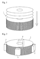
- Fig. 3 is a plane diagram showing a connected portion between the rotor yoke 1 and the copper plated permanent magnet 2.
- the copper plated permanent magnet 2 is structured such that an overall face of a permanent magnet 3 composed of a Nd-Fe-B type rare earth magnet is covered with a copper plated film 4 beforehand as shown in Fig. 3.
- This copper plated permanent magnet 2 is disposed on the peripheral face of the rotor yoke 1, and welding by laser beam is performed thereon.
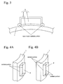
- Fig. 4A is a perspective diagram showing one example of a beam weld feature between the plated permanent magnet 2 and the rotor yoke 1.
- a welded portion by laser beam is a part (wavy line portions in Fig. 4A) of a periphery of contact face between the rotor yoke 1 and the copper plated permanent magnet 2.
- Fig. 4B is a perspective diagram showing another example of a beam weld feature between the rotor yoke 1 and the copper plated permanent magnet 2.
- a welded portion by laser beam is an overall periphery (wavy line portion in Fig. 4B) of a contact face between the rotor yoke 1 and the copper plated permanent magnet 2.
- connection features shown in Figs. 3, 4A and 4B When welding by laser beam is performed in accordance with the connection features shown in Figs. 3, 4A and 4B, the copper plated film 4 as a laser beam irradiated portion is melted, the copper plated film 4 serves as a brazing filler metal in welding, so that connection between the rotor yoke 1 and the permanent magnet 3 is strong in Fig. 3. Therefore, the connection strength at high temperature and at high speed and the durability including thermal shock can be improved.
- a welded portion by laser beam is an overall of a periphery of contact face between the rotor yoke 1 and the copper plated permanent magnet 2 as shown in Fig. 4B, the above connection is stronger and the durability can be improved more.
- Fig. 3 When welding by laser beam is performed in accordance with the connection features shown in Figs. 3, 4A and 4B, the copper plated film 4 serves as a brazing filler metal in welding, so that connection between the rotor yoke 1
- the copper plated film 4 serves as a buffer between the rotor yoke 1 and the permanent magnet 3, elastic deformation of the rotor yoke 1 is prevented under large temperature change, and thermal durability can be improved.
- the copper plated plate 4 between the rotor yoke 1 and the permanent magnet 3 has large thermal conductivity, so that heat dissipation from the permanent magnet 3 to the rotor yoke 1 is high, and the stable use of the rotor is realized.
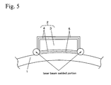
- FIG. 5 is a plane diagram showing the detailed connection feature between the rotor yoke 1 and the plated permanent magnet 2 shown in Fig. 2.
- the same numeral references as in the First Embodiment denote the same structural elements as in the First Embodiment, and explanations of the structural elements and the actions thereof are omitted.
- the plated permanent magnet 2 is structured such that an overall face of the permanent magnet 3 composed of a Nd-Fe-B type rare earth magnet is covered with a copper plated film 4 having a thickness of 30 ⁇ m, and a periphery of the copper plated film 4 is covered with a nickel plated film 5 having a thickness of 30 ⁇ m.
- an outside of the copper plated film is favorably covered with the nickel plated film 5 in order to sufficiently have good durability of nickel.
- the plated permanent magnet 2 formed in the above manner is disposed on a peripheral face of the rotor yoke 1, and then welding by laser beam is performed thereat.
- the films 4 and 5 serve as brazing filler metals in welding, so that connection between the rotor yoke 1 and the permanent magnet 3 in Fig. 5 is strong.
- the copper plated film 4 and the nickel plated film 5 have a thickness of not less than 25 ⁇ m in total, the above strong connection can be sufficiently achieved.
- the rotor since the plated film has two layers of the copper plated film 4 and the nickel plated film 5, the rotor can have good thermal conductivity of copper and good durability of nickel.
- the cost can be reduced.
- the copper plated film 4 and the nickel plated film 5 have a thickness of not more than 90 ⁇ m in total, the metal films are not excessively used, and the cost can be thereby reduced sufficiently.
- results of respective performance evaluations of the rotor for a permanent magnet type motor of the present invention are shown hereinafter.
- the respective performance evaluation tests were performed assuming rotors for permanent magnetic type motors produced in accordance with the connection features shown in Figs. 3 and 4A or the connection features shown in Figs. 4A and 5.
- a permanent magnet was composed of a Nd-Fe-B type rare earth metal, an overall surface of the permanent magnet was plated with at least one of copper and nickel, and a rotor yoke member was composed of an iron type material.
- an object of the present invention is that all characteristics regarding the durability, the cost, the magnetic efficiency based on the air gap between the rotor and the rotor stator, the magnetic efficiency based on the included gap between the permanent magnet and the rotor yoke, the heat dissipation, and the connection strength between the rotor yoke and the permanent magnet reach high levels as described above, evaluation tests for all these characteristics are desirable to perform.
- evaluation tests for all these characteristics are desirable to perform.
- the cost can obviously be reduced.
- connection strength between the rotor yoke and the permanent magnet is shown in the following Examples. The connection strength at high temperature and at high speed rotation and the durability including thermal shock can be anticipated from the above results of the connection strength between the rotor yoke and the permanent magnet.
- a rotor yoke member 11 of an iron type material and a plated permanent magnet 12 of a Nd-Fe-B type rare earth magnet plated with silver having a thickness of 50 ⁇ m on an entire face thereof were prepared, and laser beam welding was performed at a part (wavy line portion in the Figure) of a periphery on a contact face between the rotor yoke 11 and the plated permanent magnet 12 in a state in which these were contacted to each other as shown in Fig. 6A.
- tension shear test based on JIS K 6850 was performed on the rotor yoke 11 and the plated permanent magnet 12 which were connected.
- a rotor yoke member 13 of an iron type material and a permanent magnet 14 of a Nd-Fe-B type rare earth magnet were prepared, and, as shown in Fig. 6B, epoxy adhesive (product of BRENNY GIKEN Co.) was coated on an entire contact face therebetween at a thickness of 80 ⁇ m, so that these were adhered.
- epoxy adhesive product of BRENNY GIKEN Co.
- tension shear test based on JIS K 6850 was performed on the rotor yoke 13 and the plated permanent magnet 14 which were connected.
- Respective test conditions were the same as in Example 1.
- a rotor yoke material 13 of an iron type material and a permanent magnet 14 of a Nd-Fe-B type rare earth magnet were prepared, and, as shown in Fig. 6B, an epoxy adhesive (product of "Bond E Set” of product of KONISHI Co., LTD.) was coated on an entire contact face therebetween at a thickness of 80 ⁇ m, so that these were adhered.
- tension shear test based on JIS K 6850 was performed on the rotor yoke 13 and the plated permanent magnet 14 which were connected.
- Respective test conditions were the same as in Example 1.
- the above evaluation test results regarding Example 1 and Comparative Examples 1 and 2 are shown in Fig. 7.
- thermal conductivity at the connection portion in the Figure was measured by laser flash method based on JIS R 1611.
- a rotor yoke material 13 of an iron type material and a permanent magnet 14 of a Nd-Fe-B type rare earth magnet were prepared, and, as shown in Fig. 6B, an epoxy adhesive (product of BRENNY GIKEN Co.) was coated on an entire contact face so as to adhere them.
- thermal conductivity at a connection portion in the connection portion was measured by laser flash method based on JIS R 1611.
- thermal conductivity exhibited high values of 50 to 400 w/m • K. This is because there is a contact portion of the metals by including the copper plated film between the permanent magnet and the rotor yoke. Therefore, in Example 2, good heat dissipation is realized.
- thermal conductivity exhibited very low values of 0.1 to 0.9 w/m • K. This is because heat accumulates in the resin portion by including the epoxy resin between the permanent magnet and the rotor yoke so that good thermal conductivity is not realized. Therefore, in Comparative Example 3, good heat dissipation is not realized.
- Each rotor was produced by connecting each plated permanent magnet of a rare earth magnet having copper plating (each thickness of 30 ⁇ m (Example 3), 40 ⁇ m (Example 4), 50 ⁇ m (Example 5), 60 ⁇ m (Example 6), and 80 ⁇ m (Example 7)) to a rotor yoke (outside diameter of 170 mm, thickness of 55 mm) of an iron type material by laser beam welding.
- tension shear test based on JIS K 6850 was performed on the rotor yoke and the permanent magnet which were connected to each other.
- Respective test conditions were the same as in Example 1.
- Tension shear test performance temperature was 200°C. Removal of the permanent magnet from the rotor yoke was examined by rotating each rotor at 8000rpm for 30 minutes.
- Each rotor was produced by connecting each plated permanent magnet of a rare earth magnet having copper plating (each thickness of 20 ⁇ m (Comparative Example 4) and 100 ⁇ m (Comparative Example 5)) to a rotor yoke (outside diameter of 170 mm, thickness of 55 mm) of an iron type material by laser beam welding.
- tension shear test based on JIS K 6850 was performed on the rotor yoke and the permanent magnet which were connected to each other.
- Respective test conditions were the same as in Example 1.
- Tension shear test performance temperature was 200°C. Removal of the permanent magnet from the rotor yoke was examined by rotating each rotor at 8000rpm for 30 minutes.
- Fig. 8 is a graph showing results of tension shear tests regarding Examples 3 to 7 and Comparative Examples 4 and 5. According to the Figure, in Examples 3 to 7, as the thickness of copper plating increases, connection strength increases, so that these Examples are favorable from the point of view of production cost. Since loss of the permanent magnet from the rotor yoke did not occur when the rotor was rotated in the above manner in Examples 3 to 7, it was confirmed that sufficient connection strength for use was obtained.
- Comparative Example 4 since removal of the permanent magnet from the rotor yoke occurred when the rotor was rotated in the above manner, sufficient connection strength for use was not obtained, so that the Comparative Example 4 is not desirable example.
- Comparative Example 5 as shown in Fig. 8, however the thickness of copper plating is increased more than in Example 7, and connection strength did not increase, so that it was not favorable from the point of view of production cost.
- favorable range of metal film thickness is 25 to 90 ⁇ m as described in claim 3 of the application.
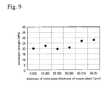
- Each rotor was produced by connecting a plated permanent magnet, which was structured such that a permanent magnet of rare earth magnet of Nd-Fe-B type was plated with copper (each thickness of 50 ⁇ m (Example 8), 40 ⁇ m (Example 9), 30 ⁇ m (Example 10), 20 ⁇ m (Example 11), 10 ⁇ m (Example 12), and 0 ⁇ m (Example 13)) and was plated with nickel (each thickness of 0 ⁇ m (Example 8), 10 ⁇ m (Example 9), 20 ⁇ m (Example 10), 30 ⁇ m (Example 11), 40 ⁇ m (Example 12), and 50 ⁇ m (Example 13)) thereon, to a rotor yoke (outside diameter of 170 mm, thickness of 55 mm) of an iron type material, by laser beam welding.
- tension shear test based on JIS K 6850 was performed on the rotor yoke
- connection strength desirable for use is obtained in view of Fig. 8. It is confirmed that connection strength is almost unaffected when thickness of copper plating and nickel plating varies with entire metal film thickness fixed.
Abstract
Description
Claims (6)
- A rotor for a permanent magnet type motor, comprising:wherein the rotor yoke and the permanent magnet are subjected to beam welding.a rotor yoke;a permanent magnet connected on a surface of the rotor yoke; anda metal film which is disposed between the rotor yoke and the permanent magnet,
- The rotor for a permanent magnet type motor according to claim 1,
wherein the metal film is formed on a surface of the permanent magnet. - The rotor for a permanent magnet type motor according to claim 1 or 2,
wherein the metal film has a thickness of 25 to 90 µm. - The rotor for a permanent magnet type motor according to one of claims 1 to 3,
wherein the metal film contains at least of one of nickel and copper. - The rotor for a permanent magnet type motor according to claim 4,
wherein the metal film has a copper film composed of copper and a nickel film composed of nickel. - The rotor for a permanent magnet type motor according to one of claims 1 to 5,
wherein the rotor yoke has a stacked structure.
Applications Claiming Priority (5)
| Application Number | Priority Date | Filing Date | Title |
|---|---|---|---|
| JP2003018854 | 2003-01-28 | ||
| JP2003018854 | 2003-01-28 | ||
| JP2003023179 | 2003-01-31 | ||
| JP2003023179 | 2003-01-31 | ||
| PCT/JP2004/000452 WO2004068673A1 (en) | 2003-01-28 | 2004-01-21 | Rotor for permanent magnet motor |
Publications (3)
| Publication Number | Publication Date |
|---|---|
| EP1589635A2 true EP1589635A2 (en) | 2005-10-26 |
| EP1589635A4 EP1589635A4 (en) | 2007-02-07 |
| EP1589635B1 EP1589635B1 (en) | 2012-05-09 |
Family
ID=32828891
Family Applications (1)
| Application Number | Title | Priority Date | Filing Date |
|---|---|---|---|
| EP04703914A Expired - Fee Related EP1589635B1 (en) | 2003-01-28 | 2004-01-21 | Rotor for permanent magnet motor |
Country Status (3)
| Country | Link |
|---|---|
| US (1) | US7378772B2 (en) |
| EP (1) | EP1589635B1 (en) |
| JP (1) | JPWO2004068673A1 (en) |
Cited By (2)
| Publication number | Priority date | Publication date | Assignee | Title |
|---|---|---|---|---|
| WO2011100987A1 (en) * | 2010-02-16 | 2011-08-25 | Siemens Aktiengesellschaft | Method for assembling part of a generator, generator and wind turbine |
| WO2016155734A1 (en) * | 2015-04-02 | 2016-10-06 | Bühler Motor GmbH | Magnet sensor |
Families Citing this family (7)
| Publication number | Priority date | Publication date | Assignee | Title |
|---|---|---|---|---|
| US7723894B2 (en) * | 2004-12-20 | 2010-05-25 | General Electric Company | Electrical machine with improved loss characteristics and method of making same |
| CN101278173B (en) * | 2005-10-06 | 2011-12-21 | 微动公司 | Magnet apparatus |
| DE102010041585A1 (en) * | 2010-09-29 | 2012-03-29 | Siemens Aktiengesellschaft | Rotor for use as inner rotor of e.g. linear electric machine for permanent synchronous generator of wind power station, has permanent magnets mounted on periphery of rotor body where each pocket is intractable and connected with rotor body |
| DE102010041593A1 (en) * | 2010-09-29 | 2012-03-29 | Siemens Aktiengesellschaft | Cover for protecting permanent magnets of pole of rotor utilized as e.g. outer rotor in wind force generator of gearless wind turbine, has central cover region arranged between two side walls |
| US9263926B2 (en) * | 2012-09-10 | 2016-02-16 | Remy Technologies, L.L.C. | Permanent magnet electric machine having magnets provided with a thermal enhancement bonding coating |
| CN108781029B (en) * | 2016-03-28 | 2020-11-03 | 爱信艾达株式会社 | Method for manufacturing rotor |
| CN113228207B (en) | 2018-12-25 | 2023-08-01 | 大赛璐美华株式会社 | Rare earth magnet precursor or rare earth magnet molded body having roughened structure on surface, and method for producing same |
Citations (6)
| Publication number | Priority date | Publication date | Assignee | Title |
|---|---|---|---|---|
| JPS5586361A (en) * | 1978-12-20 | 1980-06-30 | Citizen Watch Co Ltd | Manufacture of rotor for clock motor |
| FR2556519A1 (en) * | 1983-12-08 | 1985-06-14 | Labinal | Enhancement to machines with magnets and in particular to machines with magnets with the rotor and method of manufacturing parts of these machines |
| JPH04101640A (en) * | 1990-08-17 | 1992-04-03 | Mitsubishi Electric Corp | Rotor of permanent magnet rotating machine |
| GB2262288A (en) * | 1991-11-27 | 1993-06-16 | Hitachi Metals Ltd | Copper electroplated permanent magnet of rare-earth element/transition metal system |
| JPH0657055U (en) * | 1992-12-25 | 1994-08-05 | 株式会社安川電機 | Permanent magnet rotor |
| US6006418A (en) * | 1995-02-07 | 1999-12-28 | Denyo Kabushiki Kaisha | Method of manufacturing a rotors with permanent magnet |
Family Cites Families (15)
| Publication number | Priority date | Publication date | Assignee | Title |
|---|---|---|---|---|
| JPS558361A (en) * | 1978-07-03 | 1980-01-21 | Daiwa Seisakusho:Kk | Casting mold molding method |
| JPS6146151A (en) * | 1984-08-09 | 1986-03-06 | Toshiba Corp | Manufacture of rotor with permanent magnet |
| JPH0366535U (en) * | 1989-10-26 | 1991-06-27 | ||
| JPH0638415A (en) | 1992-07-22 | 1994-02-10 | Hitachi Metals Ltd | Permanent magnet type rotor |
| JPH07177712A (en) | 1993-12-17 | 1995-07-14 | Hitachi Metals Ltd | Magnet member and manufacture thereof |
| JPH0880015A (en) | 1994-09-01 | 1996-03-22 | Meidensha Corp | Electric rotary machine |
| JPH08223835A (en) | 1995-02-09 | 1996-08-30 | Honda Motor Co Ltd | Permanent magnet rotor |
| JPH09320826A (en) * | 1996-05-27 | 1997-12-12 | Sumitomo Special Metals Co Ltd | Highly anticorrosive rare earth magnet |
| JP3347939B2 (en) * | 1996-06-06 | 2002-11-20 | 三菱電機株式会社 | Permanent magnet rotor |
| SE511896C2 (en) * | 1996-12-04 | 1999-12-13 | Vilmos Toeroek | Electric rotary motor with pronounced poles |
| JP2000083334A (en) * | 1998-09-04 | 2000-03-21 | Toshiba Corp | Permanent magnet type rotor, its manufacture and magnet fixing apparatus thereof |
| JP3589134B2 (en) * | 2000-01-12 | 2004-11-17 | 株式会社デンソー | Stator manufacturing method and apparatus |
| JP4689058B2 (en) * | 2001-02-16 | 2011-05-25 | キヤノン株式会社 | Linear motor, stage apparatus, exposure apparatus, and device manufacturing method |
| JP2002272033A (en) | 2001-03-13 | 2002-09-20 | Nissan Motor Co Ltd | Rotor of permanent magnet synchronous motor and manufacturing method |
| JP3684344B2 (en) * | 2001-11-02 | 2005-08-17 | 三菱電機株式会社 | Permanent magnet rotor and manufacturing method thereof |
-
2004
- 2004-01-21 JP JP2005504679A patent/JPWO2004068673A1/en active Pending
- 2004-01-21 EP EP04703914A patent/EP1589635B1/en not_active Expired - Fee Related
- 2004-01-21 US US10/541,327 patent/US7378772B2/en not_active Expired - Fee Related
Patent Citations (6)
| Publication number | Priority date | Publication date | Assignee | Title |
|---|---|---|---|---|
| JPS5586361A (en) * | 1978-12-20 | 1980-06-30 | Citizen Watch Co Ltd | Manufacture of rotor for clock motor |
| FR2556519A1 (en) * | 1983-12-08 | 1985-06-14 | Labinal | Enhancement to machines with magnets and in particular to machines with magnets with the rotor and method of manufacturing parts of these machines |
| JPH04101640A (en) * | 1990-08-17 | 1992-04-03 | Mitsubishi Electric Corp | Rotor of permanent magnet rotating machine |
| GB2262288A (en) * | 1991-11-27 | 1993-06-16 | Hitachi Metals Ltd | Copper electroplated permanent magnet of rare-earth element/transition metal system |
| JPH0657055U (en) * | 1992-12-25 | 1994-08-05 | 株式会社安川電機 | Permanent magnet rotor |
| US6006418A (en) * | 1995-02-07 | 1999-12-28 | Denyo Kabushiki Kaisha | Method of manufacturing a rotors with permanent magnet |
Non-Patent Citations (1)
| Title |
|---|
| See also references of WO2004068673A2 * |
Cited By (4)
| Publication number | Priority date | Publication date | Assignee | Title |
|---|---|---|---|---|
| WO2011100987A1 (en) * | 2010-02-16 | 2011-08-25 | Siemens Aktiengesellschaft | Method for assembling part of a generator, generator and wind turbine |
| CN102754310A (en) * | 2010-02-16 | 2012-10-24 | 西门子公司 | Method for assembling part of a generator, generator and wind turbine |
| CN102754310B (en) * | 2010-02-16 | 2015-09-16 | 西门子公司 | For assembling the method for generator part, generator and wind turbine |
| WO2016155734A1 (en) * | 2015-04-02 | 2016-10-06 | Bühler Motor GmbH | Magnet sensor |
Also Published As
| Publication number | Publication date |
|---|---|
| JPWO2004068673A1 (en) | 2006-05-25 |
| US7378772B2 (en) | 2008-05-27 |
| EP1589635B1 (en) | 2012-05-09 |
| EP1589635A4 (en) | 2007-02-07 |
| US20060043810A1 (en) | 2006-03-02 |
| WO2004068673A2 (en) | 2004-08-12 |
| WO2004068673A3 (en) | 2004-10-28 |
Similar Documents
| Publication | Publication Date | Title |
|---|---|---|
| EP1589635B1 (en) | Rotor for permanent magnet motor | |
| EP1982403B1 (en) | Rotor for electric motor | |
| EP0786854B1 (en) | Rotor for rotating machine, method of manufacturing same, and magnet unit | |
| KR100642034B1 (en) | Low temperature sputter target bonding method and target assemblies produced thereby | |
| JPH08331784A (en) | Permanent-magnet type rotary electric machine | |
| JP2004187411A (en) | Bonded structural body | |
| CN108475980B (en) | Magnetic gear transmission device | |
| JP4930127B2 (en) | Surface magnet type rotor and manufacturing method thereof | |
| JPH0851693A (en) | Magnetic circuit unit for microspeaker and its manufacture | |
| JPH0638415A (en) | Permanent magnet type rotor | |
| JPWO2003052161A1 (en) | Method for joining magnetic target and backing plate and magnetic target | |
| JP4333277B2 (en) | Low noise reactor and method for manufacturing the same | |
| JP2007068270A (en) | Component for motor | |
| JP2005287134A (en) | Method of manufacturing motor core, motor core and high frequency motor | |
| KR100651296B1 (en) | Coupling structure and method of the permanent magnet of a motor | |
| JP2013126311A (en) | Rotary electric machine | |
| JP2001231191A (en) | Stator core and small-sized motor mounting it | |
| JPH09117082A (en) | Laminated rotor and manufacture thereof | |
| JP3631808B2 (en) | Rotor for rotating machine, method for manufacturing the rotor, and magnet unit | |
| CN1745506A (en) | Rotor for permanent magnet motor | |
| JP2003264963A (en) | Rotor and manufacturing method therefor | |
| EP4354708A1 (en) | Motor rotor | |
| JP3373950B2 (en) | Heat bonding method of two kinds of members having different thermal expansion coefficients | |
| JP2003153477A (en) | Rare earth element magnet unit | |
| JP4646369B2 (en) | Copper bus bar with excellent corrosion resistance and method for producing the same |
Legal Events
| Date | Code | Title | Description |
|---|---|---|---|
| PUAI | Public reference made under article 153(3) epc to a published international application that has entered the european phase |
Free format text: ORIGINAL CODE: 0009012 |
|
| 17P | Request for examination filed |
Effective date: 20050622 |
|
| AK | Designated contracting states |
Kind code of ref document: A2 Designated state(s): AT BE BG CH CY CZ DE DK EE ES FI FR GB GR HU IE IT LI LU MC NL PT RO SE SI SK TR |
|
| AX | Request for extension of the european patent |
Extension state: AL LT LV MK |
|
| DAX | Request for extension of the european patent (deleted) | ||
| RBV | Designated contracting states (corrected) |
Designated state(s): DE FR |
|
| A4 | Supplementary search report drawn up and despatched |
Effective date: 20070109 |
|
| 17Q | First examination report despatched |
Effective date: 20071011 |
|
| GRAP | Despatch of communication of intention to grant a patent |
Free format text: ORIGINAL CODE: EPIDOSNIGR1 |
|
| GRAS | Grant fee paid |
Free format text: ORIGINAL CODE: EPIDOSNIGR3 |
|
| GRAA | (expected) grant |
Free format text: ORIGINAL CODE: 0009210 |
|
| RBV | Designated contracting states (corrected) |
Designated state(s): DE GB |
|
| RIN1 | Information on inventor provided before grant (corrected) |
Inventor name: MUROGA, SHIGEKI,C/O KABUSHIKI KAISHA HONDA GIJUTSU Inventor name: HIGASHI, TAKAYUKI,KABUSHIKI KAISHA HONDA GIJUTSU K Inventor name: KITA, TERUYOSHI,C/O KABUSHIKI KAISHA HONDA GIJUTSU Inventor name: SHIMIZU, HARUHIKO,KABUSHIKI KAISHA HONDA GIJUTSU K |
|
| AK | Designated contracting states |
Kind code of ref document: B1 Designated state(s): DE GB |
|
| RAP1 | Party data changed (applicant data changed or rights of an application transferred) |
Owner name: HONDA MOTOR CO., LTD. |
|
| REG | Reference to a national code |
Ref country code: GB Ref legal event code: FG4D |
|
| RIN1 | Information on inventor provided before grant (corrected) |
Inventor name: MUROGA, SHIGEKI Inventor name: HIGASHI, TAKAYUKI Inventor name: KITA, TERUYOSHI Inventor name: SHIMIZU, HARUHIKO |
|
| REG | Reference to a national code |
Ref country code: DE Ref legal event code: R096 Ref document number: 602004037736 Country of ref document: DE Effective date: 20120705 |
|
| PLBE | No opposition filed within time limit |
Free format text: ORIGINAL CODE: 0009261 |
|
| STAA | Information on the status of an ep patent application or granted ep patent |
Free format text: STATUS: NO OPPOSITION FILED WITHIN TIME LIMIT |
|
| 26N | No opposition filed |
Effective date: 20130212 |
|
| PGFP | Annual fee paid to national office [announced via postgrant information from national office to epo] |
Ref country code: DE Payment date: 20121130 Year of fee payment: 10 |
|
| REG | Reference to a national code |
Ref country code: DE Ref legal event code: R097 Ref document number: 602004037736 Country of ref document: DE Effective date: 20130212 |
|
| GBPC | Gb: european patent ceased through non-payment of renewal fee |
Effective date: 20130121 |
|
| PG25 | Lapsed in a contracting state [announced via postgrant information from national office to epo] |
Ref country code: GB Free format text: LAPSE BECAUSE OF NON-PAYMENT OF DUE FEES Effective date: 20130121 |
|
| REG | Reference to a national code |
Ref country code: DE Ref legal event code: R119 Ref document number: 602004037736 Country of ref document: DE |
|
| REG | Reference to a national code |
Ref country code: DE Ref legal event code: R119 Ref document number: 602004037736 Country of ref document: DE Effective date: 20140801 |
|
| PG25 | Lapsed in a contracting state [announced via postgrant information from national office to epo] |
Ref country code: DE Free format text: LAPSE BECAUSE OF NON-PAYMENT OF DUE FEES Effective date: 20140801 |