JP2005287134A - Method of manufacturing motor core, motor core and high frequency motor - Google Patents
Method of manufacturing motor core, motor core and high frequency motor Download PDFInfo
- Publication number
- JP2005287134A JP2005287134A JP2004095136A JP2004095136A JP2005287134A JP 2005287134 A JP2005287134 A JP 2005287134A JP 2004095136 A JP2004095136 A JP 2004095136A JP 2004095136 A JP2004095136 A JP 2004095136A JP 2005287134 A JP2005287134 A JP 2005287134A
- Authority
- JP
- Japan
- Prior art keywords
- laminated steel
- motor core
- steel plates
- motor
- core
- Prior art date
- Legal status (The legal status is an assumption and is not a legal conclusion. Google has not performed a legal analysis and makes no representation as to the accuracy of the status listed.)
- Pending
Links
Images


Abstract
Description
本発明は鉄板を積層して構成されるモータコアの製造方法及びモータコア及び該モータコアを用いた高周波モータに関するものである。 The present invention relates to a motor core manufacturing method configured by stacking iron plates, a motor core, and a high-frequency motor using the motor core.
モータコアの鉄損、例えばヒステリシス或は渦電流の発生による損失は、該モータコア用のコイルに印加する電流の周波数の2乗に比例して増大することが知られており、又鉄損特に渦電流の発生による損失は、モータコアを構成する鉄板(電磁鋼板)の板厚の2乗に比例して減少することも知られている。 It is known that iron loss of a motor core, for example, loss due to generation of hysteresis or eddy current increases in proportion to the square of the frequency of current applied to the coil for the motor core, and iron loss, particularly eddy current. It is also known that the loss due to the occurrence of the loss decreases in proportion to the square of the plate thickness of the iron plate (magnetic steel plate) constituting the motor core.
この為、従来より高周波モータではモータコアを薄板の電磁鋼板を絶縁して積層して構成し、鉄損を減少させることが行われている。 For this reason, conventionally, in a high-frequency motor, a motor core is configured by insulating and laminating thin electromagnetic steel sheets to reduce iron loss.
モータの高速化に伴うモータの高周波化によって、電磁鋼板(以下積層鋼板と称す)の板厚の一層の薄肉化が進み、現在積層鋼板の板厚は0.35mm以下、例えば0.1mmにもなっている。 As the motor speed increases, the thickness of the electromagnetic steel sheet (hereinafter referred to as the laminated steel sheet) is further reduced due to the higher frequency of the motor, and the thickness of the laminated steel sheet is currently 0.35 mm or less, for example, 0.1 mm. It has become.
この為モータコアを製造する場合、製造の過程で或は製品として、多数積層された薄板の積層鋼板を一体化する必要があり、従来より積層鋼板を一体化する為の種々の手段が採られている。 For this reason, when manufacturing a motor core, it is necessary to integrate a number of thin laminated steel plates in the manufacturing process or as a product, and various means for integrating laminated steel plates have been adopted conventionally. Yes.
例えば、特許文献1ではカシメにより積層鋼板を一体化しており、又特許文献2では積層鋼板間を熱融着性のガラス系無機物により接着している。又、その他溶接により積層鋼板を一体化する方法もある。
For example, in Patent Document 1, laminated steel plates are integrated by caulking, and in
図3によりカシメを用いたモータコアの製造方法について説明する。 A method for manufacturing a motor core using caulking will be described with reference to FIG.
薄板の原板から積層鋼板の打抜きに合わせて帯状のスリットに切断し、該スリットから積層鋼板を金型等で打抜き加工する。 A thin strip is cut into a strip-shaped slit in accordance with the punching of the laminated steel sheet, and the laminated steel sheet is punched with a die or the like from the slit.
積層鋼板を重ね、カシメ型により所要箇所を押出し成形する等変形させ、積層鋼板間を噛合わせ一体化する(以下一体化したものをコアと称す)。 Laminated steel sheets are stacked, a required portion is extruded and deformed by a caulking die, etc., and the laminated steel sheets are meshed and integrated (hereinafter, the integrated structure is referred to as a core).
積層鋼板の打抜き加工、カシメ加工により加工歪みが発生する。加工歪みは、積層鋼板の磁気特性を劣化させるので、焼鈍が行われる。焼鈍は700℃以上の温度で実施され、積層鋼板の歪みを除去し、磁気特性を回復させる。 Processing distortion occurs due to punching and caulking of laminated steel sheets. Since the processing strain degrades the magnetic properties of the laminated steel sheet, annealing is performed. Annealing is carried out at a temperature of 700 ° C. or higher to remove the distortion of the laminated steel sheet and restore the magnetic properties.
焼鈍が完了することで、製品としてのコアが完成する。 By completing the annealing, the core as a product is completed.
カシメを用いたモータコアの製造方法では、カシメの為孔明け、押出し等積層鋼板を変形させる。この為カシメ部分では磁気が乱れ損失が発生するので、カシメ部分を磁気が流れない様にしなければならず、コア形状の制約、カシメ箇所の制限等設計上の制約或は発生させる磁気特性に制約が起きるという問題があった。 In the manufacturing method of a motor core using caulking, laminated steel sheets such as drilling and extrusion are deformed for caulking. For this reason, since the magnetism is disturbed and loss occurs in the caulking portion, it is necessary to prevent the magnetism from flowing through the caulking portion, and there are constraints on the design such as the core shape and the caulking location, or the magnetic characteristics to be generated. There was a problem that happened.
図4により、積層鋼板間を熱融着性のガラス系無機物により接着するモータコアの製造方法について説明する。 With reference to FIG. 4, a method for manufacturing a motor core in which laminated steel sheets are bonded with a heat-fusible glass-based inorganic material will be described.
鋼板材料に熱融着性のガラス系無機物を塗布(コーティング)する。コーティングは薄板の原板の状態で全面に塗布するか、又は、薄板の原板から積層鋼板の打抜きに合わせて帯状のスリットに切断し、該スリットの全面に塗布する。 A heat-fusible glass-based inorganic material is applied (coated) to the steel plate material. The coating is applied to the entire surface in the state of a thin original plate, or is cut into a band-shaped slit from the thin original plate in accordance with the punching of the laminated steel plate, and applied to the entire surface of the slit.
前記スリットから積層鋼板を金型等で打抜き加工する。打抜いた積層鋼板を重ねる。 A laminated steel sheet is punched from the slit with a die or the like. Stack the punched laminated steel sheets.
打抜き加工時の加工歪みを除去する為の焼鈍を行う。焼鈍時の加熱により、ガラス系無機物が溶融して積層鋼板間を接着する。 Annealing is performed to remove machining distortion during punching. By heating at the time of annealing, the glass-based inorganic material is melted and bonded between the laminated steel plates.
焼鈍が完了することで、磁気特性が回復すると共に積層鋼板が接着により一体化し、コアが形成される。 When the annealing is completed, the magnetic properties are restored, and the laminated steel plates are integrated by bonding, thereby forming a core.
ガラス系無機物により積層鋼板を接着するモータコアの製造方法では、ガラス系無機物をスリットに塗布する為の、大掛りな設備が必要となり、更に一般的にガラス系無機物には接着力がなく、特殊なガラス系無機物が必要となり、材料費が高くなる等、モータコアを安価に製作することができないという問題があった。 In the manufacturing method of the motor core in which the laminated steel sheet is bonded with the glass-based inorganic material, a large-scale facility for applying the glass-based inorganic material to the slit is required, and the glass-based inorganic material generally has no adhesive force and is special. There was a problem that the motor core could not be manufactured at a low cost, such as the need for glass-based inorganic materials and high material costs.
又、図5により、溶接により積層鋼板を一体化するモータコアの製造方法について説明する。 Moreover, the manufacturing method of the motor core which integrates a laminated steel plate by welding is demonstrated with FIG.
尚、積層鋼板の積層工程迄は上記したカシメを用いたモータコアの製造方法と同様である。 Note that the process up to the lamination process of the laminated steel sheets is the same as the motor core manufacturing method using the caulking described above.
積層鋼板をコア状に積上げると、所要箇所を板厚方向に溶接して積層鋼板を一体化する。一体化後、コアの焼鈍を行う。尚、溶接部の組織の劣化等が問題となる場合は、焼鈍後に溶接を行う。 When the laminated steel plates are stacked in a core shape, the required portions are welded in the plate thickness direction to integrate the laminated steel plates. After integration, the core is annealed. In addition, when deterioration of the structure of a welded part or the like becomes a problem, welding is performed after annealing.
溶接により積層鋼板を一体化するモータコアの製造方法では、溶接部分で積層鋼板間が短絡することとなり、磁気が通過する部分は溶接を避けなければならず、溶接箇所に制約がある。又、ステータ側のコアとして複数部分に分割したものがあるが、斯かる分割型のコアでは、溶接箇所が多くなり、又磁気を通過する部分を避けて溶接することが困難になるので、実質的に溶接を用いることができないという問題があった。ロータ側のコアは磁界の中を回転するものであり、磁気を通過する部分を避けて溶接することが困難であり、溶接でモータコアを製造することができないという問題があった。 In the manufacturing method of the motor core in which the laminated steel plates are integrated by welding, the laminated steel plates are short-circuited at the welded portions, and the portions where magnetism passes must be avoided, and there are restrictions on the welding locations. In addition, there is a stator-side core that is divided into a plurality of parts. However, with such a split-type core, the number of welds increases, and it becomes difficult to avoid the part that passes through the magnetism. In other words, there was a problem that welding could not be used. The rotor-side core rotates in a magnetic field, and it is difficult to perform welding while avoiding a portion that passes through the magnetism, and there is a problem that a motor core cannot be manufactured by welding.
本発明は斯かる実情に鑑み、特殊な材料を用いることなく、大規模な装置を設備することなく、積層鋼板による分割コア、ロータコアを安価に製造するモータコアの製造方法及びモータコアを提供し、更に該モータコアを用いた高周波モータを提供するものである。 In view of such circumstances, the present invention provides a motor core manufacturing method and a motor core for manufacturing a split core and a rotor core at low cost without using a special material, without installing a large-scale apparatus, and further, A high frequency motor using the motor core is provided.
本発明は、積層鋼板が積層され、該積層鋼板が一体化されモータコアが製造されるモータコアの製造方法に於いて、焼鈍工程と、焼鈍工程後に積層された前記積層鋼板を接着する工程とを具備するモータコアの製造方法に係るものである。 The present invention provides a motor core manufacturing method in which laminated steel plates are laminated and the laminated steel plates are integrated to produce a motor core, and includes an annealing step and a step of bonding the laminated steel plates laminated after the annealing step. The present invention relates to a method for manufacturing a motor core.
又本発明は、前記積層鋼板の接着は該積層鋼板間に接着剤を真空含浸させて行うモータコアの製造方法に係るものである。 The present invention also relates to a method for manufacturing a motor core, wherein the laminated steel plates are bonded by vacuum impregnating an adhesive between the laminated steel plates.
又本発明は、所要枚数の積層鋼板が、真空含浸により該積層鋼板間に浸透された接着剤により接着され一体化されて構成されたモータコアに係るものである。 In addition, the present invention relates to a motor core configured such that a required number of laminated steel plates are bonded and integrated by an adhesive permeated between the laminated steel plates by vacuum impregnation.
又本発明は、前記モータコアが所要に分割され、分割部分が所要枚数の前記積層鋼板により構成され、真空含浸により該積層鋼板間に浸透された接着剤により前記積層鋼板が接着され一体化されたモータコアに係るものである。 In the present invention, the motor core is divided as necessary, the divided portion is constituted by the required number of the laminated steel plates, and the laminated steel plates are bonded and integrated by an adhesive that has penetrated between the laminated steel plates by vacuum impregnation. It concerns the motor core.
更に又本発明は、モータコアが所要枚数の積層鋼板の積層により構成され、真空含浸により該積層鋼板間に浸透された接着剤により前記積層鋼板が接着され一体化された高周波モータに係るものである。 Furthermore, the present invention relates to a high frequency motor in which a motor core is formed by laminating a required number of laminated steel plates, and the laminated steel plates are bonded and integrated by an adhesive that has permeated between the laminated steel plates by vacuum impregnation. .
本発明によれば、積層鋼板が積層され、該積層鋼板が一体化されモータコアが製造されるモータコアの製造方法に於いて、焼鈍工程と、焼鈍工程後に積層された前記積層鋼板を接着する工程とを具備するので、接着に特殊な接着剤を使用する必要がなく、又接着に大掛りな装置を必要とすることがなく、更にモータコアの磁気特性を損うことがない。 According to the present invention, in a motor core manufacturing method in which laminated steel plates are laminated and the laminated steel plates are integrated to produce a motor core, an annealing step, and a step of bonding the laminated steel plates laminated after the annealing step; Therefore, it is not necessary to use a special adhesive for bonding, no large apparatus is required for bonding, and the magnetic properties of the motor core are not impaired.
又本発明によれば、所要枚数の積層鋼板が、真空含浸により該積層鋼板間に浸透された接着剤により接着され一体化されて構成されたので、接着に特殊な接着剤を使用する必要がなく、又接着に大掛りな装置を必要とすることがなく、更にモータコアの磁気特性を損うことがない。 Also, according to the present invention, the required number of laminated steel plates are bonded and integrated with an adhesive permeated between the laminated steel plates by vacuum impregnation, and therefore, it is necessary to use a special adhesive for bonding. In addition, there is no need for a large apparatus for bonding, and the magnetic properties of the motor core are not impaired.
又本発明によれば、前記モータコアが所要に分割され、分割部分が所要枚数の前記積層鋼板により構成され、真空含浸により該積層鋼板間に浸透された接着剤により前記積層鋼板が接着され一体化されたので、分割型のモータコアに対しても、モータコアの磁気特性を損うことがない。 Further, according to the present invention, the motor core is divided as required, the divided portion is constituted by the required number of the laminated steel plates, and the laminated steel plates are bonded and integrated by an adhesive that has penetrated between the laminated steel plates by vacuum impregnation. Therefore, the magnetic characteristics of the motor core are not impaired even with respect to the split motor core.
又本発明によれば、モータコアが所要枚数の積層鋼板の積層により構成され、真空含浸により該積層鋼板間に浸透された接着剤により前記積層鋼板が接着され一体化されたので、安価で磁気特性に優れた高周波モータとすることができる等の優れた効果を発揮する。 Further, according to the present invention, the motor core is constituted by laminating a required number of laminated steel sheets, and the laminated steel sheets are bonded and integrated by an adhesive that has permeated between the laminated steel sheets by vacuum impregnation, so that the magnetic properties are low. Excellent effects such as being able to make a high frequency motor excellent in
以下、図面を参照しつつ本発明を実施する為の最良の形態を説明する。 The best mode for carrying out the present invention will be described below with reference to the drawings.
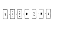
図1を参照しつつ本発明に係るモータコアの製造方法について説明する。 A method for manufacturing a motor core according to the present invention will be described with reference to FIG.
薄板の原板に絶縁膜を形成する。尚、絶縁膜は、薄板製造時に形成され、薄板は絶縁膜が形成されたものが供給されるので、モータコア製作時には絶縁膜の形成工程は省略できる。 An insulating film is formed on the thin original plate. The insulating film is formed at the time of manufacturing the thin plate, and the thin plate is supplied with the insulating film formed thereon. Therefore, the process of forming the insulating film can be omitted when the motor core is manufactured.
原板から積層鋼板の打抜きに合わせて帯状のスリットに切断し(STEP:01)、該スリットから積層鋼板を金型等で打抜き加工する(STEP:02)。 A strip-shaped slit is cut from the original plate in accordance with the punching of the laminated steel plate (STEP: 01), and the laminated steel plate is punched from the slit with a mold or the like (STEP: 02).
前記積層鋼板をコア状に積上げ(STEP:03)、簡単な治具により仮固定する(STEP:04)。 The laminated steel sheets are stacked in a core shape (STEP: 03) and temporarily fixed with a simple jig (STEP: 04).
尚、治具としては積上げられた積層鋼板をクランプするもの、或は積層鋼板が打抜かれると同時にケースに収納され、該ケースによって一体化される様にしたもの等である。積層鋼板を仮固定することで、以下の工程を進行させる場合の取扱い性が向上する。 The jig includes a clamp for stacked laminated steel sheets, or a jig that is stored in a case at the same time as the laminated steel sheets are punched and integrated by the case. By temporarily fixing the laminated steel plate, the handleability in the case of proceeding the following steps is improved.
仮固定された状態で、積層鋼板を700℃以上で焼鈍し(STEP:05)、加工歪みを除去し、磁気特性を回復させる。上記した絶縁膜は、焼鈍により劣化せず、絶縁特性を維持している。 In the temporarily fixed state, the laminated steel sheet is annealed at 700 ° C. or higher (STEP: 05), the processing distortion is removed, and the magnetic properties are recovered. The above-described insulating film is not deteriorated by annealing and maintains the insulating characteristics.
仮固定した状態で、積層鋼板間に真空含浸により、接着剤を染込ませ、積層鋼板間を接着する(STEP:06)。 In the temporarily fixed state, an adhesive is soaked between the laminated steel plates by vacuum impregnation to bond the laminated steel plates (STEP 06).
接着剤としては、エポキシ系樹脂、ポリイミド系樹脂、シリコン系樹脂等の有機樹脂を用いることができる。 As the adhesive, an organic resin such as an epoxy resin, a polyimide resin, or a silicon resin can be used.
又、高周波モータに用いられた場合に要求される耐熱性としては200℃以上を求められることがあるが、上記した有機樹脂の接着剤の中には、耐熱用として、250℃以上でも保つものがあり、有機樹脂の接着剤の使用が可能である。 In addition, the heat resistance required for use in high-frequency motors may be required to be 200 ° C or higher, but some of the above-mentioned organic resin adhesives maintain heat resistance at 250 ° C or higher. It is possible to use an organic resin adhesive.
又、真空含浸は積層鋼板間を真空として積層鋼板間に接着剤を浸透させる方法であり、例えば一体化された積層鋼板を処理槽で真空引し、その後に液状の樹脂を処理槽に移して、真空状態の積層鋼板を接着剤液に浸し、積層鋼板間に接着剤を浸透させる。或は、一体化された積層鋼板を接着剤液に浸し、処理槽で共に真空引し、積層鋼板間に接着剤を浸透させる等種々の方法が考えられる。 Further, vacuum impregnation is a method in which the laminated steel plates are evacuated and the adhesive is infiltrated between the laminated steel plates. For example, the integrated laminated steel plates are evacuated in a treatment tank, and then the liquid resin is transferred to the treatment tank. Then, the laminated steel sheet in a vacuum state is immersed in an adhesive solution, and the adhesive is infiltrated between the laminated steel sheets. Alternatively, various methods such as immersing the integrated laminated steel sheet in an adhesive solution, evacuating them together in a treatment tank, and allowing the adhesive to penetrate between the laminated steel sheets can be considered.
接着が完了した時点で、仮固定用の治具を除去し、モータコアを完成させる。 When the bonding is completed, the temporary fixing jig is removed to complete the motor core.
尚、焼鈍は積層鋼板を一体化せずに、個々の状態で焼鈍し、その後一体化してもよい。その際、接着剤を積層鋼板の面に塗布してコア状に積上げ、更に真空槽で真空引してもよい。この場合も、真空引(真空含浸)することで積層鋼板間に接着剤が均等に浸透する。 The annealing may be performed in an individual state without integrating the laminated steel sheets, and then integrated. At that time, an adhesive may be applied to the surface of the laminated steel sheet, stacked in a core shape, and further evacuated in a vacuum chamber. Also in this case, the adhesive penetrates evenly between the laminated steel plates by vacuuming (vacuum impregnation).
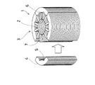
図2は、分割型のモータコア1を示している。 FIG. 2 shows a split type motor core 1.
該モータコア1はステータ側のモータコアを示しており、該モータコア1はティース部2とヨーク部3に分割され、該ヨーク部3は更に円周に沿って所要等分(図示では4等分)され、4つのヨーク4によって構成されている。前記ティース部2及び前記ヨーク4は、それぞれ上記したモータコアの製造方法によって製造されている。
The motor core 1 is a stator-side motor core, and the motor core 1 is divided into a
前記ヨーク部3は円筒形状をしており、内面には中心線と平行に連結溝5が形成されている。
The
又、前記ティース部2は中心円筒部6から前記連結溝5と同数のティース7が、等角度間隔で放射状に形成され、該ティース7の先端が前記連結溝5と嵌合可能となっている。
Further, the
前記モータコア1を組立てる場合は、前記ティース部2に外方からヨーク部3を取付ける。この際、前記ティース7を前記連結溝5に嵌込むことで、前記ティース部2と前記ヨーク部3の位置決め接合が簡単に行える。又、前記ティース部2と前記ヨーク部3との接合は、前記連結溝5と前記ティース7の嵌合のみであり、該ティース7に半径方向の圧縮力は作用せず、又前記ヨーク部3は円周方向に分割されているので、該ヨーク部3にも円周方向の圧縮力は発生しない。従って、前記モータコア1には組立てによる無用の応力の発生がなく、磁気特性を損うことはない。
When the motor core 1 is assembled, the
更に、前記ティース部2、前記ヨーク部3は、積層鋼板が接着剤で一体化され、又積層鋼板間は完全に絶縁されているので、磁気の流れを阻害する要素、磁気を短絡させる要素がなく、鉄損が少なく、磁気特性の優れたモータコア1を構成することができる。
Furthermore, the
1 モータコア
2 ティース部
3 ヨーク部
4 ヨーク
5 連結溝
6 中心円筒部
7 ティース
DESCRIPTION OF SYMBOLS 1
Claims (5)
Priority Applications (1)
| Application Number | Priority Date | Filing Date | Title |
|---|---|---|---|
| JP2004095136A JP2005287134A (en) | 2004-03-29 | 2004-03-29 | Method of manufacturing motor core, motor core and high frequency motor |
Applications Claiming Priority (1)
| Application Number | Priority Date | Filing Date | Title |
|---|---|---|---|
| JP2004095136A JP2005287134A (en) | 2004-03-29 | 2004-03-29 | Method of manufacturing motor core, motor core and high frequency motor |
Publications (1)
| Publication Number | Publication Date |
|---|---|
| JP2005287134A true JP2005287134A (en) | 2005-10-13 |
Family
ID=35184945
Family Applications (1)
| Application Number | Title | Priority Date | Filing Date |
|---|---|---|---|
| JP2004095136A Pending JP2005287134A (en) | 2004-03-29 | 2004-03-29 | Method of manufacturing motor core, motor core and high frequency motor |
Country Status (1)
| Country | Link |
|---|---|
| JP (1) | JP2005287134A (en) |
Cited By (12)
| Publication number | Priority date | Publication date | Assignee | Title |
|---|---|---|---|---|
| KR100739461B1 (en) | 2006-03-21 | 2007-07-13 | 에스앤티대우(주) | A stator of motor for using steering system electric type |
| JP2009038915A (en) * | 2007-08-02 | 2009-02-19 | Aisin Aw Co Ltd | Method for manufacturing stator core |
| JP2011078166A (en) * | 2009-09-29 | 2011-04-14 | Honda Motor Co Ltd | Method of manufacturing core |
| JP2011223844A (en) * | 2010-04-02 | 2011-11-04 | Kazuhiko Goto | Laminating iron core and manufacturing method thereof |
| JP5451934B1 (en) * | 2012-11-06 | 2014-03-26 | 株式会社三井ハイテック | Manufacturing method of laminated iron core |
| JP2014241703A (en) * | 2013-06-12 | 2014-12-25 | 株式会社三井ハイテック | Process of manufacturing laminate iron core |
| WO2015105133A1 (en) * | 2014-01-10 | 2015-07-16 | 株式会社三井ハイテック | Method for manufacturing laminated core |
| US9455612B2 (en) | 2010-12-07 | 2016-09-27 | Mitsui High-Tec, Inc. | Method of manufacturing laminated core |
| US9705369B2 (en) | 2012-10-12 | 2017-07-11 | Mitsui High-Tec, Inc. | Method of resin-sealing laminated core |
| US9947464B2 (en) | 2010-12-14 | 2018-04-17 | Mitsui High-Tec, Inc. | Method of manufacturing laminated core |
| JP6995183B1 (en) | 2020-12-28 | 2022-01-14 | 石田 二彦 | Motor core structure |
| JP2022507823A (en) * | 2018-11-20 | 2022-01-18 | シーアールエス・ホールディングス・リミテッド・ライアビリティ・カンパニー | A method for manufacturing a multi-material segmented stator for rotary electric machines and a stator manufactured by that method. |
-
2004
- 2004-03-29 JP JP2004095136A patent/JP2005287134A/en active Pending
Cited By (22)
| Publication number | Priority date | Publication date | Assignee | Title |
|---|---|---|---|---|
| KR100739461B1 (en) | 2006-03-21 | 2007-07-13 | 에스앤티대우(주) | A stator of motor for using steering system electric type |
| JP2009038915A (en) * | 2007-08-02 | 2009-02-19 | Aisin Aw Co Ltd | Method for manufacturing stator core |
| JP2011078166A (en) * | 2009-09-29 | 2011-04-14 | Honda Motor Co Ltd | Method of manufacturing core |
| JP2011223844A (en) * | 2010-04-02 | 2011-11-04 | Kazuhiko Goto | Laminating iron core and manufacturing method thereof |
| US9455612B2 (en) | 2010-12-07 | 2016-09-27 | Mitsui High-Tec, Inc. | Method of manufacturing laminated core |
| US10177636B2 (en) | 2010-12-07 | 2019-01-08 | Mitsui High-Tec, Inc. | Method of manufacturing laminated core |
| US10283264B2 (en) | 2010-12-14 | 2019-05-07 | Mistui High-Tec, Inc. | Method of manufacturing laminated core |
| US9947464B2 (en) | 2010-12-14 | 2018-04-17 | Mitsui High-Tec, Inc. | Method of manufacturing laminated core |
| US9705369B2 (en) | 2012-10-12 | 2017-07-11 | Mitsui High-Tec, Inc. | Method of resin-sealing laminated core |
| JP5451934B1 (en) * | 2012-11-06 | 2014-03-26 | 株式会社三井ハイテック | Manufacturing method of laminated iron core |
| CN103812285A (en) * | 2012-11-06 | 2014-05-21 | 株式会社三井高科技 | Method for manufacturing laminated core |
| US9564790B2 (en) | 2012-11-06 | 2017-02-07 | Mitsui High-Tec, Inc. | Method for manufacturing laminated core |
| JP2014241703A (en) * | 2013-06-12 | 2014-12-25 | 株式会社三井ハイテック | Process of manufacturing laminate iron core |
| WO2015105133A1 (en) * | 2014-01-10 | 2015-07-16 | 株式会社三井ハイテック | Method for manufacturing laminated core |
| CN105900320A (en) * | 2014-01-10 | 2016-08-24 | 株式会社三井高科技 | Method for manufacturing laminated core |
| JP2015149884A (en) * | 2014-01-10 | 2015-08-20 | 株式会社三井ハイテック | Method of manufacturing laminated core |
| US10418886B2 (en) | 2014-01-10 | 2019-09-17 | Mitsui High-Tec, Inc. | Method for manufacturing laminated core |
| CN105900320B (en) * | 2014-01-10 | 2020-01-17 | 株式会社三井高科技 | Method for manufacturing laminated iron core |
| JP2022507823A (en) * | 2018-11-20 | 2022-01-18 | シーアールエス・ホールディングス・リミテッド・ライアビリティ・カンパニー | A method for manufacturing a multi-material segmented stator for rotary electric machines and a stator manufactured by that method. |
| US11527927B2 (en) | 2018-11-20 | 2022-12-13 | Crs Holdings, Llc | Method of making a multi-material segmented stator for a rotating electric machine and a stator made by said method |
| JP6995183B1 (en) | 2020-12-28 | 2022-01-14 | 石田 二彦 | Motor core structure |
| JP2022103583A (en) * | 2020-12-28 | 2022-07-08 | 石田 二彦 | Motor core structure |
Similar Documents
| Publication | Publication Date | Title |
|---|---|---|
| US7626304B2 (en) | Stator and motor, to which the stator is applied, and method of manufacturing the stator | |
| EP3902122B1 (en) | Laminated core and electric motor | |
| KR20210083337A (en) | Adhesive laminated cores for stators and rotating electric machines | |
| JP7311791B2 (en) | Laminated core and rotating electric machine | |
| CA3131659C (en) | Adhesively-laminated core for stator and electric motor | |
| US20220014051A1 (en) | Laminated core and electric motor | |
| CN109642265B (en) | Thin strip component, method for manufacturing the same, and motor using the thin strip component | |
| JP2005287134A (en) | Method of manufacturing motor core, motor core and high frequency motor | |
| US11915860B2 (en) | Laminated core and electric motor | |
| US20220020521A1 (en) | Adhesively-laminated core for stator and electric motor | |
| JP2019187056A (en) | Core of rotary electric machine, and method of manufacturing core of rotary electric mashine | |
| CN110268608B (en) | Method for manufacturing component for rotating electrical machine | |
| JP2015198475A (en) | rotor core | |
| JP2018182900A (en) | Stator and motor including the same | |
| US20220209592A1 (en) | Core block, laminated core, and electric motor | |
| KR20240052877A (en) | Stator adhesive laminated core and rotating electrical machine | |
| JP2019161766A (en) | Electromagnetic steel sheet | |
| WO2023186859A1 (en) | Rotor for an axial flux machine | |
| EA041718B1 (en) | GLUE-SLATED CORE FOR STATOR AND ELECTRIC MOTOR |