EP1589623A2 - Amplificateur Raman - Google Patents
Amplificateur Raman Download PDFInfo
- Publication number
- EP1589623A2 EP1589623A2 EP05008750A EP05008750A EP1589623A2 EP 1589623 A2 EP1589623 A2 EP 1589623A2 EP 05008750 A EP05008750 A EP 05008750A EP 05008750 A EP05008750 A EP 05008750A EP 1589623 A2 EP1589623 A2 EP 1589623A2
- Authority
- EP
- European Patent Office
- Prior art keywords
- lightwave
- power
- input
- pump
- raman amplifier
- Prior art date
- Legal status (The legal status is an assumption and is not a legal conclusion. Google has not performed a legal analysis and makes no representation as to the accuracy of the status listed.)
- Granted
Links
Images


Classifications
-
- H—ELECTRICITY
- H01—ELECTRIC ELEMENTS
- H01S—DEVICES USING THE PROCESS OF LIGHT AMPLIFICATION BY STIMULATED EMISSION OF RADIATION [LASER] TO AMPLIFY OR GENERATE LIGHT; DEVICES USING STIMULATED EMISSION OF ELECTROMAGNETIC RADIATION IN WAVE RANGES OTHER THAN OPTICAL
- H01S3/00—Lasers, i.e. devices using stimulated emission of electromagnetic radiation in the infrared, visible or ultraviolet wave range
- H01S3/05—Construction or shape of optical resonators; Accommodation of active medium therein; Shape of active medium
- H01S3/06—Construction or shape of active medium
- H01S3/063—Waveguide lasers, i.e. whereby the dimensions of the waveguide are of the order of the light wavelength
- H01S3/067—Fibre lasers
- H01S3/06754—Fibre amplifiers
-
- H—ELECTRICITY
- H01—ELECTRIC ELEMENTS
- H01S—DEVICES USING THE PROCESS OF LIGHT AMPLIFICATION BY STIMULATED EMISSION OF RADIATION [LASER] TO AMPLIFY OR GENERATE LIGHT; DEVICES USING STIMULATED EMISSION OF ELECTROMAGNETIC RADIATION IN WAVE RANGES OTHER THAN OPTICAL
- H01S3/00—Lasers, i.e. devices using stimulated emission of electromagnetic radiation in the infrared, visible or ultraviolet wave range
- H01S3/10—Controlling the intensity, frequency, phase, polarisation or direction of the emitted radiation, e.g. switching, gating, modulating or demodulating
- H01S3/13—Stabilisation of laser output parameters, e.g. frequency or amplitude
- H01S3/1301—Stabilisation of laser output parameters, e.g. frequency or amplitude in optical amplifiers
- H01S3/13013—Stabilisation of laser output parameters, e.g. frequency or amplitude in optical amplifiers by controlling the optical pumping
-
- H—ELECTRICITY
- H01—ELECTRIC ELEMENTS
- H01S—DEVICES USING THE PROCESS OF LIGHT AMPLIFICATION BY STIMULATED EMISSION OF RADIATION [LASER] TO AMPLIFY OR GENERATE LIGHT; DEVICES USING STIMULATED EMISSION OF ELECTROMAGNETIC RADIATION IN WAVE RANGES OTHER THAN OPTICAL
- H01S3/00—Lasers, i.e. devices using stimulated emission of electromagnetic radiation in the infrared, visible or ultraviolet wave range
- H01S3/30—Lasers, i.e. devices using stimulated emission of electromagnetic radiation in the infrared, visible or ultraviolet wave range using scattering effects, e.g. stimulated Brillouin or Raman effects
- H01S3/302—Lasers, i.e. devices using stimulated emission of electromagnetic radiation in the infrared, visible or ultraviolet wave range using scattering effects, e.g. stimulated Brillouin or Raman effects in an optical fibre
-
- H—ELECTRICITY
- H04—ELECTRIC COMMUNICATION TECHNIQUE
- H04B—TRANSMISSION
- H04B10/00—Transmission systems employing electromagnetic waves other than radio-waves, e.g. infrared, visible or ultraviolet light, or employing corpuscular radiation, e.g. quantum communication
- H04B10/29—Repeaters
- H04B10/291—Repeaters in which processing or amplification is carried out without conversion of the main signal from optical form
- H04B10/2912—Repeaters in which processing or amplification is carried out without conversion of the main signal from optical form characterised by the medium used for amplification or processing
- H04B10/2916—Repeaters in which processing or amplification is carried out without conversion of the main signal from optical form characterised by the medium used for amplification or processing using Raman or Brillouin amplifiers
-
- H—ELECTRICITY
- H04—ELECTRIC COMMUNICATION TECHNIQUE
- H04B—TRANSMISSION
- H04B10/00—Transmission systems employing electromagnetic waves other than radio-waves, e.g. infrared, visible or ultraviolet light, or employing corpuscular radiation, e.g. quantum communication
- H04B10/29—Repeaters
- H04B10/291—Repeaters in which processing or amplification is carried out without conversion of the main signal from optical form
- H04B10/293—Signal power control
- H04B10/294—Signal power control in a multiwavelength system, e.g. gain equalisation
- H04B10/296—Transient power control, e.g. due to channel add/drop or rapid fluctuations in the input power
-
- H—ELECTRICITY
- H01—ELECTRIC ELEMENTS
- H01S—DEVICES USING THE PROCESS OF LIGHT AMPLIFICATION BY STIMULATED EMISSION OF RADIATION [LASER] TO AMPLIFY OR GENERATE LIGHT; DEVICES USING STIMULATED EMISSION OF ELECTROMAGNETIC RADIATION IN WAVE RANGES OTHER THAN OPTICAL
- H01S2301/00—Functional characteristics
- H01S2301/04—Gain spectral shaping, flattening
-
- H—ELECTRICITY
- H01—ELECTRIC ELEMENTS
- H01S—DEVICES USING THE PROCESS OF LIGHT AMPLIFICATION BY STIMULATED EMISSION OF RADIATION [LASER] TO AMPLIFY OR GENERATE LIGHT; DEVICES USING STIMULATED EMISSION OF ELECTROMAGNETIC RADIATION IN WAVE RANGES OTHER THAN OPTICAL
- H01S3/00—Lasers, i.e. devices using stimulated emission of electromagnetic radiation in the infrared, visible or ultraviolet wave range
- H01S3/09—Processes or apparatus for excitation, e.g. pumping
- H01S3/091—Processes or apparatus for excitation, e.g. pumping using optical pumping
- H01S3/094—Processes or apparatus for excitation, e.g. pumping using optical pumping by coherent light
- H01S3/094003—Processes or apparatus for excitation, e.g. pumping using optical pumping by coherent light the pumped medium being a fibre
- H01S3/094011—Processes or apparatus for excitation, e.g. pumping using optical pumping by coherent light the pumped medium being a fibre with bidirectional pumping, i.e. with injection of the pump light from both two ends of the fibre
-
- H—ELECTRICITY
- H01—ELECTRIC ELEMENTS
- H01S—DEVICES USING THE PROCESS OF LIGHT AMPLIFICATION BY STIMULATED EMISSION OF RADIATION [LASER] TO AMPLIFY OR GENERATE LIGHT; DEVICES USING STIMULATED EMISSION OF ELECTROMAGNETIC RADIATION IN WAVE RANGES OTHER THAN OPTICAL
- H01S3/00—Lasers, i.e. devices using stimulated emission of electromagnetic radiation in the infrared, visible or ultraviolet wave range
- H01S3/09—Processes or apparatus for excitation, e.g. pumping
- H01S3/091—Processes or apparatus for excitation, e.g. pumping using optical pumping
- H01S3/094—Processes or apparatus for excitation, e.g. pumping using optical pumping by coherent light
- H01S3/094096—Multi-wavelength pumping
-
- H—ELECTRICITY
- H01—ELECTRIC ELEMENTS
- H01S—DEVICES USING THE PROCESS OF LIGHT AMPLIFICATION BY STIMULATED EMISSION OF RADIATION [LASER] TO AMPLIFY OR GENERATE LIGHT; DEVICES USING STIMULATED EMISSION OF ELECTROMAGNETIC RADIATION IN WAVE RANGES OTHER THAN OPTICAL
- H01S3/00—Lasers, i.e. devices using stimulated emission of electromagnetic radiation in the infrared, visible or ultraviolet wave range
- H01S3/10—Controlling the intensity, frequency, phase, polarisation or direction of the emitted radiation, e.g. switching, gating, modulating or demodulating
- H01S3/10007—Controlling the intensity, frequency, phase, polarisation or direction of the emitted radiation, e.g. switching, gating, modulating or demodulating in optical amplifiers
- H01S3/10015—Controlling the intensity, frequency, phase, polarisation or direction of the emitted radiation, e.g. switching, gating, modulating or demodulating in optical amplifiers by monitoring or controlling, e.g. attenuating, the input signal
Definitions
- the present invention relates to a Raman amplifier.
- An object of the present invention is to offer a Raman amplifier that can easily reduce the gain variation in Raman amplification even when the power of an input signal varies.
- the present invention offers a Raman amplifier that is provided with:
- the Raman amplifier may have the following features.
- the Raman amplifier is further provided with an input-power-detecting means that detects the power of the input lightwave, and the control unit performs the following functions:
- the Raman amplifier may have the following features:
- the Raman amplifier may have the following features.
- the Raman amplifier is further provided with:
- the present inventor intensely studied the gain control of the Raman amplification and found that it is possible to reduce the variation in the gain spectrum by controlling only the power of the pump lightwave having the shortest wavelength among the pump lightwaves having a plurality of wavelengths even when the power of the input signal lightwave varies.
- the present invention was accomplished.
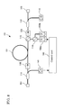
- FIG. 1 is a conceptual diagram showing a Raman amplifier 100 of the first embodiment of the present invention.
- a signal lightwave enters at a light-entering end 101 and is Raman-amplified.
- the Raman-amplified signal lightwave exits from a light-exiting end 102.
- the Raman amplifier 100 is provided with on the signal-lightwave-propagating path from the light-entering end 101 to the light-exiting end 102 a fiber optic coupler 111, an optical isolator 121, a fiber optic coupler 112, a Raman-amplifying optical fiber 130, an optical isolator 122, and a fiber optic coupler 113 in this order.
- the Raman amplifier 100 is provided with a photodiode 141 connected to the fiber optic coupler 111, a fiber optic coupler 114 connected to the fiber optic coupler 112, laser diodes 150a and 150b connected to the fiber optic coupler 114, a photodiode 142 connected to the fiber optic coupler 113, and a control unit 160 connected to the photodiodes 141 and 142 and the laser diode 150a.
- the fiber optic coupler 111 branches a signal lightwave having entered at the light-entering end 101 to send some portion of it to the photodiode 141 and the remaining portion to the optical isolator 121.
- the photodiode 141 receives the signal lightwave having arrived from the fiber optic coupler 111 to produce an electric signal in accordance with the power of the inputted signal lightwave and sends it to the control unit 160.
- the fiber optic coupler 112 receives pump lightwaves having a plurality of wavelengths sent from the fiber optic coupler 114 and sends them to the optical fiber 130.
- the fiber optic coupler 112 receives a signal lightwave having traveled from the fiber optic coupler 111 via the optical isolator 121 and sends it to the optical fiber 130.
- the fiber optic coupler 113 receives a signal lightwave having traveled from the optical fiber 130 via the optical isolator 122 and branches it to send some portion of it to the photodiode 142 and the remaining portion to the light-exiting end 102.
- the photodiode 142 receives the signal lightwave having arrived from the fiber optic coupler 113 to produce an electric signal in accordance with the power of the inputted signal lightwave and sends it to the control unit 160.
- the fiber optic coupler 114 receives pump lightwaves having wavelengths different from each other sent from the laser diodes 150a and 150b. Then, it combines the pump lightwaves and sends the combined pump lightwaves having a plurality of wavelengths to the fiber optic coupler 112.
- the optical isolators 121 and 122 allow lightwaves to pass in a forward direction from the light-entering end 101 to the light-exiting end 102 and prevent them from passing in a backward direction.
- the optical fiber 130 receives pump lightwaves and a signal lightwave both sent from the fiber optic coupler 112 and Raman-amplifies the signal lightwave to send the Raman-amplified signal lightwave to the optical isolator 122.
- the laser diodes 150a and 150b each output a pump lightwave for Raman amplification having a wavelength different from each other.
- the wavelength of the pump lightwave outputted from the laser diode 150a is shorter than that of the pump lightwave outputted from the laser diode 150b.
- the pump lightwave outputted from the laser diode 150a is the pump lightwave having the shortest wavelength among the pump lightwaves having a plurality of wavelengths.
- the control unit 160 receives the electric signals sent from the photodiodes 141 and 142 to control the power of the pump lightwave to be outputted from the laser diode 150a in accordance with these electric signals so that the gain of the Raman amplification can become constant. Specifically, it is desirable that the control unit 160 be structured with an electric circuit for performing the control or the like.
- the laser diodes 150a and 150b and the fiber optic couplers 112 and 114 act as a pump-lightwave-supplying means that supplies pump lightwaves having a plurality of wavelengths to the optical fiber 130.
- the laser diode may be replaced with another laser light source.
- the photodiode 141 and the fiber optic coupler 111 act as an input-power-detecting means that detects the power of the signal lightwave to be inputted into the optical fiber 130.
- the photodiode 142 and the fiber optic coupler 113 act as an output-power-detecting means that detects the power of the output signal lightwave outputted from the optical fiber.
- the Raman amplifier 100 operates as described below. Pump lightwaves outputted from the laser diodes 150a and 150b are combined by the fiber optic coupler 114. The combined pump lightwaves are supplied to the Raman-amplifying optical fiber 130 via the fiber optic coupler 112. A signal lightwave having entered at the light-entering end 101 travels through the fiber optic coupler 111, the optical isolator 121, and the fiber optic coupler 112 and enters the optical fiber 130 to be Raman-amplified there. The Raman-amplified signal lightwave travels through the optical isolator 122 and the fiber optic coupler 113 and exits from the light-exiting end 102.
- the signal lightwave having entered at the light-entering end 101 is branched by the fiber optic coupler 111, and some portion of it is sent to the photodiode 141. Then, the photodiode 141 outputs an electric signal in accordance with the amount of the light it receives.
- the Raman-amplified signal lightwave is branched by the fiber optic coupler 113, and some portion of it is sent to the photodiode 142. Then, the photodiode 142 outputs an electric signal in accordance with the amount of the light it receives.
- the control unit 160 monitors the power of the input signal lightwave in accordance with the electric signal sent from the photodiode 141. It also monitors the power of the output signal lightwave in accordance with the electric signal sent from the photodiode 142. The control unit 160 calculates the gain of the Raman amplification using the monitored powers of the input and output signal lightwaves. Then, it controls the power of the pump lightwave to be outputted from the laser diode 150a so that the gain of the Raman amplification can become constant.
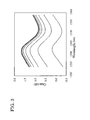
- the optical fiber 130 is a dispersion-compensating fiber having a length of 9.9 km. It is assumed that the center wavelength of the pump lightwave outputted from the laser diode 150a is 1,435.4 nm, and that from the laser diode 150b is 1,462.2 nm. Signal lightwaves are inputted into the Raman amplifier 100 over 32 channels, which are distributed in a band of 1,534.25 to 1,558.98 nm at intervals of 100 GHz in frequency. The signal lightwaves in the individual channels have the same power.
- FIG. 2 is a graph showing a gain spectrum of the Raman amplifier of the first embodiment using the power of the input signal lightwave as a parameter. Even though the power of the input signal lightwave was varied from -32 dBm/ch to -5 dBm/ch (the variation is 27 dB), the gain variation was suppressed to about ⁇ 0.1 dBpp.
- FIG. 3 is a graph showing a gain spectrum of a Raman amplifier of the first embodiment using the power of the input signal lightwave as a parameter when the power of the pump lightwaves was not controlled as Comparative example 1.
- the power of the pump lightwave outputted from each of the laser diodes 150a and 150b was predetermined such that when the power of the input signal lightwave was -5 dBm/ch, the average value of the net gain was about 0 dB and the gain spectrum became more flattened than in any other cases.
- a gain variation of about 1.5 dBpp was produced at the maximum.
- the gain increased as the power of the input signal lightwave decreased.
- the result obtained in the example of the first embodiment shows that even when the power of the input signal lightwave varies, the stability of the gain spectrum can be achieved by controlling only the power of the pump lightwave having the shortest wavelength so that the average gain in the band of the signal lightwave can become constant.
- the first embodiment enables an easy reduction in the gain variation in the Raman amplification.
- the powers of the input and output signal lightwaves are monitored and the obtained values are referred to control the power of the pump lightwave having the shortest wavelength, a more proper control of the gain variation in the Raman amplification can be performed.
- the pump lightwaves having a plurality of wavelengths are supplied to the optical fiber 130 in the same direction as that of the signal lightwave.
- the second embodiment is explained in which the pump lightwaves having a plurality of wavelengths are supplied to the optical fiber 130 in the direction opposite to that of the signal lightwave.
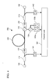
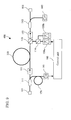
- Figure 4 is a conceptual diagram showing a Raman amplifier 200 of the second embodiment of the present invention.
- a fiber optic coupler 115 for supplying pump lightwaves having a plurality of wavelengths to the optical fiber 130 is placed between the optical fiber 130 and an optical isolator 122 on the path of a signal lightwave.
- the fiber optic coupler 115 receives pump lightwaves having a plurality of wavelengths outputted from the fiber optic coupler 114 and supplies them to the Raman-amphfying optical fiber 130. In addition, the fiber optic coupler 115 receives a signal lightwave outputted from the optical fiber 130 and supplies it to the optical isolator 122.
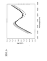
- Figure 5 is a graph showing a gain spectrum of a Raman amplifier of the second embodiment using the power of the input signal lightwave as a parameter. Even though the power of the input signal lightwave was varied from -32 dBm/ch to -5 dBm/ch (the variation is 27 dBm/ch), the gain variation was suppressed to about ⁇ 0.15 dBpp.
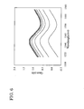
- Figure 6 is a graph showing a gain spectrum of a Raman amplifier of the second embodiment using the power of the input signal lightwave as a parameter when the power of the pump lightwaves was maintained constant as Comparative example 2.
- a gain variation of about 1.0 dBpp was produced at the maximum.
- the comparison of the result with that obtained in the case of the forward pumping shown in Fig. 3 shows that the forward pumping produces a larger amount of variation in gain resulting from the variation in the power of the input signal lightwave. The reason for this is that the Raman amplification by the forward pumping creates gain saturation more readily.
- the present inventor in examining and studying the first and second embodiments and others, found that there is a relationship between the power of the pump lightwave having the shortest wavelength for rendering the gain of the Raman amplification constant and the power of the input signal lightwave.
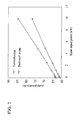
- Figure 7 is a graph showing the relationship between the power of the input signal lightwave and the power of the pump lightwave having the shortest wavelength (the pump lightwave that is outputted from the laser diode 150a and that has a wavelength of 1,435.4 nm) when the pump lightwave having the shortest wavelength is controlled such that the average gain becomes constant in the first and second embodiments.
- the power of the input signal lightwave and the power of the pump lightwave having the shortest wavelength have a relationship expressed as a linear function.
- FIG. 8 is a conceptual diagram showing a Raman amplifier 300 of the third embodiment of the present invention.
- Figure 8 shows that the control unit 160 receives only the electric signal outputted from the photodiode 141.
- the control unit 160 memorizes the above-described relationship and, based on this relationship, calculates the power of the pump lightwave having the shortest wavelength using the monitored power of the input signal lightwave. Then, the control unit 160 controls the power of the pump lightwave to be outputted from the laser diode 150a so that the power can coincide with the calculated value.
- This embodiment demonstrates that the gain variation in the Raman amplification can be easily reduced when the power of the pump lightwave having the shortest wavelength is controlled based on the relationship between the power of the pump lightwave having the shortest wavelength and the power of the input signal lightwave to be established to maintain the gain constant, especially a relationship expressed as a linear function.
- the relationship between the power of the input signal lightwave and the power of the pump lightwave having the shortest wavelength which relationship is expressed as a linear function, is established even in the case of the bidirectional pumping.
- the shortest wavelength of the forward pumping lightwave differs from that of the backward pumping lightwave, only the pump lightwave having a shorter wavelength needs to be controlled.
- the shortest wavelength of the forward pumping lightwave is the same as that of the backward pumping lightwave, both the pump lightwaves having the same shortest wavelength need to be controlled under the condition that they have the same power.
- a Raman-amplifying optical fiber has a length of at least several kilometers, which is longer than that of a rare-earth-doped fiber amplifier. Consequently, it is necessary to design the control system considering the time during which the signal lightwave travels over the Raman-amplifying optical fiber.
- the transient variation in gain can be suppressed by equalizing the time from the variation of the power of the input signal lightwave to the variation of the power of the pump lightwave with the time during which the signal lightwave travels over the Raman-amplifying optical fiber. Therefore, in a backward pumping Raman amplifier, it is desirable that the feedforward control system for controlling the power of the pump lightwave by detecting the power of the input signal lightwave be provided with a retarding means for giving a retarding time that is equal to the time during which the signal lightwave travels over the Raman-amplifying optical fiber. Two types of retarding means are available: one gives a retarding time on an electric circuit, and the other is an optical retarding medium.
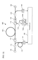
- FIG 9 is a conceptual diagram showing a Raman amplifier 400 of the fourth embodiment of the present invention.
- the Raman amplifier 400 is provided with between the fiber optic coupler 111 and the photodiode 114 a retarding medium 171 for retarding the signal lightwave by a predetermined time.
- the retarding medium 171 it is desirable to use a retarding fiber or the like.
- the predetermined time be a time that gives a proper timing to the control unit 160 for controlling the laser diode 150a in consideration of the time during which the signal lightwave travels over the optical fiber 130.
- the photodiode 141 make reference to the power of the signal lightwave at the instant when a time needed for the signal lightwave to travel over the optical fiber 130 has just elapsed from the instant when the fiber optic coupler 111 outputs the signal lightwave to the retarding fiber 171.
- the above-described structure enables the control of the power of the pump lightwave in consideration of the time during which the signal lightwave travels over the optical fiber 130. As a result, this embodiment can suppress the transient variation in the gain of the Raman amplification.
- the above description is for the backward pumping Raman amplifier.
- the transient variation in the gain can be suppressed by varying the power of the pump lightwave nearly concurrently with the variation in the power of the input signal lightwave.
- a control circuit usually has a response time, it is extremely difficult to control the power of the pump lightwave concurrently with the variation in the power of the input signal lightwave.
- FIG. 10 is a conceptual diagram showing a Raman amplifier 500 of the fifth embodiment of the present invention.
- the Raman amplifier 500 shown in Fig. 10 suppresses the transient variation in the gain in the forward pumping.
- the Raman amplifier 500 is provided with between the fiber optic coupler 111 and the optical isolator 121 a retarding medium 172 for retarding the signal lightwave by a predetermined time.
- the predetermined time be a time that elapses from the instant when the photodiode 141 receives the signal lightwave to the instant when the control unit 160 carries out the control by referring to the power of the inputted signal lightwave.
- the above-described structure can suppress the transient variation in the gain of the Raman amplification because the signal lightwave is inputted into the optical fiber 130 nearly concurrently together with the pump lightwave controlled in accordance with the power of the signal lightwave.
- the Raman amplifier having the above-described structure can perform the control that takes into consideration the time from the detection of the power of the input signal lightwave to the control of the power of the pump lightwave.
- FIG 11 is a conceptual diagram showing a Raman amplifier 600 of the sixth embodiment of the present invention.
- the Raman amplifier 600 shown in Fig. 11 prevents the time difference from occurring in this system.
- the Raman amplifier 600 is provided with between the fiber optic coupler 111 and the photodiode 141 a retarding medium 173 for retarding the signal lightwave by a predetermined time.
- the predetermined time be a time that prevents the occurrence of the time difference between the monitoring of the input signal lightwave and the monitoring of the output signal lightwave.
- the above-described structure can not only suppress the transient variation in the gain of the Raman amplification but also detect the gain with high precision in time.
Landscapes
- Physics & Mathematics (AREA)
- Electromagnetism (AREA)
- Engineering & Computer Science (AREA)
- Plasma & Fusion (AREA)
- Optics & Photonics (AREA)
- Computer Networks & Wireless Communication (AREA)
- Signal Processing (AREA)
- Optical Modulation, Optical Deflection, Nonlinear Optics, Optical Demodulation, Optical Logic Elements (AREA)
- Lasers (AREA)
Applications Claiming Priority (2)
| Application Number | Priority Date | Filing Date | Title |
|---|---|---|---|
| JP2004128889A JP4415746B2 (ja) | 2004-04-23 | 2004-04-23 | ラマン増幅器 |
| JP2004128889 | 2004-04-23 |
Publications (3)
| Publication Number | Publication Date |
|---|---|
| EP1589623A2 true EP1589623A2 (fr) | 2005-10-26 |
| EP1589623A3 EP1589623A3 (fr) | 2006-06-14 |
| EP1589623B1 EP1589623B1 (fr) | 2008-05-07 |
Family
ID=34935523
Family Applications (1)
| Application Number | Title | Priority Date | Filing Date |
|---|---|---|---|
| EP05008750A Ceased EP1589623B1 (fr) | 2004-04-23 | 2005-04-21 | Amplificateur Raman |
Country Status (6)
| Country | Link |
|---|---|
| US (1) | US6987608B2 (fr) |
| EP (1) | EP1589623B1 (fr) |
| JP (1) | JP4415746B2 (fr) |
| CN (1) | CN1691553B (fr) |
| CA (1) | CA2504022C (fr) |
| DE (1) | DE602005006464D1 (fr) |
Cited By (2)
| Publication number | Priority date | Publication date | Assignee | Title |
|---|---|---|---|---|
| WO2007130319A3 (fr) * | 2006-05-02 | 2008-02-28 | At & T Corp | contrÔle dynamique de gain avec retour amÉliorÉ pour circuit WDM employant des amplificateurs À fibres de raman À pompage en multiples longueurs d'onde |
| US11317807B2 (en) | 2018-10-15 | 2022-05-03 | Hi Llc | Detection of fast-neural signal using depth-resolved spectroscopy via intensity modulated interferometry having tunable pump laser |
Families Citing this family (13)
| Publication number | Priority date | Publication date | Assignee | Title |
|---|---|---|---|---|
| US7619812B2 (en) * | 2004-08-11 | 2009-11-17 | Siemens Aktiengesellschaft | Method and arrangement for the rapid adjustment of the tilt of optical WDM signals |
| US7672042B2 (en) * | 2005-02-24 | 2010-03-02 | At&T Corporation | Fast dynamic gain control in an optical fiber amplifier |
| US7436582B2 (en) * | 2005-11-15 | 2008-10-14 | At&T Corp. | Fast dynamic gain control in a bidirectionally-pumped Raman fiber amplifier |
| US7142356B2 (en) * | 2005-02-24 | 2006-11-28 | At&T Corp. | Fast dynamic gain control in an optical fiber amplifier |
| US20070109623A1 (en) * | 2005-11-15 | 2007-05-17 | At&T Corp. | Fast Dynamic Gain Control in a Bidirectionally-Pumped Raman Fiber Amplifier |
| US7280270B2 (en) * | 2005-11-15 | 2007-10-09 | At&T Corporation | Fast dynamic gain control in cascaded Raman fiber amplifiers |
| US7277221B2 (en) * | 2005-11-15 | 2007-10-02 | At&T Corp. | Fast dynamic gain control in cascaded Raman fiber amplifiers |
| JP5347333B2 (ja) * | 2008-05-23 | 2013-11-20 | 富士通株式会社 | 光信号処理装置 |
| JP5841517B2 (ja) * | 2012-09-28 | 2016-01-13 | 日本電信電話株式会社 | 光ファイバ増幅器システム及び光ファイバ増幅方法 |
| EP3370307B1 (fr) * | 2015-10-30 | 2021-09-22 | Fujikura Ltd. | Système de laser à fibre optique, procédés d'évaluation et d'amélioration de résistance à la réflexion de celui-ci, et laser à fibre optique |
| CN106229800A (zh) * | 2016-08-15 | 2016-12-14 | 桂林创研科技有限公司 | 新型掺铒光纤放大器 |
| CN111490444B (zh) * | 2020-04-08 | 2022-07-15 | 武汉光迅科技股份有限公司 | 脉冲光纤放大器及光信号功率放大方法 |
| JP7810891B2 (ja) | 2022-04-21 | 2026-02-04 | 1Finity株式会社 | ラマン増幅装置、ラマン増幅方法、及びラマン増幅システム |
Family Cites Families (9)
| Publication number | Priority date | Publication date | Assignee | Title |
|---|---|---|---|---|
| JP3527671B2 (ja) * | 1999-04-23 | 2004-05-17 | 富士通株式会社 | ラマン増幅による光伝送パワーの波長特性制御方法、並びに、それを用いた波長多重光通信システムおよび光増幅器 |
| JP2001223646A (ja) * | 2000-02-07 | 2001-08-17 | Nec Corp | 光増幅中継器とこれを用いた光伝送装置 |
| US6366395B1 (en) * | 2000-03-30 | 2002-04-02 | Nortel Networks Limited | Optical amplifier gain control |
| JP2002040495A (ja) * | 2000-07-21 | 2002-02-06 | Sumitomo Electric Ind Ltd | ラマン増幅器 |
| GB2383209A (en) * | 2001-12-12 | 2003-06-18 | Robert Charles Goodfellow | Raman optical amplifier with two power control loops |
| US7016104B2 (en) * | 2002-07-01 | 2006-03-21 | Jds Uniphase Corporation | Wider dynamic range to a FBG stabilized pump |
| US6963681B2 (en) * | 2002-07-01 | 2005-11-08 | Jds Uniphase Corporation | Automatic raman gain control |
| US6813067B1 (en) * | 2002-11-05 | 2004-11-02 | At&T Corp. | Method and apparatus for providing a broadband raman amplifier with improved noise performance |
| EP1503528B1 (fr) * | 2003-04-03 | 2016-05-18 | Mitsubishi Denki Kabushiki Kaisha | Amplificateur optique et systeme de communication optique |
-
2004
- 2004-04-23 JP JP2004128889A patent/JP4415746B2/ja not_active Expired - Fee Related
-
2005
- 2005-04-13 CA CA2504022A patent/CA2504022C/fr not_active Expired - Fee Related
- 2005-04-18 US US11/107,741 patent/US6987608B2/en not_active Expired - Lifetime
- 2005-04-21 EP EP05008750A patent/EP1589623B1/fr not_active Ceased
- 2005-04-21 DE DE602005006464T patent/DE602005006464D1/de not_active Expired - Lifetime
- 2005-04-22 CN CN2005100676890A patent/CN1691553B/zh not_active Expired - Fee Related
Cited By (3)
| Publication number | Priority date | Publication date | Assignee | Title |
|---|---|---|---|---|
| WO2007130319A3 (fr) * | 2006-05-02 | 2008-02-28 | At & T Corp | contrÔle dynamique de gain avec retour amÉliorÉ pour circuit WDM employant des amplificateurs À fibres de raman À pompage en multiples longueurs d'onde |
| US7916384B2 (en) | 2006-05-02 | 2011-03-29 | At&T Intellectual Property Ii, L.P. | Feedback dynamic gain control for a WDM system employing multi wavelength pumped Raman fiber amplifiers |
| US11317807B2 (en) | 2018-10-15 | 2022-05-03 | Hi Llc | Detection of fast-neural signal using depth-resolved spectroscopy via intensity modulated interferometry having tunable pump laser |
Also Published As
| Publication number | Publication date |
|---|---|
| CA2504022A1 (fr) | 2005-10-23 |
| EP1589623B1 (fr) | 2008-05-07 |
| JP2005309250A (ja) | 2005-11-04 |
| JP4415746B2 (ja) | 2010-02-17 |
| DE602005006464D1 (de) | 2008-06-19 |
| CN1691553B (zh) | 2010-08-11 |
| CA2504022C (fr) | 2013-07-16 |
| US20050237601A1 (en) | 2005-10-27 |
| CN1691553A (zh) | 2005-11-02 |
| US6987608B2 (en) | 2006-01-17 |
| EP1589623A3 (fr) | 2006-06-14 |
Similar Documents
| Publication | Publication Date | Title |
|---|---|---|
| US5995275A (en) | Doped fiber amplifier using bidirectional pumping with pump lights having different frequencies | |
| US5912760A (en) | Light amplifier | |
| US6700696B2 (en) | High order fiber Raman amplifiers | |
| JP3442897B2 (ja) | 範囲別利得制御光増幅器及び範囲別光増幅器利得制御方法及び光受信器及び光中継器 | |
| EP1589623B1 (fr) | Amplificateur Raman | |
| JP3652804B2 (ja) | 光伝送装置 | |
| JP2004120669A (ja) | 光受信器 | |
| US6624927B1 (en) | Raman optical amplifiers | |
| US6823107B2 (en) | Method and device for optical amplification | |
| CA2365544A1 (fr) | Amplificateurs optiques raman d'ordre eleve | |
| JP3655508B2 (ja) | ラマン増幅器及び光通信システム | |
| US8027082B2 (en) | Raman amplifier and excitation light source used thereof | |
| JP2001094181A (ja) | 光増幅器 | |
| US7336415B2 (en) | Optical amplification module, optical amplification apparatus, and optical communications system | |
| US7133192B2 (en) | Light amplification control unit and method | |
| US6417960B1 (en) | Method of equalizing gain utilizing asymmetrical loss-wavelength characteristics and optical amplifying apparatus using same | |
| JP4337545B2 (ja) | 光通信システム | |
| US7177073B2 (en) | Multiple order Raman amplifier | |
| US9215009B2 (en) | Light output control apparatus | |
| JP3977363B2 (ja) | ラマン増幅器及び光通信システム | |
| WO2002013423A2 (fr) | Amplificateurs raman a fibre d'ordre eleve | |
| JP2004048028A (ja) | 光増幅モジュール、光増幅器及び光通信システム | |
| US8477030B2 (en) | Optical amplifier module and dispersion compensation fiber loss detection method | |
| US20040208585A1 (en) | Systems and methods for minimizing signal power and providing reduced Raman pump depletion for WDM optical system | |
| US20040032640A1 (en) | Optical transmission system and optical amplification method |
Legal Events
| Date | Code | Title | Description |
|---|---|---|---|
| PUAI | Public reference made under article 153(3) epc to a published international application that has entered the european phase |
Free format text: ORIGINAL CODE: 0009012 |
|
| AK | Designated contracting states |
Kind code of ref document: A2 Designated state(s): AT BE BG CH CY CZ DE DK EE ES FI FR GB GR HU IE IS IT LI LT LU MC NL PL PT RO SE SI SK TR |
|
| AX | Request for extension of the european patent |
Extension state: AL BA HR LV MK YU |
|
| PUAL | Search report despatched |
Free format text: ORIGINAL CODE: 0009013 |
|
| AK | Designated contracting states |
Kind code of ref document: A3 Designated state(s): AT BE BG CH CY CZ DE DK EE ES FI FR GB GR HU IE IS IT LI LT LU MC NL PL PT RO SE SI SK TR |
|
| AX | Request for extension of the european patent |
Extension state: AL BA HR LV MK YU |
|
| RIC1 | Information provided on ipc code assigned before grant |
Ipc: H01S 3/131 20060101ALN20060509BHEP Ipc: H01S 3/13 20060101ALI20060509BHEP Ipc: H01S 3/067 20060101ALN20060509BHEP Ipc: H01S 3/30 20060101ALN20060509BHEP Ipc: H04B 10/17 20060101AFI20060509BHEP Ipc: H01S 3/094 20060101ALN20060509BHEP |
|
| 17P | Request for examination filed |
Effective date: 20060908 |
|
| 17Q | First examination report despatched |
Effective date: 20061106 |
|
| AKX | Designation fees paid |
Designated state(s): DE FR GB IT |
|
| GRAP | Despatch of communication of intention to grant a patent |
Free format text: ORIGINAL CODE: EPIDOSNIGR1 |
|
| RIN1 | Information on inventor provided before grant (corrected) |
Inventor name: NAKAJI, HARUO,C/O YOKOHAMA WORKS OF SUMITOMO |
|
| GRAS | Grant fee paid |
Free format text: ORIGINAL CODE: EPIDOSNIGR3 |
|
| GRAA | (expected) grant |
Free format text: ORIGINAL CODE: 0009210 |
|
| AK | Designated contracting states |
Kind code of ref document: B1 Designated state(s): DE FR GB IT |
|
| REG | Reference to a national code |
Ref country code: GB Ref legal event code: FG4D |
|
| REF | Corresponds to: |
Ref document number: 602005006464 Country of ref document: DE Date of ref document: 20080619 Kind code of ref document: P |
|
| PLBE | No opposition filed within time limit |
Free format text: ORIGINAL CODE: 0009261 |
|
| STAA | Information on the status of an ep patent application or granted ep patent |
Free format text: STATUS: NO OPPOSITION FILED WITHIN TIME LIMIT |
|
| 26N | No opposition filed |
Effective date: 20090210 |
|
| REG | Reference to a national code |
Ref country code: FR Ref legal event code: PLFP Year of fee payment: 12 |
|
| REG | Reference to a national code |
Ref country code: FR Ref legal event code: PLFP Year of fee payment: 13 |
|
| REG | Reference to a national code |
Ref country code: FR Ref legal event code: PLFP Year of fee payment: 14 |
|
| PGFP | Annual fee paid to national office [announced via postgrant information from national office to epo] |
Ref country code: FR Payment date: 20190313 Year of fee payment: 15 |
|
| PGFP | Annual fee paid to national office [announced via postgrant information from national office to epo] |
Ref country code: IT Payment date: 20190419 Year of fee payment: 15 Ref country code: DE Payment date: 20190410 Year of fee payment: 15 |
|
| PGFP | Annual fee paid to national office [announced via postgrant information from national office to epo] |
Ref country code: GB Payment date: 20190417 Year of fee payment: 15 |
|
| REG | Reference to a national code |
Ref country code: DE Ref legal event code: R119 Ref document number: 602005006464 Country of ref document: DE |
|
| PG25 | Lapsed in a contracting state [announced via postgrant information from national office to epo] |
Ref country code: DE Free format text: LAPSE BECAUSE OF NON-PAYMENT OF DUE FEES Effective date: 20201103 Ref country code: FR Free format text: LAPSE BECAUSE OF NON-PAYMENT OF DUE FEES Effective date: 20200430 |
|
| GBPC | Gb: european patent ceased through non-payment of renewal fee |
Effective date: 20200421 |
|
| PG25 | Lapsed in a contracting state [announced via postgrant information from national office to epo] |
Ref country code: GB Free format text: LAPSE BECAUSE OF NON-PAYMENT OF DUE FEES Effective date: 20200421 |
|
| PG25 | Lapsed in a contracting state [announced via postgrant information from national office to epo] |
Ref country code: IT Free format text: LAPSE BECAUSE OF NON-PAYMENT OF DUE FEES Effective date: 20200421 |