EP1589484B1 - Procédé pour la détection et/ou le suivi d'objets - Google Patents
Procédé pour la détection et/ou le suivi d'objets Download PDFInfo
- Publication number
- EP1589484B1 EP1589484B1 EP05007965A EP05007965A EP1589484B1 EP 1589484 B1 EP1589484 B1 EP 1589484B1 EP 05007965 A EP05007965 A EP 05007965A EP 05007965 A EP05007965 A EP 05007965A EP 1589484 B1 EP1589484 B1 EP 1589484B1
- Authority
- EP
- European Patent Office
- Prior art keywords
- image
- current
- cycle
- earlier
- images
- Prior art date
- Legal status (The legal status is an assumption and is not a legal conclusion. Google has not performed a legal analysis and makes no representation as to the accuracy of the status listed.)
- Expired - Lifetime
Links
Images


Classifications
-
- G—PHYSICS
- G01—MEASURING; TESTING
- G01S—RADIO DIRECTION-FINDING; RADIO NAVIGATION; DETERMINING DISTANCE OR VELOCITY BY USE OF RADIO WAVES; LOCATING OR PRESENCE-DETECTING BY USE OF THE REFLECTION OR RERADIATION OF RADIO WAVES; ANALOGOUS ARRANGEMENTS USING OTHER WAVES
- G01S17/00—Systems using the reflection or reradiation of electromagnetic waves other than radio waves, e.g. lidar systems
- G01S17/86—Combinations of lidar systems with systems other than lidar, radar or sonar, e.g. with direction finders
-
- G—PHYSICS
- G01—MEASURING; TESTING
- G01S—RADIO DIRECTION-FINDING; RADIO NAVIGATION; DETERMINING DISTANCE OR VELOCITY BY USE OF RADIO WAVES; LOCATING OR PRESENCE-DETECTING BY USE OF THE REFLECTION OR RERADIATION OF RADIO WAVES; ANALOGOUS ARRANGEMENTS USING OTHER WAVES
- G01S17/00—Systems using the reflection or reradiation of electromagnetic waves other than radio waves, e.g. lidar systems
- G01S17/88—Lidar systems specially adapted for specific applications
- G01S17/93—Lidar systems specially adapted for specific applications for anti-collision purposes
- G01S17/931—Lidar systems specially adapted for specific applications for anti-collision purposes of land vehicles
-
- G—PHYSICS
- G06—COMPUTING OR CALCULATING; COUNTING
- G06T—IMAGE DATA PROCESSING OR GENERATION, IN GENERAL
- G06T7/00—Image analysis
- G06T7/20—Analysis of motion
- G06T7/246—Analysis of motion using feature-based methods, e.g. the tracking of corners or segments
- G06T7/251—Analysis of motion using feature-based methods, e.g. the tracking of corners or segments involving models
-
- G—PHYSICS
- G06—COMPUTING OR CALCULATING; COUNTING
- G06T—IMAGE DATA PROCESSING OR GENERATION, IN GENERAL
- G06T7/00—Image analysis
- G06T7/20—Analysis of motion
- G06T7/269—Analysis of motion using gradient-based methods
-
- G—PHYSICS
- G06—COMPUTING OR CALCULATING; COUNTING
- G06V—IMAGE OR VIDEO RECOGNITION OR UNDERSTANDING
- G06V20/00—Scenes; Scene-specific elements
- G06V20/50—Context or environment of the image
- G06V20/56—Context or environment of the image exterior to a vehicle by using sensors mounted on the vehicle
- G06V20/58—Recognition of moving objects or obstacles, e.g. vehicles or pedestrians; Recognition of traffic objects, e.g. traffic signs, traffic lights or roads
-
- G—PHYSICS
- G06—COMPUTING OR CALCULATING; COUNTING
- G06T—IMAGE DATA PROCESSING OR GENERATION, IN GENERAL
- G06T2207/00—Indexing scheme for image analysis or image enhancement
- G06T2207/10—Image acquisition modality
- G06T2207/10016—Video; Image sequence
- G06T2207/10021—Stereoscopic video; Stereoscopic image sequence
-
- G—PHYSICS
- G06—COMPUTING OR CALCULATING; COUNTING
- G06T—IMAGE DATA PROCESSING OR GENERATION, IN GENERAL
- G06T2207/00—Indexing scheme for image analysis or image enhancement
- G06T2207/10—Image acquisition modality
- G06T2207/10028—Range image; Depth image; 3D point clouds
-
- G—PHYSICS
- G06—COMPUTING OR CALCULATING; COUNTING
- G06T—IMAGE DATA PROCESSING OR GENERATION, IN GENERAL
- G06T2207/00—Indexing scheme for image analysis or image enhancement
- G06T2207/30—Subject of image; Context of image processing
- G06T2207/30196—Human being; Person
-
- G—PHYSICS
- G06—COMPUTING OR CALCULATING; COUNTING
- G06T—IMAGE DATA PROCESSING OR GENERATION, IN GENERAL
- G06T2207/00—Indexing scheme for image analysis or image enhancement
- G06T2207/30—Subject of image; Context of image processing
- G06T2207/30241—Trajectory
-
- G—PHYSICS
- G06—COMPUTING OR CALCULATING; COUNTING
- G06T—IMAGE DATA PROCESSING OR GENERATION, IN GENERAL
- G06T2207/00—Indexing scheme for image analysis or image enhancement
- G06T2207/30—Subject of image; Context of image processing
- G06T2207/30248—Vehicle exterior or interior
- G06T2207/30252—Vehicle exterior; Vicinity of vehicle
Definitions
- the present invention relates to a method for detecting and tracking objects that correspond to objects in a detection range of an electromagnetic radiation sensor, and to an apparatus for performing the method.
- Images of a detection area are detected at constant time intervals by a sensor for electromagnetic radiation, for example a laser scanner or a video camera.
- the images are then searched for objects that correspond to objects in the detection area. If an object was found for the first time in a picture, this object is searched for in subsequent cycles of the method in order to be able to track its position or positional change over time. This is often predicated on the basis of the position and speed of an object in a previous cycle, its location for a current cycle or in a current image, then then found in the image in the vicinity of the predicated position of the object elements, such as segments, the object from the previous cycle and to be able to record its current position.
- Such methods are suitable, for example, for monitoring an area in front of and / or next to a motor vehicle.
- a potential advantage can be the automatic detection of sudden dangers and the introduction of appropriate countermeasures. For this purpose, however, it is necessary that objects can be detected very quickly and accurately tracked.
- the accuracy of the detected object properties will often increase, as in the course of the tracking, further information about the object can be collected allowing for better characterization of the object or state of the object. Accordingly, inaccuracies may occur especially when new objects appear in images.
- this may be, for example, pedestrians who, covered by another object such as, for example, a motor vehicle parked on the edge of a roadway, suddenly appear on the road and can only then be detected by the sensor.
- the same problem can occur when pedestrians are positioned in front of an object so that the object tracking process combines the pedestrian and the object into an object so that the pedestrian is not recognized until he has moved far enough away from the object.
- US Pat. No. 6,480,615 B1 describes a method of tracking objects in which the optical flow of an image field is determined using data from three consecutively captured images k-1, k, k + 1. On the basis of a parameter S it is decided whether the gradients required for the determination of the optical flow from the images k-1 and k or from the images k and k + 1 are used. Due to the possibility of using gradients on the pictures k-1 and k, the optical flux can also be determined in areas which are temporarily hidden by a foreground object.
- Object is associated with at least a portion of an earlier image and / or at least one of an earlier state of the object or an object corresponding thereto determined using a corresponding previous image in the current cycle.
- the device according to the invention for detecting and tracking objects has at least one sensor for electromagnetic radiation, which is designed to detect images of a detection area, and a data processing device connected to the at least one sensor, which is designed to carry out the method according to the invention and in particular means for evaluating current images of the at least one sensor, means for determining parts of a current image as a result of at least preliminary evaluation of the current image or for detecting an object in the current cycle and means for assignment parts of an earlier image and / or for determining at least one indication of an earlier state of the object or an object corresponding thereto using a corresponding previous image in the current cycle and associating the indication with the part of the current image or the current object includes.
- the method according to the invention serves to detect and track objects in a detection area.
- This can basically be stationary or move, which can be the case in particular when the images are detected by means of a sensor attached to a vehicle.
- the images are captured by at least one electromagnetic radiation sensor.
- the sensor may be a purely passive sensor that receives only electromagnetic radiation. However, a sensor may also be used which can be reflected by a source of particularly directional, radiatable electromagnetic radiation which can be reflected from an illuminated point or area on an object and at least one corresponding one reflected from an object point or region Radiation sensitive sensor element has. You can also continue Combinations of electromagnetic radiation sensors are used which detect different types of images. The detection ranges of the sensors then need not necessarily overlap, but it is preferred that these overlap at least partially.
- an image is in particular also understood to mean a set of data which respectively reproduce the position of a point or area on one or more objects detected by the sensor in at least one direction transverse to a viewing direction of the sensor and at least one property of the object point or area
- the position of the object point can be given, for example, when detecting object points in a scanning plane by an angle with respect to any, but fixed predetermined reference direction, for example, the sensor.
- the layers may be given by layers of sensor elements of the sensor and optionally imaging properties.
- the property may be, for example, the intensity and / or wavelength or color of the emitted optical radiation, the distance from the sensor or also the speed in the radial direction relative to the sensor.
- video images may contain data on the intensity of radiated optical radiation as a property and with respect to a sensor element that has detected the radiation of an object point or area, and thus with respect to a location, while range images as properties of the detected object points or areas the distance from the sensor and, as position information, may include an angle at which the subject point or range was detected.
- speed pictures Finally, data on the speed of the object points or areas relative to the sensor.
- the images need not be detected directly by a single sensor. Rather, it is also possible to combine at least two temporally associated images, which were detected by at least two electromagnetic radiation sensors, to form an overall image that reflects a larger detection area or additional characteristics of object points or areas. For example, from two images captured by two spaced-apart video cameras, taking into account the imaging characteristics and the arrangement of the video cameras, distance images may be generated which also include data in addition to a distance of an object point from a reference point fixed relative to the video cameras with respect to the intensity or color of the light emitted by the respective object point or area.
- video and distance images can be processed together, without being summarized in a narrow sense to a set of image data.
- the images used in the method according to the invention are recorded at successive times, these preferably having a constant time interval from one another.
- the sensor of the device according to the invention is therefore for the repeated detection of Images of the coverage area shown. If several images are used for one cycle, they are preferably detected substantially synchronously, ie their detection times differ by a smaller time span than that between successive samples by the sensor with the lowest detection rate.
- the acquired images are then evaluated in successive cycles, with at least one corresponding image being evaluated in a given cycle. If several images are recorded essentially synchronously, it is sufficient for one of the images to be evaluated at least provisionally.
- At least one object found in a cycle on the basis of at least one corresponding image is searched in a later cycle in a corresponding later image in order to be tracked.
- conventional object recognition and tracking methods can be used for this purpose.
- an assignment of pixels of the current cycle to objects detected in a previous cycle or image can take place.
- a prediction method may be used in which a position in the current cycle is predicated on the basis of the position of at least one object in an earlier cycle, in particular in a preceding cycle and its velocity, and the object is searched for in the vicinity of the predicted position.
- New objects may be formed from portions of an image, ie, pixels or sets of pixels, in particular segments, determined in the cycle that could not be associated with previously known objects.
- At least one portion of a current image determined in the current cycle or one recognized in the current cycle Object is associated with at least a portion of an earlier image and / or at least one of an earlier state of the object or an object corresponding thereto determined based on a corresponding earlier image.
- At least one criterion can be checked, by means of which a decision is made as to whether an earlier image should be used or not. This then means that if the criterion is not met, an otherwise known object recognition and tracking can take place.
- a part of a current image is determined, which may be a pixel or a set of pixels, for example at least one segment, determined in the current cycle. If several current images are used in a current cycle, the image that has been preliminarily evaluated does not necessarily have to match the image from which a part is determined. However, an object in the current image can also be recognized and used. Both the determination of the part of the image and the recognition of the object can be carried out first with method steps that are similar to those in conventional methods.
- the part of the current image or the object in the current cycle determined in the at least preliminary evaluation can then be assigned a part of the previous image, which in turn is a pixel or a set of pixels determined in the current cycle, for example at least one Segment, the previous image can act.
- the parts of the images may each have different numbers of pixels, so that no one-to-one assignment of pixels needs to be given.
- images are understood to mean an assignment of a part of a first image or of a first object to a part of a second image or of a second object that specifies the part of the second image or the second object, and for this a suitable part of a first part suitable first object from possibly several alternatives selected and assigned.
- the part of the current image or object in the current cycle may also be assigned an indication relating to the object or object corresponding thereto.
- This information can be values of arbitrary state variables of an object or object, for example the position, speed, shape, size, assignment to one of several object classes, into which objects are classified according to their properties relevant for object tracking, or else the presence of the object at all.
- the determination it is not necessary to use the entire previous image, but the determination can also be limited to subareas.
- at least one pixel of the previous image which may preferably still be stored for this purpose during the current cycle, and at the same time the result of the at least preliminary evaluation of the current image are used for the determination.
- a portion of the previous image or an item derived from the previous image be associated with a portion of the current image or an object of the current cycle and not portions of the current image with objects or indicia derived from the previous image were won.
- the data obtained by the method may then be output or stored to be used by subsequent means, for example, to control a vehicle.
- a data processing device is provided in the device according to the invention, which is connected to the sensor for electromagnetic radiation for the transmission of images.
- the data processing device can be wholly or partially formed as a non-programmable circuit, which increases the execution speed.
- the data processing device preferably has a processor which can be programmed to carry out the method according to the invention and, connected thereto, a memory, an output interface and an input section to the sensor.
- means for evaluating current images of the sensor means for determining parts of a current image as a result of at least preliminary evaluation of the current image or for detecting an object in the current cycle and / or the assignment of Part of an earlier image, or means for determining at least one indication relating to an earlier state of the object or an object corresponding thereto on the basis of a corresponding earlier image and associating the indication with the part of the current image or the current object, which may be formed wholly or partially as not freely programmable electrical circuit, but preferably be formed by a suitably programmed processor.
- a sensor for any electromagnetic radiation can be used.
- at least one radar sensor in particular a spatially resolving radar sensor, is used as the sensor.
- preferably spatially resolved images of a radar sensor are used. Radar sensors, in particular, can directly detect radial speeds of objects relative to the radar sensor.
- At least one optical radiation sensor i. Radiation in the infrared, visible or even ultraviolet range of the electromagnetic spectrum used.
- Such sensors generally have a better spatial resolution than radar sensors.
- sensors for detecting distance images For example, a stereo video camera system with at least two video cameras are used, which are spaced apart in a plane in which a distance is detected by the stereo video camera system.
- sensors are used in which at least one scanning beam is used with electromagnetic radiation for scanning at least one scanning plane.
- a plurality of scanning beams can be used for substantially simultaneous scanning of stripes in a scanning plane, or, preferably, a scanning beam can be pivoted in the scanning plane, wherein radiation reflected from articles is received by a corresponding detector.
- corresponding laser scanners can be used, by means of which at least one pulsed laser beam can be detected over a detection range, reflected by an object reflected radiation of the pulsed laser beam and based on the duration of a pulse of the laser beam to the object and back to the laser scanner, a distance of the object determined angular resolution ,
- Such laser scanners are characterized by a good spatial resolution with a high detection rate.
- Particularly preferred are laser scanners are used, which scan several fan-like stacked scanning planes.
- video images are used in the method according to the invention and that the device according to the invention for capturing video images comprises a video system which can comprise at least one video camera comprising an imaging optics and a sensor system for spatially resolved reception of optical radiation, for example visible light Light and / or infrared radiation having.
- a video camera depending on the application, in particular a wide-angle angle or a panoramic camera are used.
- a video camera with a telephoto lens is particularly suitable.
- video cameras with zoom lenses can also be used.
- a black-and-white or grayscale system or even a color-sensitive system can be used as the sensor system. In this case, for example, corresponding CCD or CMOS sensor elements can be used.
- the assignment of the portion of the previous image or the indication of the previous state of the object be used to determine another indication of the current state of an object
- the additional information determined does not need to refer to the object for which the information was determined in relation to its previous state. Rather, it can be any object of the current cycle.
- at least sections of recursively operating method in which starting from information from the at least preliminary evaluation of a current image initially new information about an object or object is obtained at a time corresponding to an earlier image, which in turn for the evaluation of current picture is used. This will be the existing information exploited much more effectively in the pictures than in exclusively linearly operating methods.
- a current location of the new object in the current cycle is determined based on the current location of the new object being an earlier location of the new object in an earlier cycle, and that using the estimated earlier location of the new object, the current value of a state quantity of the new object in the current cycle is determined.
- the state quantity can be estimated as the speed of the object, which otherwise can not be determined on the basis of only one image.
- a current size and / or shape is determined for the new object in the current cycle, and that the current size and / or shape are used in the check for occlusion.
- the size and / or shape of the new object may serve to first classify it into one of several classes of objects, each comprising items having properties characteristic of object recognition and tracking. For example, object classes for pedestrians, motor vehicles, roadway boundaries or the like may be provided. Depending on the object classes, it can then be estimated whether the object is in the existing time between the detection of the current image and the previous image with the maximum possible for objects of the object class speed from a hidden by the other object area in the detected position could have moved.
- the occlusion check be determined whether an object corresponding to this new object was already present at a previous time in the detection range of the sensor.
- the information about the new object in the previous cycle obtained in the current cycle can be used to estimate its velocity as a state quantity in the current cycle in both direction and magnitude. This is particularly useful, for example, to quickly detect pedestrians who are hidden by parked cars and suddenly emerge from behind the vehicle, and then, if necessary, be able to react to them.
- an object newly recognized in a current image may not have been recognized for any reason other than occlusion in the previous cycle.
- the new object be searched in an earlier image, and that upon finding the object in the previous image in the current cycle, a current value of at least one state size for the object and / or another object using a previous one Value of the state size for the new object and / or the other object in the previous cycle is determined.
- the search can be facilitated by the fact that properties of the object, such as its size and / or outline or shape from the current cycle are already known.
- properties of the object such as its size and / or outline or shape from the current cycle are already known.
- the new object exists must have been, so that in the evaluation of the earlier image in the previous cycle possibly existing uncertainties in the assignment of parts of an image, such as pixels or segments, can be eliminated to objects.
- Such an uncertainty can occur in particular if, in the earlier image, two object objects or regions belonging to two different objects are actually recognized as belonging to an object. If the new object is found again in the previous picture, then information can be obtained both about the new object or the one object corresponding to it and another object corresponding to the other object now newly determined for the previous cycle. In particular, for the new object or the other object as a state variable in the earlier cycle, its positions and possibly sizes and / or shapes can be determined. By using appropriate data for the current cycle, on the one hand, for the object that is initially new in the current cycle, a speed can already be determined and, on the other hand, a more accurate speed can be determined for the other object that corresponds to the other object in the preceding cycle.
- pedestrians for example, can be detected very easily, for example, who, as far as the sensor is concerned, have stopped directly in front of an object on the edge of the roadway and have then stepped on the roadway.
- recognition of the pedestrian in a current image can then by the temporal tracing its speed both in terms of their size and their direction be estimated so that valuable time can be gained in the detection of the pedestrian.
- the search for the new object in the previous image can be done in different ways.
- the images are segmented with a predetermined segmentation method and with at least one corresponding predetermined segmentation parameter, and that for finding the new object in the earlier image, at least one corresponding region of the former image with another segmentation method and / or is segmented again with a changed segmentation parameter.
- a new assignment of the newly determined segments to corresponding objects can take place.
- the resegmentation does not need to be for the entire image, but may preferably extend only to the area determined by the location of the new object in the current cycle and corresponding nearby other objects depending on their velocities, such that detection of other objects is not affected.
- Both the segmentation method used and the possibly changed segmentation parameters can be adapted in particular situationally, i. be selected depending on the layers, types or sizes and / or the number of corresponding pixels of the new object and the other object.
- temporally associated distance and video images are used, for example, by a laser scanner for detecting Distance images and a video camera for capturing video images or by a video system for generating stereo images with at least two spaced-apart, coupled to each other coupled video cameras can be detected.
- video image processing to reduce processing overhead is controlled by evaluating corresponding range images, ie, attention control of video image processing by the laser scanner, features and / or objects are only searched in those areas of the video image that include portions in which the corresponding range image Subject points or areas corresponding pixels were detected.
- the regions may be formed by strips extending in a direction orthogonal to a scanning plane, whose intersection with the detection region of the sensor for detecting the distance images is defined in its position and width by at least one distance pixel or multiple removal pixels.
- An object is not detected in the video image until it enters the detection range of the distance image acquisition sensor.
- a laser scanner to scan the range images by scanning a plane of the detection area by means of a laser beam swept in a scan plane
- an object may be recognizable in a video image, although not yet in the range image due, for example, to masking at the scan plane level. is recognizable.
- temporally associated distance and video images of at least one common subarea of the coverage area be used, that in video images for objects and / or features is searched only in subsections that are determined in dependence on temporally associated range pixels that in a current cycle upon detection of a new object and / or feature, the new object and / or feature in the video image is traced back in time to an earlier cycle and that a location of the object corresponding to the new object and / or feature in the previous cycle is determined using the information about an object and / or feature corresponding to the object in the previous video image.
- the temporally associated distance and video images used in this case are preferably detected substantially synchronously, ie their acquisition times differ by a smaller time span than that between successive scans by the sensor with the lowest acquisition rate.
- the subsections can be given in particular by areas of predetermined shape and size around the distance pixels, preferably the aforementioned strips orthogonal to a scanning plane. For distance pixels in the range image, it is thus possible to search for at least one corresponding feature or an entire object in the video image in the corresponding subsection of the video image. When using only features tracing is usually faster to carry out.
- the determination of the position of the object corresponding to the new object or feature in the earlier cycle can be effected, in particular, by an estimation, which is preferably based on the position of the corresponding feature and / or object in the video image. Furthermore, from the position of the object corresponding to the new object or feature in the previous cycle and the position of the new object or feature in the current cycle, its speed can be determined in the current cycle. In this process variant In particular, it can be exploited that objects can often already be detected by a video camera if they do not yet represent, for example, the height of the detection range of the sensor, in the range images which usually only have a lower extent, ie flatter detection range are recognizable for the Entfemungsulph.
- temporally related range and video images of at least a common portion of the coverage area are used.
- Distance pixels in an earlier range image are assigned distance pixels in a current range image for at least one range corresponding to a range pixel in the previous range image and / or at least one range pixel a displacement and / or displacement speed, in particular an optical flow, is determined in the earlier distance image corresponding feature of the corresponding previous video image and / or the current video image, and is, the displacement or displacement speed, in particular the optical flow, for assigning a Distance pixels in the current range image to the range pixel in the former range image used for objects in the Entternungstruck that approach a distance image sensing sensor and / or in a current cycle more distance pixels than in an earlier cycle, distance pixels in the current cycle under Using the corresponding displacement of the region or feature, in particular the corresponding optical flow, distance pixels are assigned in the previous cycle.
- Linking information from range images to information from corresponding video images thereby additionally providing data for at least one range pixel that can be used in processing the range pixels.
- areas detected on the object are usually moved during a movement of an object in the distance image and the video image. If the areas in the video image have an intensity profile or corresponding features, the movement of the object manifests itself approximately as a displacement of the corresponding intensity profiles or features in the video image.
- a displacement is understood to mean a displacement between successive cycles, which, however, does not necessarily have to follow each other directly.
- the motion information from the video images can then be assigned to the corresponding areas of the object or corresponding distance pixels.
- a corresponding optical flux is used to determine the displacement of the region determined.
- an image plane can be used in which the video pixels of the video image then defined in the plane lie.
- an area is used which is used in the context of a camera model for the treatment of a video image.
- an optical flux can be determined for at least one distance pixel. Namely, in general, there may be the case where range pixels are detected on object surfaces which have no intensity structure and for which therefore an optical flux can not be detected.
- the optical flow can be completely determined, for example, if the corresponding region of the video image has a change in the intensity in two linearly independent directions.
- a corresponding tracking is therefore based on these areas.
- the optical flow does not necessarily have to be calculated for the entire video image. Rather, it is sufficient to determine this for the distance pixel corresponding object point or - if necessary - its environment.
- the place in the definition of optical surface used for the optical flow is calculated from the position coordinates of the distance pixel, the relative position of the sensor used to capture the distance images to the video system used to capture the video images, the imaging geometry of the video system or a video camera or a model for this and the given area, on which the optical flux is to be determined, derivable.
- a corresponding video pixel can be used as the location, but it is also possible to determine the optical flow with subpixel precision at locations between video pixels or pixels of the video image.
- This method which removes itself from the sensor or objects having a non-large number of range pixels in the current cycle, therefore has the advantage that a prediction of the object positions does not need to take place, since the use of the displacement or the optical flow is an individual tracking Distance pixels allowed.
- the reverse procedure for approaching objects or objects having more range pixels in the current cycle than in an earlier cycle has the advantage that an assignment of a larger number of range pixels to a smaller number of range pixels, in particular in situations where objects in the current cycle are close to each other, it can be done with greater certainty.
- a more accurate speed can be assigned to the corresponding object since an averaging over corresponding velocities of mutually associated distance pixels can be used to determine the speed of the object and a larger number of such distance pixels are available in the current cycle.
- the object recognition and tracking is carried out on the basis of video images, and that in the object recognition the detection of objects takes place on the basis of filtered video images, which have a reduced resolution due to the filtering, and that upon detection of an object in the current cycle based on the location and optionally shape of the object in the current filtered video image, searching for an object corresponding to the object in an earlier video image whose resolution is higher than that of the filtered video image; upon finding a corresponding object in the previous video image, corresponding data about the object is used in the evaluation of the current video image.
- object recognition and tracking may be assisted by the use of range images.
- Filtering can be any method that reduces the number of pixels in the video image. In the simplest case, for example, simply undertaking an undersampling of the image are used in which of square blocks of pixels or pixels in each case only one pixel or pixels representative of the whole arrangement. If a distant object approaches the sensor used to capture the video image, it may happen that only very few pixels or pixels are available in the filtered video image during the first detection of the object.
- the invention also relates to a computer program with program code means for carrying out the method according to the invention when the program is executed on a computer.
- a further subject of the invention is also a computer program product with program code means which are stored on a computer-readable data carrier in order to carry out the method according to the invention when the computer program product is executed on a computer.
- a computer means any data processing device, in particular a data processing device of the device according to the invention, with which the method can be carried out.
- this can be a digital signal processor and / or have microprocessor with which the method is carried out in whole or in part.
- the invention is preferably suitable for monitoring areas with movable objects, in particular road traffic, wherein the acquisition of the images can be effected by at least one stationary sensor and / or a sensor held on a vehicle.
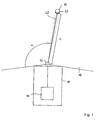
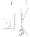
- a vehicle 10 carries at its front a laser scanner 12 and a connected via a data line to the laser scanner 12 data processing device 14, which forms together with the laser scanner 12, an apparatus for detecting and tracking objects according to a first preferred embodiment of the invention.
- a vehicle 10 carries at its front a laser scanner 12 and a connected via a data line to the laser scanner 12 data processing device 14, which forms together with the laser scanner 12, an apparatus for detecting and tracking objects according to a first preferred embodiment of the invention.
- Fig. 1 In the direction of travel in front of the vehicle is an in Fig. 1 only very schematically shown person 16, which is considered within the scope of the invention for the sake of simplicity as an object.
- the laser scanner 12 By means of the laser scanner 12 is an in Fig. 1 only partially shown detection range 18 scanned, which is due to the mounting position of the laser scanner 12 on the front side of the vehicle 10 is arranged symmetrically to the longitudinal axis of the vehicle 10 and covers an angle of slightly more than 180 °.
- the detection area 18 is in Fig. 1 shown only schematically and for clarity, especially in the radial direction too small.
- the laser scanner 12 scans its detection range 18 in a basically known manner with a pulsating laser beam bundle 20 rotating at a constant angular velocity, wherein the same time, at constant time intervals ⁇ t at times ⁇ i in fixed angle ranges around a mean angle ⁇ i , the laser radiation beam 20 is detected from a point 22 or area of an object, for example the person 16, is reflected.
- the index i runs from 1 to the number of angular ranges in the detection range 18. From these angle ranges is in Fig. 1 only an angular range is shown, which is associated with the mean angle ⁇ i . Here, however, the angle range is shown exaggerated for clarity.
- the detection area 18 is substantially two-dimensional, except for the widening of the laser beam 20, and essentially forms, i. to the diameter of the laser beam 20, a scanning plane.
- the distance d i of the object point 22 is determined by the laser scanner 12.
- the laser scanner 12 therefore detects, as coordinates in a distance pixel corresponding to the object point 22 of the object or the person 16, the angle ⁇ i and the distance d i determined at this angle, ie the position of the object point 22 in polar coordinates. Each detected object point is therefore assigned a distance pixel.
- the amount of range pixels acquired in the one scan forms a range image in the sense of the present application.
- the laser scanner 12 scans the detection area 18 in successive scans with time intervals ⁇ t, so that a temporal sequence of scans and corresponding distance images arises.
- the processing of the distance images of the laser scanner 12 is carried out by the data processing device 14.
- the data processing device 14 has u.a. via a digital signal processor programmed for carrying out the method according to the invention with a corresponding computer program according to the invention and a memory device connected to the digital signal processor.
- the data processing device may also have a conventional processor with which a computer program according to the invention stored in the data processing device is executed for carrying out the method according to the invention.
- the programmed data processing device provides means for evaluating current images of the sensor, means for determining parts of a current image as a result of at least preliminary evaluation of the current image or for recognizing an object in the current cycle and means for assigning parts of a current image previous image and / or for determining at least one indication relating to an earlier state of the object or an object corresponding thereto on the basis of a corresponding earlier image and assignment of the information to the part of the current image or the current object.
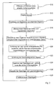
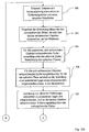
- the in Fig. 2 illustrated method performed according to a first preferred embodiment of the invention.
- a range image is acquired by scanning the detection area 18 and read into a memory in the data processing device 14.
- step S 10 a preprocessing of the distance image data is carried out, in which, optionally after correction of the data, a transformation of the position coordinates of the distance image points into a Cartesian, permanently connected to the vehicle 10 vehicle coordinate system is performed.
- step S 12 the distance image is then segmented.
- sets of range pixels are formed in a manner known per se, which are characterized in that each range pixel of an amount of at least one other range pixel of the same quantity has a mean square distance that is smaller than a predetermined segmentation distance.
- An amount thus formed corresponds to one segment each.
- a segment can also be formed by a single distance pixel, which has a mean square distance of all other distance pixels of the current distance image, which is greater than the predetermined segmentation distance.
- step S14 which is not performed in the very first cycle of the method, then an assignment of segments to objects already detected in an earlier cycle of the method takes place, by which methods known per se can be used. In the present method, this is done for each object known in the previous cycle used an object position predicted in step S28 of the previous cycle.
- a segment of the current cycle is assigned to a corresponding object of the previous cycle if at least one of the range pixels of the segment from the object in the predicated object position has a distance less than one of an uncertainty of prediction and magnitude and Orientation of the object in the previous cycle dependent maximum distance.
- step S 16 new objects are then formed from segments which could not be assigned to objects known from the previous cycle, and a position of the object in the current cycle is determined from the positions of the distance pixels constituting the segments.
- step S 18 after checking whether new objects have been found, it is checked whether in the preceding cycle a subject corresponding to a newly formed object in a previous range image or cycle may be recognized by an already recognized one in the previous cycle Object corresponding object could be obscured.
- the processing of the current distance image in steps S 10 to S 16 including the check in step S 18 whether a new object has been found represents an at least preliminary evaluation of the current image.
- FIGS. 3A and 3B This is exemplary in the FIGS. 3A and 3B in which in sections of successive distance images, a vehicle 24, which is only partially represented by the black solid line, and a symbolized by a rectangle 26 pedestrian, which moves at a speed v with respect to the vehicle 24 are shown.
- the individual points represent distance pixels of the corresponding distance images.
- the laser scanner 12 in the coordinate origin, ie in the point (0,0), wherein the coordinate axes of the Cartesian coordinate system in any, but fixed selected distance units are divided.
- FIG. 3A a previous distance image
- the pedestrian 26 is hidden from view of the laser scanner 12 of the vehicle 24 and therefore not detectable in the distance image.
- Fig. 3B in which the current distance image is shown, the pedestrian 24 has moved away behind the vehicle 24 and is now detected by the laser scanner 12 for the first time.
- the contours of the objects corresponding to the objects 24 and 26 are in FIGS. 3A and 3B each with a dashed line Compensation curve given by the distance pixels. It is easy to see that in Fig. 3B the contour of the vehicle 24 corresponding object is greater than that of the pedestrian 26 corresponding object.
- the further detection of occlusion preferably takes place adaptive to the situation, ie as a function of the speeds of the already recognized objects in the preceding cycle.
- the pedestrian 26 corresponding object can be found or no other object has a smaller distance to this and the pedestrian 26 corresponding object due the size may not correspond to a very fast moving object, the article or pedestrian 26 in the earlier image was very likely to be obscured by the vehicle 24.
- step S20 the location of objects covered in the previous range image of hidden objects corresponding to new objects is estimated as an indication with respect to an earlier state of the respective new objects according to the invention.
- a minimum speed of the object or pedestrian 26 is used to estimate the position in the previous distance image in Fig. 3A
- the subject or pedestrian 26 was just not visible at the time the range image was acquired, so that an object box surrounding it in the current range image, whose size is specified in the pedestrian-type object method, just does not have its edge laser radiation beam 20 could be detected.
- the results in Fig. 4 the estimated position of the pedestrian 26 given by the dotted rectangle in the previous distance image or cycle shifted by the displacement vector d from the position in the current distance image or cycle.
- step S22 the velocity of the objects is then estimated by determining the change in the location of an object in the previous image and the current image, using the estimated location for the new objects if they were obscured.
- the estimated velocity of the objects then results both with respect to the direction and the magnitude of the velocity by dividing the change in position given by the displacement vector d by the time duration ⁇ t between successive scans of the detection region 18.
- step S24 the determined object positions and sizes and the current distance image, which must be available in the following cycle as the then preceding distance image, are then stored, whereby the preceding distance image is deleted.
- step S26 the object positions and speeds are output to corresponding further processing devices.
- step S28 a prediction of new object positions for the following cycle is performed at the end of the current cycle.
- the prediction of the position of the object as well as the determination of the uncertainty of the prediction can be done for example in a known manner by means of a Kalman filter.
- initialization of the Kalman filter for this object can be done with much more accurate data, which greatly facilitates subsequent object recognition and tracking.
- step S10 Thereafter, the next cycle may begin with step S10.
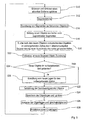
- a method for recognizing and tracking objects according to a second preferred embodiment of the invention is schematically illustrated in the flowchart in FIG Fig. 5 shown. It differs from the method according to the first embodiment in that newly detected objects are treated differently in a current cycle, so that the steps S 10 to S 16 and S22 to S28 are the same as in the above-described embodiment and the embodiments there apply accordingly also here.
- the apparatus for tracking and recognizing objects with the method according to the second preferred embodiment of the invention is only so compared with the corresponding apparatus in the first embodiment changed that the processed in the data processing device 14 program is modified accordingly, ie in particular that the means for assigning parts of an earlier image and / or for determining at least one indication with respect to a previous state of the object or a corresponding item on the Based on a corresponding earlier image and assignment of the specification to the part of the current image or the current object, are modified.
- step S30 after the formation of new objects from previously unallocated segments in step S 16 in step S30, after checking the criterion, whether a new object has ever been found in the current one , searched for the new objects corresponding objects or objects in the previous distance image. It is assumed that the new object could not be found in the previous cycle or distance image because it could not be recognized as an independent object due to the segmentation and object formation or segment-object assignment.
- FIGS. 6A to 6G illustrates in each of which sections of successive distance images are shown.
- the laser scanner 12 is again arranged in the distance images in the origin (0,0) of the coordinate system, which corresponds to the Cartesian coordinate system of the previous embodiment.
- a pedestrian 26 moves from the perspective of the laser scanner 12, initially immediately in front of a parked vehicle 24 at a speed v to get into the Figs. 6F and 6G finally to be removed from the vehicle 24 so far that it can be recognized as a stand-alone object with the normal segmentation method.
- the segmentation can not separate the distance pixels corresponding to the vehicle 24 from the range pixels corresponding to the pedestrian 26.
- the objects are determined which correspond to the new object corresponding to the pedestrian 26 in the current, the distance image in FIG Fig. 6F the next cycle. In the example, this is only the object corresponding to the vehicle 24.
- the steps up to this stage correspond to an at least preliminary evaluation of the current distance image in the sense of the invention.
- the range pixels of the segments in the previous range image or cycle are re-segmented to form the respective objects previously re-segmented in the previous cycle.
- these are all distance pixels of the section of the distance image in Fig. 6E .
- the segmentation method used in step S 12 is used, but with a reduced segmentation distance.
- the segmentation distance can be fixed.
- the segmentation distance is selected as a function of the detected size of at least one of the detected objects, preferably of the smallest, so that a situationally adapted segmentation can take place.
- step S32 a new assignment of segments to the objects affected by the re-segmentation is performed in step S32.
- objects already known in the previous cycle their position and speed in the preceding cycle are used in conjunction with the orientation, shape and size determined in the current cycle as well as for the new object of its shape and size determined in the current cycle.
- step S34 it is then checked whether new or changed objects were found in the preceding distance image. If this is not the case, the method is continued with step S22.
- step S36 a location of the object corresponding to the new object and the changed object in the preceding distance image is determined.
- the new object is then treated as a known object whose location in the previous cycle is known, for which purpose corresponding changes in data structures of the program are carried out and a corresponding Kalman filter for the previous cycle is subsequently initialized. Furthermore, for the changed object re-prediction of the location for the current cycle done to improve the accuracy of the Kalman filter.
- object positions for the preceding cycle and the current cycle are obtained for objects known in the previous cycle and newly found in step S32, so that an estimate of the velocity of these objects can now be made in step S22, the object positions in the preceding one Distance image or cycle can be used.
- the methods of the first two embodiments can be combined. For example, only a test according to Step S30 and, if no new objects were found in step S34, concealment detection according to the first embodiment.
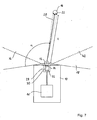
- a vehicle 10 which carries an apparatus for detecting and tracking objects according to a third preferred embodiment of the invention.
- the device for detecting and tracking objects differs from the device for detecting and tracking objects in the first embodiment in that in addition to the laser scanner 12, a video system 30 is provided which, like the laser scanner 12, via a corresponding data connection with a is compared to the data processing device 14 in the first embodiment modified data processing device 14 'is connected.
- a video system 30 is provided which, like the laser scanner 12, via a corresponding data connection with a is compared to the data processing device 14 in the first embodiment modified data processing device 14 'is connected.
- the video system 28 has a monocular video camera 30, which is a conventional black-and-white video camera having a CCD area sensor 32 and an imaging device incorporated in the Fig. 7 and 8th is shown schematically as a simple lens 34, but in fact consists of a lens system, and from a detection range 36 of the video system incident light on the CCD area sensor 32 images.
- An optical axis 38 of the video camera 30 is in a small, in Fig. 8 exaggeratedly large angle shown on the through the pivoting plane of the laser beam bundle 20 given scanning plane 40 of the laser scanner 12 to inclined.
- the CCD area sensor 32 has arrayed photodetection elements that are cyclically read to form video images with video pixels.
- the video images initially contain, for each pixel, the position of the photodetection elements in the matrix or a different identifier for the photodetection elements and a respective intensity value corresponding to the intensity of the light received by the corresponding photodetection element.
- the video images are acquired substantially synchronously with the distance images and thus at the same rate with which distance images are also acquired by the laser scanner 12.
- the focal length can be calculated from the location of an object point, such as the object point 22 on the person 16, on which location of the CCD Flat sensor 32 and which of the arranged as a matrix photodetection elements of the object point is mapped.
- the position of a photodetection element may be indicated by the short dashed lines in FIG Fig. 7 and Fig. 8 indicated light cone in which object points or areas must lie, from which detected radiation can fall on the photodetection element.
- a corresponding camera model can be used.
- the example is a well-known pinhole camera model.
- a common detection area 42 is in the Fig. 7 and 8th schematically represented by a dotted line and given by the section of the detection area 18 of the laser scanner 12 and the detection area 36 of the video system 28.
- the data processing device 14 'differs from the data processing device 14 on the one hand in that interfaces are provided to be substantially synchronous, ie within a time period that is significantly shorter than the time period ⁇ t between successive scans of the detection area 18 of the laser scanner 12, respectively To read in distance image and a current video image of the video system 28.
- the processor is programmed with a computer program according to a third preferred embodiment of the invention for carrying out a method according to a third preferred embodiment of the invention.
- the data processing device 14 comprises means for evaluating current images of the sensor, means for determining parts of a current image as a result of at least preliminary evaluation of the current image or for detecting an object in the current cycle and means for assigning parts of an earlier image and or for determining at least one indication relating to an earlier state of the object or an object corresponding thereto on the basis of a corresponding state previous image and assignment of the indication to the part of the current image or the current object in the sense of the invention.
- the in Fig. 9 illustrated method performed according to the third preferred embodiment of the invention.
- features in the video images are recognized and tracked, but video image processing is done on the basis of distance images for computation time by searching for features only in those portions of the video image in which range pixels of the range image and corresponding subject areas are located.
- step S38 a current distance image and a current video image are read in and preprocessed.
- the reading and the preprocessing of the images can be carried out independently of each other for the two images in parallel or in any order.
- the positional pixels in the distance image are supplemented by a positional component determined by the scanning plane 40 in which the object points corresponding to the distance picture elements form to form a complete positional coordinate set in three dimensions. With the location of a distance pixel, the position defined by these coordinates will be referred to below.
- the data of the video image is transformed into the vehicle coordinate system in which the distance pixels are also defined.
- a rectification of the video image data for example for the removal of distortions, and a transformation of the video pixels to an image plane is performed.
- the video pixels can then be assigned positions in the vehicle coordinate system in a corresponding plane.
- the current distance image and the current video image are stored for further use.
- step S 12 as in the first embodiment, the range image is then segmented.
- step S40 features are detected in the video image, wherein only areas are used by the video image in which the distance image according to a segment in the distance image corresponding object must be detectable. More precisely, the detection takes place only in strips of the video image which extend substantially perpendicular to the scanning plane of the laser scanner 12 and which in each case correspond to a segment of the distance image and which have video image points corresponding to the distance pixels in the segments.
- the strips are defined to extend in a direction orthogonal to the scanning plane 40 of the laser scanner 12 over the entire extent of the video image and have a width in the orthogonal direction determined to be the same for all the distance pixels of a segment corresponding video pixels in the respective Stripes lie. These video pixels can be determined by using the camera model.
- the strips each have predetermined edge areas in width on both sides of the respective outermost video picture elements. Since other parts of the video image are initially ignored, there is an attention control of the video image processing.
- an assignment in the features found in the current video image to characteristics known from the previous cycle continues to take place using a position of the respective features predicted in each case for the current cycle in step S49 of the preceding cycle.
- positions of the features in the current cycle are determined.
- step S41 it is then checked whether new features were found that could not be assigned to features not known from the previous cycle.
- step S42 a search is performed in step S42 for features corresponding to the new features in the preceding video image by a backward tracking.
- known methods of video image processing can be used.
- step S44 the location of a feature corresponding to the new feature in the previous video image is then determined.
- the determined feature locations and speeds are then output in step S26 after storage for further use.
- step S48 the current video image is then stored after the previous video image has been deleted.
- step S49 new feature layers are now predicted, so that an assignment of features in step S40 in the following cycle to objects is facilitated.
- the now known speeds or a Kalman filter can be used.
- a subsequent or supplementary evaluation of a preceding video image thus takes place.
- the results of this evaluation, the feature found or its location in the previous video image, are then used in the current cycle to determine the speed of the current feature.
- Figs. 10A and 10B and Figs. 11A and 11B The use of the method for the detection of suddenly behind parked vehicles prominent pedestrians is in the Figs. 10A and 10B and Figs. 11A and 11B, respectively.
- the Fig. 10A and 11A each show a section of successive, of the laser scanner 12th detected distance image at the level of the scanning plane 40, while the Fig. 10B and 11B Extracts from correspondingly substantially synchronously recorded with the video system 28 video images.
- the scanning plane 40 of the laser scanner 12 is shown by a dotted line. Furthermore, this corresponds to the Figs. 10A and 10B used Cartesian coordinate system in the previous embodiments.
- the pedestrian as in the Figs. 10A and 10B shown not detectable by the laser scanner 12, since it is covered by the vehicle 44.
- the detection area 36 of the video system 28 in the direction perpendicular to the scanning plane 40 has a larger opening angle than the detection area 18 of the laser scanner 12, the pedestrian 46 can already be seen in the corresponding video image. Due to the attention control, however, this is not detected in the video image since it is displayed in the distance image (cf. Fig. 10A ) is covered.
- the pedestrian 46 moves in the example at a speed v to the right, he is no longer covered by the vehicle 44 after some time, resulting in the Figs. 11A and 11B is shown.
- the pedestrian 46 can be detected in the range image so that it is also detected in the video image via the attention control. While nothing would be known about this in a conventional video image processing other than the location of the pedestrian 46, in the method traced in the video images of the embodiment of the pedestrian 46, where he in the in Fig. 10B shown video images can be recognized.
- the position thus determined in the earlier video image now makes it possible to determine the speed of the pedestrian 46, which was initially recognized only in the current video image, even at its first detection or recognition. Since the tracing only occurs when finding new features, the execution speed of the method is only slightly reduced on average.
- substantially the same object recognition and tracing apparatus as in the third embodiment is used, but the programming of the data processing means 14 'according to the changed method is also changed.
- This also means that the means for assigning parts of an earlier image and / or for determining at least one indication with respect to an earlier state of the object or an object corresponding thereto on the basis of a corresponding earlier image and assignment of the indication to the part of current picture or the current object are modified.
- range pixels in successively acquired range images are tracked using the optical flux in corresponding areas in video images acquired substantially synchronously with the range images.
- step S50 of a current cycle a current distance image and a current video image are first acquired and read into the data processing device in which preprocessing of these images takes place in accordance with step S38 in the preceding embodiment.
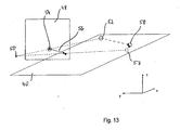
- the transformation of the video pixels is modified from the step S38 in the previous embodiment in that the transformation of the video pixels to an image plane 48 used for defining or calculating an optical flow (cf. Fig. 13 ) is carried out.
- a modified pinhole camera model for the video camera 30 which is basically known to the person skilled in the art is used, which is characterized by the position of an optical center 50 and the image plane 48 is defined, which serves as a surface for defining or determining the optical flow.
- the location of the optical center 50 is determined using the imaging geometry of the video camera 30, in particular the position relative to the laser scanner 12 and the focal length of the lens 34, determined.
- the pinhole camera model is modified for simplicity in that the image plane 48 is located at a fixed position between the optical center 50 and the object points, relative to the video system 28 on the vehicle 10 Fig. 13 the points 52 and 58, and by mirroring the actual image plane at the optical center 50 emerges from this.
- step S52 which is omitted in the first cycle of the method, first all distance pixels of the cycle immediately preceding the current cycle are determined which correspond to objects that are removed from the sensor or laser scanner 12. For the sake of simplicity, these distance pixels are referred to as removal pixels corresponding distance pixels.
- corresponding distance image points from the cycle directly preceding the current cycle are then calculated and stored for use in the current cycle in the image plane corresponding to respective video image points in the image plane 48.
- Fig. 13 illustrates geometrically, the position results in each case by the intersection 54 of an extending through the distance pixel, in the distance pixel 52, and the optical center 50 degrees with the image plane 48th
- step S54 which is likewise omitted in the first cycle, then for all projected distance pixels of the preceding cycle or corresponding intersections corresponding to the objects moving away from the laser scanner 12, corresponding actual optical flow vectors, hereinafter also referred to as optical flows, determined on the basis of the video image from the immediately preceding cycle and from the current cycle and converted by multiplication with the cycle duration or the reciprocal of the sampling frequency into a displacement vector.
- Fig. 13 this is shown for the range pixel 52, for which at the intersection 54 an optical flux vector is determined which lies in the image plane 48 and which, after scaling with the cycle time, results in a displacement vector 56 beginning at the intersection 54.
- optical flow is determined by means of a differential method, in this example the " Performance of optical flow techniques "by JL Barren, DJ Fleed and SS Beauchemin, International Journal of Computer Vision, 12 (1), pp. 43-77 (1994) described by Luke and Canade.
- a position of a corresponding object point predicted by the optical flow in the current cycle in the scanning plane 40 is then determined in step S56.
- Geometric in Fig. 13 For this purpose, the intersection point 57 of a straight line passing through the optical center 50 and the end point of the displacement vector 56 with the scanning plane 40 is determined.
- step S58 current distance pixels, in Fig. 13
- the current range pixel 58 the current range image associated with predicted locations and corresponding distance pixels of the previous image or cycle, if possible.
- an assignment criterion for example, can be used are assigned to the one current distance pixel whose quadratic distance between the predicted position and the actual current position is minimal compared to those of other current range pixels.
- step S60 the unassigned distance pixels of the current cycle, which must therefore correspond to objects not removing from the laser scanner 12, are projected onto the image plane 48, which is analogous to the projection in step S52.
- optical flows are then calculated in step S62 analogously to step S54.
- a traced position of a corresponding object point in the scanning plane 40 is now determined in step S64.
- the determination of the traced position is carried out analogously to the determination of the predicted position in step S56, but as a displacement vector, a corresponding opposite to the optical flow corresponding vector is used.
- step S66 then an assignment of distance pixels of the previous cycle, which correspond to non-sensor-removing objects, then predetermined, traced layers and corresponding unassigned distance pixels of the current cycle in step S64.
- the assignment can be made according to a corresponding scheme, as in step S58, but now predetermined distance pixels of the current cycle or corresponding traced layers are assigned distance pixels of the previous distance image.
- distance pixels of the previous cycle and of the current cycle or image are assigned to one another, wherein the assignment for objects removing from the laser scanner 12 takes place such that current range pixels are assigned to range pixels of the preceding frame while the remaining range pixels of the preceding frame which are not assigned to objects removing from the sensor or laser scanner 12, are assigned to the unassigned distance pixels of the current cycle and distance image or their traced layers.
- step S68 a segmentation of the current distance image corresponding to the segmentation in step S 12 of the first embodiment is now performed.
- step S70 a segment-object mapping is then performed using the association of range pixels of the previous range image and the current range image and the association between range pixels of the previous range image and objects of the previous cycle.
- step S72 object properties, in particular their positions and speeds, are determined and output.
- the method may then proceed to step S50 in the next cycle.
- a prediction step can be eliminated by using the optical flow.
- the projection can be done in other ways, examples of which are described in the aforementioned patent application.
- a corresponding device for object recognition and tracking according to a fourth preferred embodiment of the invention therefore comprises a video system as used in the previous embodiment and the preceding other method, the video camera of which is connected to a data processing device as in the previous embodiment and the preceding other method, but which are suitable for carrying out the method is programmed according to the fourth preferred embodiment.
- This also means that the means for assigning parts of an earlier image and / or for determining at least one indication with respect to an earlier state of the object or an object corresponding thereto on the basis of a corresponding earlier image and assignment of the indication to the part of current picture or the current object are modified.
- the laser scanner 12 is eliminated.
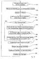
- a current video image is first detected and read in step S74 in a current cycle.
- a corresponding preprocessing of the video image data can take place.
- step S76 in order to increase the processing speed, the read-in video image is subjected to image resolution reducing filtering, which in the present embodiment consists of using only the pixel in the lower left corner of 4x4 blocks of video pixels.
- step S78 then objects in the subsampled video image are detected.
- conventional methods of object recognition and tracking in video images can be used.
- step S80 the detected objects are now assigned to objects from the previous cycle.
- the assignment is made in the example based on predicted object positions for the current cycle, which were determined in the previous cycle in a step S94, by means of known association methods.
- step S82 it is checked whether new objects were detected which were not to be assigned to any of the objects of the previous cycle. If no new objects were detected, the process continues to step S90.
- step S84 in the previous video image which is not sub-sampled in the example or half as strong as the image generated in step S76, is searched for an object that corresponds to a new object.
- FIG. 15A For example, the person is schematically represented in a current full resolution video image, with black rectangles representing video pixels corresponding to the person. Due to the above-mentioned subsampling, the in Fig. 15B shown subsampled video image in which the person is represented only by four individual pixels. If the person has now approached the video camera from a greater distance, it can do so in the previous one Video image at full resolution, for example, the in Fig. 16 shown size, wherein after subsampling no pixel survives, by means of which a corresponding object could be detected.
- the new object is searched for in the previous image in full resolution and not in the reduced resolution, which therefore can also be found. Nevertheless, since the new object can only occur near the object detected in the current video image, the computation time for recognizing the object in the previous video image is greatly reduced.
- step S88 the objects corresponding to the new objects in the previous video image are tracked into the current cycle, which is easily possible since the corresponding object has already been detected in the subsampled current video image.
- step S90 Based on the determined positions of the objects in the preceding video image and thus in the previous cycle and in the current cycle, it is now possible to determine speeds of the objects by estimation or difference formation in step S90.
- step S92 the current video image is then stored, erasing the previous video image.
- step S94 an output of the object positions and velocities is made for use in the following applications.
- step S96 new object locations are predicted for the following cycle, in the vicinity of which objects in the video image of the following cycle are searched for.
- a Kalman filter can be used again.
- the method according to the fourth embodiment allows on the one hand by the sub-sampling a high execution speed.
Landscapes
- Engineering & Computer Science (AREA)
- Physics & Mathematics (AREA)
- General Physics & Mathematics (AREA)
- Remote Sensing (AREA)
- Theoretical Computer Science (AREA)
- Radar, Positioning & Navigation (AREA)
- Multimedia (AREA)
- Computer Vision & Pattern Recognition (AREA)
- Computer Networks & Wireless Communication (AREA)
- Electromagnetism (AREA)
- Image Analysis (AREA)
- Optical Radar Systems And Details Thereof (AREA)
- Geophysics And Detection Of Objects (AREA)
- Burglar Alarm Systems (AREA)
- Radar Systems Or Details Thereof (AREA)
Claims (14)
- Procédé pour la reconnaissance et la poursuite d'objets qui correspondent à des articles (16, 24, 26, 44, 46) dans au moins une zone de détection (18, 36) d'au moins un capteur (12, 28) pour rayonnement électromagnétique, sur la base d'images de la zone de détection (18, 36), lesquelles sont détectées de façon répétée au moyen dudit au moins un capteur (12, 38), dans lequel
dans des cycles qui se succèdent, on évalue des images qui se succèdent et l'on cherche au moins un objet respectif trouvé dans un cycle sur la base d'au moins une image correspondante dans un cycle ultérieur dans une image ultérieure correspondante, pour le poursuivre, et dans lequel
lorsqu'on reconnait un nouvel objet et/ou une nouvelle caractéristique dans un cycle actuel sur la base des résultats d'une évaluation au moins provisoire d'une image actuelle pendant au moins un cycle actuel, on associe à au moins une partie déterminée dans le cycle actuel, d'une image actuelle ou à un objet reconnu dans le cycle actuel, au moins une partie d'une image antérieure et/ou au moins une indication concernant un état antérieur de l'objet ou d'un article (16, 24, 26, 44, 46) correspondant à celui-ci, laquelle est déterminée dans le cycle actuel en utilisant une image antérieure correspondante. - Procédé selon la revendication 1,
caractérisé en ce que
on utilise l'association de la partie de l'image antérieure ou de l'indication concernant l'état antérieur de l'objet pour déterminer une autre indication concernant l'état actuel d'un objet. - Procédé selon la revendication 1 ou 2,
caractérisé en ce que
on détermine une position actuelle du nouvel objet dans le cycle actuel, en ce que sur la base de la position actuelle du nouvel objet, on estime une position antérieure du nouvel objet ou de l'article (16, 24, 26, 44, 46) correspondant à celui-ci dans un cycle antérieur, et
en ce qu'en utilisant la position antérieure estimée du nouvel objet, on détermine la valeur actuelle d'une grandeur d'état du nouvel objet dans le cycle actuel. - Procédé selon la revendication 3,
caractérisé en ce que
sur la base de la position actuelle du nouvel objet dans le cycle actuel et d'une position antérieure d'au moins un autre objet dans un cycle antérieur, on vérifie si dans l'image évaluée dans le cycle antérieur, l'article (16, 24, 26, 44, 46) correspondant au nouvel objet pouvait être recouvert par un article (16, 24, 26, 44, 46) correspondant à l'autre objet dans le cycle antérieur. - Procédé selon la revendication 4,
caractérisé en ce que
on détermine pour le nouvel objet dans le cycle actuel une grandeur et/ou une forme actuelle, et
en ce que la grandeur et/ou la forme actuelle est utilisée lors de la vérification du recouvrement. - Procédé selon la revendication 4 ou 5,
caractérisé en ce que
si l'on suppose un recouvrement à partir de la position actuelle et/ou de préférence de la grandeur et/ou de la forme actuelle de l'objet correspondant à l'article recouvert (16, 24, 26, 44, 46), on estime une position antérieure de l'article (16, 24, 26, 44, 46) correspondant au nouvel objet dans le cycle antérieur et, à partir de là, une vitesse actuelle du nouvel objet. - Procédé selon l'une des revendications 3 à 6,
caractérisé en ce que
dans une image antérieure, on cherche le nouvel objet et,
en ce que si l'on trouve le nouvel objet dans une image antérieure dans le cycle actuel, on détermine dans le cycle antérieur une valeur actuelle au moins d'une grandeur d'état pour le nouvel objet et/ou pour un autre objet en utilisant une valeur antérieure de la grandeur d'état pour le nouvel objet et/ou pour l'autre objet. - Procédé selon la revendication 7,
caractérisé en ce que
les images sont segmentées avec des paramètres de segmentation et un procédé de segmentation prédéterminé,
et
pour trouver le nouvel objet dans l'image antérieure, on segmente à nouveau au moins une zone correspondante de l'image antérieure avec des paramètres de segmentation modifiés et/ou un autre procédé de segmentation. - Procédé selon l'une quelconque des revendications précédentes,
caractérisé en ce que
on utilise des images de distance et des images vidéo mutuellement associées dans le temps, d'au moins une zone partielle commune de la zone de détection (18, 36),
en ce qu'on ne cherche dans des images vidéo des objets et/ou des caractéristiques que dans des tronçons partiels qui sont déterminés en fonction de pixels de distance associés dans le temps,
en ce que dans un cycle actuel, on remonte, dans le temps dans un cycle antérieur, au nouvel objet et/ou de la nouvelle caractéristique dans l'image vidéo, et
en ce qu'on détermine une position de l'article (16, 24, 26, 44, 46) correspondant au nouvel objet et/ou à la nouvelle caractéristique dans le cycle antérieur en utilisant une information sur un objet et/ou une caractéristique qui correspond à l'article (16, 24, 26, 44, 46) dans l'image vidéo antérieure. - Procédé selon l'une quelconque des revendications précédentes,
caractérisé en ce que
lors de la reconnaissance d'objets, la détection d'objets a lieu sur la base d'images filtrées qui présentent une résolution réduite par le filtrage, et en ce qu'après la détection du nouvel objet dans le cycle actuel, on cherche dans une image antérieure, sur la base de la position ou sur la base de la position et de la forme de l'objet dans l'image filtrée actuelle, un article (16, 24, 26, 44, 46) correspondant à l'objet, image dont la résolution est plus élevée que celle de l'image filtrée, et
en ce que si l'on trouve un objet correspondant dans l'image antérieure, on utilise des données correspondantes sur l'objet lors de l'évaluation de l'image actuelle. - Programme d'ordinateur avec moyens de code de programme pour exécuter le procédé selon l'une des revendications 1 à 10, lorsque le programme est exécuté sur un ordinateur.
- Produit de programme d'ordinateur avec moyens de code de programme, qui sont mémorisés sur un support de données lisible par ordinateur pour exécuter le procédé selon l'une des revendications 1 à 10, lorsque les moyens de code de programme sont exécutés sur un ordinateur.
- Dispositif pour la reconnaissance et la poursuite d'objets, comportant au moins un capteur (12, 28) réalisé pour détecter des images d'une zone de détection (18, 36) pour rayonnement électromagnétique et comportant un dispositif de traitement de données (14, 14') relié à au moins un capteur, qui est réalisé pour exécuter le procédé selon l'une des revendications 1 à 11 et qui comprend en particulier des moyens pour évaluer des images actuelles dudit au moins un capteur (12, 28), des moyens pour déterminer des parties d'une image actuelle en tant que résultat d'une évaluation au moins provisoire de l'image actuelle ou pour reconnaître un objet dans le cycle actuel et des moyens pour associer des parties d'une image antérieure et/out pour déterminer au moins une indication concernant un état antérieur de l'objet ou d'un article (16, 24, 26, 44, 46) correspondant à celui-ci en utilisant une image antérieure correspondante dans le cycle actuel et en associant l'indication à la partie de l'image actuelle ou à l'objet actuel.
- Dispositif selon la revendication 13,
caractérisé en ce que
ledit au moins un capteur est réalisé pour détecter des images de distance, en particulier sous forme de scanner laser (12).
Priority Applications (1)
| Application Number | Priority Date | Filing Date | Title |
|---|---|---|---|
| EP08105158A EP1995692A3 (fr) | 2004-04-19 | 2005-04-12 | Procédé de reconnaissance et de suivi d'objets |
Applications Claiming Priority (2)
| Application Number | Priority Date | Filing Date | Title |
|---|---|---|---|
| DE102004018813A DE102004018813A1 (de) | 2004-04-19 | 2004-04-19 | Verfahren zur Erkennung und/oder Verfolgung von Objekten |
| DE102004018813 | 2004-04-19 |
Related Child Applications (1)
| Application Number | Title | Priority Date | Filing Date |
|---|---|---|---|
| EP08105158A Division EP1995692A3 (fr) | 2004-04-19 | 2005-04-12 | Procédé de reconnaissance et de suivi d'objets |
Publications (2)
| Publication Number | Publication Date |
|---|---|
| EP1589484A1 EP1589484A1 (fr) | 2005-10-26 |
| EP1589484B1 true EP1589484B1 (fr) | 2008-10-08 |
Family
ID=34935029
Family Applications (2)
| Application Number | Title | Priority Date | Filing Date |
|---|---|---|---|
| EP05007965A Expired - Lifetime EP1589484B1 (fr) | 2004-04-19 | 2005-04-12 | Procédé pour la détection et/ou le suivi d'objets |
| EP08105158A Withdrawn EP1995692A3 (fr) | 2004-04-19 | 2005-04-12 | Procédé de reconnaissance et de suivi d'objets |
Family Applications After (1)
| Application Number | Title | Priority Date | Filing Date |
|---|---|---|---|
| EP08105158A Withdrawn EP1995692A3 (fr) | 2004-04-19 | 2005-04-12 | Procédé de reconnaissance et de suivi d'objets |
Country Status (5)
| Country | Link |
|---|---|
| US (1) | US7684590B2 (fr) |
| EP (2) | EP1589484B1 (fr) |
| JP (1) | JP2005310140A (fr) |
| AT (1) | ATE410750T1 (fr) |
| DE (2) | DE102004018813A1 (fr) |
Families Citing this family (53)
| Publication number | Priority date | Publication date | Assignee | Title |
|---|---|---|---|---|
| JP4956043B2 (ja) * | 2006-04-24 | 2012-06-20 | 本田技研工業株式会社 | 車両用物体検知装置 |
| USRE46672E1 (en) | 2006-07-13 | 2018-01-16 | Velodyne Lidar, Inc. | High definition LiDAR system |
| JP4263737B2 (ja) * | 2006-11-09 | 2009-05-13 | トヨタ自動車株式会社 | 歩行者検知装置 |
| EP1927957A1 (fr) * | 2006-11-29 | 2008-06-04 | Sick Ag | Procédé et dispositif pour la surveillance d'un domaine |
| US20090088979A1 (en) * | 2007-09-27 | 2009-04-02 | Roger Dale Koch | Automated machine navigation system with obstacle detection |
| US8184855B2 (en) * | 2007-12-10 | 2012-05-22 | Intel Corporation | Three-level scheme for efficient ball tracking |
| DE102007062996A1 (de) | 2007-12-21 | 2009-06-25 | Robert Bosch Gmbh | Werkzeugmaschinenvorrichtung |
| JP5175562B2 (ja) * | 2008-01-28 | 2013-04-03 | シャープ株式会社 | 人物位置検出装置および空気調和機 |
| FI120605B (fi) * | 2008-02-28 | 2009-12-15 | Elsi Technologies Oy | Menetelmä ja järjestelmä tapahtumien havaitsemiseen |
| DE102008015277A1 (de) | 2008-03-20 | 2009-09-24 | Deere & Company, Moline | Verfahren und Vorrichtung zur Lenkung einer zweiten landwirtschaftlichen Maschine, die relativ zu einer ersten landwirtschaftlichen Maschine über ein Feld lenkbar ist |
| DE102009013667A1 (de) * | 2009-03-24 | 2010-09-30 | Jenoptik Robot Gmbh | Verfahren zur Herstellung einer bekannnten festen räumlichen Beziehung zwischen einem Laserscanner und einer Digitalkamera zur Verkehrsüberwachung |
| DE102009028742A1 (de) * | 2009-08-20 | 2011-02-24 | Robert Bosch Gmbh | Verfahren und Steuergerät zur Bestimmung einer Bewegungsinformation eines Objekts |
| JP5488076B2 (ja) * | 2010-03-15 | 2014-05-14 | オムロン株式会社 | 対象物追跡装置、対象物追跡方法、および制御プログラム |
| US9135514B2 (en) * | 2010-05-21 | 2015-09-15 | Qualcomm Incorporated | Real time tracking/detection of multiple targets |
| US10796494B2 (en) | 2011-06-06 | 2020-10-06 | Microsoft Technology Licensing, Llc | Adding attributes to virtual representations of real-world objects |
| CA2788399A1 (fr) | 2011-08-31 | 2013-02-28 | Woodtech Measurement Solutions | Systeme et methode de detection variable d'objets groupes |
| US9595115B1 (en) * | 2011-09-19 | 2017-03-14 | Amazon Technologies, Inc. | Visualizing change in augmented reality environments |
| JP5954336B2 (ja) * | 2011-12-13 | 2016-07-20 | ソニー株式会社 | 画像処理装置、画像処理方法、及び記録媒体 |
| US9069075B2 (en) * | 2012-02-10 | 2015-06-30 | GM Global Technology Operations LLC | Coupled range and intensity imaging for motion estimation |
| US9707892B2 (en) | 2012-04-25 | 2017-07-18 | Gentex Corporation | Multi-focus optical system |
| US9550455B2 (en) | 2012-04-25 | 2017-01-24 | Gentex Corporation | Multi-focus optical system |
| US9395205B1 (en) * | 2012-05-18 | 2016-07-19 | Michael T. Hanchett | Method of calibrating laser measurement systems in-situ |
| JP6100635B2 (ja) * | 2012-12-13 | 2017-03-22 | 株式会社デンソー | 移動体検出装置 |
| JP6072892B2 (ja) * | 2013-02-27 | 2017-02-01 | 日立オートモティブシステムズ株式会社 | 撮像装置及び車両制御装置 |
| JP5729416B2 (ja) | 2013-04-26 | 2015-06-03 | 株式会社デンソー | 衝突判定装置、および衝突緩和装置 |
| JP5886809B2 (ja) * | 2013-09-27 | 2016-03-16 | 富士重工業株式会社 | 車外環境認識装置 |
| EP3038011B1 (fr) * | 2014-12-22 | 2019-06-05 | Aptiv Technologies Limited | Procédé de détermination de la distance entre un objet et un véhicule automobile au moyen d'un dispositif de détection d'image monoculaire |
| US10627490B2 (en) | 2016-01-31 | 2020-04-21 | Velodyne Lidar, Inc. | Multiple pulse, LIDAR based 3-D imaging |
| JP6796442B2 (ja) * | 2016-03-11 | 2020-12-09 | パナソニック インテレクチュアル プロパティ コーポレーション オブ アメリカPanasonic Intellectual Property Corporation of America | 画像処理方法、画像処理装置およびプログラム |
| CN107181908B (zh) * | 2016-03-11 | 2020-09-11 | 松下电器(美国)知识产权公司 | 图像处理方法、图像处理装置及计算机可读记录介质 |
| DE102016204319A1 (de) * | 2016-03-16 | 2017-09-21 | Conti Temic Microelectronic Gmbh | Verfahren und Vorrichtung für ein Fahrzeug zum Erkennen von Bodensymbolen |
| US10018726B2 (en) | 2016-03-19 | 2018-07-10 | Velodyne Lidar, Inc. | Integrated illumination and detection for LIDAR based 3-D imaging |
| DE102016206550A1 (de) | 2016-04-19 | 2017-10-19 | Conti Temic Microelectronic Gmbh | Vorrichtung und Verfahren zur Ermittlung einer Objektkinematik eines beweglichen Objektes |
| US10429496B2 (en) | 2016-05-27 | 2019-10-01 | Analog Devices, Inc. | Hybrid flash LIDAR system |
| WO2017210418A1 (fr) | 2016-06-01 | 2017-12-07 | Velodyne Lidar, Inc. | Lidar à balayage à pixels multiples |
| CN110914705B (zh) | 2017-03-31 | 2024-04-26 | 威力登激光雷达美国有限公司 | 用于集成lidar照明功率控制的设备、系统和方法 |
| CN110809704B (zh) | 2017-05-08 | 2022-11-01 | 威力登激光雷达美国有限公司 | Lidar数据获取与控制 |
| KR102050632B1 (ko) | 2017-08-02 | 2019-12-03 | 주식회사 에스오에스랩 | 다채널 라이다 센서 모듈 |
| CN109658455B (zh) * | 2017-10-11 | 2023-04-18 | 阿里巴巴集团控股有限公司 | 图像处理方法和处理设备 |
| US11294041B2 (en) * | 2017-12-08 | 2022-04-05 | Velodyne Lidar Usa, Inc. | Systems and methods for improving detection of a return signal in a light ranging and detection system |
| US11971507B2 (en) | 2018-08-24 | 2024-04-30 | Velodyne Lidar Usa, Inc. | Systems and methods for mitigating optical crosstalk in a light ranging and detection system |
| US10712434B2 (en) | 2018-09-18 | 2020-07-14 | Velodyne Lidar, Inc. | Multi-channel LIDAR illumination driver |
| CN109410254B (zh) * | 2018-11-05 | 2020-07-28 | 清华大学深圳研究生院 | 一种基于目标和相机运动建模的目标跟踪方法 |
| US11082010B2 (en) | 2018-11-06 | 2021-08-03 | Velodyne Lidar Usa, Inc. | Systems and methods for TIA base current detection and compensation |
| US11132841B2 (en) * | 2018-11-30 | 2021-09-28 | Facebook Technologies, Llc | Systems and methods for presenting digital assets within artificial environments via a loosely coupled relocalization service and asset management service |
| US11885958B2 (en) | 2019-01-07 | 2024-01-30 | Velodyne Lidar Usa, Inc. | Systems and methods for a dual axis resonant scanning mirror |
| US12061263B2 (en) | 2019-01-07 | 2024-08-13 | Velodyne Lidar Usa, Inc. | Systems and methods for a configurable sensor system |
| US10613203B1 (en) | 2019-07-01 | 2020-04-07 | Velodyne Lidar, Inc. | Interference mitigation for light detection and ranging |
| US12183011B2 (en) * | 2020-01-28 | 2024-12-31 | Embodied Intelligence Inc. | Confidence-based segmentation of multiple units |
| US11961274B2 (en) * | 2020-07-07 | 2024-04-16 | Aurora Flight Sciences Corporation, a subsidiary of The Boeing Company | System and method for detecting and tracking an object |
| CN112277798A (zh) * | 2020-10-29 | 2021-01-29 | 西安工业大学 | 一种汽车行驶防碰撞系统和控制方法 |
| DE102021104015A1 (de) * | 2021-02-19 | 2022-08-25 | Bayerische Motoren Werke Aktiengesellschaft | Verfahren zum Erfassen von Objekten in einer Umgebung eines Fahrzeugs mit Bestimmung einer Verdeckung der Objekte, Recheneinrichtung sowie Sensorsystem |
| US12602793B2 (en) * | 2022-06-30 | 2026-04-14 | Lenovo Global Technology (United States) Inc. | Systems and methods for predicting object location within images and for analyzing the images in the predicted location for object tracking |
Family Cites Families (10)
| Publication number | Priority date | Publication date | Assignee | Title |
|---|---|---|---|---|
| SE510810C2 (sv) | 1997-01-13 | 1999-06-28 | Qualisys Ab | Rörelseanalyssystem |
| US6480615B1 (en) * | 1999-06-15 | 2002-11-12 | University Of Washington | Motion estimation within a sequence of data frames using optical flow with adaptive gradients |
| EP1061487A1 (fr) | 1999-06-17 | 2000-12-20 | Istituto Trentino Di Cultura | Méthode et dispositif de contrôle automatique d'une région de l'espace |
| DE19962201A1 (de) | 1999-09-06 | 2001-03-15 | Holger Lausch | Verfahren und Anordnung zur Erfassung und Analyse des Rezeptionsverhaltens von Personen |
| US6603563B1 (en) * | 2000-04-05 | 2003-08-05 | Accu-Sort Systems, Inc. | Apparatus for determining measurements of an object utilizing negative imaging |
| DE10148070A1 (de) * | 2001-09-28 | 2003-04-17 | Ibeo Automobile Sensor Gmbh | Verfahren zur Erkennung und Verfolgung von Objekten |
| DE10226257A1 (de) * | 2002-06-13 | 2003-12-24 | Bosch Gmbh Robert | Verfahren zur Detektion einer Person in einem Raum |
| DE10243811A1 (de) * | 2002-09-20 | 2004-04-01 | Robert Bosch Gmbh | Verfahren zur Abstands- und Geschwindigkeitsmessung an mehreren Objekten mittels FMCW-Radar |
| DE10312249A1 (de) | 2003-03-19 | 2004-09-30 | Ibeo Automobile Sensor Gmbh | Verfahren zur gemeinsamen Verarbeitung von tiefenaufgelösten Bildern und Videobildern |
| DE10319700A1 (de) | 2003-05-02 | 2004-11-18 | Ibeo Automobile Sensor Gmbh | Verfahren und Vorrichtung zur Ermittlung einer Wahrscheinlichkeit für eine Kollision eines Fahrzeugs mit einem Gegenstand |
-
2004
- 2004-04-19 DE DE102004018813A patent/DE102004018813A1/de not_active Withdrawn
-
2005
- 2005-04-12 EP EP05007965A patent/EP1589484B1/fr not_active Expired - Lifetime
- 2005-04-12 DE DE502005005580T patent/DE502005005580D1/de not_active Expired - Lifetime
- 2005-04-12 EP EP08105158A patent/EP1995692A3/fr not_active Withdrawn
- 2005-04-12 AT AT05007965T patent/ATE410750T1/de not_active IP Right Cessation
- 2005-04-15 JP JP2005117777A patent/JP2005310140A/ja active Pending
- 2005-04-18 US US11/108,430 patent/US7684590B2/en active Active
Also Published As
| Publication number | Publication date |
|---|---|
| EP1995692A2 (fr) | 2008-11-26 |
| ATE410750T1 (de) | 2008-10-15 |
| US7684590B2 (en) | 2010-03-23 |
| US20050232466A1 (en) | 2005-10-20 |
| DE502005005580D1 (de) | 2008-11-20 |
| JP2005310140A (ja) | 2005-11-04 |
| EP1589484A1 (fr) | 2005-10-26 |
| DE102004018813A1 (de) | 2006-02-23 |
| EP1995692A3 (fr) | 2009-03-04 |
Similar Documents
| Publication | Publication Date | Title |
|---|---|---|
| EP1589484B1 (fr) | Procédé pour la détection et/ou le suivi d'objets | |
| DE69231812T2 (de) | Verfahren zur bestimmung von fuehlerbewegung und szenenstruktur und bildverarbeitungssystem dafuer | |
| EP1460454B1 (fr) | Procédé de traitement combiné d'images à haute définition et d'images vidéo | |
| DE112012002885B4 (de) | Verfahren und Vorrichtung zur bildbasierten Fahrzeugerfassung und Entfernungsmessung | |
| EP1531343B1 (fr) | Procédé de suivi d'objets | |
| EP2043045B1 (fr) | Procédé destiné au suivi d'objet | |
| DE102013110615B3 (de) | 3D-Kamera nach dem Stereoskopieprinzip und Verfahren zum Erfassen von Tiefenkarten | |
| DE19636028C1 (de) | Verfahren zur Stereobild-Objektdetektion | |
| EP2757346B1 (fr) | Procédé de mesure d'un profil de hauteur d'un véhicule passant sur une route | |
| DE112021005357T5 (de) | System und Verfahren zur Ausrichtung dreidimensionalen Scannens | |
| DE102019133642A1 (de) | Digitales bildgebungssystem einschliesslich optischer plenoptik-vorrichtung und bilddaten-verarbeitungsverfahren zur erfassung von fahrzeughindernissen und gesten | |
| EP3980968B1 (fr) | Détection, reconstruction 3d et suivi de plusieurs objets indéformables mobiles les uns par rapport aux autres | |
| WO2002103385A1 (fr) | Procede pour preparer des informations imagees | |
| EP1306690B1 (fr) | Procédé de reconnaissance et de suivi d'objets | |
| EP3520024B1 (fr) | Détection et validation d'objets provenant d'images séquentielles d'une caméra en utilsant des homographies | |
| WO2019201565A1 (fr) | Procédé, dispositif et support d'enregistrement lisible par ordinateur comprenant des instructions pour le traitement de données de capteur | |
| DE10251880A1 (de) | Bilderkennungsvorrichtung | |
| EP1418444A1 (fr) | Procédé pour déterminer la vitesse de lacet d'un véhicule | |
| DE102011111440A1 (de) | Verfahren zur Umgebungsrepräsentation | |
| EP3520023B1 (fr) | Détection et validation d'objets provenant d'images séquentielles d'une caméra | |
| EP3520025B1 (fr) | Détection et validation d'objets provenant d'images séquentielles d'une caméra en utilsant des homographies | |
| DE102012000459A1 (de) | Verfahren zur Objektdetektion | |
| DE10154861A1 (de) | Verfahren zur Bereitstellung von Bildinformationen | |
| DE102007013664A1 (de) | Multisensorieller Hypothesen-basierter Objektdetektor und Objektverfolger | |
| DE102013012930A1 (de) | Verfahren zum Bestimmen eines aktuellen Abstands und/oder einer aktuellen Geschwindigkeit eines Zielobjekts anhand eines Referenzpunkts in einem Kamerabild, Kamerasystem und Kraftfahrzeug |
Legal Events
| Date | Code | Title | Description |
|---|---|---|---|
| PUAI | Public reference made under article 153(3) epc to a published international application that has entered the european phase |
Free format text: ORIGINAL CODE: 0009012 |
|
| AK | Designated contracting states |
Kind code of ref document: A1 Designated state(s): AT BE BG CH CY CZ DE DK EE ES FI FR GB GR HU IE IS IT LI LT LU MC NL PL PT RO SE SI SK TR |
|
| AX | Request for extension of the european patent |
Extension state: AL BA HR LV MK YU |
|
| 17P | Request for examination filed |
Effective date: 20060419 |
|
| AKX | Designation fees paid |
Designated state(s): AT BE BG CH CY CZ DE DK EE ES FI FR GB GR HU IE IS IT LI LT LU MC NL PL PT RO SE SI SK TR |
|
| GRAP | Despatch of communication of intention to grant a patent |
Free format text: ORIGINAL CODE: EPIDOSNIGR1 |
|
| GRAS | Grant fee paid |
Free format text: ORIGINAL CODE: EPIDOSNIGR3 |
|
| GRAA | (expected) grant |
Free format text: ORIGINAL CODE: 0009210 |
|
| AK | Designated contracting states |
Kind code of ref document: B1 Designated state(s): AT BE BG CH CY CZ DE DK EE ES FI FR GB GR HU IE IS IT LI LT LU MC NL PL PT RO SE SI SK TR |
|
| REG | Reference to a national code |
Ref country code: GB Ref legal event code: FG4D Free format text: NOT ENGLISH |
|
| REG | Reference to a national code |
Ref country code: CH Ref legal event code: EP |
|
| REG | Reference to a national code |
Ref country code: IE Ref legal event code: FG4D Free format text: LANGUAGE OF EP DOCUMENT: GERMAN |
|
| REF | Corresponds to: |
Ref document number: 502005005580 Country of ref document: DE Date of ref document: 20081120 Kind code of ref document: P |
|
| PG25 | Lapsed in a contracting state [announced via postgrant information from national office to epo] |
Ref country code: SI Free format text: LAPSE BECAUSE OF FAILURE TO SUBMIT A TRANSLATION OF THE DESCRIPTION OR TO PAY THE FEE WITHIN THE PRESCRIBED TIME-LIMIT Effective date: 20081008 |
|
| NLV1 | Nl: lapsed or annulled due to failure to fulfill the requirements of art. 29p and 29m of the patents act | ||
| PG25 | Lapsed in a contracting state [announced via postgrant information from national office to epo] |
Ref country code: BG Free format text: LAPSE BECAUSE OF FAILURE TO SUBMIT A TRANSLATION OF THE DESCRIPTION OR TO PAY THE FEE WITHIN THE PRESCRIBED TIME-LIMIT Effective date: 20090108 Ref country code: ES Free format text: LAPSE BECAUSE OF FAILURE TO SUBMIT A TRANSLATION OF THE DESCRIPTION OR TO PAY THE FEE WITHIN THE PRESCRIBED TIME-LIMIT Effective date: 20090119 Ref country code: LT Free format text: LAPSE BECAUSE OF FAILURE TO SUBMIT A TRANSLATION OF THE DESCRIPTION OR TO PAY THE FEE WITHIN THE PRESCRIBED TIME-LIMIT Effective date: 20081008 |
|
| PG25 | Lapsed in a contracting state [announced via postgrant information from national office to epo] |
Ref country code: IS Free format text: LAPSE BECAUSE OF FAILURE TO SUBMIT A TRANSLATION OF THE DESCRIPTION OR TO PAY THE FEE WITHIN THE PRESCRIBED TIME-LIMIT Effective date: 20090208 Ref country code: FI Free format text: LAPSE BECAUSE OF FAILURE TO SUBMIT A TRANSLATION OF THE DESCRIPTION OR TO PAY THE FEE WITHIN THE PRESCRIBED TIME-LIMIT Effective date: 20081008 Ref country code: PT Free format text: LAPSE BECAUSE OF FAILURE TO SUBMIT A TRANSLATION OF THE DESCRIPTION OR TO PAY THE FEE WITHIN THE PRESCRIBED TIME-LIMIT Effective date: 20090218 Ref country code: NL Free format text: LAPSE BECAUSE OF FAILURE TO SUBMIT A TRANSLATION OF THE DESCRIPTION OR TO PAY THE FEE WITHIN THE PRESCRIBED TIME-LIMIT Effective date: 20081008 Ref country code: PL Free format text: LAPSE BECAUSE OF FAILURE TO SUBMIT A TRANSLATION OF THE DESCRIPTION OR TO PAY THE FEE WITHIN THE PRESCRIBED TIME-LIMIT Effective date: 20081008 |
|
| REG | Reference to a national code |
Ref country code: IE Ref legal event code: FD4D |
|
| PG25 | Lapsed in a contracting state [announced via postgrant information from national office to epo] |
Ref country code: DK Free format text: LAPSE BECAUSE OF FAILURE TO SUBMIT A TRANSLATION OF THE DESCRIPTION OR TO PAY THE FEE WITHIN THE PRESCRIBED TIME-LIMIT Effective date: 20081008 Ref country code: EE Free format text: LAPSE BECAUSE OF FAILURE TO SUBMIT A TRANSLATION OF THE DESCRIPTION OR TO PAY THE FEE WITHIN THE PRESCRIBED TIME-LIMIT Effective date: 20081008 Ref country code: IE Free format text: LAPSE BECAUSE OF FAILURE TO SUBMIT A TRANSLATION OF THE DESCRIPTION OR TO PAY THE FEE WITHIN THE PRESCRIBED TIME-LIMIT Effective date: 20081008 Ref country code: RO Free format text: LAPSE BECAUSE OF FAILURE TO SUBMIT A TRANSLATION OF THE DESCRIPTION OR TO PAY THE FEE WITHIN THE PRESCRIBED TIME-LIMIT Effective date: 20081008 |
|
| PLBE | No opposition filed within time limit |
Free format text: ORIGINAL CODE: 0009261 |
|
| STAA | Information on the status of an ep patent application or granted ep patent |
Free format text: STATUS: NO OPPOSITION FILED WITHIN TIME LIMIT |
|
| PG25 | Lapsed in a contracting state [announced via postgrant information from national office to epo] |
Ref country code: CZ Free format text: LAPSE BECAUSE OF FAILURE TO SUBMIT A TRANSLATION OF THE DESCRIPTION OR TO PAY THE FEE WITHIN THE PRESCRIBED TIME-LIMIT Effective date: 20081008 Ref country code: SE Free format text: LAPSE BECAUSE OF FAILURE TO SUBMIT A TRANSLATION OF THE DESCRIPTION OR TO PAY THE FEE WITHIN THE PRESCRIBED TIME-LIMIT Effective date: 20090108 |
|
| 26N | No opposition filed |
Effective date: 20090709 |
|
| PG25 | Lapsed in a contracting state [announced via postgrant information from national office to epo] |
Ref country code: SK Free format text: LAPSE BECAUSE OF FAILURE TO SUBMIT A TRANSLATION OF THE DESCRIPTION OR TO PAY THE FEE WITHIN THE PRESCRIBED TIME-LIMIT Effective date: 20081008 |
|
| BERE | Be: lapsed |
Owner name: IBEO AUTOMOBILE SENSOR G.M.B.H. Effective date: 20090430 |
|
| REG | Reference to a national code |
Ref country code: CH Ref legal event code: PL |
|
| PG25 | Lapsed in a contracting state [announced via postgrant information from national office to epo] |
Ref country code: CH Free format text: LAPSE BECAUSE OF NON-PAYMENT OF DUE FEES Effective date: 20090430 Ref country code: LI Free format text: LAPSE BECAUSE OF NON-PAYMENT OF DUE FEES Effective date: 20090430 |
|
| PG25 | Lapsed in a contracting state [announced via postgrant information from national office to epo] |
Ref country code: MC Free format text: LAPSE BECAUSE OF NON-PAYMENT OF DUE FEES Effective date: 20090430 |
|
| PG25 | Lapsed in a contracting state [announced via postgrant information from national office to epo] |
Ref country code: BE Free format text: LAPSE BECAUSE OF NON-PAYMENT OF DUE FEES Effective date: 20090430 |
|
| PG25 | Lapsed in a contracting state [announced via postgrant information from national office to epo] |
Ref country code: AT Free format text: LAPSE BECAUSE OF NON-PAYMENT OF DUE FEES Effective date: 20090412 |
|
| PG25 | Lapsed in a contracting state [announced via postgrant information from national office to epo] |
Ref country code: GR Free format text: LAPSE BECAUSE OF FAILURE TO SUBMIT A TRANSLATION OF THE DESCRIPTION OR TO PAY THE FEE WITHIN THE PRESCRIBED TIME-LIMIT Effective date: 20090109 |
|
| PG25 | Lapsed in a contracting state [announced via postgrant information from national office to epo] |
Ref country code: LU Free format text: LAPSE BECAUSE OF NON-PAYMENT OF DUE FEES Effective date: 20090412 |
|
| PG25 | Lapsed in a contracting state [announced via postgrant information from national office to epo] |
Ref country code: HU Free format text: LAPSE BECAUSE OF FAILURE TO SUBMIT A TRANSLATION OF THE DESCRIPTION OR TO PAY THE FEE WITHIN THE PRESCRIBED TIME-LIMIT Effective date: 20090409 |
|
| PG25 | Lapsed in a contracting state [announced via postgrant information from national office to epo] |
Ref country code: TR Free format text: LAPSE BECAUSE OF FAILURE TO SUBMIT A TRANSLATION OF THE DESCRIPTION OR TO PAY THE FEE WITHIN THE PRESCRIBED TIME-LIMIT Effective date: 20081008 |
|
| PG25 | Lapsed in a contracting state [announced via postgrant information from national office to epo] |
Ref country code: CY Free format text: LAPSE BECAUSE OF FAILURE TO SUBMIT A TRANSLATION OF THE DESCRIPTION OR TO PAY THE FEE WITHIN THE PRESCRIBED TIME-LIMIT Effective date: 20081008 |
|
| REG | Reference to a national code |
Ref country code: DE Ref legal event code: R082 Ref document number: 502005005580 Country of ref document: DE |
|
| PGFP | Annual fee paid to national office [announced via postgrant information from national office to epo] |
Ref country code: IT Payment date: 20140424 Year of fee payment: 10 |
|
| REG | Reference to a national code |
Ref country code: DE Ref legal event code: R081 Ref document number: 502005005580 Country of ref document: DE Owner name: SICK AG, DE Free format text: FORMER OWNER: IBEO AUTOMOBILE SENSOR GMBH, 22143 HAMBURG, DE Effective date: 20140821 |
|
| PG25 | Lapsed in a contracting state [announced via postgrant information from national office to epo] |
Ref country code: IT Free format text: LAPSE BECAUSE OF NON-PAYMENT OF DUE FEES Effective date: 20150412 |
|
| REG | Reference to a national code |
Ref country code: FR Ref legal event code: PLFP Year of fee payment: 12 |
|
| REG | Reference to a national code |
Ref country code: FR Ref legal event code: PLFP Year of fee payment: 13 |
|
| REG | Reference to a national code |
Ref country code: FR Ref legal event code: PLFP Year of fee payment: 14 |
|
| PGFP | Annual fee paid to national office [announced via postgrant information from national office to epo] |
Ref country code: DE Payment date: 20220419 Year of fee payment: 18 |
|
| REG | Reference to a national code |
Ref country code: DE Ref legal event code: R119 Ref document number: 502005005580 Country of ref document: DE |
|
| PG25 | Lapsed in a contracting state [announced via postgrant information from national office to epo] |
Ref country code: DE Free format text: LAPSE BECAUSE OF NON-PAYMENT OF DUE FEES Effective date: 20231103 |
|
| PGFP | Annual fee paid to national office [announced via postgrant information from national office to epo] |
Ref country code: GB Payment date: 20240425 Year of fee payment: 20 |
|
| PGFP | Annual fee paid to national office [announced via postgrant information from national office to epo] |
Ref country code: FR Payment date: 20240423 Year of fee payment: 20 |
|
| REG | Reference to a national code |
Ref country code: GB Ref legal event code: PE20 Expiry date: 20250411 |
|
| PG25 | Lapsed in a contracting state [announced via postgrant information from national office to epo] |
Ref country code: GB Free format text: LAPSE BECAUSE OF EXPIRATION OF PROTECTION Effective date: 20250411 |